WO2020003720A1 - Tuyau en acier soudé par résistance électrique pour produire un stabilisateur creux, stabilisateur creux et son procédé de production - Google Patents
Tuyau en acier soudé par résistance électrique pour produire un stabilisateur creux, stabilisateur creux et son procédé de production Download PDFInfo
- Publication number
- WO2020003720A1 WO2020003720A1 PCT/JP2019/017399 JP2019017399W WO2020003720A1 WO 2020003720 A1 WO2020003720 A1 WO 2020003720A1 JP 2019017399 W JP2019017399 W JP 2019017399W WO 2020003720 A1 WO2020003720 A1 WO 2020003720A1
- Authority
- WO
- WIPO (PCT)
- Prior art keywords
- less
- steel pipe
- hollow stabilizer
- pipe
- bending
- Prior art date
- Legal status (The legal status is an assumption and is not a legal conclusion. Google has not performed a legal analysis and makes no representation as to the accuracy of the status listed.)
- Ceased
Links
Images


Classifications
-
- B—PERFORMING OPERATIONS; TRANSPORTING
- B60—VEHICLES IN GENERAL
- B60G—VEHICLE SUSPENSION ARRANGEMENTS
- B60G21/00—Interconnection systems for two or more resiliently-suspended wheels, e.g. for stabilising a vehicle body with respect to acceleration, deceleration or centrifugal forces
- B60G21/02—Interconnection systems for two or more resiliently-suspended wheels, e.g. for stabilising a vehicle body with respect to acceleration, deceleration or centrifugal forces permanently interconnected
- B60G21/04—Interconnection systems for two or more resiliently-suspended wheels, e.g. for stabilising a vehicle body with respect to acceleration, deceleration or centrifugal forces permanently interconnected mechanically
- B60G21/05—Interconnection systems for two or more resiliently-suspended wheels, e.g. for stabilising a vehicle body with respect to acceleration, deceleration or centrifugal forces permanently interconnected mechanically between wheels on the same axle but on different sides of the vehicle, i.e. the left and right wheel suspensions being interconnected
- B60G21/055—Stabiliser bars
-
- B—PERFORMING OPERATIONS; TRANSPORTING
- B21—MECHANICAL METAL-WORKING WITHOUT ESSENTIALLY REMOVING MATERIAL; PUNCHING METAL
- B21C—MANUFACTURE OF METAL SHEETS, WIRE, RODS, TUBES, PROFILES OR LIKE SEMI-MANUFACTURED PRODUCTS OTHERWISE THAN BY ROLLING; AUXILIARY OPERATIONS USED IN CONNECTION WITH METAL-WORKING WITHOUT ESSENTIALLY REMOVING MATERIAL
- B21C37/00—Manufacture of metal sheets, rods, wire, tubes, profiles or like semi-manufactured products, not otherwise provided for; Manufacture of tubes of special shape
- B21C37/06—Manufacture of metal sheets, rods, wire, tubes, profiles or like semi-manufactured products, not otherwise provided for; Manufacture of tubes of special shape of tubes or metal hoses; Combined procedures for making tubes, e.g. for making multi-wall tubes
- B21C37/08—Making tubes with welded or soldered seams
-
- B—PERFORMING OPERATIONS; TRANSPORTING
- B21—MECHANICAL METAL-WORKING WITHOUT ESSENTIALLY REMOVING MATERIAL; PUNCHING METAL
- B21C—MANUFACTURE OF METAL SHEETS, WIRE, RODS, TUBES, PROFILES OR LIKE SEMI-MANUFACTURED PRODUCTS OTHERWISE THAN BY ROLLING; AUXILIARY OPERATIONS USED IN CONNECTION WITH METAL-WORKING WITHOUT ESSENTIALLY REMOVING MATERIAL
- B21C37/00—Manufacture of metal sheets, rods, wire, tubes, profiles or like semi-manufactured products, not otherwise provided for; Manufacture of tubes of special shape
- B21C37/06—Manufacture of metal sheets, rods, wire, tubes, profiles or like semi-manufactured products, not otherwise provided for; Manufacture of tubes of special shape of tubes or metal hoses; Combined procedures for making tubes, e.g. for making multi-wall tubes
- B21C37/08—Making tubes with welded or soldered seams
- B21C37/0818—Manufacture of tubes by drawing of strip material through dies
-
- B—PERFORMING OPERATIONS; TRANSPORTING
- B21—MECHANICAL METAL-WORKING WITHOUT ESSENTIALLY REMOVING MATERIAL; PUNCHING METAL
- B21D—WORKING OR PROCESSING OF SHEET METAL OR METAL TUBES, RODS OR PROFILES WITHOUT ESSENTIALLY REMOVING MATERIAL; PUNCHING METAL
- B21D7/00—Bending rods, profiles, or tubes
- B21D7/02—Bending rods, profiles, or tubes over a stationary forming member; by use of a swinging forming member or abutment
- B21D7/024—Bending rods, profiles, or tubes over a stationary forming member; by use of a swinging forming member or abutment by a swinging forming member
- B21D7/025—Bending rods, profiles, or tubes over a stationary forming member; by use of a swinging forming member or abutment by a swinging forming member and pulling or pushing the ends of the work
-
- B—PERFORMING OPERATIONS; TRANSPORTING
- B23—MACHINE TOOLS; METAL-WORKING NOT OTHERWISE PROVIDED FOR
- B23K—SOLDERING OR UNSOLDERING; WELDING; CLADDING OR PLATING BY SOLDERING OR WELDING; CUTTING BY APPLYING HEAT LOCALLY, e.g. FLAME CUTTING; WORKING BY LASER BEAM
- B23K11/00—Resistance welding; Severing by resistance heating
- B23K11/08—Seam welding not restricted to one of the preceding subgroups
-
- C—CHEMISTRY; METALLURGY
- C21—METALLURGY OF IRON
- C21D—MODIFYING THE PHYSICAL STRUCTURE OF FERROUS METALS; GENERAL DEVICES FOR HEAT TREATMENT OF FERROUS OR NON-FERROUS METALS OR ALLOYS; MAKING METAL MALLEABLE, e.g. BY DECARBURISATION OR TEMPERING
- C21D6/00—Heat treatment of ferrous alloys
- C21D6/004—Heat treatment of ferrous alloys containing Cr and Ni
-
- C—CHEMISTRY; METALLURGY
- C21—METALLURGY OF IRON
- C21D—MODIFYING THE PHYSICAL STRUCTURE OF FERROUS METALS; GENERAL DEVICES FOR HEAT TREATMENT OF FERROUS OR NON-FERROUS METALS OR ALLOYS; MAKING METAL MALLEABLE, e.g. BY DECARBURISATION OR TEMPERING
- C21D6/00—Heat treatment of ferrous alloys
- C21D6/005—Heat treatment of ferrous alloys containing Mn
-
- C—CHEMISTRY; METALLURGY
- C21—METALLURGY OF IRON
- C21D—MODIFYING THE PHYSICAL STRUCTURE OF FERROUS METALS; GENERAL DEVICES FOR HEAT TREATMENT OF FERROUS OR NON-FERROUS METALS OR ALLOYS; MAKING METAL MALLEABLE, e.g. BY DECARBURISATION OR TEMPERING
- C21D6/00—Heat treatment of ferrous alloys
- C21D6/008—Heat treatment of ferrous alloys containing Si
-
- C—CHEMISTRY; METALLURGY
- C21—METALLURGY OF IRON
- C21D—MODIFYING THE PHYSICAL STRUCTURE OF FERROUS METALS; GENERAL DEVICES FOR HEAT TREATMENT OF FERROUS OR NON-FERROUS METALS OR ALLOYS; MAKING METAL MALLEABLE, e.g. BY DECARBURISATION OR TEMPERING
- C21D8/00—Modifying the physical properties of ferrous metals or ferrous alloys by deformation combined with, or followed by, heat treatment
- C21D8/02—Modifying the physical properties of ferrous metals or ferrous alloys by deformation combined with, or followed by, heat treatment during manufacturing of plates or strips
-
- C—CHEMISTRY; METALLURGY
- C21—METALLURGY OF IRON
- C21D—MODIFYING THE PHYSICAL STRUCTURE OF FERROUS METALS; GENERAL DEVICES FOR HEAT TREATMENT OF FERROUS OR NON-FERROUS METALS OR ALLOYS; MAKING METAL MALLEABLE, e.g. BY DECARBURISATION OR TEMPERING
- C21D8/00—Modifying the physical properties of ferrous metals or ferrous alloys by deformation combined with, or followed by, heat treatment
- C21D8/10—Modifying the physical properties of ferrous metals or ferrous alloys by deformation combined with, or followed by, heat treatment during manufacturing of tubular bodies
-
- C—CHEMISTRY; METALLURGY
- C21—METALLURGY OF IRON
- C21D—MODIFYING THE PHYSICAL STRUCTURE OF FERROUS METALS; GENERAL DEVICES FOR HEAT TREATMENT OF FERROUS OR NON-FERROUS METALS OR ALLOYS; MAKING METAL MALLEABLE, e.g. BY DECARBURISATION OR TEMPERING
- C21D9/00—Heat treatment, e.g. annealing, hardening, quenching or tempering, adapted for particular articles; Furnaces therefor
- C21D9/08—Heat treatment, e.g. annealing, hardening, quenching or tempering, adapted for particular articles; Furnaces therefor for tubular bodies or pipes
-
- C—CHEMISTRY; METALLURGY
- C21—METALLURGY OF IRON
- C21D—MODIFYING THE PHYSICAL STRUCTURE OF FERROUS METALS; GENERAL DEVICES FOR HEAT TREATMENT OF FERROUS OR NON-FERROUS METALS OR ALLOYS; MAKING METAL MALLEABLE, e.g. BY DECARBURISATION OR TEMPERING
- C21D9/00—Heat treatment, e.g. annealing, hardening, quenching or tempering, adapted for particular articles; Furnaces therefor
- C21D9/50—Heat treatment, e.g. annealing, hardening, quenching or tempering, adapted for particular articles; Furnaces therefor for welded joints
-
- C—CHEMISTRY; METALLURGY
- C22—METALLURGY; FERROUS OR NON-FERROUS ALLOYS; TREATMENT OF ALLOYS OR NON-FERROUS METALS
- C22C—ALLOYS
- C22C38/00—Ferrous alloys, e.g. steel alloys
-
- C—CHEMISTRY; METALLURGY
- C22—METALLURGY; FERROUS OR NON-FERROUS ALLOYS; TREATMENT OF ALLOYS OR NON-FERROUS METALS
- C22C—ALLOYS
- C22C38/00—Ferrous alloys, e.g. steel alloys
- C22C38/002—Ferrous alloys, e.g. steel alloys containing In, Mg, or other elements not provided for in one single group C22C38/001 - C22C38/60
-
- C—CHEMISTRY; METALLURGY
- C22—METALLURGY; FERROUS OR NON-FERROUS ALLOYS; TREATMENT OF ALLOYS OR NON-FERROUS METALS
- C22C—ALLOYS
- C22C38/00—Ferrous alloys, e.g. steel alloys
- C22C38/02—Ferrous alloys, e.g. steel alloys containing silicon
-
- C—CHEMISTRY; METALLURGY
- C22—METALLURGY; FERROUS OR NON-FERROUS ALLOYS; TREATMENT OF ALLOYS OR NON-FERROUS METALS
- C22C—ALLOYS
- C22C38/00—Ferrous alloys, e.g. steel alloys
- C22C38/04—Ferrous alloys, e.g. steel alloys containing manganese
-
- C—CHEMISTRY; METALLURGY
- C22—METALLURGY; FERROUS OR NON-FERROUS ALLOYS; TREATMENT OF ALLOYS OR NON-FERROUS METALS
- C22C—ALLOYS
- C22C38/00—Ferrous alloys, e.g. steel alloys
- C22C38/06—Ferrous alloys, e.g. steel alloys containing aluminium
-
- C—CHEMISTRY; METALLURGY
- C22—METALLURGY; FERROUS OR NON-FERROUS ALLOYS; TREATMENT OF ALLOYS OR NON-FERROUS METALS
- C22C—ALLOYS
- C22C38/00—Ferrous alloys, e.g. steel alloys
- C22C38/18—Ferrous alloys, e.g. steel alloys containing chromium
-
- C—CHEMISTRY; METALLURGY
- C22—METALLURGY; FERROUS OR NON-FERROUS ALLOYS; TREATMENT OF ALLOYS OR NON-FERROUS METALS
- C22C—ALLOYS
- C22C38/00—Ferrous alloys, e.g. steel alloys
- C22C38/18—Ferrous alloys, e.g. steel alloys containing chromium
- C22C38/24—Ferrous alloys, e.g. steel alloys containing chromium with vanadium
-
- C—CHEMISTRY; METALLURGY
- C22—METALLURGY; FERROUS OR NON-FERROUS ALLOYS; TREATMENT OF ALLOYS OR NON-FERROUS METALS
- C22C—ALLOYS
- C22C38/00—Ferrous alloys, e.g. steel alloys
- C22C38/18—Ferrous alloys, e.g. steel alloys containing chromium
- C22C38/26—Ferrous alloys, e.g. steel alloys containing chromium with niobium or tantalum
-
- C—CHEMISTRY; METALLURGY
- C22—METALLURGY; FERROUS OR NON-FERROUS ALLOYS; TREATMENT OF ALLOYS OR NON-FERROUS METALS
- C22C—ALLOYS
- C22C38/00—Ferrous alloys, e.g. steel alloys
- C22C38/18—Ferrous alloys, e.g. steel alloys containing chromium
- C22C38/28—Ferrous alloys, e.g. steel alloys containing chromium with titanium or zirconium
-
- C—CHEMISTRY; METALLURGY
- C22—METALLURGY; FERROUS OR NON-FERROUS ALLOYS; TREATMENT OF ALLOYS OR NON-FERROUS METALS
- C22C—ALLOYS
- C22C38/00—Ferrous alloys, e.g. steel alloys
- C22C38/18—Ferrous alloys, e.g. steel alloys containing chromium
- C22C38/40—Ferrous alloys, e.g. steel alloys containing chromium with nickel
- C22C38/42—Ferrous alloys, e.g. steel alloys containing chromium with nickel with copper
-
- C—CHEMISTRY; METALLURGY
- C22—METALLURGY; FERROUS OR NON-FERROUS ALLOYS; TREATMENT OF ALLOYS OR NON-FERROUS METALS
- C22C—ALLOYS
- C22C38/00—Ferrous alloys, e.g. steel alloys
- C22C38/18—Ferrous alloys, e.g. steel alloys containing chromium
- C22C38/40—Ferrous alloys, e.g. steel alloys containing chromium with nickel
- C22C38/50—Ferrous alloys, e.g. steel alloys containing chromium with nickel with titanium or zirconium
-
- C—CHEMISTRY; METALLURGY
- C22—METALLURGY; FERROUS OR NON-FERROUS ALLOYS; TREATMENT OF ALLOYS OR NON-FERROUS METALS
- C22C—ALLOYS
- C22C38/00—Ferrous alloys, e.g. steel alloys
- C22C38/18—Ferrous alloys, e.g. steel alloys containing chromium
- C22C38/40—Ferrous alloys, e.g. steel alloys containing chromium with nickel
- C22C38/54—Ferrous alloys, e.g. steel alloys containing chromium with nickel with boron
-
- B—PERFORMING OPERATIONS; TRANSPORTING
- B60—VEHICLES IN GENERAL
- B60G—VEHICLE SUSPENSION ARRANGEMENTS
- B60G2202/00—Indexing codes relating to the type of spring, damper or actuator
- B60G2202/10—Type of spring
- B60G2202/13—Torsion spring
- B60G2202/135—Stabiliser bar and/or tube
-
- B—PERFORMING OPERATIONS; TRANSPORTING
- B60—VEHICLES IN GENERAL
- B60G—VEHICLE SUSPENSION ARRANGEMENTS
- B60G2206/00—Indexing codes related to the manufacturing of suspensions: constructional features, the materials used, procedures or tools
- B60G2206/01—Constructional features of suspension elements, e.g. arms, dampers, springs
- B60G2206/012—Hollow or tubular elements
-
- B—PERFORMING OPERATIONS; TRANSPORTING
- B60—VEHICLES IN GENERAL
- B60G—VEHICLE SUSPENSION ARRANGEMENTS
- B60G2206/00—Indexing codes related to the manufacturing of suspensions: constructional features, the materials used, procedures or tools
- B60G2206/01—Constructional features of suspension elements, e.g. arms, dampers, springs
- B60G2206/40—Constructional features of dampers and/or springs
- B60G2206/42—Springs
- B60G2206/427—Stabiliser bars or tubes
-
- B—PERFORMING OPERATIONS; TRANSPORTING
- B60—VEHICLES IN GENERAL
- B60G—VEHICLE SUSPENSION ARRANGEMENTS
- B60G2206/00—Indexing codes related to the manufacturing of suspensions: constructional features, the materials used, procedures or tools
- B60G2206/01—Constructional features of suspension elements, e.g. arms, dampers, springs
- B60G2206/70—Materials used in suspensions
- B60G2206/72—Steel
- B60G2206/724—Wires, bars or the like
-
- B—PERFORMING OPERATIONS; TRANSPORTING
- B60—VEHICLES IN GENERAL
- B60G—VEHICLE SUSPENSION ARRANGEMENTS
- B60G2206/00—Indexing codes related to the manufacturing of suspensions: constructional features, the materials used, procedures or tools
- B60G2206/01—Constructional features of suspension elements, e.g. arms, dampers, springs
- B60G2206/80—Manufacturing procedures
- B60G2206/81—Shaping
- B60G2206/8103—Shaping by folding or bending
-
- B—PERFORMING OPERATIONS; TRANSPORTING
- B60—VEHICLES IN GENERAL
- B60G—VEHICLE SUSPENSION ARRANGEMENTS
- B60G2206/00—Indexing codes related to the manufacturing of suspensions: constructional features, the materials used, procedures or tools
- B60G2206/01—Constructional features of suspension elements, e.g. arms, dampers, springs
- B60G2206/80—Manufacturing procedures
- B60G2206/84—Hardening
- B60G2206/8402—Quenching
-
- B—PERFORMING OPERATIONS; TRANSPORTING
- B60—VEHICLES IN GENERAL
- B60G—VEHICLE SUSPENSION ARRANGEMENTS
- B60G2206/00—Indexing codes related to the manufacturing of suspensions: constructional features, the materials used, procedures or tools
- B60G2206/01—Constructional features of suspension elements, e.g. arms, dampers, springs
- B60G2206/80—Manufacturing procedures
- B60G2206/84—Hardening
- B60G2206/8403—Shot-peening
-
- C—CHEMISTRY; METALLURGY
- C22—METALLURGY; FERROUS OR NON-FERROUS ALLOYS; TREATMENT OF ALLOYS OR NON-FERROUS METALS
- C22C—ALLOYS
- C22C38/00—Ferrous alloys, e.g. steel alloys
- C22C38/18—Ferrous alloys, e.g. steel alloys containing chromium
- C22C38/38—Ferrous alloys, e.g. steel alloys containing chromium with more than 1.5% by weight of manganese
-
- C—CHEMISTRY; METALLURGY
- C22—METALLURGY; FERROUS OR NON-FERROUS ALLOYS; TREATMENT OF ALLOYS OR NON-FERROUS METALS
- C22C—ALLOYS
- C22C38/00—Ferrous alloys, e.g. steel alloys
- C22C38/18—Ferrous alloys, e.g. steel alloys containing chromium
- C22C38/40—Ferrous alloys, e.g. steel alloys containing chromium with nickel
- C22C38/58—Ferrous alloys, e.g. steel alloys containing chromium with nickel with more than 1.5% by weight of manganese
Definitions
- the present invention relates to a technique relating to a hollow stabilizer.
- the Vickers hardness is indicated by an average hardness in the thickness direction.
- “high strength” refers to a case where the Vickers hardness is 400 HV or more, preferably 450 HV or more.
- an automobile has a stabilizer to ease rolling of a vehicle body at the time of cornering and to maintain running stability at a high speed running.
- a hollow stabilizer using a steel pipe has been generally used as a stabilizer to reduce the weight of an automobile body.
- Such a hollow stabilizer is usually made of a seamless steel pipe or an ERW steel pipe manufactured by ERW. Then, such a steel pipe is cold-formed into a desired stabilizer shape, and then subjected to quenching and quenching and tempering to give a product.
- ERW steel pipes are widely used as materials for manufacturing hollow stabilizers because they are relatively inexpensive and have excellent dimensional accuracy.
- Patent Literature 1 describes that fatigue characteristics are improved by specifying a steel material of a steel plate constituting an ERW steel pipe.
- the stabilizer In order to avoid interference with peripheral parts, the stabilizer has a complicated shape and is often bent with a small bending radius.
- Patent Literature 1 there is a possibility that bending workability is insufficient, so that it is not possible to cope with forming into a complicated stabilizer shape having a small radius of curvature.
- the present invention has been made by paying attention to the above points, and even if a hollow steel pipe is used for weight reduction as a stabilizer, it is possible to provide a high-strength stabilizer excellent in bending workability and fatigue characteristics.
- the purpose is to:
- the torsional fatigue characteristics are emphasized, but the highest stress is obtained at the bending shoulder of the stabilizer when twisted.
- the cross-sectional shape at the bent portion is flattened from a perfect circle, and the flatness is increased.
- the inventor has found that reducing the diameter (peripheral length is shortened) of the bent portion by the bending process has the same adverse effect.
- the inventor sets the tensile properties of the ERW steel pipe for manufacturing the hollow stabilizer, particularly by setting the Rankford value in the pipe axis direction to a specific range, so that the flatness in the cold bending processing to the stabilizer shape, the increase and decrease of the thickness, Further, it has been found that a change in circumference can be suppressed to a small degree, and as a result, a stabilizer excellent in fatigue characteristics can be provided even with high strength.
- one embodiment of the present invention relates to an electric resistance welded steel pipe for manufacturing a hollow stabilizer, in which a Rankford value (r value) in a pipe longitudinal direction is 0.7 or more and less than 1.0.
- a method for manufacturing a hollow stabilizer according to one embodiment of the present invention includes, after performing cold bending on an ERW steel pipe for manufacturing the hollow stabilizer according to the above embodiment, quenching and tempering. The heat treatment is performed, and the cold bending is a cold pull bending process, and the bending radius of the cold bending process is at least 1.0 times the outer diameter of the ERW steel pipe before the cold bending process.
- the flattening ratio is 0% or more and 10% or less
- the thickness reduction rate on the outside of the bending and the thickness increase rate on the inside of the bending are 0% or more and 10% or less
- the change in the circumferential length of the bending center is 0% %
- the gist is to adjust the Vickers hardness after the heat treatment to 400 HV or more and less than 580 HV.
- ADVANTAGE OF THE INVENTION even if it uses a hollow steel pipe for weight reduction as a stabilizer, it becomes possible to provide a high-strength stabilizer excellent in bending workability and fatigue characteristics.
- a high-strength hollow stabilizer having a lower limit of hardness HV of 400 HV and excellent bending workability and corrosion fatigue resistance can be easily manufactured, which has a remarkable industrial effect. It becomes possible.
- the lower limit of the hardness HV is further increased to 450 HV, and even if the hollow stabilizer has a small bending radius at the bending portion, no deterioration in the fatigue characteristics is observed, and the stabilizer is not observed. Can be further reduced.
- the present embodiment relates to an electric resistance welded steel pipe suitable as a steel pipe processed into a hollow stabilizer used for automobiles and other vehicles, and a hollow stabilizer manufactured from the electric resistance welded steel pipe.
- the present embodiment is a technique suitable for manufacturing an electric resistance welded steel pipe capable of manufacturing a hollow stabilizer having high strength and improved fatigue characteristics, and a hollow stabilizer having high strength.
- the present embodiment is a technique particularly suitable when the dimension of the high-strength hollow stabilizer is (thickness / outer diameter) of 20% or less.
- the method for manufacturing the electric resistance welded steel pipe 5 for manufacturing a hollow stabilizer includes a first step 1 and a second step 3.
- First step 1 As shown in FIGS. 1 and 2, the first step 1 is to form an open pipe by forming a steel sheet into a substantially cylindrical shape (cylindrical shape) by cold forming, and an open pipe forming section 1A. And an electric resistance welded processing section 1B in which the ends in the width direction are abutted to each other and subjected to electric resistance welding to form an electric resistance welded steel pipe 2 as a mother pipe.
- the open pipe forming section 1A performs a process of cold forming continuously by, for example, a plurality of rolls to convert a steel sheet into a substantially cylindrical open pipe.
- the electric resistance welded processing unit 1B performs processing of, for example, abutting the widthwise ends of the open pipe with a squeeze roll and performing electric resistance welding by high frequency resistance welding, induction heating, or the like to obtain an electric resistance welded steel pipe 2 having a predetermined size.
- FIG. 2 exemplifies a steel sheet used in a steel strip state.
- the steel sheet is preferably a hot-rolled steel sheet manufactured by hot rolling.
- the first step 1 is a bead cutting process for cutting the weld beads of the ERW steel pipe 2 generated on the outer pipe side and inner pipe side by ERW as post-processing of the ERW processing section 1B.
- a unit 1C is provided.
- the second step 3 includes a heating section 3A for heating the ERW steel pipe 2 produced in the first step 1, and a hot-shrinking process for the heated ERW pipe 2. And a hot reduction rolling section 3B which performs diameter rolling to form an electric resistance welded steel pipe 5.
- Reference numeral 3C indicates a warm cutting process.
- the heating processing unit 3A performs a process of heating the ERW steel pipe 2 as a mother pipe.
- the heating temperature is preferably 850 ° C or more and 1000 ° C or less. If the heating temperature is lower than 850 ° C., the desired weld toughness may not be secured. On the other hand, at a high temperature exceeding 1000 ° C., surface decarburization becomes remarkable, and the surface properties may decrease. For this reason, the heating temperature is preferably in the range of 850 ° C. or more and 1000 ° C. or less.
- the hot reduction rolling section 3 ⁇ / b> B performs a hot reduction rolling on the ERW pipe 2 to make an ERW pipe 5.
- the conditions for hot diameter reduction rolling are, for example, a rolling temperature: 700 ° C. or more and 850 ° C. or less, and a cumulative diameter reduction ratio at an Ar 3 transformation point or less: 0% or more and 10% or less.
- a rolling temperature at the time of hot diameter reduction rolling is lower than 700 ° C., workability is reduced, and it may be difficult to form a stabilizer into a desired shape.
- the cumulative diameter reduction rate is a diameter reduction rate generated before and after the hot diameter reduction rolling.
- the hot reduction rolling temperature is set to a range of 700 ° C. or more and 850 ° C. or less, and the cumulative diameter reduction at the Ar 3 transformation point or less of the hot reduction rolling. Adjust the rate to 10% or less.
- r value the Rankford value in the longitudinal direction of the manufactured ERW steel pipe 5 for manufacturing a hollow stabilizer in the range of 0.7 or more and less than 1.0.
- the hot contraction ⁇ the extending of Ar 3 to 10% of cumulative radial contraction rate in the following transformation point, of the contraction ⁇ rolling in hot shrinkage ⁇ rolling, when the following conditions Ar 3 transformation point Is the cumulative diameter reduction rate.
- the electric resistance welded steel pipe 5 for manufacturing the hollow stabilizer of the present embodiment is manufactured by, for example, the manufacturing method described above.
- the electric resistance welded steel pipe 5 for manufacturing a hollow stabilizer according to the present embodiment is a steel pipe for manufacturing a hollow stabilizer, and has a Rankford value (r value) of 0.7 or more and less than 1.0 in a pipe longitudinal direction. I have.
- the yield ratio (YS / TS) is 0.7 or more and the uniform elongation U-EL is 10% or more.
- the yield ratio (YS / TS) is 0.7 or more and the uniform elongation U-EL is 10% or more, the flatness of the bent portion can be suppressed to 10% or less.
- the steel material constituting the ERW steel pipe 5 is a steel material having a Vickers hardness of 400 HV or more, preferably 450 HV or more.
- the steel material is, by mass%, C: 0.20% to 0.40%, Si: 0.1% to 1.0%, Mn: 0.1% 2.0% or less, P: 0.100% or less, S: 0.010% or less, Al: 0.01% to 0.10%, Cr: 0.01% to 0.50%, Ti : 0.01% or more and 0.05% or less, B: 0.0005% or more and 0.0050% or less, Ca: 0.0001% or more and 0.0050% or less, N: 0.0050% or less, and the balance Fe And unavoidable impurities.
- the steel material forming the ERW pipe 5 further contains one or both of Cu: 0.05% or more and 1.00% or less and Ni: 0.05% or more and 1.00% or less in mass%. Is preferred. Further, the steel material constituting the electric resistance welded steel pipe 5 further includes, by mass%, Nb: 0.001% to 0.050%, W: 0.001% to 0.050%, V: 0.05% It is preferable to contain one or more selected from among 0.50% or less. Further, the steel material constituting the steel pipe preferably further contains REM: 0.001% or more and 0.020% or less by mass%.
- C 0.20% or more and 0.40% or less C promotes the formation of martensite through the improvement of hardenability and has the effect of forming a solid solution to increase the strength (hardness) of steel. And it is an important element for enhancing the strength of the hollow stabilizer.
- the content of C needs to be 0.20% or more.
- C is contained in a large amount exceeding 0.40%, the toughness after quenching is reduced, and quenching cracks are easily generated in the heat treatment after processing into the hollow stabilizer. For this reason, C is limited to the range of 0.20% to 0.40%. Preferably, C is 0.22% or more. Preferably C is 0.39% or less.
- Si acts not only as a deoxidizing agent but also as a solid solution strengthening element.
- the content of Si needs to be 0.1% or more.
- the electric resistance weldability deteriorates.
- Si is limited to the range of 0.1% or more and 1.0% or less.
- Si is 0.5% or less.
- Mn is an element that contributes to the solid solution to increase the strength of the steel and improves the hardenability of the steel.
- the desired high strength In order to ensure high hardness, Mn needs to be contained at 0.1% or more.
- Mn is 0.5% or more.
- Mn is at most 1.8%.
- P is an element that exists as an impurity and segregates at grain boundaries and the like, and has a bad influence on weld cracking and toughness. It should be reduced to 0.100% or less for hollow stabilizers. Is required. Preferably, P is 0.050% or less. Since P is inevitably contained, the content of P is usually 0.001% or more.
- S 0.010% or less
- S is an element that exists as sulfide-based inclusions in steel and reduces hot workability, toughness, and fatigue resistance. 0.01% or less for hollow stabilizers Needs to be reduced. Preferably, S is 0.005% or less. Since S is inevitably contained, the content of S is usually 0.001% or more.
- Al acts as a deoxidizing agent and combines with N to secure an amount of solid solution B effective for improving hardenability. Further, Al precipitates as AlN and has an effect of preventing austenite grains from becoming coarse during quenching and heating. In order to obtain such an effect, Al needs to be contained at 0.01% or more. On the other hand, when Al is contained in a large amount exceeding 0.10%, the amount of oxide-based inclusions increases, and the fatigue life may decrease. For this reason, Al was limited to the range of 0.01% or more and 0.10% or less. Preferably, Al is 0.05% or less.
- Cr 0.01% or more and 0.50% or less
- Cr is an element that contributes to the improvement of the hardenability of steel and the improvement of corrosion resistance. Requires inclusion. On the other hand, if Cr is contained in excess of 0.50%, the electric resistance weldability decreases. For this reason, Cr is limited to the range of 0.01% or more and 0.50% or less. Preferably, Cr is 0.10% or more. Preferably, Cr is 0.30% or less.
- Ti combines with N and has an effect of securing an amount of solid solution B effective for improving hardenability.
- Ti precipitates as fine carbides and contributes to refinement of austenite grains during heat treatment such as quenching, and contributes to improvement of fatigue resistance (corrosion fatigue resistance) in a corrosive environment.
- the content of Ti needs to be 0.01% or more.
- TiS coarse titanium sulfide
- TiS is easily formed, which easily becomes a starting point of a corrosion pit, and the corrosion resistance and corrosion fatigue resistance deteriorate. Therefore, Ti is limited to the range of 0.01% or more and 0.05% or less.
- Ti is at most 0.04%.
- B 0.0005% or more and 0.0050% or less B is an effective element for improving the hardenability of steel in a trace amount. Further, B has a function of strengthening the grain boundary, and suppresses grain boundary embrittlement due to P segregation. In order to obtain such an effect, the content of B needs to be 0.0005% or more. On the other hand, even if B is contained in excess of 0.0050%, the effect is saturated and economically disadvantageous. Therefore, B is limited to the range of 0.0005% or more and 0.0050% or less. In addition, B is preferably 0.0010% or more. Preferably B is 0.0030% or less.
- Ca 0.0001% or more and 0.0050% or less
- Ca is an element having an effect of controlling the form of the sulfide-based inclusions to fine, substantially spherical inclusions.
- Coarse MnS particles may be a starting point of fatigue fracture, and are added to suppress the generation of MnS.
- Ca needs to be contained at 0.0001% or more.
- Ca is contained in a large amount exceeding 0.0050%, the number of coarse CaS-based clusters becomes too large, and rather becomes a starting point of a fatigue crack, thereby deteriorating fatigue characteristics. For this reason, Ca was limited to the range of 0.0001% or more and 0.0050% or less.
- Ca is 0.0010% or more.
- Ca is 0.0030% or less.
- N 0.0050% or less
- N is inevitably contained as an impurity. It combines with the nitride-forming element in the steel to suppress the coarsening of the crystal grains and further contribute to the increase in strength after tempering.
- the content of N exceeding 0.0050% lowers the toughness of the weld. Therefore, N is limited to 0.0050% or less.
- N is 0.001% or less. More preferably, N is 0.0003% or less. Since N is inevitably contained, the content of N is usually 0.0001% or more.
- Cu and Ni improve hardenability and , An element for improving corrosion resistance, which can be selected and contained as needed.
- both Cu and Ni are expensive elements, and if contained in excess of Cu: 1.00% and Ni: 1.00%, the material cost will rise. For this reason, when Cu and Ni are contained, it is preferable to limit Cu to 1.00% or less and Ni: 1.00% or less. Further, it is preferable to limit Cu to 0.05% or more and Ni to 0.05% or more.
- Nb 0.001% to 0.050%
- W 0.001% to 0.050%
- V 0.05% to 0.50%
- Nb, W, and V are elements that form fine carbides and contribute to an increase in strength (hardness), and one or two or more of them can be selected as necessary.
- Nb 0.001% or more
- W 0.01% or more
- V 0.05% or more
- the effect saturates, an effect corresponding to the content cannot be expected, and it is economically disadvantageous.
- Nb, W, and V are contained, it is preferable to limit each to Nb: 0.050% or less, W: 0.050% or less, and V: 0.50% or less. More preferably, Nb is 0.010% or more, W is 0.010% or more, and V is 0.10% or more. More preferably, Nb is 0.030% or less, W is 0.030% or less, and V is 0.30% or less.
- REM 0.001% or more and 0.020% or less REM, like Ca, is an element having an effect of controlling the form of sulfide-based inclusions to fine, substantially spherical inclusions. , From the viewpoint of complementing the action of Ca, it is desirable to contain 0.001% or more. On the other hand, if REM is contained in an amount exceeding 0.020%, the amount of inclusions becomes too large, and rather becomes a starting point of a fatigue crack, thereby deteriorating fatigue characteristics. For this reason, when containing, it is preferable to limit REM to 0.020% or less. In addition, REM is more preferably 0.005% or more. More preferably, the REM is 0.010% or less.
- the lower limit of the hardness HV is further increased to 450 HV, and even if the hollow stabilizer has a small bending radius at the bending portion, no deterioration in the fatigue characteristics is observed, and the stabilizer has a lower hardness.
- the effect of contributing to further thinning can also be achieved.
- the steel material constituting the steel pipe is, in mass%, C: 0.20% to 0.40%, Si: 0.1% to 1.0%, Mn: 0.1% to 2. 0% or less, P: 0.100% or less, S: 0.010% or less, Al: 0.01% to 0.10%, Cr: 0.01% to 0.50%, Ti: 0. 01% or more and 0.05% or less, B: 0.0005% or more and 0.0050% or less, Ca: 0.0001% or more and 0.0050% or less, N: 0.0050% or less, the balance being Fe and inevitable. It is good to consist of impurities.
- the hardness of the manufactured hollow stabilizer can be reliably set to 400 HV or more and less than 580 HV, and a high-strength hollow stabilizer excellent in fatigue characteristics is provided. Can be done.
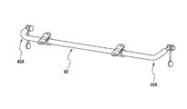
- the hollow stabilizer 40 of the present embodiment is a hollow stabilizer having a Vickers hardness of 400 HV or more and less than 580 HV while cold bending the ERW steel pipe 5 for manufacturing the hollow stabilizer into a shape as shown in FIG. 3. is there.
- a portion denoted by reference numeral 40A is an example of a bent portion.
- the hollow stabilizer includes, for example, a forming step of performing a bending process on the ERW steel tube 5 for manufacturing the hollow stabilizer, and a heat treatment step of performing a heat treatment including a quenching process or a quenching and tempering process after the forming process.
- the hardness after the heat treatment is adjusted to a Vickers hardness of 400 HV or more and less than 580 HV, and the device is manufactured. Further, a shot blasting treatment may be applied to the inner surface, outer surface, or inner and outer surface of the pipe.
- the material is bent into a desired stabilizer shape.
- any known molding method can be applied.
- the treatment in the forming step is preferably performed by cold bending from the viewpoint of suppressing surface decarburization.
- rotary drawing is used as cold bending.
- the steel is selected from the range of a bending radius of 1.0 to 3.0 times the outer diameter of the ERW steel tube 5 before cold bending by cold rotary bending. Bend to a bending radius.
- the flattening rate when bending at this bending radius is set to 0% or more and 10% or less.
- control is performed so that the wall thickness reduction rate outside the bending and the wall thickness expansion rate inside the bending are 0% or more and 10% or less, and the change in the circumferential length of the bending center portion is 0% or more and 10% or less.
- Bending curvature Bending radius R / Steel pipe outer diameter
- Flatness ⁇ (major axis-minor axis) / original diameter ⁇ x
- Increase / decrease wall thickness ⁇ (wall thickness of (bending inside or bending outside)-original thickness) / original thickness ⁇ x
- Perimeter change rate ⁇ (perimeter of bending center part-original perimeter) / original perimeter ⁇ x 100
- the flatness is small in order to suppress stress concentration.
- the oblateness exceeds 10%, the durability life is reduced due to local stress concentration.
- the oblateness is set to 0% or more and 10%. It was confirmed that the flattening rate could be controlled to be 0% or more and 10% or less when bending to a bending radius of 1.0 times or more and 3.0 times or less the outer diameter before processing.
- both the thickness reduction on the outside of the bend and the thickness increase on the inside of the bend are small. If any of them exceeds 10%, local stress concentration occurs due to stress concentration on the thin portion and imbalance of the stress balance of the entire bent portion, resulting in a reduction in durability life. For this reason, both the outside wall thickness reduction rate and the inside wall thickness increase rate are set to 0% or more and 10% or less.
- the change in the circumference of the bent portion is preferably small, and if the circumference is reduced to more than 10%, the stress generated in the bent portion increases, so that the durability life is shortened. For this reason, the change in the circumferential length at the center of the bending is set to 0% or more and 10% or less.
- the steel pipe when the steel pipe is pulled in the axial direction, the steel pipe undergoes two deformations, a deformation in which the diameter is reduced in the circumferential direction and a deformation in which the thickness is reduced in the thickness direction, at a certain ratio.
- the rate of deformation that reduces the diameter in the circumferential direction increases, and the deformation that decreases in the thickness direction tends to decrease. That is, it is difficult to reduce the wall thickness, and the steel pipe expands while reducing its diameter like a candy.
- the steel pipe when manufacturing the stabilizer, the steel pipe is bent. At that time, the outside of the bend is subjected to the same tensile deformation as that of the steel pipe, but the inside of the bend is subjected to the opposite compressive deformation.
- the r value in the tube axis direction is adjusted to be 0.7 or more and less than 1.0.
- the thickness reduction on the outside of the bend and the increase in the thickness on the inside of the bend increase. May be shortened.
- the r value is 1.0 or more, the circumferential length of the pipe becomes short, so that the stress generated in the bent portion increases, and the life may be shortened.
- the heat treatment step includes heat treatment of quenching and tempering.
- the material is heated to a temperature of not less than the Ac 3 transformation point, preferably not more than 1100 ° C., and held for a predetermined time, preferably not less than 1 second, and then put into a quenching tank. It is preferable to perform rapid cooling below. Thereby, the hollow stabilizer of the present embodiment can have high strength and high toughness. If the quenching heating temperature is higher than 1100 ° C., the austenite grains become coarse. In addition, it is preferable that heating is electric heating from the viewpoint of suppression of surface decarburization and productivity.
- the refrigerant in the quenching tank is water, quenching oil, or a mixture of water and a polymer whose concentration has been adjusted.
- the tempering temperature is preferably adjusted according to the desired hardness.
- the tempering temperature is preferably from 200 ° C to 450 ° C.
- the toughness is significantly improved.
- the heat treatment it is needless to say that ordinary shot blasting is preferably applied to the inner surface, the outer surface or the inner and outer surfaces of the pipe in order to improve the fatigue resistance.
- the hardness after the heat treatment is set to a high strength of not less than 400 HV and less than 580 HV in Vickers hardness.
- “high strength” means a case where the average hardness in the thickness direction is Vickers hardness and the lower limit of the hardness HV is 400 HV, preferably the lower limit of the hardness HV is 450 HV. Shall be.
- the average hardness in the thickness direction is 580 HV or more, the toughness is significantly reduced. Therefore, the upper limit is set to less than 580 HV.
- excellent in fatigue characteristics refers to a case in which a fatigue test (load swing) with a load stress of ⁇ 400 MPa is performed and the number of repetitions until crack generation is 200,000 or more. .
- the hollow stabilizer of the present embodiment is a high-strength stabilizer having an HV hardness of 400 or more after tempering, and has a small flatness even if the bending radius of the bending shoulder portion of the stabilizer is small, so that the fatigue property is low. Excellent. Therefore, it is suitable as a stabilizer and can contribute to hollowing (lightening).
- Table 1 shows the composition of the hot-rolled steel sheet used in this example.
- a hot-rolled steel sheet (sheet thickness: 4.3 mm) was continuously formed by a plurality of rolls in a cold state to obtain a substantially cylindrical open pipe. Then, circumferential ends of the open pipe are abutted and pressed against each other, and are subjected to ERW welding using a high-frequency electric resistance welding method to form an ERW steel pipe 2 (outer diameter 89.1 mm ⁇ ⁇ wall thickness 4.3 mm). did. Further, the obtained ERW steel pipe 2 was heated to the heating temperature shown in Table 2, and then subjected to a diameter reduction step of reducing the diameter at a reduction rate shown in Table 2 with a stretch reducer, and the dimensions shown in Table 2 were obtained.
- Table 2 also shows the measured values of the tensile properties of the electric resistance welded steel pipe 5 for manufacturing each hollow stabilizer. Further, each ERW steel pipe 5 for manufacturing each hollow stabilizer was bent into an L-shape by rotary drawing to produce each test piece simulating a hollow stabilizer. At this time, bending conditions and heat treatment conditions of quenching and tempering shown in Table 2 were applied.
- the bending process is a cold rotary bending process in which the bent portion of the L-shaped ERW pipe 5 is bent at a bending radius of 1.5 times the outer diameter.
- the quenching treatment was such that the steel pipe outer surface was heated so as to have a heating temperature shown in Table 2 and then immersed in a water tank.
- a hardness measurement piece was collected from each specimen before shot blasting, and the hardness was measured. The hardness is measured on a section (C section) perpendicular to the pipe axis direction of the steel pipe, and a Vickers hardness meter (load: 500 gf (4.9 N)) at a pitch of 0.1 mm from the outer surface of the pipe to the inner surface of the pipe in the thickness direction. This was performed using Further, in the torsional fatigue test, a fatigue test (load swing) at a load stress: ⁇ 400 MPa at a location where the generated stress is maximum (at a position approximately 60 degrees in the circumferential direction of the pipe from the inside of the bend) was performed. investigated. Note that the test conditions were a load stress of ⁇ 400 MPa (double swing) and a frequency of 1 Hz. Table 2 shows the obtained results.
- tube No. 2 and tube no. Comparison of Nos. 19 to 21 shows that even if the same steel material is used and the hardness after the heat treatment is both 500 HV and high strength, when the Rankford value of the ERW pipe 5 is out of the range of the present invention, the pipe No. As shown in 19 to 21, the number of repetition of the durability until the destruction by the fatigue test is less than 200,000. Thus, it can be seen that by setting the Rankford value of the ERW steel pipe 5 within the range of the present invention, it is possible to obtain a hollow stabilizer excellent in bending workability and fatigue characteristics when the same high strength is obtained.
- tube No. In No. 10 since the strength was 590 HV, the toughness was lowered and the durability was deteriorated. That is, tube No. In No. 10, since the hardness of the final product was forcibly increased to 590 HV, the product suffered from burning cracking and the life was shortened. Tube No. In Nos. 15 and 16, since the content of S was too large as a material or the content of Ca was absent, MnS-based expanded inclusions were generated, and cracks originating from the inclusions were generated. In addition, tube No. In Nos. 11 to 14, the hardness is less than 400 HV, which is not high strength. Therefore, the number of durability repetitions up to the destruction by the fatigue test is less than 200,000. However, by setting the Rankford value of the ERW pipe 5 within the range of the present invention, the fatigue characteristics are improved as compared with the case where the Rankford value of the ERW pipe 5 is out of the range of the present invention.
- the bending workability and fatigue characteristics of the ERW pipe 5 for manufacturing the hollow stabilizer can be improved. Can be done. Furthermore, if a hollow stabilizer having a hardness of 400 HV or more and less than 580 HV is manufactured using the electric resistance welded steel pipe 5 for manufacturing a hollow stabilizer, a high-strength hollow stabilizer excellent in bending workability and fatigue characteristics can be obtained. Do you get it.
Landscapes
- Chemical & Material Sciences (AREA)
- Engineering & Computer Science (AREA)
- Mechanical Engineering (AREA)
- Organic Chemistry (AREA)
- Materials Engineering (AREA)
- Metallurgy (AREA)
- Thermal Sciences (AREA)
- Crystallography & Structural Chemistry (AREA)
- Physics & Mathematics (AREA)
- Manufacturing & Machinery (AREA)
- Heat Treatment Of Articles (AREA)
- Vehicle Body Suspensions (AREA)
- Heat Treatment Of Steel (AREA)
Abstract
Priority Applications (6)
| Application Number | Priority Date | Filing Date | Title |
|---|---|---|---|
| CN201980042850.9A CN112368410B (zh) | 2018-06-27 | 2019-04-24 | 中空稳定器制造用电阻焊钢管、中空稳定器以及它们的制造方法 |
| KR1020207035437A KR102437796B1 (ko) | 2018-06-27 | 2019-04-24 | 중공 스태빌라이저 제조용의 전봉 강관, 중공 스태빌라이저, 및 그것들의 제조 방법 |
| MX2020013761A MX2020013761A (es) | 2018-06-27 | 2019-04-24 | Tubo de acero soldado por resistencia electrica para la produccion de estabilizador hueco, estabilizador hueco, y metodo para la produccion de los mismos. |
| EP19826460.8A EP3816313B1 (fr) | 2018-06-27 | 2019-04-24 | Tuyau en acier soudé par résistance électrique pour produire un stabilisateur creux, stabilisateur creux et son procédé de production |
| JP2019544936A JP6885472B2 (ja) | 2018-06-27 | 2019-04-24 | 中空スタビライザー製造用の電縫鋼管、及びその製造方法 |
| US17/254,394 US12172487B2 (en) | 2018-06-27 | 2019-04-24 | Electric-resistance-welded steel pipe for producing hollow stabilizer, hollow stabilizer, and method for producing same |
Applications Claiming Priority (2)
| Application Number | Priority Date | Filing Date | Title |
|---|---|---|---|
| JP2018121799 | 2018-06-27 | ||
| JP2018-121799 | 2018-06-27 |
Publications (1)
| Publication Number | Publication Date |
|---|---|
| WO2020003720A1 true WO2020003720A1 (fr) | 2020-01-02 |
Family
ID=68987054
Family Applications (1)
| Application Number | Title | Priority Date | Filing Date |
|---|---|---|---|
| PCT/JP2019/017399 Ceased WO2020003720A1 (fr) | 2018-06-27 | 2019-04-24 | Tuyau en acier soudé par résistance électrique pour produire un stabilisateur creux, stabilisateur creux et son procédé de production |
Country Status (7)
| Country | Link |
|---|---|
| US (1) | US12172487B2 (fr) |
| EP (1) | EP3816313B1 (fr) |
| JP (1) | JP6885472B2 (fr) |
| KR (1) | KR102437796B1 (fr) |
| CN (1) | CN112368410B (fr) |
| MX (1) | MX2020013761A (fr) |
| WO (1) | WO2020003720A1 (fr) |
Cited By (2)
| Publication number | Priority date | Publication date | Assignee | Title |
|---|---|---|---|---|
| JP2023036442A (ja) * | 2021-09-02 | 2023-03-14 | Jfeスチール株式会社 | 電縫鋼管およびその製造方法 |
| EP4098380A4 (fr) * | 2020-03-18 | 2023-07-12 | JFE Steel Corporation | Tuyau en acier soudé par résistance électrique et son procédé de production, et élément structural pour automobile |
Families Citing this family (4)
| Publication number | Priority date | Publication date | Assignee | Title |
|---|---|---|---|---|
| DE102021208073A1 (de) | 2021-07-27 | 2023-02-02 | Thyssenkrupp Ag | Rohrstabilisator für ein Fahrzeugfahrwerk und ein Fahrzeugfahrwerk umfassend den Rohrstabilisator |
| PL246193B1 (pl) * | 2023-02-20 | 2024-12-16 | Zalawa Dariusz Dar Stal | Urządzenie do wytwarzania rur spawanych ze szwem wzdłużnym obrobionych cieplnie ze stali wielofazowych |
| PL246192B1 (pl) * | 2023-02-20 | 2024-12-16 | Zalawa Dariusz Dar Stal | Sposób wytwarzania rur spawanych ze szwem wzdłużnym obrobionych cieplnie ze stali wielofazowych |
| CN116586913B (zh) * | 2023-06-13 | 2025-12-09 | 东风商用车有限公司 | 一种前悬横向稳定杆、前悬横向稳定杆总成及制造方法 |
Citations (10)
| Publication number | Priority date | Publication date | Assignee | Title |
|---|---|---|---|---|
| JP2003201543A (ja) * | 2001-10-25 | 2003-07-18 | Jfe Steel Kk | 加工性に優れた鋼管およびその製造方法 |
| JP2005076047A (ja) * | 2003-08-28 | 2005-03-24 | Jfe Steel Kk | 耐疲労特性に優れた中空スタビライザの製造方法 |
| JP2006206999A (ja) * | 2005-01-31 | 2006-08-10 | Jfe Steel Kk | 高強度中空スタビライザ用電縫鋼管および高強度中空スタビライザの製造方法 |
| JP2009191330A (ja) * | 2008-02-15 | 2009-08-27 | Nisshin Steel Co Ltd | 電縫鋼管 |
| JP2010121157A (ja) * | 2008-11-18 | 2010-06-03 | Jfe Steel Corp | 耐腐食疲労特性に優れた高強度中空部材用電縫溶接鋼管 |
| JP2010274716A (ja) * | 2009-05-27 | 2010-12-09 | Nhk Spring Co Ltd | 中空スタビライザ |
| JP2013203309A (ja) * | 2012-03-29 | 2013-10-07 | Nhk Spring Co Ltd | 中空スタビライザ |
| US20170009321A1 (en) * | 2015-07-09 | 2017-01-12 | Benteler Steel/Tube Gmbh | Chassis or drive component |
| WO2017056384A1 (fr) * | 2015-09-29 | 2017-04-06 | Jfeスチール株式会社 | Tube en acier soudé par résistance électrique pour stabilisateur creux à haute résistance et procédé de fabrication d'un tel tube, stabilisateur creux à haute résistance et son procédé de fabrication |
| JP2018121799A (ja) | 2017-01-31 | 2018-08-09 | 株式会社吉田製作所 | X線撮影装置およびx線撮影方法 |
Family Cites Families (9)
| Publication number | Priority date | Publication date | Assignee | Title |
|---|---|---|---|---|
| KR100545621B1 (ko) | 2001-03-07 | 2006-01-24 | 신닛뽄세이테쯔 카부시키카이샤 | 중공 스태빌라이저용 전봉 용접 강관 |
| JP5303842B2 (ja) * | 2007-02-26 | 2013-10-02 | Jfeスチール株式会社 | 偏平性に優れた熱処理用電縫溶接鋼管の製造方法 |
| CN101182749B (zh) | 2007-12-14 | 2012-07-25 | 重庆华厦门窗有限责任公司 | 一种断热桥实腹钢门窗复合型材及其制造方法 |
| JP5142792B2 (ja) * | 2008-04-01 | 2013-02-13 | 日新製鋼株式会社 | 高疲労寿命焼入れ・焼戻し鋼管およびその製造方法 |
| BR112014028915B1 (pt) * | 2012-05-25 | 2019-05-14 | Nippon Steel & Sumitomo Metal Corporation | Estabilizador oco, e tubo de aço para estabilizadores ocos e método de produção dos mesmos |
| JP5867474B2 (ja) | 2013-09-25 | 2016-02-24 | Jfeスチール株式会社 | 電縫溶接部の信頼性に優れた高炭素電縫溶接鋼管の製造方法 |
| JP6784476B2 (ja) | 2015-03-24 | 2020-11-11 | 日本発條株式会社 | 中空スタビライザの製造方法 |
| EP3476953B1 (fr) | 2016-10-24 | 2022-01-05 | JFE Steel Corporation | Tuyau en acier soudé par résistance électrique destiné à un stabilisateur creux mince à haute résistance et son procédé de fabrication |
| JP6796472B2 (ja) * | 2016-12-09 | 2020-12-09 | 日本製鉄株式会社 | 中空部材及びその製造方法 |
-
2019
- 2019-04-24 EP EP19826460.8A patent/EP3816313B1/fr active Active
- 2019-04-24 US US17/254,394 patent/US12172487B2/en active Active
- 2019-04-24 JP JP2019544936A patent/JP6885472B2/ja active Active
- 2019-04-24 KR KR1020207035437A patent/KR102437796B1/ko active Active
- 2019-04-24 WO PCT/JP2019/017399 patent/WO2020003720A1/fr not_active Ceased
- 2019-04-24 MX MX2020013761A patent/MX2020013761A/es unknown
- 2019-04-24 CN CN201980042850.9A patent/CN112368410B/zh active Active
Patent Citations (11)
| Publication number | Priority date | Publication date | Assignee | Title |
|---|---|---|---|---|
| JP2003201543A (ja) * | 2001-10-25 | 2003-07-18 | Jfe Steel Kk | 加工性に優れた鋼管およびその製造方法 |
| JP2005076047A (ja) * | 2003-08-28 | 2005-03-24 | Jfe Steel Kk | 耐疲労特性に優れた中空スタビライザの製造方法 |
| JP2006206999A (ja) * | 2005-01-31 | 2006-08-10 | Jfe Steel Kk | 高強度中空スタビライザ用電縫鋼管および高強度中空スタビライザの製造方法 |
| JP2009191330A (ja) * | 2008-02-15 | 2009-08-27 | Nisshin Steel Co Ltd | 電縫鋼管 |
| JP2010121157A (ja) * | 2008-11-18 | 2010-06-03 | Jfe Steel Corp | 耐腐食疲労特性に優れた高強度中空部材用電縫溶接鋼管 |
| JP5287164B2 (ja) | 2008-11-18 | 2013-09-11 | Jfeスチール株式会社 | 耐腐食疲労特性に優れた高強度中空部材用電縫溶接鋼管 |
| JP2010274716A (ja) * | 2009-05-27 | 2010-12-09 | Nhk Spring Co Ltd | 中空スタビライザ |
| JP2013203309A (ja) * | 2012-03-29 | 2013-10-07 | Nhk Spring Co Ltd | 中空スタビライザ |
| US20170009321A1 (en) * | 2015-07-09 | 2017-01-12 | Benteler Steel/Tube Gmbh | Chassis or drive component |
| WO2017056384A1 (fr) * | 2015-09-29 | 2017-04-06 | Jfeスチール株式会社 | Tube en acier soudé par résistance électrique pour stabilisateur creux à haute résistance et procédé de fabrication d'un tel tube, stabilisateur creux à haute résistance et son procédé de fabrication |
| JP2018121799A (ja) | 2017-01-31 | 2018-08-09 | 株式会社吉田製作所 | X線撮影装置およびx線撮影方法 |
Non-Patent Citations (1)
| Title |
|---|
| See also references of EP3816313A4 |
Cited By (4)
| Publication number | Priority date | Publication date | Assignee | Title |
|---|---|---|---|---|
| EP4098380A4 (fr) * | 2020-03-18 | 2023-07-12 | JFE Steel Corporation | Tuyau en acier soudé par résistance électrique et son procédé de production, et élément structural pour automobile |
| US12173835B2 (en) | 2020-03-18 | 2024-12-24 | Jfe Steel Corporation | Electric resistance welded steel pipe, method for manufacturing the same, and automotive structural member |
| JP2023036442A (ja) * | 2021-09-02 | 2023-03-14 | Jfeスチール株式会社 | 電縫鋼管およびその製造方法 |
| JP7700594B2 (ja) | 2021-09-02 | 2025-07-01 | Jfeスチール株式会社 | 電縫鋼管およびその製造方法 |
Also Published As
| Publication number | Publication date |
|---|---|
| JPWO2020003720A1 (ja) | 2020-07-02 |
| EP3816313A4 (fr) | 2021-05-05 |
| EP3816313A1 (fr) | 2021-05-05 |
| US20210268862A1 (en) | 2021-09-02 |
| MX2020013761A (es) | 2021-03-02 |
| EP3816313B1 (fr) | 2024-11-06 |
| JP6885472B2 (ja) | 2021-06-16 |
| CN112368410A (zh) | 2021-02-12 |
| US12172487B2 (en) | 2024-12-24 |
| CN112368410B (zh) | 2022-05-10 |
| KR102437796B1 (ko) | 2022-08-29 |
| KR20210006977A (ko) | 2021-01-19 |
Similar Documents
| Publication | Publication Date | Title |
|---|---|---|
| JP6332473B2 (ja) | 高強度中空スタビライザー用電縫鋼管、高強度中空スタビライザー用電縫鋼管の製造方法、高強度中空スタビライザー、および高強度中空スタビライザーの製造方法 | |
| JP6885472B2 (ja) | 中空スタビライザー製造用の電縫鋼管、及びその製造方法 | |
| CN104968821B (zh) | 电阻焊钢管 | |
| JP6631758B1 (ja) | 中空スタビライザー製造用の電縫鋼管、中空スタビライザー、及びそれらの製造方法 | |
| CN104395487A (zh) | 空心稳定杆和空心稳定杆用钢管及其制造方法 | |
| WO2018079398A1 (fr) | Tuyau en acier soudé par résistance électrique destiné à un stabilisateur creux mince à haute résistance et son procédé de fabrication | |
| WO2001096624A1 (fr) | Tuyau en acier a haute teneur en carbone, possedant d'excellentes aptitudes au formage a froid et a la trempe a haute frequence, et procede de production associe | |
| WO2010110490A1 (fr) | Tuyau d'acier soudé électriquement par résistance ayant une excellente aptitude au façonnage et d'excellentes caractéristiques de fatigue après trempe | |
| KR102830472B1 (ko) | 전봉 강관, 그 제조 방법 및 자동차용 구조 부재 | |
| JP5211843B2 (ja) | 耐圧潰性に優れた溶接鋼管およびその製造方法 | |
| JP5005543B2 (ja) | 焼入れ性、熱間加工性および疲労強度に優れた高強度厚肉電縫溶接鋼管およびその製造方法 | |
| WO2009119570A1 (fr) | Tube d'acier uoe pour tubes de canalisation et son procédé de fabrication | |
| JP7138779B2 (ja) | 中空スタビライザー用電縫鋼管及び中空スタビライザー、並びにそれらの製造方法 | |
| CN113557317A (zh) | 中空稳定器用电阻焊钢管和其制造方法 | |
| JP5942572B2 (ja) | 耐疲労特性に優れた自動車部品用電縫溶接鋼管およびその製造方法 | |
| JP5512231B2 (ja) | 静的ねじり強度に優れたドライブシャフト用電縫鋼管およびその製造方法 | |
| JP7733348B1 (ja) | 中空鋼部品 | |
| JP6287363B2 (ja) | 疲労特性に優れた中空材とその製造方法 | |
| WO2025187706A1 (fr) | Composant en acier creux | |
| CN119980076A (zh) | 一种防倾杆用高强度冷拔焊管及其制造方法 |
Legal Events
| Date | Code | Title | Description |
|---|---|---|---|
| ENP | Entry into the national phase |
Ref document number: 2019544936 Country of ref document: JP Kind code of ref document: A |
|
| 121 | Ep: the epo has been informed by wipo that ep was designated in this application |
Ref document number: 19826460 Country of ref document: EP Kind code of ref document: A1 |
|
| ENP | Entry into the national phase |
Ref document number: 20207035437 Country of ref document: KR Kind code of ref document: A |
|
| NENP | Non-entry into the national phase |
Ref country code: DE |
|
| ENP | Entry into the national phase |
Ref document number: 2019826460 Country of ref document: EP Effective date: 20210127 |