WO2020003741A1 - Connecteur de ligne - Google Patents
Connecteur de ligne Download PDFInfo
- Publication number
- WO2020003741A1 WO2020003741A1 PCT/JP2019/018259 JP2019018259W WO2020003741A1 WO 2020003741 A1 WO2020003741 A1 WO 2020003741A1 JP 2019018259 W JP2019018259 W JP 2019018259W WO 2020003741 A1 WO2020003741 A1 WO 2020003741A1
- Authority
- WO
- WIPO (PCT)
- Prior art keywords
- exterior member
- circumferential direction
- partition
- line
- exterior
- Prior art date
- Legal status (The legal status is an assumption and is not a legal conclusion. Google has not performed a legal analysis and makes no representation as to the accuracy of the status listed.)
- Ceased
Links
Images


Classifications
-
- B—PERFORMING OPERATIONS; TRANSPORTING
- B25—HAND TOOLS; PORTABLE POWER-DRIVEN TOOLS; MANIPULATORS
- B25J—MANIPULATORS; CHAMBERS PROVIDED WITH MANIPULATION DEVICES
- B25J19/00—Accessories fitted to manipulators, e.g. for monitoring, for viewing; Safety devices combined with or specially adapted for use in connection with manipulators
-
- B—PERFORMING OPERATIONS; TRANSPORTING
- B65—CONVEYING; PACKING; STORING; HANDLING THIN OR FILAMENTARY MATERIAL
- B65H—HANDLING THIN OR FILAMENTARY MATERIAL, e.g. SHEETS, WEBS, CABLES
- B65H75/00—Storing webs, tapes, or filamentary material, e.g. on reels
- B65H75/02—Cores, formers, supports, or holders for coiled, wound, or folded material, e.g. reels, spindles, bobbins, cop tubes, cans, mandrels or chucks
- B65H75/34—Cores, formers, supports, or holders for coiled, wound, or folded material, e.g. reels, spindles, bobbins, cop tubes, cans, mandrels or chucks specially adapted or mounted for storing and repeatedly paying-out and re-storing lengths of material provided for particular purposes, e.g. anchored hoses, power cables
- B65H75/38—Cores, formers, supports, or holders for coiled, wound, or folded material, e.g. reels, spindles, bobbins, cop tubes, cans, mandrels or chucks specially adapted or mounted for storing and repeatedly paying-out and re-storing lengths of material provided for particular purposes, e.g. anchored hoses, power cables involving the use of a core or former internal to, and supporting, a stored package of material
-
- H—ELECTRICITY
- H01—ELECTRIC ELEMENTS
- H01R—ELECTRICALLY-CONDUCTIVE CONNECTIONS; STRUCTURAL ASSOCIATIONS OF A PLURALITY OF MUTUALLY-INSULATED ELECTRICAL CONNECTING ELEMENTS; COUPLING DEVICES; CURRENT COLLECTORS
- H01R35/00—Flexible or turnable line connectors, i.e. the rotation angle being limited
- H01R35/04—Turnable line connectors with limited rotation angle with frictional contact members
-
- H—ELECTRICITY
- H02—GENERATION; CONVERSION OR DISTRIBUTION OF ELECTRIC POWER
- H02G—INSTALLATION OF ELECTRIC CABLES OR LINES, OR OF COMBINED OPTICAL AND ELECTRIC CABLES OR LINES
- H02G11/00—Arrangements of electric cables or lines between relatively-movable parts
- H02G11/02—Arrangements of electric cables or lines between relatively-movable parts using take-up reel or drum
Definitions
- the present invention relates to a line connection connector that enables a connection line (wiring or piping) to be provided across a mounting object such as a link that is connected to be relatively displaceable in, for example, a robot arm.
- a connection line wiring or piping
- connection line for example, in a robot arm, wiring for supplying electric power and transmitting and receiving electric signals, piping for applying air pressure and hydraulic pressure, and the like are provided so as to extend from the base end side to the distal end side across the joint. There is. In this case, any damage to the connection line due to excessive pulling of the connection line such as wiring and piping when driving the joint, obstruction of movement such as bending and extension or torsion of the robot arm, and excessive loosening of the connection line may occur. It is necessary to arrange the connection line so as to prevent the above.
- Patent Document 1 discloses that a striated body (connection line) is folded back into a U-shape at a joint that connects the link so that the link can be relatively displaced. There has been proposed a joint drive device that allows relative rotation of the joint.
- Patent Literature 1 the required relative rotation amount of the link is limited by the length of the striated body even if the striated body is folded back in a U-shape, so that the required rotation is required. It was difficult to apply when the amount was large. In addition, if the length of the filament accommodated in the accommodation space is too long in order to obtain a large permissible rotation of the link, there is a risk that the filament will become entangled and stable operation will not be realized.
- the present invention has been made in view of the above circumstances, and a problem to be solved is to provide a wiring or a pipe (connection line) extending between mounting targets while allowing a large relative displacement of the mounting target.
- a line connection connector having a novel structure.
- the first aspect of the present invention is a line connection connector, wherein the first exterior member and the second exterior member are combined with each other in a mode that allows relative circumferential displacement, and A housing space extending in the circumferential direction is formed between the first exterior member and the second exterior member, and at least one partition member that divides the housing space into a plurality of divided regions each extending in the circumferential direction,
- the first exterior member and the second exterior member are arranged in a manner in which relative displacement in the circumferential direction is allowed, and the first exterior member and one of the second exterior member are arranged with respect to one another.
- a driven mechanism for driving the partition member is a line connection connector, wherein the first exterior member and the second exterior member are combined with each other in a mode that allows relative circumferential displacement, and A housing space extending in the circumferential direction is formed between the first exterior member and the second exterior member, and at least one partition member that divides the housing space into a plurality of divided regions each extending in the circumferential direction,
- the line connection connector having the structure according to the first aspect, when the first exterior member and the second exterior member rotate relative to each other, the partition member that partitions the plurality of divided regions into the first exterior member and the first exterior member. After being driven in the entrained state with respect to one of the exterior member and the second exterior member, by being driven in the entrained state with respect to any other, by the connection lines arranged in the plurality of divided regions, The relative rotation between the first exterior member and the second exterior member can be largely allowed. As a result, while relatively permitting relative rotation about the rotation axis between the mounting target to which the first exterior member is mounted and the mounting target to which the second exterior member is mounted, the mounting object is straddled between the mounting targets. Arrangement of connection lines can be realized.
- connection lines are arranged in the plurality of divided areas partitioned by the partition member, even if the connection lines are lengthened, the connection lines are hardly entangled, and the first exterior member and the second exterior member are stabilized. Relative rotation.
- an exterior member side protrusion is provided on one of the first exterior member and the second exterior member
- the partition member is provided with a partition member side projection, and the partition member is separated from one of the first exterior member and the second exterior member by a relative circumferential displacement of the partition member.
- the driven mechanism is configured such that the member-side projections abut in the circumferential direction.
- the driven mechanism for rotating the partition member with respect to the first exterior member or the second exterior member by mechanical locking of the exterior member side projection and the partition member side projection is improved by a simple structure. With high reliability.
- a third aspect of the present invention is the line connection connector according to the first or second aspect, wherein the plurality of partition members that are mutually displaceable in the circumferential direction are provided in parallel with each other.
- a rotation limiting mechanism for limiting the relative circumferential displacement of the partition member is provided.
- three or more divided regions are formed by a plurality of relatively rotatable partition members, and a longer connection line can be accommodated without being entangled, and a plurality of partition members can be accommodated.
- the relative rotation amount increases when the members rotate relative to each other, the relative rotation of the partition members is limited by the rotation limiting mechanism, and the partition members rotate together. Therefore, the relative rotation of the first exterior member and the second exterior member can be largely tolerated by the longer connection lines arranged in the plurality of divided regions.
- an intermediate projection is provided on each of the plurality of partition members, and the partition member is provided with a relative circumferential displacement by a relative circumferential displacement.
- the rotation restricting mechanism is constituted by the intermediate projections abutting each other in the circumferential direction.
- the rotation limiting mechanism for limiting the relative rotation amount between the partition members by mechanical locking between the intermediate projections provided on the partition member is provided with excellent reliability by a simple structure. Can be realized.
- the first exterior member and the second exterior member have a length exceeding half a circumference in a circumferential direction. And the first exterior member and the second exterior member can be expanded at least in a part of the circumferential direction.
- the first exterior member and the second exterior member when the first exterior member and the second exterior member are externally attached to the mounting target, the first exterior member and the second exterior member having a length exceeding half a circumference are provided.
- the member can be easily attached to and detached from the mounting target.
- the first exterior member and the second exterior member are each formed in an annular shape, and the first exterior member The member and the second exterior member are configured to be dividable into a plurality extending in the circumferential direction, and further, a connection mechanism is provided in which at least one of the first exterior member and the second exterior member interconnects the divided portions. Is what it is.
- both the first exterior member and the second exterior member are formed in an annular shape, the relative rotation of the first exterior member and the second exterior member and the partition member The relative rotation between the first and second exterior members is more smoothly generated.
- first exterior member and the second exterior member can be divided, when the first exterior member and the second exterior member are later mounted in an exterior state with respect to the mounting target, Mounting of the first exterior member and the second exterior member is facilitated.
- connection mechanism in the mounted state, it is possible to prevent the first exterior member and the second exterior member from falling off from the mounting target.
- the first exterior member, the second exterior member, and the partition member each have an arc shape. It is said that.
- the line connection connector when the line connection connector is retrofitted to the mounting target in an exterior state, the line connection connector is formed in an arc shape, so that the line connection connector can be easily mounted on the mounting target. be able to.
- the positioning for positioning the connection lines accommodated in the plurality of divided areas with respect to the partition member. Means are provided.
- a portion of the connection line that is positioned with respect to the partition member is the second exterior member.
- connection line between the plurality of divided areas since the movement of the connection line between the plurality of divided areas is prevented, for example, it is possible to prevent the length of the connection line from becoming too long in a specific divided area, thereby facilitating entanglement.
- connection line extending between the first exterior member and the second exterior member that are relatively rotatable, and a partition member that partitions the accommodation space into a plurality of divided areas.
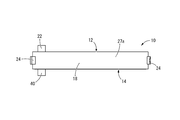
- FIG. 1 is a perspective view showing a line connector according to a first embodiment of the present invention.
- the front view of the line connection connector shown in FIG. The top view of the line connection connector shown in FIG.
- FIG. 3 is a right side view of the line connection connector shown in FIG. 2.
- FIG. 2 is an exploded perspective view of the line connection connector shown in FIG. 1.
- 3A and 3B are diagrams illustrating the operation of the line connection connector illustrated in FIG. 2, wherein FIG. 3A illustrates an initial state in which the connector is not rotated, FIG. The rotated state is shown.
- FIG. 6 is a perspective view showing a line connection connector as a second embodiment of the present invention.
- FIG. 10 is a front view of the line connection connector shown in FIG. 9.
- the top view of the line connection connector shown in FIG. The right side view of the line connection connector shown in FIG. XIII-XIII sectional drawing of FIG.
- FIG. 10 is an exploded perspective view of the line connection connector shown in FIG. 9.
- 11A and 11B are diagrams for explaining the operation by the upper half of the line connector shown in FIG. 10, wherein FIG. 10A shows an initial state in which the line connection is not rotated, FIG. The state rotated by more than ° is shown.
- FIG. 9 is a perspective view showing a line connection connector as a third embodiment of the present invention.
- FIG. 17 is a cross-sectional view of the line connection connector shown in FIG.
- FIG. 16 which corresponds to a cross section taken along line XVII-XVII of FIG. 16
- FIG. 18 is a cross-sectional view of the line connection connector shown in FIG. 16, which corresponds to a cross section taken along line XVIII-XVIII in FIG. 17
- FIG. 14 is a sectional view showing a line connector according to a fourth embodiment of the present invention. The perspective view showing the line connection connector as another embodiment of the present invention.
- FIGS. 1 to 6 show a line connection connector 10 as a first embodiment of the present invention.
- the line connection connector 10 has a structure in which a partition member 16 is disposed between a first exterior member 12 and a second exterior member 14.
- the up-down direction refers to the up-down direction in FIG. 2
- the axial direction refers to the direction orthogonal to the plane of FIG.
- the first exterior member 12 is formed of a hard synthetic resin, metal, or the like, is formed in an annular shape as a whole, and is directed toward one axial direction (left side in FIG. 5) as shown in FIGS. And has a groove-shaped cross-section extending in the circumferential direction. Further, as shown in FIG. 7, the first exterior member 12 includes a first upper half body 18 and a first lower half body 20, each of which extends for approximately half the circumference in the circumferential direction. It is configured such that both ends in the direction are abutted against each other, and has a vertically divided structure. Furthermore, a first terminal portion 22 is provided at one end in the circumferential direction of the first lower half body 20 so that a connection line 70 described later is connected.
- connection claw portion 24 that protrudes outward in the circumferential direction is provided at one end in the circumferential direction of the first upper half body 18, and one end of the first lower half body 20 in the circumferential direction is provided.
- connection protrusion 26 at one end, and one end in the circumferential direction of the first upper half body 18 and the first lower half body 20 butted against each other is connected to the connection claw 24.
- the connection projections 26 are connected to each other by locking.
- the other circumferential ends of the first upper half body 18 and the first lower half body 20 butted against each other are connected to connecting projections 26 provided on the first upper half body 18.
- both ends in the circumferential direction of the first upper half body 18 and the first lower half body 20 are connected by a connecting mechanism constituted by locking of the connecting claws 24, 24 and the connecting projections 26, 26. They are interconnected in a separable manner.
- the first exterior member 12 can be expanded by separation at two locations where the first upper half body 18 and the first lower half body 20 abut against each other in the circumferential direction.
- annular first outer peripheral groove portion 28 and a second outer peripheral groove portion 30 which are open to the inner peripheral surface and extend in the circumferential direction are continuously formed on the outer peripheral side wall portion 27a of the first exterior member 12 over the entire periphery. It is formed.
- the first outer peripheral groove 28 is formed at the opening of the first exterior member 12, while the second outer peripheral groove 30 is formed at the bottom wall of the first exterior member 12 more than the first outer peripheral groove 28. It is formed at a position near 27b.
- the first outer peripheral groove 28 and the second outer peripheral groove 30 have substantially the same groove cross-sectional shape.
- first outer peripheral groove 28 and the second outer peripheral groove 30 each have an inner wall with an inclined surface 35 at both ends in the circumferential direction of the first upper half body 18 and the first lower half body 20.
- the groove width dimension gradually increases outward in the circumferential direction of the first upper half body 18 and the first lower half body 20.
- annular first inner peripheral groove portion 32 and a second inner peripheral groove portion 34 which are open to the outer peripheral surface and extend in the circumferential direction are provided on the entire periphery. It is formed continuously throughout.
- the first inner peripheral groove 32 is formed in an opening portion of the first exterior member 12, while the second inner peripheral groove 34 is formed on the first exterior member 12 more than the first inner peripheral groove 32. It is formed at a position close to the bottom wall 27b.
- the first inner peripheral groove 32 and the second inner peripheral groove 34 have substantially the same groove cross-sectional shape.
- the first inner peripheral groove portion 32 and the second inner peripheral groove portion 34 each have an inclined inner wall surface at both circumferential ends of the first upper half body 18 and the first lower half body 20.
- the groove width is gradually increased outward in the circumferential direction of the first upper half body 18 and the first lower half body 20.
- the first outer peripheral groove 28 and the first inner peripheral groove 32 are arranged at substantially the same axial position and oppose each other in the radial direction, and the second outer peripheral groove 30 and the second inner peripheral groove 34 Are arranged at substantially the same axial position and oppose each other in the radial direction.
- the second exterior member 14 is formed of a hard synthetic resin, metal, or the like, and has a substantially annular plate shape as a whole. Further, in the second exterior member 14, a second upper half-divided body 36 and a second lower half-divided body 38, each of which extends in the circumferential direction with a length of substantially half a circumference, abut the circumferential ends. And a divided structure vertically divided. Further, a second terminal portion 40 is provided at one end in the circumferential direction of the second lower half body 38 so that a connection line 70 described later is connected.
- an exterior member side projection 42 is provided at one end in the circumferential direction of the second lower half body 38. As shown in FIGS. 6 and 7, the exterior member side projection 42 is a projection that projects from the second exterior member 14 to a later-described housing space 48.
- the second lower half body At one end in the circumferential direction of 38, it is formed integrally with the outer peripheral end.
- the second exterior member 14 is provided with an outer peripheral projection 44 projecting toward the outer periphery and an inner peripheral projection 46 projecting toward the inner periphery.
- the outer peripheral protrusion 44 and the inner peripheral protrusion 46 are both thinner than the radially intermediate portion of the second exterior member 14, and are provided substantially continuously over the entire circumference in the circumferential direction. .
- the second exterior member 14 is disposed so as to close the opening of the first exterior member 12, and is attached to the first exterior member 12 so as to be relatively displaceable (relatively rotated) in the circumferential direction. ing.
- the outer peripheral projection 44 of the second exterior member 14 is inserted into the first outer peripheral groove 28 of the first exterior member 12, and the inner peripheral projection 46 of the second exterior member 14 is It is inserted into the first inner peripheral groove 32 of the first exterior member 12.
- the outer peripheral projection 44 and the inner peripheral projection 46 are guided in the circumferential direction by the first outer peripheral groove 28 and the first inner peripheral groove 32, and the first exterior member 12 and the second ,
- the relative circumferential displacement of the exterior member 14, that is, relative rotation is allowed.
- the second exterior member 14 becomes the first exterior member 12. Is limited in the axial direction with respect to the first outer member 12 and the second outer member 14 are prevented from being separated in the axial direction.
- first exterior member 12 and the second exterior member 14 are configured such that the second upper half body 36 is inserted into the first upper half body 18 from below and the second lower half body 38 Are inserted into the first lower half body 20 from above, and the first upper half body 18 and the first lower half body 20 are connected by the connecting mechanism (the connecting claws 24, 24 and the connecting protrusion 26). , 26) to form an interconnected state.
- the first exterior member 12 and the second exterior member 14 are configured such that an upper half body 18, 36 and a lower half body 20, 38 are separable, and the upper half body 18, 36 and the lower half body 18, 36 are separated from each other.
- the first exterior member 12 and the second exterior member 14 can be expanded (divided) between the circumferential ends of the half bodies 20 and 38.
- the line connection connector 10 can be connected to the robot arm 72 described later. It is easy to put on and take off.
- annular housing space 48 extending in the circumferential direction is formed between the first exterior member 12 and the second exterior member 14.
- both the first terminal portion 22 of the first exterior member 12 and the second terminal portion 40 of the second exterior member 14 are exposed to the accommodation space 48, and the second exterior member 14
- the exterior member side projection 42 projects into the housing space 48.
- the partition member 16 is disposed in the housing space 48.
- the partition member 16 has a substantially annular plate shape similar to the second exterior member 14 as a whole, and in the present embodiment, as shown in FIG.
- the upper partition member 50 and the lower partition member 52 have a divided structure configured to be combined so that their circumferential ends abut against each other. Note that the partition member 16 does not need to have the completely same shape as the second exterior member 14.
- a conductive terminal portion 54 is provided at one end of the lower partition member 52 in the circumferential direction.
- the conductive terminal portions 54 are exposed on both surfaces of the lower partition member 52, and are connected to a first line 66 and a second line 68 described later.
- a partition member-side projection 56 is formed integrally with the other end of the lower partition member 52 in the circumferential direction.
- the partition member side projection 56 projects toward the second exterior member 14 in the thickness direction of the partition member 16, and in the present embodiment, the outer peripheral end of the lower partition member 52 at the other end in the circumferential direction. Are formed integrally.
- the partition member 16 is integrally formed with an outer peripheral protrusion 58 protruding on the outer peripheral surface and an inner peripheral protrusion 60 protruding on the inner peripheral surface.
- the outer peripheral protrusion 58 and the inner peripheral protrusion 60 are both thinner than the radially intermediate portion of the partition member 16 and are provided substantially continuously over the entire circumference in the circumferential direction.
- the partition member 16 is inserted into the axially intermediate portion of the first exterior member 12 and is disposed between the bottom wall 27b of the first exterior member 12 and the second exterior member 14 in the axial direction. ing. That is, the outer peripheral projection 58 of the partition member 16 is inserted into the second outer peripheral groove 30 of the first exterior member 12, and the inner peripheral projection 60 of the partition member 16 is inserted into the second inner groove 30 of the first exterior member 12.
- the partition member 16 is assembled to the first exterior member 12 by being inserted into the peripheral groove portion 34.
- the partition member 16 is configured such that the outer peripheral protrusion 58 and the inner peripheral protrusion 60 are guided by the second outer peripheral groove 30 and the second inner peripheral groove 34, and Thus, it is assembled in a manner that allows relative circumferential displacement.
- the outer peripheral projection 58 and the inner peripheral projection 60 abut against the inner surfaces of the groove widths of the second outer peripheral groove 30 and the second inner peripheral groove 34, so that the partition member 16 can be moved in the axial direction with respect to the first exterior member 12.
- the amount of displacement is limited.
- the accommodation space 48 is divided into two on both sides in the axial direction of the partition member 16, and the first divided region 62 and the second divided region 64 are formed on both sides of the partition member 16. .
- the accommodation space 48 is constituted by the first divided region 62 and the second divided region 64 formed on both axial sides of the partition member 16.
- the partition member 16 is disposed substantially at the center of the accommodation space 48 in the axial direction, and the first divided region 62 and the second divided region 64 are spaces having substantially the same shape and size.
- the first divided region 62 and the second divided region 64 may have different shapes and sizes from each other.
- the first divided region 62 and the second divided region 64 accommodate a first line 66 and a second line 68, respectively.
- the first and second lines 66 and 68 of the present embodiment are formed in a thin strip shape such as a flexible printed circuit (FPC) in which a predetermined printed wiring is formed from a conductive material such as copper on a resin film as a flexible insulating substrate. And have substantially the same structure as each other, and extend in the circumferential direction by a length of about half a circumference in a front view.
- FPC flexible printed circuit
- the portions accommodated in the first and second divided regions 62 and 64 are folded at the curved folded portion 71, and both sides of the folded portion 71 are pivoted. Since they are arranged to face each other in the direction, they have a substantially semicircular arc shape in a front view and a length of substantially one circumference.
- the first line 66 is disposed in the first divided region 62, and one end of the first line 66 is connected to the first terminal 22 of the first exterior member 12. The other end of the first line 66 is connected to the conductive terminal 54 of the partition member 16 (see FIG. 6). Further, a second line 68 is provided in the second divided region 64, and one end of the second line 68 is connected to the second terminal 40 of the second exterior member 14. The other end of the second line 68 is connected to the conductive terminal 54 of the partition member 16. As a result, the first line 66 and the second line 68 are electrically connected to each other via the conductive terminal portion 54 to form the connection line 70 as a whole, and both ends of the connection line 70 are connected to the first line. The terminal portion 22 and the second terminal portion 40 electrically connect to the outside in the axial direction.
- first and second lines 66 are connected to the first terminal portion 22 or the second terminal portion 40 and the conduction terminal portion 54 as described above, the first and second lines 66 are formed. , 68, both ends are positioned with respect to each of the first exterior member 12 and the second exterior member 14, and an intermediate portion is positioned with respect to the partition member 16.
- the conductive terminal portion 54 constitutes the positioning means of the present embodiment. Since the first line 66 and the second line 68 each have a length of about one round, the connection line 70 has a length of about two rounds as a whole.
- the first exterior member 12 is attached to the first link 74 of the robot arm 72
- the second exterior member 14 is attached to the robot arm 72. It is attached to the second link 76 of the robot arm 72 and is attached later to the robot arm 72.
- the first link 74 and the second link 76 to be mounted are connected to each other via a joint 78, and a relative torsional displacement (a relative rotation in a circumferential direction) is allowed.
- the external wiring (not shown) on the first link 74 side is connected to the first terminal portion 22 of the line connection connector 10, and the external wiring (not shown) on the second link 76 side is connected to the line connection connector 10. By being connected to the second terminal section 40, these external wirings are electrically connected by the connection line 70.
- connection line 70 is housed in the lower half of the housing space 48.
- the exterior member side projection 42 provided on the second exterior member 14 (the second lower half body 38) and the partition member side projection 56 provided on the partition member 16 are substantially mutually reciprocal in the circumferential direction. They are arranged at a distance of half a circumference.
- the illustration of the second upper half body 36 of the second exterior member 14 is omitted for easy understanding.
- the second exterior member 14 moves relative to the first exterior member 12 until the exterior member side projection 42 comes into contact with the partition member side projection 56.
- the folded portion 71 of the second line 68 moves in the accommodation space 48 in the circumferential direction.
- the second exterior member 14 rotates relative to the first exterior member 12 from the initial state of FIG. 8A to the position of FIG. And the second exterior member 14 relatively rotates with respect to the partition member 16 so that the relative position of the exterior member-side projection 42 and the partition member-side projection 56 in the circumferential direction is changed.
- the inertial force acting on the partition member 16, the outer peripheral protrusion 58 and the inner peripheral protrusion 60 of the partition member 16, the second outer peripheral groove 30 of the first exterior member 12, and the second inner peripheral A driven mechanism that causes the partition member 16 to follow the first exterior member 12 in a stopped state is formed by frictional resistance acting between the groove member 34 and the like.
- the driven mechanism that makes the second exterior member 14 and the partition member 16 follow the first exterior member 14 and the partition member 16 is allowed to rotate relative to the second exterior member 14 by a predetermined amount, and then the second exterior member 14 and the partition member 16 are separated from each other.
- the member 16 is caused to rotate.
- the second exterior member 14 and the partition member 16 do not follow from the initial stage of the relative rotation of the first exterior member 12 and the second exterior member 14,
- a driven mechanism is formed, and during the relative rotation between the first exterior member 12 and the second exterior member 14, the partition member 16 14.
- the driven mechanism of the present embodiment includes a first driven mechanism that drives the first exterior member 12 and the partition member 16 in a stopped state, and a second driven member 14 and the partition member 16 that are driven to rotate.
- the driven second driven mechanism selectively functions according to the relative rotation amount of the first exterior member 12 and the second exterior member 14.
- the partition member 16 follows the first exterior member 12 in a rotating state. That is, in the above-described embodiment, assuming that the second exterior member 14 is stopped and the first exterior member 12 is rotating, the partition member 16 is configured to rotate the first exterior member 12 from the initial rotation of the first exterior member 12. The partition member 16 is driven by the exterior member 12 in a co-rotating state, and thereafter, the relative rotation of the partition member 16 with respect to the second exterior member 14 is limited, so that the partition member 16 is in contact with the first exterior member 12. The entrainment is stopped, and instead, it follows the second exterior member 14, stops rotating together with the second exterior member 14, and only the first exterior member 12 relatively rotates.
- the partition member 16 When the partition member 16 is driven by the driven mechanism with respect to the second exterior member 14, the partition member 16 rotates relative to the first exterior member 12 together with the second exterior member 14, and the Since the conductive terminal portion 54 of the member 16 is displaced in the circumferential direction with respect to the first terminal portion 22 of the first exterior member 12, both ends of the first line 66 disposed in the first divided region 62 Changes in the circumferential direction.
- the relative rotation of the first exterior member 12 and the second exterior member 14 is not only the deformation of the second line 68 due to the relative rotation of the partition member 16 and the second exterior member 14, but also the relative rotation of the partition member 16 Due to the deformation of the first line 66 due to the relative rotation of the first exterior member 12, greater tolerance is allowed.
- the relative rotation between the first exterior member 12 and the second exterior member 14 is controlled by the first stage in which the second line 68 is deformed and the second stage in which the first line 66 is deformed.
- Using the entirety of 70 is largely acceptable. Therefore, according to the line connector 10, even for the robot arm 72 that performs a larger torsion operation, the wiring (connection line 70) extending between the first link 74 and the second link 76 inhibits the torsion operation. It can be provided without.
- connection line 70 is arranged in the first divided region 62 and the second divided region 64 partitioned by the partition member 16, so that the connection line The connection line 70 can be prevented from becoming entangled in the housing space 48 while the length of the entire 70 is set to be sufficiently long, so that operation stability and reliability are improved.
- the partition member-side projection 56 of the partition member 16 is pressed in the circumferential direction by the exterior member-side projection 42 of the second exterior member 14.
- the force is directly transmitted between the second exterior member 14 and the partition member 16. Therefore, it is difficult for tensile stress to act on the connection line 70 and disconnection of the connection line 70 is avoided, so that excellent durability and reliability can be realized.
- both the first line 66 and the second line 68 are positioned with respect to the partition member 16, the relative rotation of the partition member 16, the first exterior member 12, and the second exterior member 14 is determined. Can be tolerated by the deformation without requiring a change in the length of the first line 66 and the second line 68.
- first line 66 does not enter the second divided region 64
- second line 68 does not enter the first divided region 62.
- the length of 66 and the length of the second line 68 accommodated in the second divided area 64 are kept constant.
- both ends of the first line 66 are positioned on each of the first exterior member 12 and the partition member 16, and both ends of the second line 68 are located on the second exterior member 14. Since the first line 66 and the second line 68 are positioned on each one of the partition members 16, a change in the length of the first line 66 and the second line 68 is avoided.
- the first exterior member 12 and the second exterior member 14 are formed in an annular shape, and the first exterior member 12 and the second exterior member 14 are It has a divided structure composed of the half bodies 18 and 36 and the lower half bodies 20 and 38. Therefore, by combining the upper half body 18, 36 and the lower half body 20, 38 vertically around the outer periphery of the first link 74 and the second link 76, the first exterior member 12 and the second exterior The member 14 can be easily attached to the first link 74 and the second link 76 in an exterior state.
- the partitioning member 16 has a divided structure including the upper partitioning member 50 and the lower partitioning member 52, and the connection line 70 is disposed on the lower half of the housing space 48.
- the entirety of the connector 10 has a divided structure that can be vertically divided into two parts, and the exterior of the first and second links 74 and 76 is easy.
- the first and second outer peripheral groove portions 28 and 30 and the first and second outer half groove portions 30 are formed. Since the inner circumferential grooves 32 and 34 have tapered side walls (inclined surfaces 35) whose axial dimension gradually increases outward in the circumferential direction, the second exterior member 14, the partition member 16, Is smoothly guided in the circumferential direction without being caught at the abutting portion of the first upper half body 18 and the first lower half body 20.
- first upper half body 18 and the first lower half body 20 are provided with a connecting mechanism including a connecting claw 24 and a connecting protrusion 26 at both ends in the circumferential direction.
- the line connecting connector 10 can be easily attached to the robot arm 72 by connecting the upper half body 18 and the first lower half body 20 with the connecting mechanism in a state of being covered with the first link 74. In addition, the line connector 10 is unlikely to fall off the robot arm 72.
- FIG. 8 shows a state in which the initial state (FIG. 8A) is rotated by more than 180 ° (FIG. 8C), the first exterior member 12 and the second exterior member 14 are shown. Is allowed to rotate relatively up to approximately 540 ° depending on the length of the first line 66 and the second line 68. Further, since both the first line 66 and the second line 68 are folded back in the circumferential direction, rotation in the direction opposite to the rotation direction shown in FIG. 8 is also permitted, and approximately ⁇ 540 ° The relative rotation between the first exterior member 12 and the second exterior member 14 is allowed within the range of.
- the relative rotation amount allowed between the first exterior member 12 and the second exterior member 14 is, for example, the length of the first line 66 and the second line 68 and the exterior member side projection in the initial state.
- the distance is appropriately set according to the circumferential distance between the portion 42 and the partition member-side protrusion 56.
- the maximum relative rotation amount of the first exterior member 12 and the second exterior member 14 is defined by the length of the first line 66.
- Rotation amount defining means may be provided between the partition members 16. This rotation amount defining means is, for example, similar to a driven mechanism, in which a projection provided on the first exterior member 12 and a projection provided on the partition member 16 are locked in the circumferential direction.
- the first line 66 is formed by limiting the amount of relative rotation of the partition member 16 with the first exterior member 12 that is configured to rotate with the second exterior member 14 by the driven mechanism by contact of the projections.
- the maximum relative rotation amount between the first exterior member 12 and the second exterior member 14 can be defined while preventing the effect of tensile stress on the first exterior member 12.
- the exterior member-side projection 42 and the partition member-side projection 56 are arranged at positions substantially half a circumference in the circumferential direction.
- the relative rotation between the member 12 and the second exterior member 14 is allowed on both sides in the circumferential direction.
- the initial circumferential positions of the exterior member-side projection 42 and the partition member-side projection 56 are particularly Not limited.
- the exterior member side projection 42 is provided on the second upper half body 36, and the exterior member side projection 42 is located at a position closer to the counterclockwise direction than the partition member side projection 56. If provided, the relative rotation amount allowed between the first exterior member 12 and the second exterior member 14 can be set to be larger in the counterclockwise direction than in the clockwise direction.
- FIGS. 9 to 12 show a line connection connector 80 according to a second embodiment of the present invention.
- the line connection connector 80 has a structure in which a partition member 86 is disposed between a first exterior member 82 and a second exterior member 84.
- a partition member 86 is disposed between a first exterior member 82 and a second exterior member 84.
- the first exterior member 82 is formed of a hard synthetic resin, metal, or the like, and extends in the circumferential direction with a groove-shaped cross section that opens toward the inner periphery as shown in FIG. It is shaped. Further, as shown in FIG. 14, the first exterior member 82 includes a first upper half body 88 and a first lower half body 90, each of which extends in the circumferential direction with a length of substantially half a circumference. It is configured such that both ends in the direction are abutted against each other, and has a vertically divided structure. Further, a line insertion hole 92 corresponding to the outer shape of a first line 114 described later is formed at one end in the circumferential direction of the first upper half body 88.
- connection claw 24 and the connection protrusion 26 is provided at each of both circumferential ends of the first upper half body 88, and both circumferential ends of the first lower half body 90 are provided.
- the connection protruding portion 26 and the connection claw portion 24 are provided on the portion, and both circumferential ends of the first upper half body 88 and the first lower half body 90 butted against each other, respectively.
- the connection is formed in a separable manner by a connection mechanism configured by locking the connection claw 24 and the connection protrusion 26.
- a first groove portion 94 is formed in the side wall portion on both sides in the axial direction of the first exterior member 82 so as to open to the inner surface in the axial direction at the inner peripheral end and extend continuously over the entire circumference in the circumferential direction. Have been.
- an exterior member side projection 106 is provided at the other end in the circumferential direction of the first upper half body 88. As shown in FIG. 13, the exterior member-side projection 106 projects from the first exterior member 82 to an accommodation space 48 described below.
- the first upper half body having a groove shape is used. At the other end in the circumferential direction of 88, it is integrally formed inside the side wall portion. In other words, at the other end in the circumferential direction of the first upper half body 88, the side wall part in the axial direction is thickened inward, so that the exterior member side protrusion 106 of the present embodiment is formed. Have been.
- the second exterior member 84 is formed of a hard synthetic resin, metal, or the like, extends in the circumferential direction with a groove-shaped cross section opened toward the outer periphery, and has a substantially annular shape as a whole. Further, on the side wall portion of the second exterior member 84, an outer peripheral projection 96 that projects outward in the axial direction from the outer peripheral end is formed integrally and continuously over substantially the entire circumference. Furthermore, a second groove 98 that opens inward in the axial direction at the outer peripheral end of the side wall portion of the second exterior member 84 extends continuously over substantially the entire circumference in the circumferential direction.
- the second exterior member 84 includes a second upper half body 100 and a second lower half body 102, each of which extends in the circumferential direction by a length of substantially half a circumference. It is configured to be combined so that both ends in the circumferential direction abut, and has a divided structure vertically divided. Further, at one end in the circumferential direction of the second upper half body 100, a line insertion hole 104 corresponding to the outer shape of a second line 116 described later is formed.
- the second exterior member 84 is disposed on the inner periphery so as to close the opening of the first exterior member 82, and is assembled so as to be relatively rotatable with respect to the first exterior member 82.
- the outer peripheral projection 96 of the second exterior member 84 is inserted into the first groove 94 of the first exterior member 82, and the outer peripheral projection 96 is By being guided in the circumferential direction by the groove portion 94, relative circumferential displacement (relative rotation) of the first exterior member 82 and the second exterior member 84 is allowed.
- first exterior member 82 and the second exterior member 84 are configured such that the second upper half body 100 is inserted into the first upper half body 88 in the circumferential direction and the second lower half body In a state where the body 102 is inserted into the first lower half body 90 in the circumferential direction, the first upper half body 88 and the first lower half body 90 are connected to each other by the connecting mechanism (the connecting claws 24, 24). Are connected to each other by the connecting protrusions 26, 26), thereby being formed in a mutually combined state.
- the connecting mechanism the connecting claws 24, 24
- annular housing space 48 extending in the circumferential direction is formed between the first exterior member 82 and the second exterior member 84. Have been.
- a partition member 86 is provided in the housing space 48. As shown in FIG. 14, the partition member 86 has a substantially annular or cylindrical shape as a whole, and each of the partition member 86 has a band-shaped upper partition member 108 and a band-shaped lower partition member 110 extending in a circumferential direction by a length of substantially half a circumference. Have a divided structure configured to be combined so that both ends in the circumferential direction abut against each other.
- a conductive terminal portion 111 is provided at one end of the upper partition member 108 in the circumferential direction. As shown in FIG. 13, the conductive terminal portion 111 is exposed on both surfaces of the upper partition member 108, and is connected to one end of each of a first line 114 and a second line 116 described later.
- a partition member side projection 112 is integrally formed at one end in the circumferential direction of the upper partition member 108.
- the partition member-side projection 112 projects toward the first exterior member 82 in the thickness direction of the partition member 86, and is integrally formed at the axial end in the present embodiment.
- the partition member 86 is inserted into the outer peripheral end of the second exterior member 84 and is disposed radially between the first exterior member 82 and the second exterior member 84. That is, by inserting both ends in the axial direction of the partition member 86 into the second groove 98 of the second exterior member 84, the partition member 86 is positioned and assembled in the radial direction with respect to the second exterior member 84. ing. Further, the partition member 86 is allowed to be displaced in the circumferential direction relative to the second exterior member 84 by guiding both ends in the axial direction by the second grooves 98.
- the accommodation space 48 is divided into two on both sides in the radial direction of the partition member 86, and the first divided region 62 and the second divided region 64 are formed on both sides of the partition member 86. ing.
- the first divided region 62 and the second divided region 64 accommodate a first line 114 and a second line 116, respectively.
- the first and second lines 114 and 116 of the present embodiment are insulated electric wires having a substantially circular cross section in which the periphery of a linear conductor is covered with an insulator, have substantially the same structure as each other, and are viewed from the front. It extends in the circumferential direction with a length of about half a circumference. Further, in the first and second lines 114 and 116, portions accommodated in the first and second divided regions 62 and 64 are folded back at the curved folded portion 71, and the first and second lines 114 and 116 are the same as those of the first embodiment. Like the first and second lines 66 and 68, each of the first and second lines 66 has a substantially semicircular arc shape when viewed from the front, and has a length of substantially one round.
- the first line 114 is provided in the first divided region 62, and one end of the first line 114 is taken out to the outside through the line insertion hole 92 of the first exterior member 82. The other end of the first line 114 is connected to the conductive terminal 111 of the partition member 86.
- the second line 116 is provided in the second divided region 64, and one end of the second line 116 is taken out to the outside through the line insertion hole 104 of the second exterior member 84. The other end of the second line 116 is connected to the conductive terminal 111 of the partition member 86.
- the first line 114 and the second line 116 are electrically connected to each other via the conductive terminal portion 111 to form the connection line 118 as a whole, and both ends of the connection line 118 are inserted through the line.
- the holes are taken out on both sides in the axial direction through the holes 92 and 104.
- the first line 114 and the second line 116 are inserted into the line insertion holes 92 and 104 and are connected to the conductive terminal portion 111, so that the first and second lines 114 are , 116, both end portions are positioned with respect to one of the first exterior member 82 and the second exterior member 84, and an intermediate portion is positioned with respect to the partition member 86.
- the conductive terminal 111 constitutes the positioning means of the present embodiment.
- the line connection connector 80 having such a structure is, for example, a first exterior member 82 is attached to a first link as an attachment object (not shown), and a second exterior member 84 is attached to an attachment object (not shown).
- the first link and the second link are attached to the second link, and are retrofitted to a robot arm having a structure in which the first link and the second link are rotatably connected.
- An external wiring (not shown) on the first link side is connected to one end (not shown) of the connection line 118 extending outward in the axial direction through the line insertion hole 92 of the first exterior member 82.
- connection line 118 an external wiring (not shown) on the second link side is connected to the other end (not shown) of the connection line 118 extending outward in the axial direction through the line insertion hole 104 of the second exterior member 84.
- these external wirings are mutually connected by the connection line 118.
- connection line 118 is housed in the upper half of the housing space 48.
- the exterior member side projection 106 provided on the first exterior member 82 (first upper half body 88 in FIG. 15) and the partition provided on the partition member 86 (upper partition member 108 in FIG. 15).
- the member-side protrusions 112 are arranged at a distance of substantially half a circumference from each other in the circumferential direction.
- the first exterior member 82, the second exterior member 84, and the partition member 86 the first lower half body 90 and the second lower half body 102
- the illustration of the lower partition member 110 is omitted.
- the first exterior member 82 is connected to the second exterior member 84 (within a range in which the exterior member side projection 106 and the partition member side projection 112 are not locked in the circumferential direction.
- the second exterior member 84 in the case of relative rotation with respect to the second upper half body 100 in FIG. 15, when the insertion portion of the first line 114 is moved with respect to the line insertion hole 92, the folded portion of the first line 114 is moved.
- the relative rotation (relative circumferential displacement) of the first exterior member 82 and the second exterior member 84 is allowed by the 71 moving in the first divided region 62 in the circumferential direction.
- the partition member 86 does not substantially rotate relative to the second exterior member 84 because the external force in the circumferential direction hardly acts, and the first exterior member 82 rotates relative to the partition member 86. Then, the exterior member side projection 106 and the partition member side projection 112 approach in the circumferential direction. Then, in the state shown in FIG. 15B, the exterior member side projection 106 and the partition member side projection 112 come into contact with each other in the circumferential direction.
- the inertial force acting on the partition member 86 and the force acting between the axial both ends of the partition member 86 and the second groove 98 of the second exterior member 84 are provided.
- a driven mechanism that causes the partition member 86 to follow the second exterior member 84 in a stopped state by the frictional resistance or the like is configured.
- the partition member 86 is driven (rotated) with respect to the first exterior member 82, and the partition member 86 is integrally rotated with the first exterior member 82. Displace in the direction.
- the driven mechanism that causes the partition member 86 to follow the first exterior member 82 that is displaced in the circumferential direction in a rotating state includes the exterior member side projection 106 and the partition member side projection 112. Are formed in the circumferential direction.
- the partition member 86 is also relatively rotated with respect to the second exterior member 84, and the conduction terminal portion 111 of the partition member 86 is displaced in the circumferential direction with respect to the line insertion hole 104 of the second exterior member 84. From this, the position of the folded portion 71 of the second line 116 arranged in the second divided area 64 changes in the circumferential direction. As a result, a large relative rotation between the first exterior member 82 and the second exterior member 84 is allowed by the deformation of the second line 116 due to the relative rotation between the partition member 86 and the second exterior member 84, The allowable rotation amount can be changed as appropriate.
- the line connection connector 80 is, like the line connection connector 10 of the first embodiment, the first exterior member 82 and the second exterior member 82 depending on the lengths of both the first line 114 and the second line 116.
- the relative rotation of the second exterior member 84 is allowed to a larger angle. Therefore, the wiring that straddles the first link and the second link that is relatively rotated relatively is realized by the line connection connector 80 without disturbing the relative rotation of the first link and the second link. be able to.
- the first exterior member 82 and the second exterior member 84 are allowed to rotate relatively up to approximately ⁇ 540 °.
- the relative rotation of the partition member 86 with respect to the second exterior member 84 is configured such that the partition member side projection 112 of the partition member 86 is pressed in the circumferential direction by the exterior member side projection 106 of the first exterior member 82.
- FIGS. 16 and 17 show a line connection connector 120 as a third embodiment of the present invention.
- the line connection connector 120 has a structure in which a partition member 126 is disposed between a first exterior member 122 and a second exterior member 124.
- the first exterior member 122 is formed in an annular shape as a whole, has a groove-shaped cross section that opens in one axial direction (the left side in FIG. 17) and extends in the circumferential direction, and has an outer peripheral side wall.
- An outer peripheral protruding portion 128 protruding toward the outer periphery is integrally formed at the opening end of the portion 27a.
- the first exterior member 122 is configured such that the first upper half body 130 and the first lower half body 132, each of which extends in the circumferential direction with a length of substantially half a circumference, abut both circumferential ends. It is configured in combination and has a vertically divided structure.
- the first terminal portion 22 is provided at one end in the circumferential direction of the first upper half body 130.
- the first exterior member 122 includes an annular outer peripheral groove 134 opening on the inner peripheral surface of the outer peripheral side wall 27a, and an annular inner peripheral groove 136 opening on the outer peripheral surface of the inner peripheral side wall 27c.
- the outer peripheral groove portion 134 and the inner peripheral groove portion 136 are provided at substantially the same position in the axial direction, and are opened to face each other in the radial direction.
- the second exterior member 124 has an annular shape as a whole, has a groove-shaped cross section that opens in the other axial direction (the right side in FIG. 17) and extends in the circumferential direction, and has an outer peripheral side wall. At the opening-side end of the portion 27a, a groove-shaped connection portion 138 that opens toward the inner periphery is provided over substantially the entire periphery. Further, the second exterior member 124 is configured such that the second upper half body 140 and the second lower half body 142, each of which extends in the circumferential direction with a length of substantially half a circumference, abut both ends in the circumferential direction. It is configured in combination and has a vertically divided structure. In the present embodiment, the second terminal portion 40 is provided at one circumferential end of the second upper half body 140.
- the elastically protruding outward in the circumferential direction is provided at one end in the circumferential direction of the second upper half body 140 and at the other end in the circumferential direction of the second lower half body 142.
- the support piece 144 is integrally formed, and a locking claw 146 projecting to the inner circumference is integrally formed at the protruding tip portion of the elastic support piece 144.
- a locking claw 146 provided at one end in the circumferential direction of the second upper half body 140 is provided on one end of the second lower half body 142 in the circumferential direction based on the elasticity of the elastic support piece 144.
- a locking claw 146 provided at the other end in the circumferential direction of the second lower half body 142 is provided on the other end of the second upper half body 140 in the circumferential direction based on the elasticity of the elastic support piece 144. Is inserted into a locking groove 148 opened on the outer peripheral surface of the end portion of the base member and locked in the circumferential direction.
- the second upper half body 140 and the second lower half body 142 are connected to each other at both ends in the circumferential direction to form the second exterior member 124.
- an exterior member side projection 150 is integrally formed at the other end in the circumferential direction of the second upper half body 140.
- the exterior member side projection 150 is provided on the inner peripheral surface of the outer peripheral side wall 27a of the second upper half body 140, and the second upper half body 140 is formed at the portion where the exterior member side projection 150 is formed.
- the outer peripheral side wall 27a is partially thick.
- the first exterior member 122 and the second exterior member 124 have inner and outer peripheral side walls that abut against each other in the axial direction, and the outer periphery projection 128 of the first exterior member 122 is the second exterior member.
- the first exterior member 122 and the second exterior member 124 are axially combined with each other by being inserted into the connection portion 138 of the second member 124 in a manner that allows relative displacement in the circumferential direction.
- a housing space 48 extending in the circumferential direction is continuously formed over the entire circumference between the first exterior member 122 and the second exterior member 124 in the axial direction.
- a partition member 126 is provided in the housing space 48.
- the partition member 126 has a substantially annular plate shape. The outer peripheral end is inserted into the outer peripheral groove 134 of the first exterior member 122, and the inner peripheral end is the inner peripheral groove 136 of the first exterior member 122. Is attached to the first exterior member 122 so as to be relatively rotatable. Further, the partitioning member 126 has a divided structure in which an upper partitioning member 152 and a lower partitioning member 154 each extending in the circumferential direction by a length of approximately half a circumference are combined so as to abut the circumferential ends with each other. Have.
- a partition member side protrusion that protrudes toward the second exterior member 124 in the thickness direction (axial direction) at the outer peripheral end is provided at one circumferential end of the upper partition member 152.
- the exterior member side projection 150 of the second exterior member 124 and the partition member side projection 56 of the partition member 126 are formed.
- a driven mechanism that drives the second exterior member 124 and the partition member 126 is configured, and the partition member 126 is integrally held with the second exterior member 124. It turns around.
- a driven mechanism that causes the partition member 126 to follow the first exterior member 122 is also provided.
- the partition member 126 is driven by the first exterior member 122 and the partition member 126 is driven by the second exterior member. Due to the following movement with respect to 124, it is possible to obtain a large relative rotation amount between first exterior member 122 and second exterior member 124.
- FIG. 19 shows a line connection connector 160 as a fourth embodiment of the present invention.
- the line connection connector 160 has a structure in which a first partition member 162 and a second partition member 164 are arranged in parallel in the axial direction between the first exterior member 12 and the second exterior member 14. ing.
- first and second partition members 162 and 164 have a substantially annular plate shape similar to the partition member 16 of the first embodiment, and include the first exterior member 12 and the second Are arranged in a housing space 48 formed between the exterior members 14 and are arranged in parallel at a predetermined distance from each other in the thickness direction.
- first and second partition members 162 and 164 are inserted into the outer peripheral groove portions 30 and 30 that open on the inner peripheral surface of the outer peripheral side wall portion 27 a of the first exterior member 12, and have the inner peripheral end portions. The part is inserted into the inner peripheral grooves 34, 34 that open on the outer peripheral surface of the inner peripheral side wall part 27 c of the first outer member 12, so that the first outer member 12 is relatively rotatable with respect to the first outer member 12.
- first and second partition members 162 and 164 are arranged between the first exterior member 12 and the second exterior member 14, the accommodation space 48 is made up of the first exterior member 12.
- a first divided region 166 between the bottom wall portion 27b and the first partition member 162, a second divided region 168 between the second exterior member 14 and the second partition member 164, and a first partition It is partitioned into a third divided area 170 between the member 162 and the second partition member 164.
- First to third lines (not shown) are provided in the first to third divided areas 166, 168, and 170, and these three lines are provided in the first and second partition members 162 and 164. Conducted in series with each other by a not-shown conducting terminal portion, and constitutes a connection line, and both ends of the connection line are exposed to a first terminal portion and a second terminal portion (not shown) that are exposed to the outside. It is connected.
- first partition member 162 is provided with the first intermediate projection 172
- second partition member 164 is provided with the second intermediate projection 174.
- the first intermediate projection 172 protrudes toward the second partition member 164 in the thickness direction at the outer peripheral end of the first partition member 162.
- the second intermediate projections 174 protrude toward the first partition member 162 in the thickness direction at the outer peripheral end of the second partition member 164, and the intermediate projections 172 and 174 are at least protruded tip portions. Are located on the same circumference.
- an exterior member-side projection (not shown) of the second exterior member 14 and a not-shown partition of the second partition member 164.
- the second partition member 164 which is configured to be locked in the circumferential direction with the member-side protrusion, acts on the second exterior member 14, and acts between the first exterior member 12 and the second partition member 164.
- the relative rotation between the first exterior member 12 and the second exterior member 14 is largely allowed by the driven mechanism of the second partition member 164 constituted by friction resistance or the like with respect to the first exterior member 12.
- the second partition member 164 is driven by the second exterior member 14 in a rotating manner and relatively rotates with respect to the first partition member 162 by a predetermined amount, whereby the first partition member 162 is rotated.
- the first intermediate projection 172 of the second partition member 164 abuts on the first intermediate projection 172 and is locked in the circumferential direction.
- the first partition member 162 is driven by the second partition member 164 in a rotating manner, and the first exterior member 12 is formed by all of the first to third lines constituting the connection line.
- the relative rotation of the second exterior member 14 is larger.
- the relative circumferential displacement (relative rotation) of the plurality of partition members 162, 164 is determined by the circumferential engagement of the first intermediate projection 172 and the second intermediate projection 174.
- a rotation limiting mechanism for limiting is configured. Until the first intermediate projection 172 and the second intermediate projection 174 abut on each other in the circumferential direction, the first partition member 162 is caused to follow the first exterior member 12 based on frictional resistance or the like.
- the accommodation space 48 is divided into three, and the first to third lines constituting the connection line are arranged in the three divided regions 166, 168, 170, so that the first exterior member is provided.
- the relative rotation amount between the second outer member 12 and the second exterior member 14 can be allowed to be larger, and even if a long connection line is adopted, the connection line is hardly entangled and stable operation can be realized.
- first and second partition members 162 are locked by the circumferential engagement between the first intermediate projection 172 of the first partition member 162 and the second intermediate projection 174 of the second partition member 164. , 164 are prevented from acting on the third line disposed between the first and second partition members 162, 164, and the connection line is disconnected. Etc. can be prevented.
- connection line is an electric wiring such as an FPC or an insulated wire, but may be a pipe (tube) for transmitting air pressure or oil pressure.
- connection line 70 may not necessarily have the folded portion 71, and may extend in one circumferential direction without being folded, for example.
- a thin wiring such as a flexible flat cable (FFC) having a thickness direction in the radial direction is wound around one direction in the circumferential direction, so that the first exterior member and the second exterior member are arranged.
- the relative rotation of the exterior member can be allowed by winding and loosening of the wiring.
- FFC flexible flat cable
- the number of the partition members 16 can be three or more. In this case, four or more divided regions are formed, and connection lines are arranged in these divided regions. It is also possible to obtain a large relative rotation amount between the exterior member 12 and the second exterior member 14.
- the partition member 16 does not have to partition the entire storage space 48, and for example, the annular storage space 48 may be partially partitioned in the circumferential direction by the partition member 16. Furthermore, the partition member 16 restricts the movement of the connection line 70 between the plurality of divided regions 62 and 64, and is not necessarily limited to a plate shape, and has, for example, a net-like or lattice-like hole. It may be something.
- the conductive terminal portion 54 provided on the partition member 16 in the above embodiment is not essential, and for example, when the entire connection line 70 is not integrally constituted by a plurality of independent lines but is continuously connected integrally.
- the insertion hole of the connection line 70 is formed in the partition member 16, and the intermediate portion of the connection line 70 is fixed to the partition member 16 in a state where the intermediate portion of the connection line 70 is inserted into the insertion hole.
- Positioning means can also be configured by positioning with respect to the partition member 16.
- the driven mechanism is not limited to the one configured by the locking of the exterior member side projection 42 and the partition member side projection 56 in the circumferential direction.
- the driven mechanism may be constituted by positioning means for positioning the connection line 70 with respect to the partition member 16.
- the circumferential positions of the projections 42 and 56 are Is not particularly limited.
- the exterior member side projection 42 and the partition member side projection 56 are formed by the first exterior member 12 and the second exterior member 14 making substantially one round, so that the projections 42 and 56 It can also be arranged to be mutually locked in direction to form a driven mechanism.
- the driven member is driven by the partition member 16 with respect to one of the first exterior member 12 and the second exterior member 14 so that the partition member 16 and the first exterior member 12 or the second exterior member 14 are not necessarily integrated.
- This does not only mean that the partition member 16 is slightly stopped or displaced, and that the partition member 16 causes some displacement with respect to the stopped exterior member due to input of vibration or the like, or the partition member 16 is rotated at a lower rotation speed than the exterior member. Includes cases in which the person rotates.
- the line connector according to the present invention is not necessarily limited to a ring-shaped structure.
- a semi-annular structure such as a line connector 180 shown in FIG. 20 may be employed.
- the line connection connector can be a robot arm or the like. When retrofitted to a mounting target, it can be easily mounted.
- Each of the first exterior member 82, the second exterior member 84, and the partition member may be formed in an arc (a superior arc) shape that exceeds a half circumference.
- the line connection connector 180 in FIG. 20 has a structure corresponding to the upper half of the line connection connector 80 according to the second embodiment, and includes a connection claw 24 and a connection protrusion 26 which constitute a connection mechanism. Since the structure is omitted, the first exterior member is given the same reference numeral as the first upper half of the second embodiment, and the second exterior member is the second half of the second embodiment. The same reference numerals as those in the upper half are given.
- first link and the second link to be mounted may extend in a direction orthogonal to the rotation axis of the first link and the second link.
- the second link and the second link may behave like bending and stretching at the joint.
- the line connection connector can be easily attached to the mounting target.
- the annular first exterior member 12 and the second exterior member 14 are formed by the upper half-members 18 and 36 and the lower half-members 20 and 38 that extend in the circumferential direction with a length of approximately half the circumference.
- a connecting mechanism that connects the plurality of divided portions to each other in the circumferential direction can be configured at both circumferential ends of each of the divided portions.
- first exterior member 12 and the second exterior member 14 are, for example, a combination of an upper half divided body extending in a circumferential direction with a length exceeding a half circumference and a lower half divided body extending in a circumferential direction with a length less than a half circumference. It can also be configured.
- the superior arc-shaped upper half body can be mounted on the outer peripheral surface of the first link 74 by making the inner diameter of the first exterior member 12 larger than the outer diameter of the first link 74.
- the upper half body can be fitted to the outer peripheral surface of the first link 74 while deforming the upper half body so as to widen the interval between both ends in the circumferential direction.
- the subarc-shaped portion may be further divided into a plurality.
- the mounting target of the line connection connector is not limited to the first and second links 74 and 76 constituting the robot arm 72.
- a joint that allows the waist of the humanoid robot to twist.
- a cable or the like is wired so as to straddle the waist joint, the first exterior member 12 and the second exterior member 14 are located above and below the waist joint of the torso of the humanoid robot. Since it is attached to each one of the sides, the mounting target is a first link forming the upper side of the torso of the humanoid robot and a second link forming the lower side of the torso.
- the mounting object of the line connection connector may be, for example, a rotary drive facility other than a robot in a factory, such as a turntable or a handle.
- the line connection connector according to the present invention can be mounted on a steering column constituting a steering device of an automobile and used.
- the line connection connector is not necessarily limited to the one that is retrofitted to the mounting target, and may be built into the mounting target.
- the first exterior member and the second exterior member may constitute at least a part of each mounting target, such as the first exterior member constituting the exterior of the first link.
Landscapes
- Engineering & Computer Science (AREA)
- Robotics (AREA)
- Mechanical Engineering (AREA)
- Details Of Connecting Devices For Male And Female Coupling (AREA)
- Manipulator (AREA)
Abstract
L'invention concerne un connecteur de ligne présentant une nouvelle structure selon laquelle des fils/tuyaux (lignes de connexion), passant entre des objets à attacher ensemble, peuvent être installés tout en permettant un déplacement relatif important entre les objets à attacher ensemble. Dans la présente invention : un premier élément extérieur (12) et un second élément extérieur (14) sont reliés l'un à l'autre de manière à être relativement mobiles dans une direction circonférentielle l'un par rapport à l'autre; un espace de logement (48) s'étendant dans la direction circonférentielle est formé entre le premier élément extérieur (12) et le second élément extérieur (14); au moins un élément de séparation (16), qui divise l'espace de logement (48) en de multiples régions divisées (62, 64) s'étendant dans la direction circonférentielle, est disposé de façon à être relativement déplaçable dans la direction circonférentielle par rapport au premier élément extérieur (12) et au second élément extérieur (14); et un mécanisme suiveur pour amener l'élément de séparation (16) à se déplacer simultanément au mouvement du premier élément extérieur (12) et/ou du second élément extérieur (14).
Applications Claiming Priority (2)
| Application Number | Priority Date | Filing Date | Title |
|---|---|---|---|
| JP2018122435A JP2020004593A (ja) | 2018-06-27 | 2018-06-27 | ライン接続コネクタ |
| JP2018-122435 | 2018-06-27 |
Publications (1)
| Publication Number | Publication Date |
|---|---|
| WO2020003741A1 true WO2020003741A1 (fr) | 2020-01-02 |
Family
ID=68985556
Family Applications (1)
| Application Number | Title | Priority Date | Filing Date |
|---|---|---|---|
| PCT/JP2019/018259 Ceased WO2020003741A1 (fr) | 2018-06-27 | 2019-05-07 | Connecteur de ligne |
Country Status (2)
| Country | Link |
|---|---|
| JP (1) | JP2020004593A (fr) |
| WO (1) | WO2020003741A1 (fr) |
Citations (5)
| Publication number | Priority date | Publication date | Assignee | Title |
|---|---|---|---|---|
| JPH0752140Y2 (ja) * | 1990-06-14 | 1995-11-29 | アルプス電気株式会社 | ケーブルリール |
| JPH07335355A (ja) * | 1994-06-13 | 1995-12-22 | Furukawa Electric Co Ltd:The | 仮止め機構付回転コネクタ |
| JPH09293575A (ja) * | 1996-04-26 | 1997-11-11 | Alps Electric Co Ltd | 回転コネクタ |
| JP2011078227A (ja) * | 2009-09-30 | 2011-04-14 | Nitta Corp | 電力中継回転継手 |
| JP2013543085A (ja) * | 2010-08-26 | 2013-11-28 | ロタイト・リミテッド | 2つの物品を相互に接続するための装置及び相互に接続する方法 |
-
2018
- 2018-06-27 JP JP2018122435A patent/JP2020004593A/ja active Pending
-
2019
- 2019-05-07 WO PCT/JP2019/018259 patent/WO2020003741A1/fr not_active Ceased
Patent Citations (5)
| Publication number | Priority date | Publication date | Assignee | Title |
|---|---|---|---|---|
| JPH0752140Y2 (ja) * | 1990-06-14 | 1995-11-29 | アルプス電気株式会社 | ケーブルリール |
| JPH07335355A (ja) * | 1994-06-13 | 1995-12-22 | Furukawa Electric Co Ltd:The | 仮止め機構付回転コネクタ |
| JPH09293575A (ja) * | 1996-04-26 | 1997-11-11 | Alps Electric Co Ltd | 回転コネクタ |
| JP2011078227A (ja) * | 2009-09-30 | 2011-04-14 | Nitta Corp | 電力中継回転継手 |
| JP2013543085A (ja) * | 2010-08-26 | 2013-11-28 | ロタイト・リミテッド | 2つの物品を相互に接続するための装置及び相互に接続する方法 |
Also Published As
| Publication number | Publication date |
|---|---|
| JP2020004593A (ja) | 2020-01-09 |
Similar Documents
| Publication | Publication Date | Title |
|---|---|---|
| EP3010684B1 (fr) | Joint tournant d'un robot et robot comprenant celui-ci | |
| CN108136599B (zh) | 机器人关节以及包括机器人关节的机器人 | |
| US7385136B2 (en) | Harness wire cover and harness wiring structure having the same | |
| CN100533871C (zh) | 旋转连接器 | |
| JP2023178254A (ja) | ロボットアームの関節、コネクタ固定具及びロボットアーム | |
| US10611038B2 (en) | Cable-management system, a rotary joint and a robot | |
| US20090176393A1 (en) | Rotary connector | |
| US10647009B2 (en) | Routing unit, a rotary joint and a robot | |
| JP6458116B1 (ja) | 後付コネクタ | |
| WO2020003741A1 (fr) | Connecteur de ligne | |
| US12337469B2 (en) | Flexible structure | |
| US5304071A (en) | Clock spring | |
| JP2018195568A (ja) | 後付コネクタ | |
| JP7583793B2 (ja) | 1本以上のラインのためのロータリガイド | |
| JP2011078227A (ja) | 電力中継回転継手 | |
| JP7115837B2 (ja) | ワイヤハーネス | |
| US10320175B2 (en) | Mechanical link | |
| JP7135815B2 (ja) | ロボット、及びロボットの製造方法 | |
| JP7231481B2 (ja) | ワイヤーハーネス保持具 | |
| JP5549466B2 (ja) | グロメット | |
| JP7377784B2 (ja) | 連結構造 | |
| WO2018211929A1 (fr) | Connecteur adapté | |
| JP7009686B2 (ja) | ジョイント具 | |
| JP2021157924A (ja) | ホルダ及びホルダ組 | |
| WO2025052893A1 (fr) | Composant de fixation de faisceau |
Legal Events
| Date | Code | Title | Description |
|---|---|---|---|
| 121 | Ep: the epo has been informed by wipo that ep was designated in this application |
Ref document number: 19825750 Country of ref document: EP Kind code of ref document: A1 |
|
| NENP | Non-entry into the national phase |
Ref country code: DE |
|
| 122 | Ep: pct application non-entry in european phase |
Ref document number: 19825750 Country of ref document: EP Kind code of ref document: A1 |