WO2020003744A1 - Appareil de photographie par rayonnement, procédé de photographie par rayonnement, et programme - Google Patents
Appareil de photographie par rayonnement, procédé de photographie par rayonnement, et programme Download PDFInfo
- Publication number
- WO2020003744A1 WO2020003744A1 PCT/JP2019/018337 JP2019018337W WO2020003744A1 WO 2020003744 A1 WO2020003744 A1 WO 2020003744A1 JP 2019018337 W JP2019018337 W JP 2019018337W WO 2020003744 A1 WO2020003744 A1 WO 2020003744A1
- Authority
- WO
- WIPO (PCT)
- Prior art keywords
- radiation
- image
- energy
- substances
- energies
- Prior art date
- Legal status (The legal status is an assumption and is not a legal conclusion. Google has not performed a legal analysis and makes no representation as to the accuracy of the status listed.)
- Ceased
Links
Images


Classifications
-
- A—HUMAN NECESSITIES
- A61—MEDICAL OR VETERINARY SCIENCE; HYGIENE
- A61B—DIAGNOSIS; SURGERY; IDENTIFICATION
- A61B6/00—Apparatus or devices for radiation diagnosis; Apparatus or devices for radiation diagnosis combined with radiation therapy equipment
- A61B6/42—Arrangements for detecting radiation specially adapted for radiation diagnosis
- A61B6/4208—Arrangements for detecting radiation specially adapted for radiation diagnosis characterised by using a particular type of detector
- A61B6/4241—Arrangements for detecting radiation specially adapted for radiation diagnosis characterised by using a particular type of detector using energy resolving detectors, e.g. photon counting
-
- A—HUMAN NECESSITIES
- A61—MEDICAL OR VETERINARY SCIENCE; HYGIENE
- A61B—DIAGNOSIS; SURGERY; IDENTIFICATION
- A61B6/00—Apparatus or devices for radiation diagnosis; Apparatus or devices for radiation diagnosis combined with radiation therapy equipment
- A61B6/46—Arrangements for interfacing with the operator or the patient
- A61B6/461—Displaying means of special interest
-
- A—HUMAN NECESSITIES
- A61—MEDICAL OR VETERINARY SCIENCE; HYGIENE
- A61B—DIAGNOSIS; SURGERY; IDENTIFICATION
- A61B6/00—Apparatus or devices for radiation diagnosis; Apparatus or devices for radiation diagnosis combined with radiation therapy equipment
- A61B6/48—Diagnostic techniques
- A61B6/482—Diagnostic techniques involving multiple energy imaging
-
- A—HUMAN NECESSITIES
- A61—MEDICAL OR VETERINARY SCIENCE; HYGIENE
- A61B—DIAGNOSIS; SURGERY; IDENTIFICATION
- A61B6/00—Apparatus or devices for radiation diagnosis; Apparatus or devices for radiation diagnosis combined with radiation therapy equipment
- A61B6/52—Devices using data or image processing specially adapted for radiation diagnosis
- A61B6/5211—Devices using data or image processing specially adapted for radiation diagnosis involving processing of medical diagnostic data
- A61B6/5217—Devices using data or image processing specially adapted for radiation diagnosis involving processing of medical diagnostic data extracting a diagnostic or physiological parameter from medical diagnostic data
-
- A—HUMAN NECESSITIES
- A61—MEDICAL OR VETERINARY SCIENCE; HYGIENE
- A61B—DIAGNOSIS; SURGERY; IDENTIFICATION
- A61B6/00—Apparatus or devices for radiation diagnosis; Apparatus or devices for radiation diagnosis combined with radiation therapy equipment
- A61B6/54—Control of apparatus or devices for radiation diagnosis
-
- A—HUMAN NECESSITIES
- A61—MEDICAL OR VETERINARY SCIENCE; HYGIENE
- A61B—DIAGNOSIS; SURGERY; IDENTIFICATION
- A61B6/00—Apparatus or devices for radiation diagnosis; Apparatus or devices for radiation diagnosis combined with radiation therapy equipment
- A61B6/58—Testing, adjusting or calibrating thereof
- A61B6/582—Calibration
- A61B6/583—Calibration using calibration phantoms
-
- A—HUMAN NECESSITIES
- A61—MEDICAL OR VETERINARY SCIENCE; HYGIENE
- A61B—DIAGNOSIS; SURGERY; IDENTIFICATION
- A61B6/00—Apparatus or devices for radiation diagnosis; Apparatus or devices for radiation diagnosis combined with radiation therapy equipment
- A61B6/58—Testing, adjusting or calibrating thereof
- A61B6/582—Calibration
- A61B6/585—Calibration of detector units
-
- G—PHYSICS
- G01—MEASURING; TESTING
- G01T—MEASUREMENT OF NUCLEAR OR X-RADIATION
- G01T1/00—Measuring X-radiation, gamma radiation, corpuscular radiation, or cosmic radiation
- G01T1/16—Measuring radiation intensity
- G01T1/161—Applications in the field of nuclear medicine, e.g. in vivo counting
-
- G—PHYSICS
- G01—MEASURING; TESTING
- G01T—MEASUREMENT OF NUCLEAR OR X-RADIATION
- G01T1/00—Measuring X-radiation, gamma radiation, corpuscular radiation, or cosmic radiation
- G01T1/16—Measuring radiation intensity
- G01T1/17—Circuit arrangements not adapted to a particular type of detector
-
- G—PHYSICS
- G06—COMPUTING OR CALCULATING; COUNTING
- G06F—ELECTRIC DIGITAL DATA PROCESSING
- G06F18/00—Pattern recognition
- G06F18/20—Analysing
- G06F18/22—Matching criteria, e.g. proximity measures
-
- G—PHYSICS
- G06—COMPUTING OR CALCULATING; COUNTING
- G06T—IMAGE DATA PROCESSING OR GENERATION, IN GENERAL
- G06T11/00—Two-dimensional [2D] image generation
-
- G—PHYSICS
- G06—COMPUTING OR CALCULATING; COUNTING
- G06T—IMAGE DATA PROCESSING OR GENERATION, IN GENERAL
- G06T12/00—Tomographic reconstruction from projections
- G06T12/20—Inverse problem, i.e. transformations from projection space into object space
-
- G—PHYSICS
- G06—COMPUTING OR CALCULATING; COUNTING
- G06T—IMAGE DATA PROCESSING OR GENERATION, IN GENERAL
- G06T7/00—Image analysis
- G06T7/0002—Inspection of images, e.g. flaw detection
- G06T7/0012—Biomedical image inspection
-
- G—PHYSICS
- G06—COMPUTING OR CALCULATING; COUNTING
- G06V—IMAGE OR VIDEO RECOGNITION OR UNDERSTANDING
- G06V10/00—Arrangements for image or video recognition or understanding
- G06V10/98—Detection or correction of errors, e.g. by rescanning the pattern or by human intervention; Evaluation of the quality of the acquired patterns
- G06V10/993—Evaluation of the quality of the acquired pattern
-
- A—HUMAN NECESSITIES
- A61—MEDICAL OR VETERINARY SCIENCE; HYGIENE
- A61B—DIAGNOSIS; SURGERY; IDENTIFICATION
- A61B6/00—Apparatus or devices for radiation diagnosis; Apparatus or devices for radiation diagnosis combined with radiation therapy equipment
- A61B6/52—Devices using data or image processing specially adapted for radiation diagnosis
- A61B6/5258—Devices using data or image processing specially adapted for radiation diagnosis involving detection or reduction of artifacts or noise
-
- G—PHYSICS
- G06—COMPUTING OR CALCULATING; COUNTING
- G06T—IMAGE DATA PROCESSING OR GENERATION, IN GENERAL
- G06T2207/00—Indexing scheme for image analysis or image enhancement
- G06T2207/10—Image acquisition modality
- G06T2207/10116—X-ray image
-
- G—PHYSICS
- G06—COMPUTING OR CALCULATING; COUNTING
- G06T—IMAGE DATA PROCESSING OR GENERATION, IN GENERAL
- G06T2207/00—Indexing scheme for image analysis or image enhancement
- G06T2207/30—Subject of image; Context of image processing
- G06T2207/30004—Biomedical image processing
-
- G—PHYSICS
- G06—COMPUTING OR CALCULATING; COUNTING
- G06T—IMAGE DATA PROCESSING OR GENERATION, IN GENERAL
- G06T2211/00—Image generation
- G06T2211/40—Computed tomography
- G06T2211/408—Dual energy
-
- G—PHYSICS
- G06—COMPUTING OR CALCULATING; COUNTING
- G06V—IMAGE OR VIDEO RECOGNITION OR UNDERSTANDING
- G06V2201/00—Indexing scheme relating to image or video recognition or understanding
- G06V2201/03—Recognition of patterns in medical or anatomical images
-
- G—PHYSICS
- G06—COMPUTING OR CALCULATING; COUNTING
- G06V—IMAGE OR VIDEO RECOGNITION OR UNDERSTANDING
- G06V2201/00—Indexing scheme relating to image or video recognition or understanding
- G06V2201/03—Recognition of patterns in medical or anatomical images
- G06V2201/031—Recognition of patterns in medical or anatomical images of internal organs
Definitions
- the present invention relates to a radiation imaging apparatus, a radiation imaging method, and a program.
- a radiation imaging apparatus using a flat panel detector (hereinafter, abbreviated as "FPD") has become widespread. Since the FPD can perform digital image processing on a captured image, for example, in medical image diagnosis, the FPD is used as a digital imaging device or a CT device for still image imaging such as general imaging or moving image imaging such as fluoroscopic imaging. I have.
- Patent Document 1 a substance is identified by applying a technique called dual energy scan in which an object is photographed using two types of tube voltages in a CT apparatus, and a radiation image is formed using appropriate radiation energy for each substance.
- a generating configuration is disclosed.
- the present invention provides a radiographic technique capable of reconstructing a radiation image by setting different radiation energies for a plurality of substances.
- a radiation imaging apparatus has the following configuration. That is, the radiation imaging apparatus is a generation unit that generates a material characteristic image for a plurality of substances included in a radiation image captured with different radiation energies, Reconstruction means to set different radiation energy for each of the plurality of substances, to generate a reconstructed image based on a monochromatic radiation image for each substance based on the different radiation energy, It is characterized by having.
- a radiation imaging apparatus has the following configuration. That is, the radiation imaging apparatus obtains low-energy radiation distribution information and high-energy high-energy radiation distribution information from a plurality of radiation images obtained by a single radiation irradiation from the radiation generation unit.
- a generation unit that generates a material characteristic image separated into a first substance and a second substance from the low energy radiation distribution information and the high energy radiation distribution information, Generating a reconstructed image based on a monochromatic radiation image based on a first radiation energy corresponding to the first substance and a monochromatic radiation image based on a second radiation energy corresponding to the second substance;
- structural means is provided to obtains low-energy radiation distribution information and high-energy high-energy radiation distribution information from a plurality of radiation images obtained by a single radiation irradiation from the radiation generation unit.
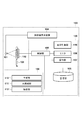
- FIG. 1 is a diagram illustrating a configuration example of a radiation imaging system according to a first embodiment.
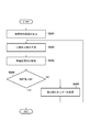
- FIG. 4 is a diagram for explaining the flow of processing in an image processing unit according to the first embodiment.
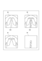
- 3a illustrates a high energy radiation image
- 3b illustrates a low energy radiation image
- 3c illustrates a substance separation image of fat
- 3d illustrates a substance separation image of bone.
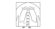
- FIG. 4 is a diagram for explaining the effect of the first embodiment. The figure which illustrates the region of interest for which the analysis value of the first embodiment is obtained.
- FIG. 4 is a diagram for explaining the effect of the first embodiment. The figure which illustrates the region of interest for which the analysis value of the first embodiment is obtained.
- FIG. 1 is a diagram illustrating a configuration example of a radiation imaging system 100 according to the first embodiment of the present invention.
- the radiation imaging system 100 includes a radiation generating device 104, a radiation source 101, an FPD 102 (radiation detecting device), and an information processing device 120. Note that the configuration of the radiation imaging system 100 is also simply referred to as a radiation imaging apparatus.
- the information processing device 120 processes information based on a radiographic image of a subject.
- the radiation generator 104 applies a high-voltage pulse to the radiation source 101 by pressing an irradiation switch to generate radiation, and the radiation source 101 irradiates the subject 103 with radiation.
- the type of radiation is not particularly limited, but generally, X-rays can be used.
- the FPD 102 When radiation is applied to the subject 103 from the radiation source 101, the FPD 102 accumulates electric charges based on the image signal and acquires a radiation image. The FPD 102 transfers the radiation image to the information processing device 120. The FPD 102 may transfer the radiographic image to the information processing apparatus 120 for each radiograph, or store the radiographed image in the image storage unit inside the FPD 102 without transmitting the radiograph for each radiograph. It is possible to transfer the images from the FPD 102 to the information processing apparatus 120 at the same time. Communication between the FPD 102 and the information processing device 120 may be wired communication or wireless communication.
- the FPD 102 has a radiation detection unit (not shown) including a pixel array for generating a signal corresponding to radiation.
- the radiation detection unit detects radiation transmitted through the subject 103 as an image signal.
- pixels that output signals according to incident light are arranged in an array (two-dimensional area).
- the photoelectric conversion element of each pixel converts the radiation converted into visible light by the phosphor into an electric signal and outputs the electric signal as an image signal.
- the radiation detection unit is configured to detect the radiation transmitted through the subject 103 and acquire an image signal (radiation image).
- the drive unit of the FPD 102 outputs an image signal (radiation image) read in accordance with an instruction from the control unit 105 to the control unit 105.
- the image processing unit 109 has a generating unit 110, a reconfiguring unit 111, and an analyzing unit 112 as functional components.
- the function of each unit is configured using one or more CPUs (central processing unit) and a program read from the storage unit 108.
- the configuration of each unit of the image processing unit 109 may be configured by an integrated circuit or the like as long as they perform the same function.
- the information processing device 120 may be configured to include a graphic control unit such as a GPU (Graphics Processing Unit), a communication unit such as a network card, an input / output control unit such as a keyboard, a display, or a touch panel. It is possible.
- the monitor 106 displays the radiation image (digital image) received by the control unit 105 from the FPD 102 and the image processed by the image processing unit 109.
- the display control unit 116 can control the display on the monitor 106 (display unit).
- the operation unit 107 can input an instruction to the image processing unit 109 and the FPD 102, and receives an input of an instruction to the FPD 102 via a user interface.
- the generation unit 110 generates material characteristic images for a plurality of substances included in radiation images captured with different radiation energies. That is, a material characteristic image such as a material identification image or a material separation image is generated from the radiation image captured by the FPD 102.
- the substance identification image includes, for a plurality of substances included in the subject, an effective atomic number image indicating an effective atomic number distribution and an area density image indicating an area density distribution.
- the substance separation image includes an image showing the distribution of the thickness or density of each substance when the subject is represented by two or more specific substances.
- the control unit 105 divides low-energy radiation distribution information and high-energy radiation distribution information with a high energy level from a plurality of radiation images obtained by a single radiation irradiation from the radiation generator 104.
- the generation unit 110 When acquired, the generation unit 110 generates a material characteristic image separated into a first substance and a second substance from the low-energy radiation distribution information and the high-energy radiation distribution information based on the acquisition result.
- the generation unit 110 can generate an image indicating the distribution of the thickness or the surface density of a plurality of substances as the substance characteristic image.
- the reconstruction unit 111 sets different radiation energies for a plurality of substances, and generates a reconstructed image based on a monochromatic radiation image for each substance based on the different radiation energies.
- the reconstructing unit 111 obtains a monochromatic radiation image obtained by multiplying the thickness or area density of a substance by an attenuation coefficient (linear attenuation coefficient or mass attenuation coefficient) at different radiation energies, and adds up the multiplication results for each substance. Generate a reconstructed image.
- the analysis unit 112 analyzes the reconstructed image generated by the processing of the reconstructing unit 111, and obtains evaluation information on the contrast of a plurality of substances.
- step S201 the generation unit 110 generates a substance separation image as a substance characteristic image. Specifically, the generation unit 110 calculates the following [Equation 1] from the high-energy radiation image shown in FIG. 3A and the low-energy radiation image shown in FIG. A substance separation image is generated based on the equation (2).
- ⁇ is the linear attenuation coefficient
- d is the thickness of the substance
- the subscripts H and L indicate high energy and low energy, respectively
- the subscripts A and B indicate the substances to be separated (eg, fat and bone). means.
- fat and bone are used as examples of the substance to be separated, but the substance is not particularly limited, and any substance can be used.
- step S202 the reconstructing unit 111 generates a reconstructed radiation image ( Xproc ) from the material separation image, which is the material characteristic image generated in step S201, based on the following [Equation 3].
- a reconstructed radiation image (X proc ) is generated based on the following [Equation 3].
- the reconstructed radiation image ( Xproc ) is also referred to as a reconstructed image or a reconstructed radiation image.
- Reconstruction unit 111 the thickness of the material, different monochromatic radiation image multiplied by the attenuation coefficient (linear attenuation coefficient) in the radiation energy ( ⁇ E1A d A, ⁇ E2B d B) acquires, the result of the multiplication of each substance A reconstructed image (X proc ) is generated by adding them up.
- the contrast of an image increases, but the noise also increases.
- the contrast of the image is reduced and the noise is reduced.
- the substance for a substance (for example, bone) that one wants to see well, the substance is transmitted with low radiation energy so as to absorb more radiation and increase contrast, and the influence of noise in the fat portion around the bone is reduced.
- the standard deviation SD Standard Deviation
- SNR signal-to-noise ratio
- the preset range is changed, and while changing and changing the radiation energies E 1 and E 2 in the changed range, the radiation energy is changed.
- E 1 and radiation energy E 2 may obtain an analysis value converges (optimum value).
- step S204-Yes If the evaluation information (CNR value) has converged in the convergence determination in step S204 (S204-Yes), the process ends. On the other hand, when the convergence determination in step S204 indicates that the evaluation information has not converged (S204-No), the analysis unit 112 advances the processing to step S205.
- step S205 change of the radiation energy E 1, E 2
- the analysis unit 112 changes the radiation energy E 1, E 2.
- the analysis unit 112 sets different radiation energies for each substance so that the evaluation information has the maximum value. For example, one radiation energy (for example, E 1 ) is fixed and the other radiation energy (for example, E 2 ) is changed to a larger single color so that the difference between both radiation energies (E 1 , E 2 ) becomes large. It may be changed to radiation energy.
- the analyzing unit 112 returns the process to step S202.
- step S202 the reconstruction unit 111 generates a reconstructed image ( Xproc ) based on different radiation energies whose settings have been changed. That is, the reconstruction unit 111 acquires the linear attenuation coefficient ⁇ corresponding to the changed radiation energies E 1 and E 2 , and generates a reconstructed image (Xproc) based on Expression 3. Then, in step S203, the analysis unit 112 analyzes the evaluation information based on the generated reconstructed image (Xproc), and the processing in steps 202 to 205 is repeated until it is determined in step S204 that convergence is sufficient. .
- the analysis unit 112 determines whether the evaluation information obtained by the repetitive calculation has converged, and when the evaluation information has converged, the reconstruction unit 111 calculates, for each substance, the radiation energy used in the calculation of the converged evaluation information. Set as different radiation energies. When the analysis results of the evaluation information converge and the radiation energies E 1 and E 2 that are different for each separated substance are finally set, the reconstructing unit 111 sets the lines corresponding to the set radiation energies E 1 and E 2.
- the attenuation coefficient ⁇ is obtained based on the attenuation characteristic information stored in the storage unit 108, a reconstructed image (Xproc) is generated using Expression 3, and is output to the monitor 106 (display unit). .
- the present embodiment it is possible to reconstruct a radiation image by setting radiation energy for each of a plurality of substances without using a tomographic image even in general imaging or fluoroscopic imaging, and to enhance an image of a specific substance. Can be easily obtained.
- the configuration in which the radiation energy is obtained by analysis has been described.
- the values of the radiation energies E 1 and E 2 are stored in advance in a table or the like so as to deal with the separated substances.
- a configuration for shortening the analysis time for determining the radiation energies E 1 and E 2 will be described.
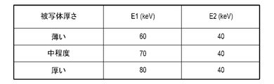
- FIG. 7 is a diagram exemplifying a configuration of a table holding the values of the radiation energies E 1 and E 2 , and the storage unit 108 holds a table in which information on a subject is associated with different radiation energies for each substance. ing.
- the subject information includes information on the body thickness of the subject or information on the thickness of the substance.
- the value of the radiation energy according to the body thickness of the subject is stored as the subject information. If the body thickness of the subject can be obtained, different radiation energies E 1 and E 2 corresponding to the body thickness of the subject can be obtained.
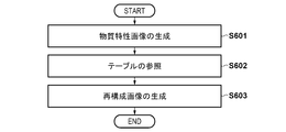
- step S601 the generation unit 110 generates a substance separation image that is a substance characteristic image. This processing is similar to the processing of step S201 of the flowchart described in step S2 of FIG.
- the reconstruction unit 111 sets different radiation energies E 1 and E 2 for each substance corresponding to the information on the subject to be imaged by referring to the table stored in the storage unit 108.
- the body thickness of the subject may be obtained based on the photographing information, may be selected by a technician from the operation unit 107, or may be the thickness of each substance (for example, fat The thickness of the subject may be estimated from the thickness).
- step S603 the reconstructing unit 111 generates a reconstructed image (Xproc) from the material separation image (fat and bone thickness image), which is the material characteristic image generated in step S601, based on [Equation 3].
- the single radiation energies E 1 and E 2 used for generating the reconstructed image (Xproc) are the values set by referring to the table in step S602.
- the display control unit 116 causes the monitor 106 (display unit) to display the reconstructed image (Xproc) generated by the reconstructing unit 111.
- the display control unit 116 displays a reconstructed image (Xproc) and displays a scroll bar on the monitor 106 (display unit) as a user interface (UI) for continuously changing the settings of different radiation energies E 1 and E 2 . .
- UI user interface
- the reconstruction unit 111 acquires attenuation characteristic information corresponding to the radiation energies E 1 and E 2 changed by operating the user interface (scroll bar) with reference to FIG. 4 to generate a reconstructed image (Xproc). Can be.
- the display control unit 116 causes the monitor 106 (display unit) to display a reconstructed image (Xproc) generated based on the changed radiation energy.
- the display control unit 116 can display the value held in the table on the monitor 106 (display unit) as a recommended value.
- the technician can change the value of the radiation energy from the operation unit 107 with reference to the value displayed on the monitor 106 (display unit) so as to emphasize a desired substance.
- the reconstructing unit 111 acquires the line attenuation coefficients corresponding to the radiation energies E 1 and E 2 changed by the input from the operation unit 107 from FIG. 4, generates a reconstructed image (Xproc), and displays the reconstructed image (Xproc).
- the present embodiment by storing the values of the radiation energies E 1 and E 2 in a table in advance, it is possible to generate a good reconstructed radiation image without executing the processing of the optimization method. It becomes.
- a drawing speed of about 15 FPS is required, so that the processing of this embodiment can be applied to processing that requires real-time processing such as during fluoroscopic imaging.
- the present embodiment it is possible to reconstruct a radiation image by setting radiation energy for each of a plurality of substances without using a tomographic image even in general imaging or fluoroscopic imaging, and to enhance an image of a specific substance. Can be easily obtained.
- the third embodiment a configuration in which the values of the radiation energies E 1 and E 2 corresponding to the effective atomic numbers Z 1 and Z 2 are obtained by analysis will be described.
- the configuration example of the radiation imaging system 100 according to the third embodiment of the present invention is the same as the radiation imaging system 100 of FIG. 1 described in the first embodiment, and the radiation imaging system 100 includes a radiation generation device 104 and a radiation source. 101, an FPD 102 (radiation detecting device), and an information processing device 120.
- the description of the same parts as those of the first embodiment will be omitted, and different parts will be described.
- the control unit 105 divides the low-energy radiation distribution information and the high-energy high-energy radiation distribution information from a plurality of radiation images obtained by a single radiation irradiation from the radiation generator 104.
- the generation unit 110 When acquired, the generation unit 110 generates a material characteristic image for a plurality of substances included in the radiation image based on the obtained result.
- the generation unit 110 generates an image (substance separated image) separated into a plurality of substances from the low-energy radiation distribution information and the high-energy radiation distribution information as a substance characteristic image.
- the generation unit 110 can generate an image indicating the thickness or density distribution of a plurality of substances as a separated image (substance separated image).
- the reconstruction unit 111 sets different radiation energies (monochromatic radiation energies) for the positions of a plurality of substances and generates a reconstructed image based on the different radiation energies.
- the position of the substance includes a pixel or a region formed by a plurality of pixels in the radiation image. That is, the reconstruction unit 111 can set different radiation energy for each pixel as the position of the substance. Alternatively, the reconstruction unit 111 can set different radiation energies for each region constituted by a plurality of pixels as the position of the substance.
- the reconstruction unit 111 generates, as a reconstructed image, a monochromatic radiation image obtained by multiplying an attenuation coefficient (mass attenuation coefficient) at radiation energy different for each position of a plurality of substances by a surface density of each pixel.
- the attenuation coefficient is information of a plurality of substances and information associated with radiation energy
- the information of the plurality of substances includes an effective atomic number of the substance or a substance separated into a plurality of substances.
- Information (such as the thickness of the substance).
- the analysis unit 112 creates an energy table that associates a plurality of substances with different radiation energies.
- the analysis unit 112 creates an energy table that associates a single radiation energy with the effective atomic number Zeff i of each pixel as radiation energy (reconstruction energy) used when generating a reconstructed image.
- the reconstruction unit 111 sets different radiation energies for each position of a plurality of substances with reference to the energy table.
- the control unit 105 stores the radiation image captured by the FPD 102 in the storage unit 108 and transfers the radiation image to the image processing unit 109.
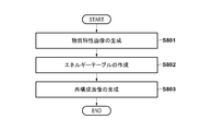
- step S801 the generation unit 110 generates a substance separation image or a substance identification image as a substance characteristic image. Specifically, the generation unit 110 described in the first embodiment a high-energy radiation image as shown in FIG. 3A and a low-energy radiation image as shown in FIG. A substance separation image is generated based on Expression 1 and Expression 2.
- FIG. 9 is a diagram showing the relationship between the logarithmic ratio of the low-energy and high-energy radiation distribution information and the effective atomic number Z. As shown in FIG. 9, the relationship between the logarithmic ratio and the effective atomic number Z is tabulated in advance. And stored in the storage unit 108.
- the generation unit 110 specifies the effective atomic number Z corresponding to the logarithmic ratio for each pixel (the position of a pixel or an area configured by a plurality of pixels) by referring to the table, thereby obtaining the effective atomic number image Z eff . Can be generated.
- the generation unit 110 can generate an area density image D indicating the distribution of the area density of the substance corresponding to the effective atomic number, based on the effective atomic number image Z eff .
- the generation unit 110 replaces the mass attenuation coefficient, the low-energy radiation distribution information ( XL ), and the high-energy radiation, instead of the equations [1] and [2] described in the first embodiment.
- the effective atomic number image Z and the area density image D can be obtained.
- step S802 the analysis unit 112 creates an energy table that associates a plurality of substances with different radiation energies.
- FIG. 11 is a diagram illustrating an energy table that associates an effective atomic number with a single radiation energy.
- the vertical axis indicates radiation energy (E)
- the horizontal axis indicates effective atomic number (Z eff ).
- the effective atomic numbers Z 1 and Z 2 are the effective atomic numbers corresponding to the first ratio (for example, the lower 5%) from the effective atomic numbers in the effective atomic number image, and the effective atomic numbers from the upper one.
- An effective atomic number corresponding to the ratio of 2 (for example, the top 5%) can be used.
- FIG. 13A is a diagram schematically illustrating the relationship between radiation energy and noise
- 13a and 13b in FIG. 13A are diagrams illustrating Comparative Example 1 and Comparative Example 2
- 13c is a diagram illustrating processing according to the present embodiment. is there.
- first substance e.g., bone
- second substance e.g., fat
- CNR ratio of noise to relative contrast
- the analyzing unit 112 sets the information (thickness or density) of each substance after the energy substance separation on the horizontal axis of the energy table, and sets a single radiation energy corresponding to the information of each substance on the vertical axis of the energy table. Should be set to.
- the reconstruction unit 111 refers to the energy table, sets different radiation energies (monochromatic radiation energies) for the positions of the plurality of substances, and generates a reconstructed image based on the different radiation energies.
- the reconstructing unit 111 generates a reconstructed radiation image (X proc ) from the effective atomic number image (Z eff ) and the surface density image (D) generated in step S801 based on the following equation (5).
- the reconstructed radiation image ( Xproc ) is also referred to as a reconstructed image or a reconstructed radiation image.
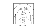
- FIG. 13B is a diagram illustrating the effect of the third embodiment.
- FIG. 13B shows the correspondence (attenuation characteristic information) between the radiation energy and the mass attenuation coefficient
- a waveform 1301 is a waveform indicating an attenuation characteristic of a first substance (for example, bone)
- a waveform 1302 is a waveform.
- 6 is a waveform showing attenuation characteristics of a second substance (for example, fat).
- the attenuation characteristic information differs for each of a plurality of substances (effective atomic numbers).
- a reconstructed radiographic image may be crushed by black or white. Therefore, based on the effective atomic number of each substance, radiation energy is set for each pixel (the position of a pixel or an area constituted by a plurality of pixels) to reconstruct a radiation image. For example, a high energy is set for a pixel indicating an effective atomic number of a second substance (eg, fat), and a low energy is set for a pixel indicating an effective atomic number of a first substance (eg, bone). Is set to generate the reconstructed image (X proc ), it becomes possible to obtain a reconstructed radiographic image in which the first substance is emphasized and the influence of the second substance is reduced.
- a high energy is set for a pixel indicating an effective atomic number of a second substance (eg, fat)
- a low energy is set for a pixel indicating an effective atomic number of a first substance (eg, bone).
- the monitor 106 can display a radiographic image (digital image) received by the control unit 105 from the FPD 102 or an image processed by the image processing unit 109.
- the display control unit 116 causes the monitor 106 (display unit) to display the reconstructed image (X proc ) generated by the reconstructing unit 111.
- the present embodiment it is possible to reconstruct a radiation image by setting different radiation energies for each of the positions of a plurality of substances without using a tomographic image even in general imaging or fluoroscopic imaging. Can be easily obtained.
- the reconstruction unit 111 reconstructs the radiation image (X) based on [Equation 5] from the effective atomic number image (Z eff ) and the surface density image (D) generated in step S801. proc )), but is not limited to this example.
- the reconstruction unit 111 performs the reconfiguration based on the result. It is also possible to generate a composed radiation image (X proc ).
- the energy table 11 when creating the energy table of FIG. 11, the value of the radiation energy E 1, E 2 obtained from the storage unit 108, the energy table 11 based on the radiation energy E 1, E 2 obtained Will be described.
- the configuration of the present embodiment has an advantageous effect when a reconstructed image is generated based on an energy spectrum that a technician wants to emphasize during still image capturing, rather than the real-time property required during fluoroscopic capturing.
- the generation unit 110 generates a material identification image that is a material characteristic image.
- the substance identification image includes, for a plurality of substances included in the subject, an effective atomic number image indicating an effective atomic number distribution and an area density image indicating an area density distribution.
- the analysis unit 112 creates an energy table based on the radiation energies E 1 and E 2 set from the operation unit 107.
- the analysis unit 112 can create an energy table based on radiation energy changed according to imaging information among a plurality of radiation energies set in advance from the operation unit 107.
- the analysis unit 112 calculates the effective atomic numbers Z 1 , Z 2 and the radiation energies E 1 , E 2 based on the radiation energies E 1 , E 2 acquired by referring to the table changed according to the imaging conditions and the like, for example.
- An associated energy table (FIG. 11) is created.
- the reconstruction unit 111 uses the effective atomic number image (Z eff ) and the surface density image (D), which are the material identification images generated in step S801, based on the expression (3) to form the reconstruction image (X proc ).
- the reconstructing unit 111 refers to the energy table (FIG. 11) created in step S802 and converts the effective atomic number Z eff i and the radiation energy E i in each pixel. Generate a reconstructed image (X proc ) based on the corresponding mass attenuation coefficient ⁇ i .
- the effective atomic number of each pixel can be specified based on the effective atomic number image (Z eff )
- the corresponding radiation energy can be set for each pixel position or for each region composed of a plurality of pixels. it can.
- the mass attenuation coefficient ⁇ (Z, E) at the effective atomic number Z and the radiation energy E can be obtained with reference to the table in the storage unit 108.
- the reconstructing unit 111 calculates information on the effective atomic number of the substance and the attenuation coefficient corresponding to the attenuation coefficient corresponding to the radiation energy (mass attenuation coefficient ⁇ (Z, E)) and a plurality of information.
- a reconstructed image (X proc ) is generated based on the area density image D indicating the distribution of the area density of the substance.
- the display control unit 116 causes the monitor 106 (display unit) to display the reconstructed image (X proc ) generated by the reconstructing unit 111.
- the display control unit 116 displays a reconstructed image (X proc ) and also displays a scroll bar on the monitor 106 (display unit) as a user interface (UI) for continuously changing settings of different radiation energies E 1 and E 2. Let it.
- the analysis unit 112 associates different effective atomic numbers Z 1 , Z 2 with the radiation energies E 1 , E 2 based on the radiation energies E 1 , E 2 changed by operating the user interface (scroll bar). (FIG. 11).
- a reconstructed radiation image can be generated based on an energy spectrum that a technician wants to emphasize when capturing a still image.
- the present embodiment it is possible to reconstruct a radiation image by setting different radiation energies for each of the positions of a plurality of substances without using a tomographic image even in general imaging or fluoroscopic imaging. Can be easily obtained.
- 100 radiation imaging system
- 101 radiation source
- 102 FPD (radiation detection device)
- 104 radiation generation device
- 105 control unit
- 106 monitor (display unit)
- 107 operation unit
- 108 storage unit
- 109 Image processing unit
- 110 generation unit
- 112 analysis unit
- 120 information processing device
Landscapes
- Engineering & Computer Science (AREA)
- Health & Medical Sciences (AREA)
- Life Sciences & Earth Sciences (AREA)
- Medical Informatics (AREA)
- Physics & Mathematics (AREA)
- Molecular Biology (AREA)
- General Health & Medical Sciences (AREA)
- High Energy & Nuclear Physics (AREA)
- Nuclear Medicine, Radiotherapy & Molecular Imaging (AREA)
- Optics & Photonics (AREA)
- Biomedical Technology (AREA)
- Radiology & Medical Imaging (AREA)
- Heart & Thoracic Surgery (AREA)
- Pathology (AREA)
- Surgery (AREA)
- Animal Behavior & Ethology (AREA)
- Biophysics (AREA)
- Public Health (AREA)
- Veterinary Medicine (AREA)
- General Physics & Mathematics (AREA)
- Theoretical Computer Science (AREA)
- Quality & Reliability (AREA)
- Computer Vision & Pattern Recognition (AREA)
- Spectroscopy & Molecular Physics (AREA)
- Data Mining & Analysis (AREA)
- Multimedia (AREA)
- Human Computer Interaction (AREA)
- Artificial Intelligence (AREA)
- Evolutionary Biology (AREA)
- Evolutionary Computation (AREA)
- General Engineering & Computer Science (AREA)
- Bioinformatics & Computational Biology (AREA)
- Bioinformatics & Cheminformatics (AREA)
- Physiology (AREA)
- Apparatus For Radiation Diagnosis (AREA)
Abstract
L'invention porte sur un appareil de photographie par rayonnement (100) qui comprend : une unité de génération (110) qui génère des images de propriété de substance concernant une pluralité de substances comprises dans des images de rayonnement photographiées au moyen de différentes énergies de rayonnement ; et une unité de reconstruction (111) qui définit différentes énergies de rayonnement pour la pluralité respective de substances et génère une image de reconstruction sur la base d'images de rayonnement monochromatiques des substances respectives en fonction des différentes énergies de rayonnement.
Priority Applications (1)
| Application Number | Priority Date | Filing Date | Title |
|---|---|---|---|
| US17/127,302 US11813095B2 (en) | 2018-06-27 | 2020-12-18 | Radiation imaging apparatus, radiation imaging method, and non-transitory computer-readable storage medium |
Applications Claiming Priority (4)
| Application Number | Priority Date | Filing Date | Title |
|---|---|---|---|
| JP2018122354A JP7144988B2 (ja) | 2018-06-27 | 2018-06-27 | 放射線撮影装置、放射線撮影方法およびプログラム |
| JP2018122352A JP7144987B2 (ja) | 2018-06-27 | 2018-06-27 | 放射線撮影装置、放射線撮影方法およびプログラム |
| JP2018-122352 | 2018-06-27 | ||
| JP2018-122354 | 2018-06-27 |
Related Child Applications (1)
| Application Number | Title | Priority Date | Filing Date |
|---|---|---|---|
| US17/127,302 Continuation US11813095B2 (en) | 2018-06-27 | 2020-12-18 | Radiation imaging apparatus, radiation imaging method, and non-transitory computer-readable storage medium |
Publications (1)
| Publication Number | Publication Date |
|---|---|
| WO2020003744A1 true WO2020003744A1 (fr) | 2020-01-02 |
Family
ID=68985616
Family Applications (1)
| Application Number | Title | Priority Date | Filing Date |
|---|---|---|---|
| PCT/JP2019/018337 Ceased WO2020003744A1 (fr) | 2018-06-27 | 2019-05-08 | Appareil de photographie par rayonnement, procédé de photographie par rayonnement, et programme |
Country Status (2)
| Country | Link |
|---|---|
| US (1) | US11813095B2 (fr) |
| WO (1) | WO2020003744A1 (fr) |
Families Citing this family (7)
| Publication number | Priority date | Publication date | Assignee | Title |
|---|---|---|---|---|
| JP7169853B2 (ja) | 2018-11-09 | 2022-11-11 | キヤノン株式会社 | 画像処理装置、放射線撮影装置、および画像処理方法 |
| JP7397593B2 (ja) | 2019-07-23 | 2023-12-13 | キヤノン株式会社 | 放射線撮像装置、画像取得方法およびプログラム |
| JP7246281B2 (ja) | 2019-08-02 | 2023-03-27 | キヤノン株式会社 | 画像処理装置およびその制御方法、放射線撮影装置、プログラム |
| JP7619821B2 (ja) | 2021-02-09 | 2025-01-22 | キヤノン株式会社 | 情報処理装置、放射線撮影システム、情報処理方法およびプログラム |
| JP2023181859A (ja) * | 2022-06-13 | 2023-12-25 | キヤノン株式会社 | 放射線撮像装置、情報処理装置、情報処理方法及びプログラム |
| JP2024025211A (ja) | 2022-08-10 | 2024-02-26 | キヤノン株式会社 | 放射線撮像装置、放射線撮像システム、制御装置、放射線撮像装置の制御方法、および、放射線撮像装置を制御するためのプログラム |
| JP2024046543A (ja) * | 2022-09-22 | 2024-04-03 | 富士フイルム株式会社 | 放射線画像処理装置、方法およびプログラム |
Citations (4)
| Publication number | Priority date | Publication date | Assignee | Title |
|---|---|---|---|---|
| JP2011172803A (ja) * | 2010-02-25 | 2011-09-08 | Ge Medical Systems Global Technology Co Llc | X線ct装置 |
| JP2014061286A (ja) * | 2012-08-30 | 2014-04-10 | Toshiba Corp | X線ct装置、画像処理装置、及び画像処理方法 |
| WO2016147844A1 (fr) * | 2015-03-19 | 2016-09-22 | 株式会社日立製作所 | Dispositif de tomodensitométrie à rayons x et procédé de création d'image multi-énergie |
| JP2016193921A (ja) * | 2010-07-12 | 2016-11-17 | ジーイー・ヘルスケア・アクスイェ・セルスカプ | 低造影剤濃度及び/又は低放射線量でのx線イメージング |
Family Cites Families (53)
| Publication number | Priority date | Publication date | Assignee | Title |
|---|---|---|---|---|
| US8115784B2 (en) * | 2008-11-26 | 2012-02-14 | General Electric Company | Systems and methods for displaying multi-energy data |
| JP5315157B2 (ja) | 2009-07-27 | 2013-10-16 | キヤノン株式会社 | 情報処理装置、ライン状ノイズ低減処理方法、及びプログラム |
| JP5543194B2 (ja) | 2009-12-24 | 2014-07-09 | キヤノン株式会社 | 情報処理装置、処理方法及びプログラム |
| JP6214128B2 (ja) | 2010-11-22 | 2017-10-18 | キヤノン株式会社 | 画像処理装置、画像処理方法、及び記憶媒体 |
| JP5725930B2 (ja) | 2011-03-31 | 2015-05-27 | ジーイー・メディカル・システムズ・グローバル・テクノロジー・カンパニー・エルエルシー | 画像生成装置およびx線ct装置並びにプログラム |
| JP5814621B2 (ja) | 2011-05-24 | 2015-11-17 | キヤノン株式会社 | 撮像装置及びその制御方法、並びに、撮像システム |
| JP6073616B2 (ja) * | 2011-09-28 | 2017-02-01 | 東芝メディカルシステムズ株式会社 | X線ct装置、画像処理装置及びプログラム |
| JP6122269B2 (ja) | 2011-12-16 | 2017-04-26 | キヤノン株式会社 | 画像処理装置、画像処理方法、及びプログラム |
| JP5950840B2 (ja) | 2012-03-16 | 2016-07-13 | キヤノン株式会社 | 放射線撮像装置及び撮像システム |
| JP5986526B2 (ja) | 2012-04-06 | 2016-09-06 | キヤノン株式会社 | 放射線撮像装置、その制御方法及び放射線撮像システム |
| JP6162937B2 (ja) | 2012-08-31 | 2017-07-12 | キヤノン株式会社 | 放射線撮像装置、その制御方法および制御プログラム |
| JP6312401B2 (ja) | 2012-11-30 | 2018-04-18 | キヤノン株式会社 | 画像処理装置、画像処理方法、及びプログラム |
| JP6041669B2 (ja) | 2012-12-28 | 2016-12-14 | キヤノン株式会社 | 撮像装置及び撮像システム |
| JP5986524B2 (ja) | 2013-02-28 | 2016-09-06 | キヤノン株式会社 | 放射線撮像装置および放射線撮像システム |
| JP2014168205A (ja) | 2013-02-28 | 2014-09-11 | Canon Inc | 放射線撮像装置、放射線検査装置、信号の補正方法およびプログラム |
| JP5934128B2 (ja) | 2013-02-28 | 2016-06-15 | キヤノン株式会社 | 放射線撮像装置及び放射線撮像システム |
| JP6016673B2 (ja) | 2013-02-28 | 2016-10-26 | キヤノン株式会社 | 放射線撮像装置および放射線撮像システム |
| JP6161346B2 (ja) | 2013-03-19 | 2017-07-12 | キヤノン株式会社 | 撮像システム |
| US20140361189A1 (en) | 2013-06-05 | 2014-12-11 | Canon Kabushiki Kaisha | Radiation imaging system |
| JP6238577B2 (ja) | 2013-06-05 | 2017-11-29 | キヤノン株式会社 | 放射線撮像装置及び放射線撮像システム |
| JP6376783B2 (ja) | 2014-03-12 | 2018-08-22 | キヤノン株式会社 | 乳房断層撮影装置および制御方法 |
| JP6355387B2 (ja) | 2014-03-31 | 2018-07-11 | キヤノン株式会社 | 撮像装置及び撮像システム |
| US9737271B2 (en) | 2014-04-09 | 2017-08-22 | Canon Kabushiki Kaisha | Radiation imaging apparatus and control method of the same |
| JP6362421B2 (ja) | 2014-05-26 | 2018-07-25 | キヤノン株式会社 | 放射線撮像装置、その制御方法およびプログラム |
| JP6494204B2 (ja) | 2014-07-17 | 2019-04-03 | キヤノン株式会社 | 放射線撮像装置及び放射線撮像システム |
| JP6385179B2 (ja) | 2014-07-18 | 2018-09-05 | キヤノン株式会社 | 放射線撮像装置及びその駆動方法 |
| JP6391388B2 (ja) | 2014-09-24 | 2018-09-19 | キヤノン株式会社 | 放射線撮像装置 |
| JP6497912B2 (ja) | 2014-12-01 | 2019-04-10 | キヤノン株式会社 | 画像処理装置、放射線撮影システム、制御方法、及びプログラム |
| US9460485B2 (en) * | 2014-12-11 | 2016-10-04 | General Electric Company | Systems and methods for guided de-noising for computed tomography |
| JP6525579B2 (ja) | 2014-12-22 | 2019-06-05 | キヤノン株式会社 | 放射線撮像装置及び放射線撮像システム |
| JP2016178533A (ja) | 2015-03-20 | 2016-10-06 | キヤノン株式会社 | 放射線撮像装置及び放射線撮像システム |
| JP6573377B2 (ja) | 2015-07-08 | 2019-09-11 | キヤノン株式会社 | 放射線撮像装置、その制御方法及びプログラム |
| JP6573378B2 (ja) | 2015-07-10 | 2019-09-11 | キヤノン株式会社 | 放射線撮像装置、その制御方法及びプログラム |
| JP6674222B2 (ja) | 2015-10-09 | 2020-04-01 | キヤノン株式会社 | 放射線撮像装置および放射線撮像装置の制御方法 |
| JP6643871B2 (ja) | 2015-11-13 | 2020-02-12 | キヤノン株式会社 | 放射線撮像装置およびフォトンカウンティングの方法 |
| JP6643909B2 (ja) | 2016-01-27 | 2020-02-12 | キヤノン株式会社 | 放射線撮像装置、その制御方法及びプログラム |
| JP6700828B2 (ja) | 2016-02-10 | 2020-05-27 | キヤノン株式会社 | 放射線撮像装置、その駆動方法及び撮像システム |
| JP6871717B2 (ja) | 2016-11-10 | 2021-05-12 | キヤノン株式会社 | 放射線撮像装置、放射線撮像システムおよび放射線撮像方法 |
| JP2018110794A (ja) | 2017-01-13 | 2018-07-19 | キヤノン株式会社 | 情報処理装置、放射線撮像装置、情報処理方法およびプログラム |
| JP6974948B2 (ja) | 2017-02-10 | 2021-12-01 | キヤノン株式会社 | 放射線撮像装置および放射線撮像方法 |
| JP6727155B2 (ja) * | 2017-02-27 | 2020-07-22 | 株式会社日立製作所 | 画像処理装置、x線ct装置及び画像処理方法 |
| WO2019012846A1 (fr) | 2017-07-10 | 2019-01-17 | キヤノン株式会社 | Dispositif d'imagerie par rayonnement et système d'imagerie par rayonnement |
| JP6934769B2 (ja) | 2017-07-28 | 2021-09-15 | キヤノン株式会社 | 放射線撮像装置および放射線撮像方法 |
| JP6912965B2 (ja) | 2017-08-04 | 2021-08-04 | キヤノン株式会社 | 放射線撮像装置、放射線撮像システムおよび放射線撮像装置の作動方法 |
| JP7038506B2 (ja) | 2017-08-25 | 2022-03-18 | キヤノン株式会社 | 放射線撮像装置、放射線撮像システムおよび放射線撮像装置の作動方法 |
| JP7080025B2 (ja) | 2017-09-01 | 2022-06-03 | キヤノン株式会社 | 情報処理装置、情報処理方法およびプログラム |
| JP6882135B2 (ja) | 2017-10-06 | 2021-06-02 | キヤノン株式会社 | 画像処理装置、画像処理方法及びプログラム |
| JP2019072190A (ja) | 2017-10-16 | 2019-05-16 | キヤノン株式会社 | 放射線撮影装置及びその動作方法、並びに、プログラム |
| JP7067912B2 (ja) | 2017-12-13 | 2022-05-16 | キヤノン株式会社 | 放射線撮像装置および放射線撮像システム |
| JP7245001B2 (ja) | 2018-05-29 | 2023-03-23 | キヤノン株式会社 | 放射線撮像装置および撮像システム |
| JP7093233B2 (ja) | 2018-06-07 | 2022-06-29 | キヤノン株式会社 | 放射線撮影装置、放射線撮影方法およびプログラム |
| JP7313194B2 (ja) * | 2019-05-30 | 2023-07-24 | キヤノン株式会社 | 画像処理装置、画像処理方法及びプログラム |
| JP7378245B2 (ja) | 2019-08-29 | 2023-11-13 | キヤノン株式会社 | 放射線検出装置、その制御方法及び放射線撮像システム |
-
2019
- 2019-05-08 WO PCT/JP2019/018337 patent/WO2020003744A1/fr not_active Ceased
-
2020
- 2020-12-18 US US17/127,302 patent/US11813095B2/en active Active
Patent Citations (4)
| Publication number | Priority date | Publication date | Assignee | Title |
|---|---|---|---|---|
| JP2011172803A (ja) * | 2010-02-25 | 2011-09-08 | Ge Medical Systems Global Technology Co Llc | X線ct装置 |
| JP2016193921A (ja) * | 2010-07-12 | 2016-11-17 | ジーイー・ヘルスケア・アクスイェ・セルスカプ | 低造影剤濃度及び/又は低放射線量でのx線イメージング |
| JP2014061286A (ja) * | 2012-08-30 | 2014-04-10 | Toshiba Corp | X線ct装置、画像処理装置、及び画像処理方法 |
| WO2016147844A1 (fr) * | 2015-03-19 | 2016-09-22 | 株式会社日立製作所 | Dispositif de tomodensitométrie à rayons x et procédé de création d'image multi-énergie |
Also Published As
| Publication number | Publication date |
|---|---|
| US20210118193A1 (en) | 2021-04-22 |
| US11813095B2 (en) | 2023-11-14 |
Similar Documents
| Publication | Publication Date | Title |
|---|---|---|
| WO2020003744A1 (fr) | Appareil de photographie par rayonnement, procédé de photographie par rayonnement, et programme | |
| KR101689867B1 (ko) | 영상을 처리하는 방법, 이를 수행하는 영상처리장치 및 의료영상시스템 | |
| NL2002313C2 (en) | System and method for extracting features of interest from an image. | |
| KR101479212B1 (ko) | 엑스선 영상 장치 및 엑스선 영상 생성 방법 | |
| US9949706B2 (en) | Image-processing device, radiographic imaging system, image-processing program, and image-processing method | |
| JP5124363B2 (ja) | エネルギーサブトラクション処理装置、方法、およびプログラム | |
| KR101747300B1 (ko) | 영상을 처리하는 방법, 이를 수행하는 영상처리장치 및 의료영상시스템 | |
| JP7080025B2 (ja) | 情報処理装置、情報処理方法およびプログラム | |
| JP2017143943A (ja) | 放射線画像処理装置、方法およびプログラム | |
| JP7093233B2 (ja) | 放射線撮影装置、放射線撮影方法およびプログラム | |
| JP7246281B2 (ja) | 画像処理装置およびその制御方法、放射線撮影装置、プログラム | |
| EP3612095A1 (fr) | Correction de durcissement de faisceau en imagerie en champ sombre par rayons x | |
| JP7169853B2 (ja) | 画像処理装置、放射線撮影装置、および画像処理方法 | |
| KR20160139163A (ko) | 엑스선 장치 및 그 제어방법 | |
| JP2017080343A (ja) | 放射線撮像システム、放射線画像の情報処理装置、放射線画像の情報処理方法、及び、そのプログラム | |
| JP6566887B2 (ja) | 放射線画像処理装置、方法およびプログラム | |
| CN110881993A (zh) | X射线ct装置、医用图像处理装置以及x射线ct系统 | |
| CN102871682A (zh) | 使用多能量x射线源采集计算机断层数据的系统和方法 | |
| WO2020241110A1 (fr) | Dispositif de traitement des images, procédé de traitement des images et programme | |
| EP1253557A1 (fr) | Procédé et processus pour générer une image avec contraste augmentée | |
| JP2017080342A (ja) | 放射線撮像システム、放射線画像の情報処理装置、放射線画像の情報処理方法、及び、そのプログラム | |
| JP7144988B2 (ja) | 放射線撮影装置、放射線撮影方法およびプログラム | |
| JP7144987B2 (ja) | 放射線撮影装置、放射線撮影方法およびプログラム | |
| JP7458750B2 (ja) | 画像処理装置、放射線撮影装置、画像処理方法及びプログラム | |
| KR101860145B1 (ko) | 광자계수기반 디지털 단층영상합성 장치, 시스템에서의 이중에너지 영상화방법 및 이를 이용한 시스템 |
Legal Events
| Date | Code | Title | Description |
|---|---|---|---|
| 121 | Ep: the epo has been informed by wipo that ep was designated in this application |
Ref document number: 19826374 Country of ref document: EP Kind code of ref document: A1 |
|
| NENP | Non-entry into the national phase |
Ref country code: DE |
|
| 122 | Ep: pct application non-entry in european phase |
Ref document number: 19826374 Country of ref document: EP Kind code of ref document: A1 |