WO2020003786A1 - Garment accommodating implement - Google Patents
Garment accommodating implement Download PDFInfo
- Publication number
- WO2020003786A1 WO2020003786A1 PCT/JP2019/019367 JP2019019367W WO2020003786A1 WO 2020003786 A1 WO2020003786 A1 WO 2020003786A1 JP 2019019367 W JP2019019367 W JP 2019019367W WO 2020003786 A1 WO2020003786 A1 WO 2020003786A1
- Authority
- WO
- WIPO (PCT)
- Prior art keywords
- frame
- middle frame
- lower frame
- frame body
- connection portion
- Prior art date
- Legal status (The legal status is an assumption and is not a legal conclusion. Google has not performed a legal analysis and makes no representation as to the accuracy of the status listed.)
- Ceased
Links
Images


Classifications
-
- A—HUMAN NECESSITIES
- A47—FURNITURE; DOMESTIC ARTICLES OR APPLIANCES; COFFEE MILLS; SPICE MILLS; SUCTION CLEANERS IN GENERAL
- A47G—HOUSEHOLD OR TABLE EQUIPMENT
- A47G25/00—Household implements used in connection with wearing apparel; Dress, hat or umbrella holders
- A47G25/14—Clothing hangers, e.g. suit hangers
- A47G25/20—Clothing hangers, e.g. suit hangers with devices for preserving the shape of the clothes
-
- A—HUMAN NECESSITIES
- A47—FURNITURE; DOMESTIC ARTICLES OR APPLIANCES; COFFEE MILLS; SPICE MILLS; SUCTION CLEANERS IN GENERAL
- A47G—HOUSEHOLD OR TABLE EQUIPMENT
- A47G25/00—Household implements used in connection with wearing apparel; Dress, hat or umbrella holders
- A47G25/14—Clothing hangers, e.g. suit hangers
- A47G25/40—Collapsible hangers
Definitions
- the present invention relates to a clothing storage device.
- both left and right portions are configured to be laterally foldable with respect to the center portion of the hanger, and extend downward from the center portion of the hanger.
- a shaping hanger provided with a frame portion (hanger body portion 19) configured to be vertically foldable has been proposed.
- a hanger configured to be vertically foldable there is also known a hanger disclosed in Patent Document 2 below.
- Patent Document 3 describes an auxiliary plate used when folding clothes.
- the auxiliary plate has a connecting plate 20 connected to the left and right of the main plate 10 and a central lower plate 40 connected below the main plate 10.
- a garment is arranged on each of these plates, and the connecting plate 20 and the central lower plate 40 can be folded so as to overlap the central portion of the garment on the main plate 10 together with the portion of the garment arranged thereon. Is done.
- the hanger described in Patent Document 2 and the auxiliary plate described in Patent Document 3 can fold even a clothing of a certain thickness, but the regulating force at the time of folding the clothing is weak.
- the folded portion of the clothes is displaced or the clothes are wrinkled.
- the hanger described in Patent Literature 2 since it is simply inserted inside the central portion of the garment, there is no structure for guiding the horizontal folding, and the vertical connecting portion is also formed by a belt. Therefore, the folded portion is not stable.
- the auxiliary plate described in Patent Literature 3 the clothing is simply folded with the clothing placed thereon, and the clothing cannot be supported and guided from the inside. Therefore, the function of guiding the clothing during folding is extremely high. It is weak, and there is a possibility that the folding mode may be disturbed.
- an object of the present invention is to provide a clothing storage device that can be compactly stored while suppressing wrinkles and the like by appropriately folding the clothing according to the mode of the clothing to be applied.
- a clothing storage device of the present invention includes a middle frame having a middle supporting upper edge arranged on the left and right middle sides inside the upper part of the garment, and a middle frame inside the upper part of the garment.
- An outer support upper edge disposed outside the left and right sides of the side support upper edge and an outer support side edge disposed inside the side of the garment, and a first connector is provided on the left and right sides of the middle frame.
- the first connector is a middle frame side connection portion connected to the side portion of the middle frame body so as to change a connection angle, and a connection angle is changeable with respect to the side frame body. It is preferable to have a side frame-side connection portion connected to the first frame, and a connection portion connecting the middle frame-side connection portion and the side frame-side connection portion via a first interval.
- a lower frame having an upper portion connected to the lower portion of the middle frame so as to be expandable and foldable via a second connector.
- the second connector is connected to the lower portion of the middle frame body so that the connection angle can be changed, and the second connector is connected to the upper portion so that the connection angle can be changed.
- the vertical length of the side frame is larger than the horizontal width of the side frame.
- the vertical length of the side frame is preferably 1.5 times or more the horizontal width of the side frame.
- the length of the side frame in the up-down direction is at least twice the width of the side frame in the left-right direction.
- the vertical length of the left and right side frames is in the range of 80% to 120% of the vertical length of the middle frame.
- the upper edge of the side frame body is configured to have a position and a shape that forms a gentle curved upper edge shape of the hanger together with the support shape of the upper portion of the middle frame body.
- 80% or more of the length range of the side frame in the vertical direction overlaps with the length range of the middle frame in the vertical direction.
- the third connecting member has a lower frame side connection portion connected to the side portion of the lower frame body so as to be capable of changing a connection angle, and changes a connection angle with respect to the lower frame body.
- a lower frame-side connection portion operatively connected to the lower frame-side connection portion; and a connection portion connecting the lower frame-side connection portion and the lower frame-side connection portion via a third space.
- the second interval is larger than the third interval.
- the lower frame has the same width in the left-right direction as the middle frame. Further, it is desirable that the lower frame has the same width in the left-right direction as the side frame.
- the first connecting member generates a holding force for maintaining an angular posture with respect to the middle frame and the side frame when the middle frame and the side frame are in a developed state. It is preferable that it is comprised as follows. In this case, it may be configured to generate a holding force for maintaining the posture when the middle frame and the side frame are in the folded state.
- the first connector changes a connection angle of the middle frame side connection portion and the side frame side connection portion
- the direction connecting the middle frame side connection portion and the side frame side connection portion is from a posture along a direction in which the middle frame body and the side frame body face each other to a posture inclined with respect to the facing direction. It is desirable to be configured to be able to migrate. At this time, the direction connecting the middle frame side connection portion and the side frame side connection portion is changed from the posture along the direction in which the middle frame body and the side frame body face each other, with respect to the facing direction. It is further desirable to be configured to be able to shift to a posture inclined to either of both sides.
- another clothing storage device of the present invention is a middle frame which is arranged inside the upper part of the garment, and which is a part arranged at least on the left and right inside in the upper part of the garment.
- An upper frame portion including a body, and an upper frame portion which is provided at a lower portion of the middle frame body and is expandably and foldably connected to the lower portion of the middle frame body via a second connector, and is a portion arranged at least on the left and right middle sides.
- a lower frame portion including:
- the second connecting member is connected to the lower portion of the middle frame so that the connection angle is changeable, and the connection angle is changeable to the upper portion of the lower frame.
- the upper frame preferably includes the middle frame, and preferably includes the left and right side frames together with the middle frame.
- the middle frame member included in the upper frame portion may include both the component of the middle frame member and the component portion of the side frame member (not foldable) integrally.
- the lower frame preferably includes the lower frame, and preferably includes the left and right lower frames together with the lower frame.
- the lower frame included in the lower frame may include both the component of the lower frame and the component of the lower frame integrally (not foldable).
- the second connecting member generates a holding force for maintaining an angular posture with respect to the middle frame and the lower frame when the middle frame and the lower frame are in an expanded state. It is preferable that it is comprised as follows.
- the holding mechanism may be configured to generate a holding force for maintaining an angular posture with respect to the middle frame and the lower frame. .
- the middle frame-side connection portion and the lower frame-side connection portion change a connection angle
- the direction connecting the middle frame side connection portion and the lower frame side connection portion is from a posture along a direction in which the middle frame body and the lower frame body face each other to a posture inclined with respect to the facing direction. It is desirable to be configured to be able to migrate. At this time, the direction connecting the middle frame side connection portion and the lower frame side connection portion is changed from the posture along the direction in which the middle frame body and the lower frame body face each other, with respect to the facing direction. It is further desirable to be configured to be able to shift to a posture inclined to either of both sides.
- the middle frame includes a hook attached to the center of the upper portion, and the hook has a feeding position protruding upward from the upper portion and a storage position stored inside the middle frame. It is desirable to be configured to be switchable. In addition, it is preferable that at least one of the first connector and the second connector is configured to be able to fold each frame body in either direction. In addition, it is preferable that at least one of the first connector and the second connector is configured such that the connecting portion is bendable.
- clothing is hung on the upper part (the middle support upper edge and the outer support upper edge) of the middle frame and the side frame in the unfolded mode, and the left and right side portions of the clothing are joined together with the left and right side frames.
- the garment By folding the garment, the garment can be folded in the lateral direction while maintaining the first interval by the first connector, and the garment can be held.
- the garment by folding the lower part of the garment upward together with the lower frame, the garment can be folded in the vertical direction while maintaining the second interval by the second connector, and held. Therefore, it is possible to provide a clothing storage device that can be compactly stored while suppressing disorder of the folding mode by enabling the clothing to be properly folded in accordance with the mode of the applied clothing.
- the second interval is larger than the first interval, even when the garment is folded vertically and horizontally, the thickness of the garment increases, so that an orderly folding mode can be reliably realized.
- the outer supporting side edge of the side frame can be formed in a wide range in the vertical direction. Since the side portion can be firmly supported and guided from the inside over a wide range when the side portion is folded, the garment can be prevented from being disturbed in the folding manner, and can be properly folded.
- the left and right sides of the clothing are connected to the left and right side frames over a wide range in the vertical direction.
- Folding the garment laterally while holding the first space by the first connector and the third space by the third connector by folding back together with the lower frame body, and holding this Can be. Therefore, the entire left and right sides up to the lower part of the garment can be neatly folded in the lateral direction, and the lower part thus folded can be folded back together with the lower frame and the lower frame, so that Clothing can be folded more precisely and orderly and compactly.
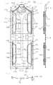
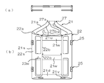
- the front view (a), the right side view (b), and the bottom view showing the mode in which the lower frame and the lower frame of the clothing storage device of the first embodiment are folded on the middle frame and the side frames.
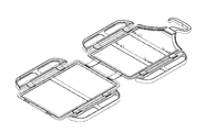
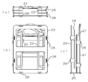
- FIG. 2 is a perspective view of a developed mode of the first embodiment.
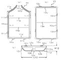
- FIG. 1 It is the top view (a) and front view (b) of the mode which the middle frame body and the side frame body of 2nd Embodiment folded. It is a front view of the whole developed mode of a 2nd embodiment.
- FIG. It is the top view (a), the front view (b), and the right side view (c) which show the folded aspect of 2nd Embodiment.
- the clothing storage device 10 of the present embodiment is connected to a middle frame 11 and left and right side portions of the middle frame 11 via a first connecting tool 15. And left and right side frame members 12 and a lower frame member 13 connected to a lower portion of the middle frame member 11 via a second connecting member 16.
- the middle frame 11 and the left and right side frames 12 connected via the first connecting member 15 correspond to the above-described upper frame in the present embodiment.
- the above-mentioned middle frame 11, side frame 12, and lower frame 13 (and lower frame 14 described later) are integrally formed of synthetic resin or the like.
- the first connector 15 and the second connector 16 (and a third connector 18 described later) are also integrally formed of synthetic resin or the like.
- each part is made of a material such as a hard resin having a certain degree of rigidity, but a flexible material such as rubber can be used as long as the support performance of the clothes CL can be secured. .
- the middle frame 11 is a frame (a frame that supports the clothes CL from the inside) having a rectangular planar shape as a whole.
- the sides of the left and right side portions 11s and the lower portion 11d are linear, while the sides of the upper portion 11u are formed in a mountain shape.
- a middle supporting upper edge 11a is formed on the left and right middle sides inside the upper part CLa of the garment CL.
- the middle supporting upper edge 11a has a shape that is wider in the front-rear direction than the other plate-like portions of the middle frame body 11, and gradually descends from the middle to the left and right in a concave curve shape. It has a form corresponding to the shoulder of a hanger with a contour that goes down.
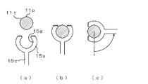
- the middle support upper edge 11a is divided at the center, and the base 17a of the hook 17 is fitted to the divided portion so that the base 17a of the hook 17 has a horizontal axis shown in FIG. (See (a)).
- the locking portion 17b of the hook 17 is attached so as to be rotatable around an axis perpendicular to the base 17a. Further, an opening 17c is provided in the base 17a so that a tie or the like can be inserted and hung.
- a projection shaft 17d is formed at the lower end of the locking portion 17b, and this projection shaft 17d fits into a receiving hole 17e of a base 17a formed by overlapping the halves 17A and 17B.
- a pivoting support structure that is rotatable around a vertical axis of the locking portion 17b with respect to the base 17a is configured.
- a band-like horizontal portion 11 w connecting the left and right side portions 11 s.
- two horizontal portions 11w are formed vertically.
- the horizontal portion 11w is configured so that slacks or the like can be hung thereon.
- each frame means that the garment CL is supported from the inside, and there is no meaning related to other structures and shapes. Therefore, the term itself of each frame does not represent a specific structure or shape.
- the side frame 12 includes a linear inner portion 12 s on the side of the middle frame 11 and an arcuate outer portion 12 o on the opposite side to the middle frame 11.
- An upper portion of the outer portion 12o is provided with an outer support upper edge 12a extending obliquely downward and outward with a convex curve along an extension of the middle support upper edge 11a.
- the left and right inclined portions of the middle support upper edge 11a and the support surfaces of the outer support upper edges 12a of the left and right side frame bodies 12 are provided with a structure for preventing slip in a direction along the contour. For example, a surface uneven structure may be formed.
- An outer supporting side edge 12b extending linearly downward is provided at the center of the outer portion 12o.
- an outer support lower edge 12c is provided below the outer portion 12o and extends with a convex curved contour toward the inside obliquely downward.
- the outer support upper edge 12a and the outer support lower edge 12c are symmetrical, so that the overall shape of the outer portion 12o is also vertically symmetrical.
- the side frame 12 is provided with a horizontal portion 12w that connects an intermediate portion of the inner portion 12s and an intermediate portion of the outer portion 12o.
- the length L12 in the up-down direction is larger than the width W12 in the left-right direction.
- the length L12 is 1.5 times or more the width W12.
- the length L12 is twice or more (about 3.5 times) the width W12. This is for widening the vertical support range of the outer support side edge 12b.
- the left and right side portions CLb of the garment CL can be supported and guided by the outer support side edge 12b over a wide vertical support range. This is one of the features of the present embodiment in which a conventional hanger or hanger-type storage device is not provided.
- the center middle frame 11 and the left and right side frames 12, 12 are viewed in the left and right width directions, and are shown in a developed state shown in FIG. 1 (hereinafter, simply referred to as a "development state") and in FIG. They are connected by the first connecting member 15 so as to be in any of the folded modes (hereinafter, simply referred to as “folded modes”).
- the first connector 15 includes a middle frame-side connection portion 15a fitted to a connection shaft 11t having a vertical axis provided on the left and right side portions 11s of the middle frame body 11 shown in FIG.
- the distance between the middle frame side connection portion 15a and the side frame side connection portion 15b in the first connection portion 15, that is, the axis of the connection shaft 11t and the axis of the connection shaft 12t. Is the first interval G15.
- This first interval G15 is a value suitable for folding the left and right side portions CLb of the garment CL.
- the middle frame portion 11 and the side frame portion 12 each have two connection shafts 11t and 12t in the vertical direction, and are connected to each other by the first connection tool 15 at each of these portions.
- the connecting portion 15c of the first connecting member 15 is made of a flexible material such as a rubber material, the distance G15 may be slightly increased or decreased. This is the same for the second connector 16 and the third connector 18 described later.
- connection shafts 11t, 12t, the middle frame side connection portion 15a, and the side frame side connection portion 15b are fitted to each other and can be relatively rotated. Make up the structure.
- FIG. 4 shows only a connection structure (shaft support structure) between the connection shaft 11t and the middle frame side connection portion 15a, but a connection structure (shaft support structure) between the connection shaft 12t and the side frame side connection portion 15b. ) Is the same.
- the middle frame side connection portion 15a has a shaft support structure that rotatably supports the connection shaft 11t.
- the middle frame side connection portion 15a and the side frame side connection portion 15b are opposed to each other in the extending direction of the connecting portion 15c (the direction connecting the middle frame side connection portion 15a and the side frame side connection portion 15b).
- An opening that opens in the direction is provided, and through this opening, the middle frame side connection part 15a and the side frame side connection part 15b and the connection shafts 11t and 12t are configured to be detachable.
- the middle frame side connection portion 15a and the side frame side connection portion 15b and the connection shafts 11t and 12t are in a state of being rotatably fitted at the time of mounting.
- connection shafts 11t and 12t are fitted into the respective connection portions through the openings by the middle frame side connection portions 15a and the side frame side connection portions 15b being elastically deformed mainly in a manner to increase or decrease the opening width of the openings. (Snap-in) or withdrawal.
- connection structure shaft support structure
- a rib (convex streak) 11p is formed at a predetermined angular position on the outer peripheral surface of the connection shaft 11t, and the inside of the middle frame side connection portion 15a is formed.
- a concave groove 15g is formed at a corresponding angular position on the peripheral surface, and when the middle frame side connection portion 15a and the connecting shaft 11t have a predetermined angular relationship, the rib 11p and the concave groove 15g are fitted, and the angle The position is configured such that a predetermined holding force is generated around the axis.
- generates holding force between the side frame side connection part 15b and the connection shaft 12t is also the same.
- connection structure may be configured to generate a predetermined holding force at a predetermined angle.
- a holding force for holding an angle is generated between both connecting portions 15 a and 15 b of the first connecting tool 15 and the connecting shafts 11 t and 12 t.
- the first connecting member 15 is configured such that the connecting portion 15 c is substantially in the left-right direction (middle frame) between the middle frame 11 and the side frame 12.
- the posture is along the frame plane of the body 11).
- connection portions 15a and 15b may be configured to be smoothly rotatable with respect to the connection shafts 11t and 12t in the entire rotation range. This is the same in connection portions 16a, 16b and 18a, 18b described later.
- the upper portion 11u of the middle frame body 11 is configured to have a T-shaped cross section in which an outer portion bulges in the front-rear direction with respect to an inner portion configured in a plate shape, and as a result, has an upper edge portion formed to be wide. .
- the middle supporting upper edge 11a is configured as an upper surface of the upper edge portion.
- the middle supporting upper edge 11a is configured to have a surface shape that becomes a convex curved surface along the front-rear direction.
- the inner portion 12s of the side frame 12 is entirely formed in a plate shape, whereas the outer portion 12o arranged on the side opposite to the middle frame 11 in the unfolded state is a plate-shaped inner portion.
- the outer portion is configured to have a T-shaped cross section that bulges in the front-rear direction, and as a result, has a wide side edge.
- the outer supporting upper edge 12a, the outer supporting side edge 12b, and the outer supporting lower edge 12c are configured as outer surfaces of the side edge 12o.
- the outer support upper edge 12a, the outer support side edge 12b, and the outer support lower edge 12c are configured as mutually continuous surfaces from above to below.
- the outer support upper edge 12a may be shaped to protrude laterally beyond the outer support side edge 12b so that the outer support upper edge 12a can be inserted into the inside of the sleeve CLc from the shoulder opening of the garment CL like the left and right ends of the hanger. Good.
- the outer support side edge 12b is arranged inside the side part CLb below the shoulder opening of the sleeve part CLc of the garment CL. Accordingly, when the left and right side portions CLb of the garment CL are folded, the side portions CLb of the garment CL can be firmly guided from the inside, so that an orderly folding mode can be realized. Further, in the illustrated example, since the side frames 12 are formed symmetrically in the front-rear direction, the left and right side frames can be shared. In the illustrated example, the side frame 12 has a shape in which the outer support upper edge 12a and the outer support lower edge 12c do not protrude from the outer support side edge 12b, and thus is shared with the lower frame 14 described later. It becomes possible.
- the appearance of the clothing storage device 10 of the present embodiment is shown in a perspective view of FIG.
- the clothing storage device 10 of the present embodiment has symmetrical shapes on both front and back sides in the perspective view of FIG. Parts other than the hook 17 have symmetrical shapes and structures on both the left and right sides.
- connection shaft 11v having a horizontal axis is formed at a lower portion 11d of the middle frame 11.
- two connection shafts 11t are formed in the lower portion 11d.
- the connection shaft 11v is fitted to the middle frame side connection portion 16a of the second connection tool 16, and is rotatably connected.
- the second connecting member 16 includes the above-described middle frame side connection portion 16a, a lower frame side connection portion 16b connected to a lower frame body 13 described later, and the above described middle frame side connection portion.
- a connecting portion 16c for connecting the portion 16a and the lower frame side connecting portion 16b is provided.
- the distance between the middle frame side connection portion 16a and the lower frame side connection portion 16b in the second connection portion 16, that is, the distance between the axis of the connection shaft 11v and the axis of the connection shaft 13v is the second space G16. It has become.
- the second interval G16 is a value suitable for vertically folding the lower part CLd of the garment CL on the upper part CLa thereof in a manner in which the left and right side parts CLb of the garment CL are folded together with the side frame 12. Is done.
- the second interval G16 is larger than the first interval G15.
- the first interval G16 is preferably in the range of 1.6 to 2.4 times the first interval G15, and particularly preferably 2 times.
- the lower portion 11d of the middle frame portion 11 and the upper portion 13u of the lower frame portion 13 are provided with connecting shafts 11v and 13v at two locations in the left-right direction, respectively.
- the second connecting member 16 is different only in the length of the connecting portion 16c.
- the structure of the middle frame side connecting portion 16a and the lower frame side connecting portion 16b is the same as the connecting structure of the first connecting member 15 described above. It is formed in the same manner as the fitting structure, and the same applies to the structure for providing the above-mentioned holding force. In particular, in the deployed state shown in FIGS. 1 and 2, it is desirable that the holding force for holding the angular posture of the middle frame 11 and the lower frame 13 via the second connecting member 16 is generated.
- the lower frame 13 is a rectangular frame as a whole.
- each side of the upper portion 13u, the left and right side portions 13s, and the lower portion 13d is formed in a plate shape having a linear band-shaped planar shape.
- the lower part 13d may be formed in a mountain shape like the upper part 11u of the middle frame 11, and the hook 17 may be provided.
- a connection shaft 13v having a horizontal axis is provided on the upper portion 13u and the lower portion 13d.
- two connection shafts 13v are formed in each of the upper portion 13u and the lower portion 13d.
- the connection shaft 13v provided on the upper portion 13u is fitted to the lower frame side connection portion 16b of the second connection tool 16, and is rotatably connected.
- the lower frame body 13 has a symmetrical form on each of the front and back sides, the left and right sides, and the upper and lower sides.
- the lower frame 13 is connected to the lower frames 14 arranged on the left and right sides, respectively, via the third connecting member 18.
- the lower frame 13 and the left and right lower frames 14 connected via the third connector 18 correspond to the lower frame in the present embodiment.
- a connecting shaft 13t having a vertical axis is formed on each of the left and right side portions 13s, and the connecting shaft 13t is connected to the lower frame side connecting portion 18a of the third connecting member 18.
- the lower frame 14 includes a straight inner portion 14s and an arcuate outer portion 14o.
- a connection shaft 14t having a vertical axis is provided on the inner portion 14s, and the connection shaft 14t is rotatably connected by a lower frame side connection portion 18b of the third connection member 18.
- the outer portion 14o is provided with an outer support upper edge 14a, an outer support side edge 14b, and an outer support lower edge 14c similar to the side frame 12.
- the lower frame 14 has the same shape and structure as the side frame 12 completely.
- the lower frame 14 has a shape in which the outer support upper edge 14a and the outer support lower edge 14c do not protrude from the outer support side edge 14b, similarly to the side frame 12.
- the outer portion 14o (the outer support upper edge 14a, the outer support side edge 14b, and the outer support lower edge 14c) fits inside the side portion CLb of the garment CL.
- connection structure and the fitting structure of the third connector 18 are completely the same as those of the first connector 15, and the lower frame-side connection portion 18a, the lower frame-side connection portion 18b, and the connection portion are the same. 18c.
- the distance between the lower frame side connection portion 18a and the lower frame side connection portion 18b in the third connection portion 18, that is, the distance between the axis of the connection shaft 13t and the axis of the connection shaft 14t (the third G18) is configured the same as the first interval G15. Therefore, the second interval G16 is larger than the third interval G18.
- the entire width of the lower frame 13 in the left-right direction may be configured to be slightly different from the entire width of the middle frame 11 in the left-right direction (for example, to be slightly smaller).
- the lower frame portion may be constituted by only the lower frame member 13 to which the left and right lower frame members 14 are not connected.
- the clothing CL is hung on the upper portion 11 u of the middle frame 11 and the upper portion of the side frame 12 of the clothing storage device 10.
- the clothing CL (in the illustrated example, an outerwear, a coat, or the like) is hung on the clothing storage device 10 with its front facing rearward. That is, in FIG. 1, the back surface of the clothing CL is in a posture facing forward. However, the clothing CL may be hung on the clothing storage device 10 with the front of the clothing CL facing forward.
- the clothing storage device 10 In the state of FIG. 1, the clothing storage device 10 is in the unfolded state, and the middle support upper edge 11 a of the middle frame 11 and the outer support upper edge 12 a of the side frame 12 are arranged inside the upper CLa of the clothing CL, The clothes CL are supported from the inside. As a result, the clothes CL can be hung by the hooks 17.
- the outer supporting side edge 12b of the side frame 12 and the outer supporting side edge 14b of the lower frame 14 are arranged inside the side part CLb of the garment CL.
- the sleeve CLc is not directly supported from the inside. However, by projecting the outer support upper edge 12a of the side frame 12 outward from the outer support side edge 12b, the protruding portion is formed by the clothing CL.
- the lower part CLd of the garment CL is arranged at a position corresponding to the lower part 13d of the lower frame 13 in the illustrated example, but the positional relationship (up and down position) between the lower part CLd and the lower part 13d is arbitrary. Since the hook 17 is basically not used when being stored in a bag or a case, the hook 17 is rotated downward about the support shaft 11y as shown in FIG. (The inside of the middle frame 11).
- the left and right side portions CLb of the garment CL are folded forward to form a lateral folding mode.
- the side part CLb of the garment CL is folded onto the middle frame 11 together with the side frames 12 and the lower frame 14 arranged inside.
- the side CLb is connected to the side frame 12 and the lower side. While being guided from the inside by the side frame 14, it is orderly folded.
- the first connecting member 15 has an intermediate frame side connecting portion 15a and a side frame side connecting portion 15b, respectively, as shown in FIG. 2 (c). It rotates with respect to 11t and 12t, and each becomes a bent state.
- the side frame 12 and the lower frame 14 are different from the conventional structure in that the length L12 (L14) in the up-down direction is larger than the width W12 (W14) in the left-right direction, particularly 1.5 times or more, or 2 times.
- the outer support side edge 12b (14b) is raised and lowered while being dimensioned to accommodate the inner frame 11 and the side frame 12 (the lower frame 13 and the lower frame 14) inside the garment CL. It can be provided in a wide range of directions. Therefore, it is possible to fold the clothes CL orderly while the side parts CLb of the clothes CL are firmly guided from the inside. That is, it is possible to fold without breaking the fold by the guidance of the side frame 12 and the lower frame 14.
- the angle ⁇ shown in FIG. 2C (the frame plane of the middle frame body 11) relates to the first connector 15 and the third connector 18 that function to form the folding mode.
- the extending direction of the connecting portions 15b and 18b (the direction connecting the middle frame side connecting portion 15a, the lower frame side connecting portion 18a to the side frame side connecting portion 15b, and the lower frame side connecting portion 18b).
- the angle of intersection between them can be set to any angle in the range from 90 degrees to another angle smaller than 90 degrees.
- the angle ⁇ is movable within a range of at least 20 to 160 degrees.
- the interval between the directions in which the middle frame 11 and the side frame 12 (or the lower frame 13 and the lower frame 14) face each other is as described above.
- the first interval G15 (the third interval G18) is the maximum.
- the angle ⁇ is smaller than 90 degrees, the interval in the facing direction becomes smaller than the first interval G15 (the third interval G18) due to the inclination of the connecting portion 15c (18c).
- the thickness of the structure is also reduced.
- the side frame body 12 (lower frame body 14) is disposed outward with respect to the middle frame body 11 (lower frame body 13) by an amount corresponding to the inclination of the connecting portion 15c (18c).
- the angle ⁇ is slightly increased in the left-right direction.
- the gap in the facing direction is smaller than the first gap G15 (third gap G18), and the thickness of the folded structure is also reduced. I do.
- the side frame 12 (lower frame 14) is arranged inward with respect to the middle frame 11 (lower frame 13) by an amount corresponding to the inclination of the connecting portion 15c (18c).
- the space in the left-right direction of the portion to be arranged is slightly reduced.
- the angle ⁇ is changed according to the thickness of the cloth of the clothing CL or the size of each part of the clothing CL, and the like, so that the clothing storage device 10 and the entire clothing CL are changed.
- the thickness and width in the left-right direction can be adjusted. For example, it is possible to make the overall dimensions (thickness in the front-rear direction and width in the left-right direction) as compact as possible in accordance with the clothes CL.
- the angle between the installation plane of the side frame 12 and the extending direction of the connecting portions 15c and 18c is 0 degree in the unfolded state shown in FIG. 1 and the horizontal folding shown in FIG.
- the angle value is around 90 degrees at least close to 90 degrees.
- the angle range in which the connection angle can be changed must be a range including at least the above-mentioned 0 degree to a value around 90 degrees.
- connection angle ranges of the connection angles in the connection portions 15a, 18a, 15b, 18b are as follows: the middle frame 11 or the lower frame 13, the side frame 12, or the lower frame in the folding mode.
- the connection angle can be variably set within a range of 0 to 180 degrees by not causing interference between the connection portions 14 or 14 and the connection portions 15c and 18c. It is.
- the interference can be avoided by reducing the thickness, increasing the interval, and reducing the width in the inward and outward directions of the adjacent regions of the members other than the connection portions 15a, 15b, 18a, and 18b. For example, in the deployment mode shown in FIG.
- the inner edge of the side portion 11 s of the middle frame 11 is formed as shown by a dotted line to reduce the width of the side 11 s in the inward and outward directions, and the inner portion 12 s of the side frame 12.
- the inner frame body 11 and the inner frame body 11 are formed by a method of reducing the width of the inner edge and removing the corners, or a method of reducing the thickness of the side portion 11 s and the inner portion 12 s. Interference in the thickness direction of the frame 12 can be avoided.
- the lower part CLd of the garment CL is folded upward to form a vertical folding mode.
- the lower CLd is folded onto the middle frame 11 and the side frame 12 together with the lower frame 13 and the lower frame 14 arranged inside.
- the overall thickness of the clothing CL and the clothing storage device 10 is increased, but the second interval G16 of the second coupling tool 16 is larger than the first interval G15 (third interval G18) ( Preferably, it is 1.6 to 2.4 times, particularly 2 times, so that it can be folded without any trouble.
- the first connector 15, the second connector 16, and the third connector 18 are shared, and the first interval G15, the second interval G16, the third May be set to the same value.
- the angle ⁇ is relatively largely shifted before and after 90 degrees, and the extending direction of the connecting portions 15c and 18c is folded.
- the inner frame 11 and the side frame 12, or the lower frame 13 and the lower frame 14 are configured to be inclined from the direction in which they face each other, and viewed in the facing direction.
- the substantial interval is made smaller than G15 or G18, and in the second connecting member 16, the angle ⁇ is set relatively to 90 degrees or close to 90 degrees, and the inclination of the extending direction with respect to the facing direction is eliminated.
- the angle ⁇ shown in FIG. 3B (the direction along the frame plane of the middle frame body 11 and the extending direction of the connecting portion 16b (the middle frame side connection portion 16a and the lower frame side connection
- the angle of intersection with the direction connecting the portions 16b) can be set to any angle in the range from an angle larger than 90 degrees to another angle smaller than 90 degrees. ing.
- the angle ⁇ is 90 degrees
- the interval in the direction in which the middle frame 11 and the lower frame 13 face each other is the second interval G16, which is the maximum.
- the angle ⁇ is smaller than 90 degrees, the interval in the facing direction is smaller than the second interval G16, so that the thickness of the folded structure also decreases.
- the lower frame 13 is disposed below the middle frame 11 by an amount corresponding to the inclination of the connecting portion 16c, the vertical arrangement space of the portion on the lower side of the clothing CL is small. Increase. Further, when the angle ⁇ is larger than 90 degrees, the interval in the facing direction is smaller than the second interval G16, so that the thickness of the folded structure is also reduced. On the other hand, since the lower frame 13 is disposed above the middle frame 11 by an amount corresponding to the inclination of the connecting portion 16c, the space in the vertical direction of the lower portion of the garment CL is reduced although it is small. I do.
- the angle ⁇ is changed according to the thickness of the cloth of the clothing CL or the size of each part of the clothing CL, and the like, so that the clothing storage device 10 and the entire clothing CL are changed.
- the thickness and length in the vertical direction can be adjusted. For example, it is possible to make the overall dimensions (the thickness in the front-rear direction and the length in the vertical direction) as compact as possible in accordance with the clothing CL.
- the respective connection angles of the connection portions 16 a and 16 b provided on both sides of the connection portion 16 c (the installation plane of the middle frame 11 or the lower frame 13 and the connection 16c is 0 degree in the unfolded state shown in FIGS. 1 and 2, and is at least close to 90 degrees in the longitudinally folded state shown in FIG. Angle values before and after degrees.
- the angle range in which the connection angle can be changed must be a range including at least the above-mentioned 0 degree to a value around 90 degrees.
- the changeable angle range of the connection angle in each of the connection portions 16a and 16b is determined between the middle frame 11 and the side frame 12 and the lower frame 13 and the lower frame 14 in the vertical folding mode.
- connection angle can be variably set in the range of 0 to 180 degrees by preventing the interference between them or the connection portion 16c from occurring.
- the interference can be avoided by reducing the thickness, increasing the interval, and reducing the width in the inward and outward directions of the region adjacent to each member other than the connection portions 16a and 16b. For example, the vertical width and the thickness of the lower portion 11d of the middle frame 11 shown in FIG. 1 are reduced and the vertical width and the thickness of the upper portion 13u of the lower frame 13 are reduced.
- the middle frame 21 (upper portion 21u, side portion 21s, lower portion 21d, middle support upper edge 21a, connecting shafts 21t, 21v, horizontal portion 21w), side frame 22 (inner portion 22s, outer portion).
- each frame is different from the first embodiment in that it does not have a thick upper edge shape or an outer edge shape bulging in the front-rear direction, and is formed in a plate shape as a whole.
- the first connector 25, the second connector 26, and the third connector 28 are connected to each of the connecting portions (the middle frame side connecting portion 25a, the side frame side connecting portion 25b, the middle frame side connecting portion 26a, Each opening of the frame-side connection portion 26b, the lower frame-side connection portion 28a, and the lower frame-side connection portion 28b) opens in a direction along the extending direction of the connection portion as in the first embodiment. In contrast to this, the opening is opened in a direction orthogonal to the extending direction of the connecting portions 25c, 26c, 28c.
- the third connector 28 has the same shape and structure as the first connector 25.
- the clothing CL can be folded vertically and horizontally with the clothing CL attached.
- the angle ⁇ and ⁇ by changing the angle ⁇ and ⁇ , the overall thickness and size can be adjusted, and the overall dimensions at the time of storage can be made compact according to the clothing CL. The same is true.
- the entirety in the folded state is stored in a bag, case, or bag (not shown) so that the clothing CL can be easily stored and carried. Can be.
- the specific size is not particularly limited, but, for example, it is possible to put almost all the clothes CL in a plane shape of A3 size.
- the clothes CL can be returned to the original form by a simple operation, and the clothes storage devices 10 and 20 disposed inside can be suspended as they are.
- the clothing storage device of the present invention is not limited to the illustrated example described above, and it goes without saying that various changes can be made without departing from the spirit of the present invention.
- the middle support upper edges 11a, 21a are provided on the upper portions 11u, 21u of the middle frame members 11, 21, and the outer support upper edges 12a are provided on the outer portions 12o, 22o of the side frame members 12, 22.
- the clothes storage device according to the present invention is arranged such that the inner supporting upper edges 11a, 21a and the outer supporting It merely shows that the edges 12a, 22a are used and that the outer support side edges 12b, 22b are used inside the side part CLb of the garment CL. Therefore, according to the present invention, the middle supporting upper edges 11a and 21a, the outer supporting upper edges 12a and 22a, and the outer supporting side edges 12b and 22b have a form having a thickness in the front-rear direction as shown in the drawing. It is not required that the middle frame bodies 11 and 21 have the shape of a chevron as shown in the figure.
- the middle frame bodies 11 and 21 may be flat upper portions 13 u such as the lower frame bodies 13 and 23. 23u may be provided.
- each of the connecting members 15, 25, 16, 26, 18, and 28 includes a connecting shaft 11t, 21t, 12t, 22t, 13t, 23t, 14t, which is formed on the side of each frame.
- Each of the connecting portions 15a, 15b, 16a, 16b, 18a, and 18b rotatably supports the 24t, 11v, 21v, 13v, and 23v.
- a shaft supporting portion is provided on each frame. It may be formed so that a connecting shaft is formed at a connecting portion of each connecting tool.
- connection portions 15a, 15b, 16a, 16b, 18a, and 18b are rotatably connected to the frames 11, 12, 13, and 14, respectively.
- Each connection part may be connected to each frame in a manner that allows a connection angle to be changed. Therefore, for example, each of the connection portions may be a bendable bending portion.
- the clothing storage devices 10 and 20 are not limited to outerwear (clothes) as shown in the figure, but also include shirts, coats, kimonos (furisode, yukata, etc.), underwear, work clothes, swimwear, pajamas, gowns, robes, dresses, and the like. It can also be used for various types of clothing. Further, it may be used for other clothes such as pants, skirts, tights, and scarves. For example, pants (trousers) are hung on the horizontal portions 11w and 21w, and the legs of the pants are further lowered with the horizontal portions 11w and 21w, the lower portions 11d and 21d, and the horizontal portions 13w and 23w or the lower portions 13d and 23d. By passing in between, it can be held alone or inside other outfits such as jacket jackets.
- the middle frame 11, the side frame 12, the lower frame 13, the lower frame 14, or the upper frame and the lower frame are each configured in a frame shape capable of supporting clothing from the inside as a whole. What is necessary is just a thing,
- the planar shape and thickness distribution, or the inside structure of the said horizontal part 11w, 21w, 12w, 22w, etc. are not limited.
Landscapes
- Holders For Apparel And Elements Relating To Apparel (AREA)
Abstract
Description
本発明は衣類収納具に関する。 The present invention relates to a clothing storage device.
従来から、衣類を折畳可能に構成した種々の器具が提案されている。例えば、以下の特許文献1には、ハンガーの中央部分に対して左右の両側部分(ハンガー肩受部10,11)を横方向に折り畳み可能に構成するとともに、ハンガーの中央部分から下方へ延在し、縦方向に折り畳み可能に構成された枠体部(ハンガー胴部19)を備えた整形ハンガーが提案されている。また、縦方向に折り畳み可能に構成されたハンガーとしては、以下の特許文献2に開示されたものも知られている。
器具 Conventionally, various devices configured to fold clothes have been proposed. For example, in
また、以下の特許文献3には、衣類を折り畳む際に用いる補助板が記載されている。この補助板は、主板10の左右に連接板20を連結するとともに、主板10の下方に中央下板40を連結したものである。これらの各板の上に衣類を配置し、連接板20や中央下板40をその上に配置された衣類の部分とともに主板10上の衣類の中央部分に重ねるように折りたたむことができるように構成される。
Patent Document 3 below describes an auxiliary plate used when folding clothes. The auxiliary plate has a connecting
ところで、上記特許文献1に記載された折り畳み可能なハンガーにおいては、衣類を掛けて吊り下げることができるとともに衣類とともに縦横に折り畳むことができるものの、ワイシャツなどの薄手の衣類に用いることを想定しているため、スーツの上着やコートなどの厚手の衣類に用いると、回転軸の近傍に布地が挟まることにより連結部分を完全に折り畳むことができなくなり、衣類をコンパクトに収納することができなくなる場合があるといった問題がある。
By the way, in the foldable hanger described in
一方、上記特許文献2に記載されたハンガーや特許文献3に記載された補助板では、或る程度の厚みの衣類であっても折り畳むことができるが、衣類に対する折り畳み時の規制力が弱いため、衣類の折り畳み箇所がずれてしまったり、衣類にしわが寄ってしまったりするという問題がある。例えば、特許文献2に記載されたハンガーでは、単に衣類の中央部内側に挿入されるだけであるため、横方向の折り畳みを案内する構造自体が存在せず、縦方向の連結部もベルトで構成されるため、折り畳み箇所が安定しない。また、特許文献3に記載された補助板では、単にその上に衣類を載せた状態で折り畳むだけであり、衣類を内側から支持、案内することができないため、折り畳み時の衣類の案内機能がきわめて弱く、折り畳み態様の乱れが生ずる虞がある。
On the other hand, the hanger described in
そこで、本発明の課題は、適用する衣類の態様に応じて衣類を的確に折り畳み可能とすることにより、皺などを抑制しつつコンパクトに収納可能な衣類収納具を提供することにある。 Accordingly, an object of the present invention is to provide a clothing storage device that can be compactly stored while suppressing wrinkles and the like by appropriately folding the clothing according to the mode of the clothing to be applied.
上記課題を解決するために、本発明の衣類収納具は、衣類の上部の内部において左右の中側に配置される中側支持上縁を備える中枠体と、衣類の上部の内部において前記中側支持上縁の左右の外側に配置される外側支持上縁及び衣類の側部の内側に配置される外側支持側縁を備え、前記中枠体の左右の側部に第1の連結具を介して展開可能かつ折り畳み可能にそれぞれ連結された左右の側枠体と、を具備する。ここで、前記第1の連結具は、前記中枠体の前記側部に対して接続角を変更可能に接続された中枠側接続部と、前記側枠体に対して接続角を変更可能に接続された側枠側接続部と、前記中枠側接続部と前記側枠側接続部を第1の間隔を介して連結する連結部とを有することが好ましい。 In order to solve the above-mentioned problem, a clothing storage device of the present invention includes a middle frame having a middle supporting upper edge arranged on the left and right middle sides inside the upper part of the garment, and a middle frame inside the upper part of the garment. An outer support upper edge disposed outside the left and right sides of the side support upper edge and an outer support side edge disposed inside the side of the garment, and a first connector is provided on the left and right sides of the middle frame. And left and right side frames that are connected to each other so as to be deployable and foldable. Here, the first connector is a middle frame side connection portion connected to the side portion of the middle frame body so as to change a connection angle, and a connection angle is changeable with respect to the side frame body. It is preferable to have a side frame-side connection portion connected to the first frame, and a connection portion connecting the middle frame-side connection portion and the side frame-side connection portion via a first interval.
本発明において、前記中枠体の下部に第2の連結具を介して展開可能かつ折り畳み可能に連結された上部を備える下枠体をさらに具備することが好ましい。このとき、前記第2の連結具は、前記中枠体の前記下部に対して接続角を変更可能に接続された中枠側接続部と、前記上部に対して接続角を変更可能に接続された下枠側接続部と、前記中枠側接続部と前記下枠側接続部を第2の間隔を介して連結する連結部とを有することが望ましい。この場合において、前記第2の間隔は、前記第1の間隔より大きいことがさらに好ましい。 に お い て In the present invention, it is preferable to further include a lower frame having an upper portion connected to the lower portion of the middle frame so as to be expandable and foldable via a second connector. At this time, the second connector is connected to the lower portion of the middle frame body so that the connection angle can be changed, and the second connector is connected to the upper portion so that the connection angle can be changed. It is desirable to have a lower frame side connection part, and a connecting part which connects the middle frame side connection part and the lower frame side connection part via a second space. In this case, it is more preferable that the second interval is larger than the first interval.
本発明において、前記側枠体の上下方向の長さは、前記側枠体の左右方向の幅より大きいことが好ましい。特に、前記側枠体の上下方向の長さは、前記側枠体の左右方向の幅の1.5倍以上であることが望ましい。また、前記側枠体の上下方向の長さは、前記側枠体の左右方向の幅の2倍以上であることがさらに望ましい。ここで、前記左右の側枠体の前記上下方向の長さは、前記中枠体の前記上下方向の長さの80%~120%の範囲内であることが望ましい。この場合には特に、前記側枠体の上縁は、前記中枠体の前記上部の支持形状とともにハンガーのなだらかな曲線状の上縁形状をする位置及び形状となるように構成されることが望ましい。また、前記側枠体の前記上下方向の長さ範囲の80%以上は、前記中枠体の前記上下方向の長さ範囲に対して重なることが望ましい。 In the present invention, it is preferable that the vertical length of the side frame is larger than the horizontal width of the side frame. In particular, the vertical length of the side frame is preferably 1.5 times or more the horizontal width of the side frame. It is further desirable that the length of the side frame in the up-down direction is at least twice the width of the side frame in the left-right direction. Here, it is preferable that the vertical length of the left and right side frames is in the range of 80% to 120% of the vertical length of the middle frame. In this case, particularly, the upper edge of the side frame body is configured to have a position and a shape that forms a gentle curved upper edge shape of the hanger together with the support shape of the upper portion of the middle frame body. desirable. Preferably, 80% or more of the length range of the side frame in the vertical direction overlaps with the length range of the middle frame in the vertical direction.
本発明において、前記下枠体の左右の側部に対して第3の連結具を介して展開可能かつ折り畳み可能に連結された下側枠体をさらに具備することが好ましい。ここで、前記第3の連結具は、前記下枠体の前記側部に対して接続角を変更可能に接続された下枠側接続部と、前記下側枠体に対して接続角を変更可能に接続された下側枠側接続部と、前記下枠側接続部と前記下側枠側接続部を第3の間隔を介して連結する連結部とを有する。この場合において、前記第2の間隔は、前記第3の間隔より大きいことが望ましい。また、前記下枠体は前記中枠体と同じ左右方向の幅を有することが好ましい。さらに、前記下側枠体は、前記側枠体と同じ左右方向の幅を備えることが望ましい。 に お い て In the present invention, it is preferable to further include a lower frame body that is expandably and foldably connected to the left and right sides of the lower frame body via a third connection tool. In this case, the third connecting member has a lower frame side connection portion connected to the side portion of the lower frame body so as to be capable of changing a connection angle, and changes a connection angle with respect to the lower frame body. A lower frame-side connection portion operatively connected to the lower frame-side connection portion; and a connection portion connecting the lower frame-side connection portion and the lower frame-side connection portion via a third space. In this case, it is desirable that the second interval is larger than the third interval. Preferably, the lower frame has the same width in the left-right direction as the middle frame. Further, it is desirable that the lower frame has the same width in the left-right direction as the side frame.
本発明において、前記第1の連結具は、前記中枠体と前記側枠体が展開された態様にあるときの前記中枠体及び前記側枠体に対する角度姿勢が保持される保持力を生ずるように構成されることが好ましい。この場合において、前記中枠体と前記側枠体とが折り畳まれた態様にあるときの姿勢が保持される保持力を生ずるように構成されてもよい。 In the present invention, the first connecting member generates a holding force for maintaining an angular posture with respect to the middle frame and the side frame when the middle frame and the side frame are in a developed state. It is preferable that it is comprised as follows. In this case, it may be configured to generate a holding force for maintaining the posture when the middle frame and the side frame are in the folded state.
本発明において、前記第1の連結具は、前記中枠体と前記側枠体が折り畳まれた態様において、前記中枠側接続部及び前記側枠側接続部が接続角を変更することにより、前記中枠側接続部と前記側枠側接続部とを結ぶ方向が、前記中枠体と前記側枠体とが対面する方向に沿った姿勢から、前記対面する方向に対して傾斜する姿勢に移行可能となるように構成されることが望ましい。このとき、前記中枠側接続部と前記側枠側接続部とを結ぶ方向が、前記中枠体と前記側枠体とが対面する方向に沿った姿勢から、前記対面する方向に対してその両側のいずれに傾斜する姿勢にも移行可能となるように構成されることがさらに望ましい。 In the present invention, in the aspect in which the middle frame body and the side frame body are folded, the first connector changes a connection angle of the middle frame side connection portion and the side frame side connection portion, The direction connecting the middle frame side connection portion and the side frame side connection portion is from a posture along a direction in which the middle frame body and the side frame body face each other to a posture inclined with respect to the facing direction. It is desirable to be configured to be able to migrate. At this time, the direction connecting the middle frame side connection portion and the side frame side connection portion is changed from the posture along the direction in which the middle frame body and the side frame body face each other, with respect to the facing direction. It is further desirable to be configured to be able to shift to a posture inclined to either of both sides.
次に、上記課題を解決するために、本発明の別の衣類収納具は、衣類の上部の内部に配置され、衣類の上部の内部において少なくとも左右の中側に配置される部分である中枠体を含む上枠部と、前記中枠体の下部に第2の連結具を介して展開可能かつ折り畳み可能に連結された上部を備え少なくとも左右の中側に配置される部分である下枠体を含む下枠部と、を具備する。ここで、前記第2の連結具は、前記中枠体の下部に対して接続角を変更可能に接続された中枠側接続部と、前記下枠体の上部に対して接続角を変更可能に接続された下枠側接続部と、前記中枠側接続部と前記下枠側接続部を第2の間隔を介して連結する連結部とを有することが好ましい。このとき、上記上枠部は、上記中枠体を含むことが好ましく、また、上記中枠体とともに、上記左右の側枠体を含むことが望ましい。ここで、上記上枠部に含まれる中枠体が、上記中枠体の構成部分と上記側枠体の構成部分の双方を(折り畳み可能ではなく)一体に備えるものであってもよい。一方、上記下枠部は、上記下枠体を含むことが好ましく、また、上記下枠体とともに、上記左右の下側枠体を含むことが望ましい。ここで、上記下枠部に含まれる下枠体が、上記下枠体の構成部分と上記下側枠体の構成部分の双方を(折り畳み可能ではなく)一体に備えるものであってもよい。 Next, in order to solve the above-mentioned problem, another clothing storage device of the present invention is a middle frame which is arranged inside the upper part of the garment, and which is a part arranged at least on the left and right inside in the upper part of the garment. An upper frame portion including a body, and an upper frame portion which is provided at a lower portion of the middle frame body and is expandably and foldably connected to the lower portion of the middle frame body via a second connector, and is a portion arranged at least on the left and right middle sides. And a lower frame portion including: Here, the second connecting member is connected to the lower portion of the middle frame so that the connection angle is changeable, and the connection angle is changeable to the upper portion of the lower frame. It is preferable to have a lower frame side connection portion connected to the second frame, and a connection portion connecting the middle frame side connection portion and the lower frame side connection portion via a second interval. At this time, the upper frame preferably includes the middle frame, and preferably includes the left and right side frames together with the middle frame. Here, the middle frame member included in the upper frame portion may include both the component of the middle frame member and the component portion of the side frame member (not foldable) integrally. On the other hand, the lower frame preferably includes the lower frame, and preferably includes the left and right lower frames together with the lower frame. Here, the lower frame included in the lower frame may include both the component of the lower frame and the component of the lower frame integrally (not foldable).
本発明において、前記第2の連結具は、前記中枠体と前記下枠体が展開された態様にあるときの前記中枠体及び前記下枠体に対する角度姿勢が保持される保持力を生ずるように構成されることが好ましい。この場合において、前記中枠体と前記下枠体とが折り畳まれた態様にあるときの前記中枠体及び前記下枠体に対する角度姿勢が保持される保持力を生ずるように構成されてもよい。 In the present invention, the second connecting member generates a holding force for maintaining an angular posture with respect to the middle frame and the lower frame when the middle frame and the lower frame are in an expanded state. It is preferable that it is comprised as follows. In this case, when the middle frame and the lower frame are in the folded state, the holding mechanism may be configured to generate a holding force for maintaining an angular posture with respect to the middle frame and the lower frame. .
本発明において、前記第2の連結具は、前記中枠体と前記下枠体が折り畳まれた態様において、前記中枠側接続部及び前記下枠側接続部が接続角を変更することにより、前記中枠側接続部と前記下枠側接続部とを結ぶ方向が、前記中枠体と前記下枠体とが対面する方向に沿った姿勢から、前記対面する方向に対して傾斜する姿勢に移行可能となるように構成されることが望ましい。このとき、前記中枠側接続部と前記下枠側接続部とを結ぶ方向が、前記中枠体と前記下枠体とが対面する方向に沿った姿勢から、前記対面する方向に対してその両側のいずれに傾斜する姿勢にも移行可能となるように構成されることがさらに望ましい。 In the present invention, in the aspect in which the second frame is folded in the middle frame and the lower frame, the middle frame-side connection portion and the lower frame-side connection portion change a connection angle, The direction connecting the middle frame side connection portion and the lower frame side connection portion is from a posture along a direction in which the middle frame body and the lower frame body face each other to a posture inclined with respect to the facing direction. It is desirable to be configured to be able to migrate. At this time, the direction connecting the middle frame side connection portion and the lower frame side connection portion is changed from the posture along the direction in which the middle frame body and the lower frame body face each other, with respect to the facing direction. It is further desirable to be configured to be able to shift to a posture inclined to either of both sides.
本発明において、前記中枠体は前記上部の中央に取り付けられたフックを備え、該フックは、前記上部から上方へ突出する繰り出し姿勢と、前記中枠体の内側に格納される格納姿勢とを切り替え可能に構成されることが望ましい。また、前記第1の連結具と前記第2の連結具のうちの少なくとも一方は、各枠体を表裏いずれの向きでも折り畳み可能となるように構成されることが好ましい。また、前記第1の連結具と前記第2の連結具のうちの少なくとも一方は、前記連結部が湾曲可能に構成されることが好ましい。 In the present invention, the middle frame includes a hook attached to the center of the upper portion, and the hook has a feeding position protruding upward from the upper portion and a storage position stored inside the middle frame. It is desirable to be configured to be switchable. In addition, it is preferable that at least one of the first connector and the second connector is configured to be able to fold each frame body in either direction. In addition, it is preferable that at least one of the first connector and the second connector is configured such that the connecting portion is bendable.
本発明によれば、展開態様にある中枠体と側枠体の上部(中側支持上縁と外側支持上縁)に衣類を掛け、この衣類の左右の側部を左右の側枠体とともに折り返すことにより、第1の連結具により第1の間隔を確保しつつ衣類を横方向に折り畳み、これを保持することができる。また、上記衣類の下部を下枠体とともに上方へ折り返すことにより、第2の連結具により第2の間隔を確保しつつ衣類を縦方向に折り畳み、これを保持することができる。したがって、適用する衣類の態様に応じて衣類を的確に折り畳み可能とすることにより、折り畳み態様の乱れを抑制しつつコンパクトに収納可能な衣類収納具を提供することができる。特に、第2の間隔が前記第1の間隔より大きいことにより、衣類が縦横に折り畳まれる際に厚みが増大しても、確実に整然とした折り畳み態様を実現することができる。 According to the present invention, clothing is hung on the upper part (the middle support upper edge and the outer support upper edge) of the middle frame and the side frame in the unfolded mode, and the left and right side portions of the clothing are joined together with the left and right side frames. By folding the garment, the garment can be folded in the lateral direction while maintaining the first interval by the first connector, and the garment can be held. In addition, by folding the lower part of the garment upward together with the lower frame, the garment can be folded in the vertical direction while maintaining the second interval by the second connector, and held. Therefore, it is possible to provide a clothing storage device that can be compactly stored while suppressing disorder of the folding mode by enabling the clothing to be properly folded in accordance with the mode of the applied clothing. In particular, since the second interval is larger than the first interval, even when the garment is folded vertically and horizontally, the thickness of the garment increases, so that an orderly folding mode can be reliably realized.
また、前記側枠体の上下方向の長さが左右方向の幅より大きいことにより、前記側枠体の前記外側支持側縁を上下方向の広い範囲に形成することができるため、衣類の左右の側部を折り畳む際に広範囲にわたって内側からしっかりと支持、案内することができるから、衣類に折り畳み態様の乱れが生ずることを抑制し、的確に折り畳むことができる。 Also, since the length of the side frame in the vertical direction is larger than the width in the horizontal direction, the outer supporting side edge of the side frame can be formed in a wide range in the vertical direction. Since the side portion can be firmly supported and guided from the inside over a wide range when the side portion is folded, the garment can be prevented from being disturbed in the folding manner, and can be properly folded.
さらに、下枠体の左右の側部に第3の連結具を介して下側枠体を連結する場合には、衣類の左右の側部を上下方向の広い範囲にわたって、左右の側枠体と下側枠体とともに折り返すことにより、第1の連結具により第1の間隔を確保し、第3の連結具により第3の間隔を確保しつつ、衣類を横方向に折り畳み、これを保持することができる。したがって、衣類の下部までの左右の側部全体を、整然と横方向に折り畳むことができ、さらに、そのように折り畳まれた下部を下枠体及び下側枠体と共に上部へ折り返すことができるから、衣類をさらに的確にかつ整然とコンパクトに折り畳むことができる。 Further, when the lower frame is connected to the left and right sides of the lower frame via the third connecting tool, the left and right sides of the clothing are connected to the left and right side frames over a wide range in the vertical direction. Folding the garment laterally while holding the first space by the first connector and the third space by the third connector by folding back together with the lower frame body, and holding this Can be. Therefore, the entire left and right sides up to the lower part of the garment can be neatly folded in the lateral direction, and the lower part thus folded can be folded back together with the lower frame and the lower frame, so that Clothing can be folded more precisely and orderly and compactly.
一方、中枠体を含む上枠部と下枠体を含む下枠部とを具備し、中枠体の下部と下枠体の上部とが第2の連結具を介して接続される場合には、展開態様にある上枠部と下枠部に衣類を掛け、この衣類の上下の部分を上下の上枠部と下枠部とともに折り返すことにより、第2の連結具により第2の間隔を確保しつつ衣類を縦方向に折り畳み、これを保持することができる。 On the other hand, when an upper frame portion including the middle frame and a lower frame portion including the lower frame are provided, and a lower portion of the middle frame and an upper portion of the lower frame are connected via the second connecting member, The clothes are hung on the upper frame part and the lower frame part in the deployment mode, and the upper and lower parts of the clothes are folded back together with the upper and lower upper frame parts and the lower frame part, so that the second space is provided by the second connecting member. The garment can be folded vertically while retaining it.
次に、添付図面を参照して本発明の実施形態について詳細に説明する。最初に、図1~図7を参照して、本発明に係る第1実施形態の衣類収納具について説明する。 Next, embodiments of the present invention will be described in detail with reference to the accompanying drawings. First, a clothing storage device according to a first embodiment of the present invention will be described with reference to FIGS.
(第1実施形態)
本実施形態の衣類収納具10は、図1(a)に示すように、中枠体11と、この中枠体11の左右の側部に対して第1の連結具15を介して連結された左右の側枠体12と、上記中枠体11の下部に対して第2の連結具16を介して連結された下枠体13とを備えている。第1の連結具15を介して接続された中枠体11及び左右の側枠体12は、本実施形態において、上記の上枠部に相当する。上記中枠体11、側枠体12及び下枠体13(並びに後述する下側枠体14)は、合成樹脂などによりそれぞれ一体に構成される。また、第1の連結具15、第2の連結具16(及び後述する第3の連結具18)も、合成樹脂などによりそれぞれ一体に構成される。なお、いずれの部分も或る程度の剛性を備える硬質樹脂などの素材で構成されることが望ましいが、衣類CLの支持性能さえ確保できれば、ゴムなどの可撓性を有する素材を用いることもできる。
(1st Embodiment)
As shown in FIG. 1A, the
中枠体11は全体として矩形状の平面形態を備える枠体(衣類CLを内側から支持するフレーム)である。ただし、図示例の場合、左右の側部11s及び下部11dの各辺は直線状であるのに対して、上部11uの辺は山形に形成される。そして、この上部11uには、衣類CLの上部CLaの内側において左右の中側に配置される中側支持上縁11aが形成される。図示例では、この中側支持上縁11aは、中枠体11の板状の他の部分に比べて前後方向に拡幅した形状とされ、中側から左右に向けてなだらかに凹曲線状に下がっていく輪郭を備えた、ハンガーの肩部に相当する形態を備えている。
The
中側支持上縁11aは中央部で分断され、この分断された部分に嵌合する形で、フック17の基部17aが図5(a)に示す水平な軸線を備えた支持軸11y(図5(a)参照)に対して回動可能に取り付けられる。また、フック17の係止部17bは、基部17aに対して垂直な軸線の周りに回動可能に取り付けられる。さらに、基部17aには開口17cが設けられ、ネクタイなどを挿入して吊り下げることができるようになっている。図6(a)に示すように、係止部17bの下端には突起軸17dが形成され、この突起軸17dが、ハーフ17Aと17Bを重ね合わせて形成される基部17aの受け孔17eに嵌合することにより、基部17aに対する係止部17bの垂直な軸線周りの回動可能な軸支構造が構成される。中枠体11において、上記フック17の下方には、左右の側部11sを接続する帯状の横架部11wが設けられる。図示例では、横架部11wは上下に二本形成される。横架部11wは、スラックスなどを掛けることができるように構成される。
The middle support
なお、本明細書において、衣類収納具に関する方位を示す上下左右と前後と水平及び垂直の各用語については、図1の正面図(a)の図中における上下左右と、紙面の前後と、図中における水平及び垂直にそれぞれ対応する意味を備えるものとする。ただし、衣類収納具に関する上記の方位を示す用語自体は、単に衣類収納具の各部間の相対的な位置関係を記述するために便宜上定めたものに過ぎず、方位の各用語そのものに意味があるわけではない。また、本明細書において、各枠体の名称は、衣類CLを内側から支持するものという意味であり、それ以外の構造や形状に関する意味はない。したがって、各枠体の用語自体は、特有の構造や形状を表すものではない。 In the present specification, the terms horizontal, vertical, front and rear, and front and rear and front and rear, which indicate the orientation of the clothes storage device, and the vertical, horizontal, and vertical directions in the front view (a) of FIG. It has a meaning corresponding to the horizontal and vertical in the middle respectively. However, the above-mentioned term indicating the orientation of the clothing storage device itself is merely defined for convenience in order to describe the relative positional relationship between the respective portions of the clothing storage device, and each term of the orientation itself has a meaning. Do not mean. Further, in this specification, the name of each frame means that the garment CL is supported from the inside, and there is no meaning related to other structures and shapes. Therefore, the term itself of each frame does not represent a specific structure or shape.
側枠体12は、中枠体11の側にある直線状の内側部12sと、中枠体11とは反対側にある弓状の外側部12oとを備える。外側部12oの上部には、上記中側支持上縁11aの延長線に沿って外側斜め下方へ向けて凸曲線状の輪郭を備えて延在する外側支持上縁12aが設けられる。なお、上記中側支持上縁11aの左右の傾斜部分と、左右の側枠体12のそれぞれの外側支持上縁12aの支持面上には、上記輪郭に沿った方向のすべり止め用の構造、例えば、表面凹凸構造を形成してもよい。また、外側部12oの中央部分には、下方へ直線状に延在する外側支持側縁12bが設けられる。図示例では、外側部12oの下部には、内側斜め下方へ向けて凸曲線状の輪郭を備えて延在する外側支持下縁12cが設けられる。図示例の場合、外側支持上縁12aと外側支持下縁12cとが対称形とされることにより、外側部12oの全体形状も上下対称な形状となっている。側枠体12には、内側部12sの中間部と外側部12oの中間部とを接続する横架部12wが設けられる。
The
側枠体12では、図5(c)に示すように、上下方向の長さL12が左右方向の幅W12より大きく構成されている。特に、本実施形態では、長さL12は幅W12の1.5倍以上である。図示例の場合には、長さL12は幅W12の2倍以上(3.5倍程度)となっている。これは、上記外側支持側縁12bの上下方向の支持範囲を広く設定するためである。後述するように、外側支持側縁12bにより衣類CLの左右の側部CLbを上下方向の広い支持範囲にわたって支持、案内できる。このことは、従来のハンガーやハンガー型の収納具が備えていなかった本実施形態の特徴の一つである。
In the
中央の中枠体11と左右の側枠体12,12は、左右の幅方向に見て、図1に示す展開された態様(以下、単に「展開態様」という。)と、図2に示す折り畳まれた態様(以下、単に「折り畳み態様」という。)のいずれの態様にもなり得るように、第1の連結具15によって連結されている。第1の連結具15は、図5(a)に示す中枠体11の左右の側部11sに設けられた垂直な軸線を備える連結軸11tに嵌合する中枠側接続部15aと、側枠体12の内側部12sに設けられた垂直な軸線を備える連結軸12tに嵌合する側枠側接続部15bと、中枠側接続部15aと側枠側接続部15bとを連結する連結部15cとを備える。図6(b)に示すように、第1の連結部15における中枠側接続部15aと側枠側接続部15bとの間の距離、すなわち、連結軸11tの軸線と連結軸12tの軸線との間の間隔が第1の間隔G15となっている。この第1の間隔G15は、衣類CLの左右の側部CLbを折り畳む際に好適な値とされる。なお、図示例では、中枠部11と側枠部12は、それぞれ上下方向に二箇所ずつ連結軸11t、12tを備え、これらの各箇所においてそれぞれ第1の連結具15によって相互に連結される。なお、第1の連結具15において、連結部15cがゴム素材などの可撓性素材で構成される場合には、間隔G15が多少増減するように構成されていてもよい。この点は後述する第2の連結具16や第3の連結具18も同様である。
The center
連結軸11t、12tと、中枠側接続部15a、側枠側接続部15bとは、図4に示すように、相互に嵌合し、相対的に回動可能な接続構造、すなわち、軸支構造を構成する。ここで、図4には、連結軸11tと中枠側接続部15aとの接続構造(軸支構造)のみを示すが、連結軸12tと側枠側接続部15bとの接続構造(軸支構造)も同様である。図示例では、中枠側接続部15aが連結軸11tを回動可能に軸支する軸支構造を有する。このとき、中枠側接続部15a及び側枠側接続部15bは、連結部15cの延在方向(中枠側接続部15aと側枠側接続部15bを結ぶ方向)に向けて相互に背反する向きに開口する開口部を備え、この開口部を通して、中枠側接続部15a及び側枠側接続部15bと連結軸11t、12tとが着脱可能に構成される。中枠側接続部15a及び側枠側接続部15bと連結軸11t、12tとは、装着時において回動可能に嵌合した状態となる。連結軸11t、12tは、中枠側接続部15a及び側枠側接続部15bが主として上記開口部の開口幅を増減させる態様で弾性変形することによって上記開口部を通して各接続部内に嵌合したり(スナップ止めされたり)、離脱したりすることが可能とされている。
As shown in FIG. 4, the
この接続構造(軸支構造)においては、図4に示すように、連結軸11tの外周面の所定の角度位置にリブ(凸条)11pが形成されるとともに、中枠側接続部15aの内周面の対応する角度位置に凹溝15gが形成され、中枠側接続部15aと連結軸11tとが所定の角度関係になったときにリブ11pと凹溝15gとが嵌合し、当該角度位置で所定の保持力が軸線周りに生ずるように構成される。なお、側枠側接続部15bと連結軸12tとの間で保持力を発生させる構造も同様である。いずれの構造でも、上記接続構造が所定の角度で所定の保持力を発生するように構成されていればよい。特に、図1に示す展開態様で第1の接続具15の両接続部15a,15bと連結軸11t、12tとの間に角度を保持する保持力が生ずるように構成されていることが好ましい。これにより、展開態様において衣類CLを確実に内側から支持、案内できるため、衣類CLの支持機能が安定し、また、折り畳みを開始する際にも折り畳み時の案内機能を確実に奏することができる。
In this connection structure (shaft support structure), as shown in FIG. 4, a rib (convex streak) 11p is formed at a predetermined angular position on the outer peripheral surface of the connection shaft 11t, and the inside of the middle frame
図示例では、連結軸11t、12tと中枠側接続部15a及び側枠側接続部15bの間では、90度間隔に設定された複数の角度位置で保持力が発生するようになっている。本実施形態においては、図1に示すように、上記の展開態様において、第1の連結具15は、中枠体11と側枠体12の間で上記連結部15cがほぼ左右方向(中枠体11の枠平面)に沿った姿勢となる。そして、この姿勢において、連結軸11t、12tと中枠側接続部15a及び側枠側接続部15bの両接続部においてリブ11p,12pと凹溝15gとが嵌合して上記保持力がそれぞれ発生した状態とされる。もっとも、上記の各接続部15a,15bが各連結軸11t,12tに対して回動範囲全体においてスムーズに回動可能となるように構成されていても構わない。この点は後述する接続部16a,16bや18a,18bにおいても同様である。
In the illustrated example, between the connecting
中枠体11の上部11uは、板状に構成される内側部分に対して外側部分が前後方向に膨出した断面T字状に構成され、その結果、広幅に形成された上縁部を備える。中側支持上縁11aは、この上縁部の上面として構成される。なお、中側支持上縁11aを前後方向に沿って凸曲面状となる面形状に構成することが好ましい。また、側枠体12の内側部12sは全体が板状に構成されるのに対して、展開態様において中枠体11とは反対側に配置される外側部12oは、板状の内側部分に対して外側部分が前後方向に膨出した断面T字状に構成され、その結果、広幅に形成された側縁部を備える。外側支持上縁12a、外側支持側縁12b及び外側支持下縁12cは、上記側縁部12oの外面として構成される。図示例では、外側支持上縁12a、外側支持側縁12b及び外側支持下縁12cは、上方から下方へ向けて相互に連続する面として構成される。ここで、外側支持上縁12aをハンガーの左右端部のように衣類CLの肩口から袖部CLcの内部へ挿入可能となるように、外側支持側縁12bよりも側方へ突出する形状としてもよい。
The
外側支持側縁12bは、衣類CLの袖部CLcの肩口よりも下方にある側部CLbの内側に配置される。これにより、衣類CLの左右の側部CLbを折り畳む際に、衣類CLの側部CLbを内側からしっかりと案内することができるので、整然とした折り畳み態様を実現することができる。また、図示例では、側枠体12が前後方向にも対称に形成されるため、左右の側枠体を共用化できる。また、図示例では、側枠体12は、外側支持上縁12aと外側支持下縁12cとが外側支持側縁12bより突出していない形状とされるため、後述する下側枠体14と共用することも可能になる。なお、本実施形態の衣類収納具10の外観は図7の斜視図により示される。また、本実施形態の衣類収納具10は、図7の斜視図において、表裏両側に対称な形状を備える。また、フック17以外の部分は、左右両側にも対称な形状及び構造を備える。
The outer
中枠体11の下部11dには、水平な軸線を備える連結軸11vが形成される。図示例では、上記連結軸11tと同様に、下部11dに二つの連結軸11tが形成される。連結軸11vは、第2の連結具16の中枠側接続部16aに嵌合し、回動可能に接続される。第2の連結具16は、図6(c)に示すように、上記中枠側接続部16aと、後述する下枠体13と連結される下枠側接続部16bと、上記中枠側接続部16aと下枠側接続部16bを連結する連結部16cとを備える。第2の連結部16における中枠側接続部16aと下枠側接続部16bとの間の距離、すなわち、連結軸11vの軸線と連結軸13vの軸線との間の間隔が第2の間隔G16となっている。この第2の間隔G16は、衣類CLの左右の側部CLbが側枠体12とともに折り畳まれた態様で、さらに衣類CLの下部CLdをその上部CLa上に縦に折り畳まれる際に好適な値とされる。その結果、第2の間隔G16は、上記第1の間隔G15より大きな値となる。ここで、第1の間隔G16は、第1の間隔G15の1.6~2.4倍の範囲内であることが好ましく、特に、2倍であることが望ましい。なお、図示例では、中枠部11の下部11dと下枠部13の上部13uは、それぞれ左右方向に二箇所ずつ連結軸11v、13vを備え、これらの二箇所においてそれぞれ第2の連結具16によって相互に連結される。この第2の連結具16は、連結部16cの長さが異なるだけであり、中枠側接続部16a及び下枠側接続部16bの構造は、上記の第1の連結具15の接続構造及び嵌合構造と同様に形成され、上記保持力を与えるための構造についても同様である。特に、図1及び図2に示す展開態様において、第2の連結具16を介して中枠体11と下枠体13の角度姿勢を保持する保持力が生ずるように構成されることが望ましい。
A connection shaft 11v having a horizontal axis is formed at a
下枠体13は、全体として矩形状の枠体である。図示例の場合、上部13u、左右の側部13s及び下部13dの各辺はそれぞれ直線状帯形の平面形状を有する板状に構成される。なお、下部13dを上記中枠体11の上部11uと同様に山形に構成し、フック17を設けてもよい。上部13u及び下部13dには、水平な軸線を備える連結軸13vが設けられる。図示例では、連結軸13vは上部13u及び下部13dに二つずつ形成される。上部13uに設けられた連結軸13vは、上記第2の連結具16の下枠側接続部16bに嵌合し、回動可能に接続される。なお、下枠部13の下部13dには、上記と同様の第2の連結具16を介して、別の中枠部11や下枠部13を連結することもできる。図示例では、下枠体13は、表裏両側、左右両側、上下両側にそれぞれ対称な形態を備える。
The
下枠体13は、第3の連結具18を介して、左右の側方にそれぞれ配置される下側枠体14に連結される。第3の連結具18を介して接続された下枠体13及び左右の下側枠体14は、本実施形態において、上記の下枠部に相当する。ここで、左右の側部13sには、それぞれ、垂直な軸線を備える連結軸13tが形成され、この連結軸13tが第3の連結具18の下枠側接続部18aに接続される。下側枠体14は、側枠体12と同様に、直線状の内側部14sと弓状の外側部14oとを備える。内側部14sには垂直な軸線を備える連結軸14tが設けられ、この連結軸14tは第3の連結具18の下側枠側接続部18bにより回動可能に接続される。また、外側部14oには、側枠体12と同様の外側支持上縁14a、外側支持側縁14b及び外側支持下縁14cとが設けられる。図示例では、下側枠体14は、上記側枠体12と完全に同一の形状及び構造を備えている。ここで、図示例では、下側枠体14は、上記側枠体12と同様に、外側支持上縁14aと外側支持下縁14cとが外側支持側縁14bより突出していない形状とされるため、外側部14o(外側支持上縁14a、外側支持側縁14b及び外側支持下縁14c)が衣類CLの側部CLbの内側に収まるようになっている。また、第3の連結具18の上記の接続構造及び嵌合構造は、第1の連結具15と全く同一であり、同様の下枠側接続部18a、下側枠側接続部18b及び連結部18cを備える。また、第3の連結部18における下枠側接続部18aと下側枠側接続部18bとの間の距離、すなわち、連結軸13tの軸線と連結軸14tの軸線との間の間隔(第3の間隔G18)は、上記第1の間隔G15と同じに構成される。したがって、第2の間隔G16は第3の間隔G18よりも大きい。なお、下枠体13の左右方向の全体の幅を、上記中枠体11の左右方向の全体の幅と多少異なるように(例えば、わずかに小さくなるように)構成してもよい。また、上記の下枠部を、左右の下側枠体14が接続されていない、下枠体13のみで構成してもよい。
The
次に、上記構成を有する本実施形態の衣類収納具10の使用方法について説明する。まず、図1に示すように、衣類CLを衣類収納具10の中枠体11の上部11u及び側枠体12の上部に掛けた状態とする。このとき、衣類CL(図示例では上着やコートなど)は、その正面が後方を向く姿勢で衣類収納具10に掛けられる。すなわち、図1において、衣類CLの背面が前方を向いた姿勢となっている。もっとも、衣類CLの正面が前方を向く姿勢で衣類収納具10に掛けてもよい。
Next, a method of using the
図1の状態では、衣類収納具10は展開態様とされ、中枠体11の中側支持上縁11a及び側枠体12の外側支持上縁12aが衣類CLの上部CLaの内側に配置され、衣類CLを内側から支持する。これにより、衣類CLはフック17により吊り下げ可能な状態となる。このとき、側枠体12の外側支持側縁12b及び下側枠体14の外側支持側縁14bは衣類CLの側部CLbの内側に配置される。なお、袖部CLcは、本実施形態では直接に内側から支持されないが、側枠体12の外側支持上縁12aを外側支持側縁12bよりも外側へ突出させることにより、その突出部分が衣類CLの袖部CLcの肩口内に挿入され、袖部CLcの上部を内側から支持するようにすることも可能である。なお、衣類CLの下部CLdは、図示例では下枠体13の下部13dに対応する位置に配置されるが、下部CLdと下部13dの位置関係(上下位置)は任意である。なお、フック17は基本的にバッグやケースなどに収納する際には使用しないため、支持軸11yを中心として図示下方へ回転させることにより、図2に示すように、中枠体11の上部11uの下方(中枠体11の内側)に格納できるように構成される。
In the state of FIG. 1, the
次に、図2に示すように、衣類CLの左右の側部CLbを前方へ折り返すことにより、横方向の折り畳み態様とする。このとき、衣類CLの側部CLbは、内側に配置された側枠体12及び下側枠体14とともに中枠体11上へ折り畳まれる。この折り畳み時には、側枠体12の外側支持側縁12b及び下側枠体14の外側支持側縁14bが側部CLbの内側に配置されているため、当該側部CLbは側枠体12及び下側枠体14により内側から案内された状態で、整然と折り畳まれる。ここで、第1の連結具15は、図1(c)の展開態様に対して、図2(c)に示すように、中枠側接続部15a及び側枠側接続部15bがそれぞれ連結軸11t及び12tに対して回動し、それぞれ屈折した状態となる。
(2) Next, as shown in FIG. 2, the left and right side portions CLb of the garment CL are folded forward to form a lateral folding mode. At this time, the side part CLb of the garment CL is folded onto the
側枠体12及び下側枠体14は、従来構造とは異なり、上下方向の長さL12(L14)が左右方向の幅W12(W14)より大きく、特に、1.5倍以上、或いは、2倍以上とされるため、衣類CLの内側に中枠体11及び側枠体12(下枠体13及び下側枠体14)を収容できる寸法としつつ、外側支持側縁12b(14b)を上下方向の広い範囲に設けることができる。したがって、衣類CLの側部CLbを内側からしっかりと案内した状態で、整然と折り畳むことが可能になる。すなわち、側枠体12及び下側枠体14の案内により折り目を崩さずに折り畳むことができる。
The
この横方向の折り畳み態様では、当該折り畳み態様を形成するために機能する第1の連結具15及び第3の連結具18に関し、図2(c)に示す角度φ(中枠体11の枠平面に沿った方向と、連結部15b,18bの延在方向(中枠側接続部15a,下枠側接続部18aと側枠側接続部15b、下側枠側接続部18bを結ぶ方向)との間の交差角度)は、90度を中心として、これより大きい或る角度から、それより小さい別の角度までの範囲のいずれかの角度に設定され得るようになっている。図示例では、衣類CLがないときには、上記角度φが少なくとも20~160度の範囲内で可動となるように構成される。
In this lateral folding mode, the angle φ shown in FIG. 2C (the frame plane of the middle frame body 11) relates to the
角度φ=90度の場合、中枠体11と側枠体12(或いは、下枠体13と下側枠体14)が対面する方向(図示例では前後方向に一致する。)の間隔は上記第1の間隔G15(第3の間隔G18)となって、最大になる。また、角度φが90度より小さくなる場合には、連結部15c(18c)の傾斜により、上記対面する方向の間隔は第1の間隔G15(第3の間隔G18)よりも小さくなるため、折り畳み構造の厚みも減少する。一方、連結部15c(18c)が傾斜する分だけ、中枠体11(下枠体13)に対して側枠体12(下側枠体14)が外側へ配置されるため、衣類CLの前方に配置される部分の左右方向の配置スペースは僅かではあるものの増大する。さらに、角度φが90度より大きくなる場合には、上記と同様に、上記対面する方向の間隔は第1の間隔G15(第3の間隔G18)よりも小さくなるため、折り畳み構造の厚みも減少する。一方、連結部15c(18c)が傾斜する分だけ、中枠体11(下枠体13)に対して側枠体12(下側枠体14)が内側へ配置されるため、衣類CLの前方に配置される部分の左右方向の配置スペースは僅かではあるものの減少する。このように構成されることにより、衣類CLの生地の厚みの大小や衣類CLの各部のサイズの大小などに応じて、上記角度φを変更することにより、衣類収納具10と衣類CLの全体の厚みや左右方向の幅を調整することができる。例えば、衣類CLに合わせて、収納時の全体の寸法(前後方向の厚みや左右方向の幅)をなるべくコンパクトにするといったことが可能になる。
When the angle φ is 90 degrees, the interval between the directions in which the
このとき、上記第1の連結具15及び第3の連結具18では、各連結部15c,18cの両側に設けられる各接続部15a,18a,15b,18bにおけるそれぞれの接続角(中枠体11又は側枠体12の設置平面と、上記連結部15c、18cの延在方向との間の角度)は、図1に示す展開態様のときに0度であり、図2に示す横方向の折り畳み態様のときに、少なくとも90度に近い、90度の前後の角度値になる。このため、上記接続角の変更可能な角度範囲は、少なくとも、上記0度から上記90度の前後の値までを含む範囲でなければならない。また、各接続部15a,18a,15b,18bにおけるそれぞれの上記接続角の変更可能な角度範囲は、折り畳み態様における、中枠体11又は下枠体13と、側枠体12又は下側枠体14との間の干渉、あるいは、これらと上記連結部15c、18cとの間の干渉が生じないように構成すれば、上記接続角を0度から180度の範囲において可変に構成することも可能である。上記干渉は、接続部15a、15b,18a,18b以外の各部材の隣接する領域の肉厚の低減、間隔の増大、内外方向の幅の低減などにより回避できる。例えば、図1に示す展開態様において、中枠体11の側部11sの内縁を図示点線のように形成し、側部11sの内外方向の幅を低減するとともに、側枠体12の内側部12sの内縁の細幅化や角部の欠落処理を行う方法、或いは、側部11sと内側部12sを薄肉化したりする方法により、図2に示す横方向の折り畳み態様において、中枠体11と側枠体12の厚み方向の干渉を回避できる。
At this time, in the
さらに、図3に示すように、衣類CLの下部CLdを上方へ折り返すことにより、縦方向の折り畳み態様とする。このとき、下部CLdは、内部に配置された下枠体13及び下側枠体14とともに、中枠体11及び側枠体12上へ折り畳まれる。この折り畳み時には、衣類CLと衣類収納具10の全体の厚みは大きくなるが、第2の連結具16の上記第2の間隔G16は上記第1の間隔G15(第3の間隔G18)より大きい(好ましくは1.6~2.4倍、特に、2倍である)ため、支障なく折り畳み可能とすることができる。ただし、部品の種類を減らすために、第1の連結具15、第2の連結具16及び第3の連結具18を共通化するなど、第1の間隔G15、第2の間隔G16、第3の間隔G18を相互に同じ値に設定してもよい。この場合、第1の連結具15や第3の連結具18では、前述のように角度φを90度よりもその前後に相対的に大きくずらし、連結部15c、18cの延在方向を、折り畳まれた中枠体11と側枠体12、或いは、下枠体13と下側枠体14とが相互に対向する方向から傾斜した方向となるように構成して、当該対向する方向に見た実質的な間隔をG15やG18よりも小さくし、第2の連結具16では、角度θを相対的に90度若しくは90度に近く設定し、上記延在方向の上記対向する方向に対する傾斜をなくすか若しくは小さくすることにより、上記対向する方向に見た実質的な間隔をG16に近い大きな値とすることが考えられる。
Furthermore, as shown in FIG. 3, the lower part CLd of the garment CL is folded upward to form a vertical folding mode. At this time, the lower CLd is folded onto the
この縦方向の折り畳み態様では、図3(b)に示す角度θ(中枠体11の枠平面に沿った方向と、連結部16bの延在方向(中枠側接続部16aと下枠側接続部16bを結ぶ方向)との間の交差角度)は、90度を中心として、これより大きい或る角度から、それより小さい別の角度までの範囲のいずれかの角度に設定され得るようになっている。角度θ=90度の場合、中枠体11と下枠体13が対面する方向の間隔は上記第2の間隔G16となって、最大になる。また、角度θが90度より小さくなる場合には、上記対面する方向の間隔は第2の間隔G16よりも小さくなるため、折り畳み構造の厚みも減少する。一方、連結部16cが傾斜する分だけ、中枠体11に対して下枠体13が下側へ配置されるため、衣類CLの下部側にある部分の上下方向の配置スペースは僅かではあるものの増大する。さらに、角度θが90度より大きくなる場合には、上記対面する方向の間隔は第2の間隔G16よりも小さくなるため、折り畳み構造の厚みも減少する。一方、連結部16cが傾斜する分だけ、中枠体11に対して下枠体13が上側へ配置されるため、衣類CLの下部側にある部分の上下方向の配置スペースは僅かではあるものの減少する。このように構成されることにより、衣類CLの生地の厚みの大小や衣類CLの各部のサイズの大小などに応じて、上記角度θを変更することにより、衣類収納具10と衣類CLの全体の厚みや上下方向の長さを調整することができる。例えば、衣類CLに合わせて、全体の寸法(前後方向の厚みや上下方向の長さ)をなるべくコンパクトにするといったことが可能になる。
In the vertical folding mode, the angle θ shown in FIG. 3B (the direction along the frame plane of the
このとき、上記第2の連結具16では、各連結部16cの両側に設けられる各接続部16a,16bにおけるそれぞれの接続角(中枠体11又は下枠体13の設置平面と、上記連結部16cの延在方向との間の角度)は、図1及び図2に示す展開態様のときに0度であり、図3に示す縦方向の折り畳み態様のときに、少なくとも90度に近い、90度の前後の角度値になる。このため、上記接続角の変更可能な角度範囲は、少なくとも、上記0度から上記90度の前後の値までを含む範囲でなければならない。また、各接続部16a,16bにおけるそれぞれの上記接続角の変更可能な角度範囲は、縦の折り畳み態様における、中枠体11及び側枠体12と下枠体13及び下側枠体14との間の干渉、あるいは、これらと上記連結部16cとの間の干渉が生じないように構成すれば、上記接続角を0度から180度の範囲において可変に構成することも可能である。上記干渉は、接続部16a、16b以外の各部材の隣接する領域の肉厚の低減、間隔の増大、内外方向の幅の低減などにより回避できる。例えば、図1に示す中枠体11の下部11dの上下方向の幅の低減や厚みの低減、下枠体13の上部13uの上下方向の幅の低減や厚みの低減などである。
At this time, in the
(第2実施形態)
次に図8~図11を参照して、本発明に係る第2実施形態の衣類収納具20について説明する。本実施形態では、中枠体21(上部21u,側部21s,下部21d,中側支持上縁21a,連結軸21t,21v,横架部21w)、側枠体22(内側部22s、外側部22o、外側支持上縁22a、外側支持側縁22b,外側支持下縁22c,連結軸22t,横架部22w)、下枠体23(上部23u,側部23s,下部23d,中側支持上縁23a,連結軸23t,23v,横架部23w)、下側枠体24(内側部24s、外側部24o、外側支持上縁24a、外側支持側縁24b,外側支持下縁24c,連結軸24t,横架部24w)、フック27(基部27a、係止部27b)は、基本的に、第1実施形態の対応する各部と同様である。
(2nd Embodiment)
Next, a
ただし、各枠体は、第1実施形態のような前後方向に膨出した肉厚の上縁形状や外縁形状を備えず、全体として板状に構成されている点で異なる。また、第1の連結具25、第2の連結具26及び第3の連結具28は、各接続部(中枠側接続部25a,側枠側接続部25b,中枠側接続部26a,下枠側接続部26b,下枠側接続部28a,下側枠側接続部28b)の各開口部が、第1実施形態のように連結部の延在方向に沿った方向に開口しているのとは異なり、連結部25c,26c,28cの延在方向と直交する方向に開口している。なお、第3の連結具28は図示されていないが、第1の連結具25と同一の形状及び構造を備える。
However, each frame is different from the first embodiment in that it does not have a thick upper edge shape or an outer edge shape bulging in the front-rear direction, and is formed in a plate shape as a whole. In addition, the
しかしながら、本実施形態では、上記以外の点は第1実施形態と同様であるため、それらの点についての説明は省略する。例えば、第1実施形態と同様に、図8や図11に示すように、衣類CLを装着した状態で縦横に折り畳むことができる。また、第1実施形態と同様に、角度φやθを変えることにより、全体の厚みやサイズを調整可能であり、衣類CLに合わせて収納時の全体の寸法をコンパクトにまとめることができる点も同様である。 However, in the present embodiment, since the other points are the same as the first embodiment, the description of those points will be omitted. For example, similarly to the first embodiment, as shown in FIG. 8 and FIG. 11, the clothing CL can be folded vertically and horizontally with the clothing CL attached. Further, similarly to the first embodiment, by changing the angle φ and θ, the overall thickness and size can be adjusted, and the overall dimensions at the time of storage can be made compact according to the clothing CL. The same is true.
上記各実施形態の衣類収納具10,20を用いて衣類CLを折り畳んだ後には、この折り畳み態様にある全体を図示しないバッグ、ケース、袋内に収納することによって、容易に保管し、持ち運ぶことができる。また、図示しないバンドなどを用いて上記の全体を縛ることにより、その折り畳み態様を維持することも可能である。本実施形態では、具体的なサイズは特に限定されないが、例えば、ほとんどの衣類CLをA3サイズの平面形状内にまとめることが可能である。さらに、保管や持ち運びの後には、簡単な操作で衣類CLを元の形態に戻し、内部に配置された衣類収納具10,20をそのままにして、吊り下げることが可能である。
After the clothing CL is folded using the
尚、本発明の衣類収納具は、上述の図示例のみに限定されるものではなく、本発明の要旨を逸脱しない範囲内において種々変更を加え得ることは勿論である。例えば、上記各実施形態では、中枠体11,21の上部11u,21uに中側支持上縁11a,21aが設けられ、側枠体12,22の外側部12o,22oに外側支持上縁12a,22a及び外側支持側縁12b,22bが設けられているが、このことは、本発明に係る衣類収納具が、衣類CLの上部CLaの内側に中側支持上縁11a,21a及び外側支持上縁12a,22aが配置され、衣類CLの側部CLbの内側に外側支持側縁12b,22bが配置される態様で使用されることを示すに過ぎない。したがって、本発明は、中側支持上縁11a,21a並びに外側支持上縁12a,22a及び外側支持側縁12b,22bが図示のような前後方向に厚みを有する形態を有していることや、中枠体11,21が図示のような山形の形態を有していることを要求するものではなく、例えば、中枠体11,21が下枠体13,23のような平坦な上部13u,23uを備えたものであっても構わない。
The clothing storage device of the present invention is not limited to the illustrated example described above, and it goes without saying that various changes can be made without departing from the spirit of the present invention. For example, in each of the above-described embodiments, the middle support
また、上記各実施形態において、各連結具15,25,16,26,18,28は、それぞれ各枠体の側に形成された連結軸11t、21t,12t,22t,13t,23t,14t、24t,11v、21v,13v,23vを回動可能に軸支する各接続部15a,15b,16a,16b,18a,18bを備えているが、これとは逆に、各枠体に軸支部を形成し、各連結具の接続部に連結軸を形成するようにしてもよい。
In each of the above embodiments, each of the connecting
さらに、上記各実施形態では、上記各接続部15a,15b,16a,16b,18a,18bが各枠体11,12,13,14に対して回動可能に接続されているが、本発明の各接続部は、各枠体に対して接続角を変更可能な態様で接続されていればよい。したがって、例えば、上記各接続部は、折り曲げ可能な屈折部であってもよい。
Furthermore, in each of the above embodiments, the
衣類収納具10,20は、図示のような上着(洋服)に限らず、シャツ、コート、和服(振袖、浴衣など)、下着、作業着、水着、パジャマ、ガウン、法被、ドレスなどの種々の衣類に用いることもできる。また、ズボン、スカート、タイツ、スカーフなどのその他の衣類に用いても構わない。例えば、横架部11w、21wにパンツ(ズボン)を掛け、パンツの脚部をさらに下方にある横架部11w、21w、下部11d、21d、横架部13w、23w又は下部13d、23dとの間に通すことにより、単独で、或いは上着ジャケット等の他の衣装の内部に保持できる。
The
上記中枠体11、側枠体12、下枠体13、下側枠体14、あるいは、上枠部や下枠部は、それぞれが全体として衣類を内側から支持可能な枠状に構成されたものであればよく、その平面形状や厚み分布、或いは、上記横架部11w、21w、12w、22wなどの内側構造などは限定されない。
The
10,20…衣類収納具、11,21…中枠体、11u,21u…上部、11s,21s…側部、11d,21d…下部、11t,21t…連結軸、11v,21v…連結軸、11w,21w…横架部、11a,21a…中側支持上縁、12,22…側枠体、12a,22a…外側接続上縁、12b,22b…外側支持側縁、12c,22c…外側支持下縁、12s,22s…内側部、12o,22o…外側部、12w,22w…横架部、13,23…下枠体、13u,23u…上部、13s,23u…側部、13d,23d…下部、13t,23t…連結軸、13v,23v…連結軸、13w,23w…横架部、14,24…下側枠体、14a,24a…外側接続上縁、14b,24b…外側支持側縁、14c,24c…外側支持下縁、14s,24c…内側部、14o,24o…外側部、14w,24w…横架部、15,25…第1の連結具、15a,25a…中枠側接続部、15b,25b…側枠側接続部、15c,25c…連結部、16,26…第2の連結具、16a,26a…中枠側接続部、16b,26b…側枠側接続部、16c,26c…連結部、17,27…フック、17a…基部、17b…係止部、17c…開口、18,28…第3の連結具、18a,28a…中枠側接続部、18b,28b…側枠側接続部、18c,28c…連結部、φ,θ…角度、CL…衣類、CLa…上部、CLb…側部、CLc…袖部、Cld…下部、G15、G25…第1の間隔、G16,G26…第2の間隔、G18,G28…第3の間隔、L12、L22、L14,L24…上下方向の長さ、W12,W22,W14,W24…左右方向の幅 10, 20 ... clothing storage device, 11, 21 ... middle frame, 11u, 21u ... upper part, 11s, 21s ... side part, 11d, 21d ... lower part, 11t, 21t ... connecting shaft, 11v, 21v ... connecting shaft, 11w , 21w: horizontal portion, 11a, 21a: middle support upper edge, 12, 22: side frame, 12a, 22a: outer connection upper edge, 12b, 22b: outer support side edge, 12c, 22c: outer support lower Edge, 12s, 22s ... inner part, 12o, 22o ... outer part, 12w, 22w ... horizontal part, 13, 23 ... lower frame, 13u, 23u ... upper part, 13s, 23u ... side part, 13d, 23d ... lower part , 13t, 23t ... connecting shaft, 13v, 23v ... connecting shaft, 13w, 23w ... horizontal portion, 14, 24 ... lower frame, 14a, 24a ... outer connection upper edge, 14b, 24b ... outer support side edge, 14c, 24c: outer supporting lower edge, 1 s, 24c inner part, 14o, 24o outer part, 14w, 24w horizontal part, 15, 25 first connector, 15a, 25a middle frame side connection part, 15b, 25b side frame side connection Parts, 15c, 25c connecting parts, 16, 26 ... second connecting parts, 16a, 26a ... middle frame side connecting parts, 16b, 26b ... side frame side connecting parts, 16c, 26c ... connecting parts, 17, 27 ... Hook, 17a base, 17b locking part, 17c opening, 18, 28 third connector, 18a, 28a middle frame side connection part, 18b, 28b side frame side connection part, 18c, 28c ... Connection, φ, θ: angle, CL: clothing, CLa: upper, CLb: side, CLc: sleeve, Cld: lower, G15, G25: first interval, G16, G26: second interval, G18 , G28... Third interval, L12, L22, L14, L24. The length of the, W12, W22, W14, W24 ... left and right direction of the width
Claims (12)
前記第1の連結具は、前記中枠体の前記側部に対して接続角を変更可能に接続された中枠側接続部と、前記側枠体に対して接続角を変更可能に接続された側枠側接続部と、前記中枠側接続部と前記側枠側接続部を第1の間隔を介して連結する連結部とを有する、
衣類収納具。 A middle frame body having a middle support upper edge arranged on the left and right inside inside the upper part of the garment, and an outer support upper edge arranged left and right outside the middle support upper edge inside the upper part of the garment And left and right side frames respectively provided with outer supporting side edges arranged inside the side portions of the garment, and are respectively expandably and foldably connected to left and right side portions of the middle frame via first connecting tools. And a body,
The first connector is connected to a middle frame-side connection portion connected to the side portion of the middle frame body so as to change a connection angle, and is connected to the side frame body so as to change a connection angle. A side frame-side connection portion, and a connection portion that connects the middle frame-side connection portion and the side frame-side connection portion via a first interval,
Clothing storage.
前記第2の連結具は、前記中枠体の前記下部に対して接続角を変更可能に接続された中枠側接続部と、前記下枠体の前記上部に対して接続角を変更可能に接続された下枠側接続部と、前記中枠側接続部と前記下枠側接続部を第2の間隔を介して連結する連結部とを有する、
請求項1に記載の衣類収納具。 A lower frame having an upper portion connected to the lower portion of the middle frame so as to be deployable and foldable via a second connector,
The second connector has a middle frame-side connection portion connected to the lower portion of the middle frame so as to change a connection angle, and a changeable connection angle to the upper portion of the lower frame. A lower frame-side connection portion connected thereto, and a connection portion that connects the middle frame-side connection portion and the lower frame-side connection portion via a second interval;
The clothing storage device according to claim 1.
請求項2に記載の衣類収納具。 The second interval is greater than the first interval;
The clothing storage device according to claim 2.
請求項1~3のいずれか一項に記載の衣類収納具。 The length of the side frame body in the up-down direction is 1.5 times or more the width of the side frame body in the left-right direction.
The clothing storage device according to any one of claims 1 to 3.
前記第3の連結具は、前記下枠体の前記側部に対して接続角を変更可能に接続された下枠側接続部と、前記下側枠体に対して接続角を変更可能に接続された下側枠側接続部と、前記下枠側接続部と前記下側枠側接続部を第3の間隔を介して連結する連結部とを有する、
請求項1~4のいずれか一項に記載の衣類収納具。 A lower frame connected to the left and right sides of the lower frame via a third connector so as to be deployable and foldable;
The third connecting member is connected to a lower frame side connection portion connected to the side portion of the lower frame body so as to change a connection angle, and is connected to the lower frame body so as to change a connection angle. A lower frame-side connection portion, and a connection portion that connects the lower frame-side connection portion and the lower frame-side connection portion via a third interval,
The clothing storage device according to any one of claims 1 to 4.
請求項5に記載の衣類収納具。 The second interval is greater than the third interval;
The clothing storage device according to claim 5.
ことを特徴とする請求項1~6の何れか一項に記載の衣類収納具。 The first connector is configured to generate a holding force for maintaining an angular posture of the middle frame and the side frame when the middle frame and the side frame are in a developed state. ,
The clothing storage device according to any one of claims 1 to 6, wherein:
ことを特徴とする請求項1~7のいずれか一項に記載の衣類収納具。 In the aspect in which the middle frame and the side frame are folded, the first connecting member changes a connection angle of the middle frame-side connecting portion and the side frame-side connecting portion, so that the middle frame side The direction connecting the connecting portion and the side frame-side connecting portion can be shifted from a posture along a direction in which the middle frame body and the side frame body face each other to a posture inclining with respect to the facing direction. Be configured as
The clothing storage device according to any one of claims 1 to 7, wherein:
ことを特徴とする請求項8に記載の衣類収納具。 The direction connecting the middle frame side connection portion and the side frame side connection portion may be any one of both sides with respect to the facing direction from a posture along the direction in which the middle frame body and the side frame body face each other. It is configured to be able to shift to a posture inclined to
The clothing storage device according to claim 8, wherein:
前記第2の連結具は、前記中枠体の下部に対して接続角を変更可能に接続された中枠側接続部と、前記下枠体の上部に対して接続角を変更可能に接続された下枠側接続部と、前記中枠側接続部と前記下枠側接続部を第2の間隔を介して連結する連結部とを有する、
衣類収納具。 An upper frame portion including a middle frame body which is a portion arranged at least on the left and right middle sides inside the upper portion of the garment, and a second connecting member at a lower portion of the middle frame body. A lower frame portion including a lower frame body that is a portion that is disposed at least on the left and right middle sides with an upper portion that is expandably and foldably connected via
The second connector is connected to the lower portion of the middle frame body so that the connection angle can be changed, and the second connector is connected to the upper portion of the lower frame body so that the connection angle can be changed. A lower frame side connecting portion, and a connecting portion for connecting the middle frame side connecting portion and the lower frame side connecting portion via a second interval,
Clothing storage.
請求項2、3又は10に記載の衣類収納具。 In the aspect in which the middle frame body and the lower frame body are folded, the second connector is configured such that the middle frame-side connection portion and the lower frame-side connection portion change a connection angle, thereby forming the middle frame side. The direction connecting the connecting portion and the lower frame side connecting portion can be shifted from a posture along a direction in which the middle frame body and the lower frame body face each other to a posture inclining with respect to the facing direction. Be configured as
The clothing storage device according to claim 2, 3 or 10.
ことを特徴とする請求項10又は11に記載の衣類収納具。
The direction connecting the middle frame-side connection portion and the lower frame-side connection portion is from a posture along the direction in which the middle frame body and the lower frame body face each other, and any one of the two sides with respect to the facing direction. It is configured to be able to shift to a posture inclined to
The clothing storage device according to claim 10 or 11, wherein:
Applications Claiming Priority (2)
| Application Number | Priority Date | Filing Date | Title |
|---|---|---|---|
| JP2018-123843 | 2018-06-29 | ||
| JP2018123843A JP7033312B2 (en) | 2018-06-29 | 2018-06-29 | Clothes storage |
Publications (1)
| Publication Number | Publication Date |
|---|---|
| WO2020003786A1 true WO2020003786A1 (en) | 2020-01-02 |
Family
ID=68986323
Family Applications (1)
| Application Number | Title | Priority Date | Filing Date |
|---|---|---|---|
| PCT/JP2019/019367 Ceased WO2020003786A1 (en) | 2018-06-29 | 2019-05-15 | Garment accommodating implement |
Country Status (2)
| Country | Link |
|---|---|
| JP (1) | JP7033312B2 (en) |
| WO (1) | WO2020003786A1 (en) |
Citations (8)
| Publication number | Priority date | Publication date | Assignee | Title |
|---|---|---|---|---|
| JPS3721651Y1 (en) * | 1961-04-14 | 1962-08-20 | ||
| JPS5072428U (en) * | 1973-11-10 | 1975-06-25 | ||
| JPS57145351U (en) * | 1981-03-10 | 1982-09-13 | ||
| JPS59127536U (en) * | 1983-02-17 | 1984-08-28 | ソ−コ−株式会社 | hanger |
| JPH0364077U (en) * | 1989-10-25 | 1991-06-21 | ||
| JP2004344445A (en) * | 2003-05-23 | 2004-12-09 | Yoji Ichikawa | Hanger for holding clothes in shape |
| JP3215493U (en) * | 2015-04-08 | 2018-03-29 | ソン,ジュヒョン | Semi-foldable hanger |
| JP2018068994A (en) * | 2016-10-26 | 2018-05-10 | 野田 佳孝 | Folding hanger |
-
2018
- 2018-06-29 JP JP2018123843A patent/JP7033312B2/en not_active Expired - Fee Related
-
2019
- 2019-05-15 WO PCT/JP2019/019367 patent/WO2020003786A1/en not_active Ceased
Patent Citations (8)
| Publication number | Priority date | Publication date | Assignee | Title |
|---|---|---|---|---|
| JPS3721651Y1 (en) * | 1961-04-14 | 1962-08-20 | ||
| JPS5072428U (en) * | 1973-11-10 | 1975-06-25 | ||
| JPS57145351U (en) * | 1981-03-10 | 1982-09-13 | ||
| JPS59127536U (en) * | 1983-02-17 | 1984-08-28 | ソ−コ−株式会社 | hanger |
| JPH0364077U (en) * | 1989-10-25 | 1991-06-21 | ||
| JP2004344445A (en) * | 2003-05-23 | 2004-12-09 | Yoji Ichikawa | Hanger for holding clothes in shape |
| JP3215493U (en) * | 2015-04-08 | 2018-03-29 | ソン,ジュヒョン | Semi-foldable hanger |
| JP2018068994A (en) * | 2016-10-26 | 2018-05-10 | 野田 佳孝 | Folding hanger |
Also Published As
| Publication number | Publication date |
|---|---|
| JP7033312B2 (en) | 2022-03-10 |
| JP2020000566A (en) | 2020-01-09 |
Similar Documents
| Publication | Publication Date | Title |
|---|---|---|
| JP2022506574A (en) | Clothing hanger | |
| WO2020003786A1 (en) | Garment accommodating implement | |
| CN112423629A (en) | Coat hanger | |
| JP3130529U (en) | Shopping bag | |
| JP5377950B2 (en) | Upper garment | |
| KR200486867Y1 (en) | Hanger | |
| JP5095866B1 (en) | Top wear shape | |
| JP6055207B2 (en) | Upper garment | |
| KR102010868B1 (en) | Clothes hanger set | |
| JP6655208B1 (en) | Clothes hanger | |
| JP3241809U (en) | clothes folding aid | |
| JP3014241U (en) | Hangers for folding shirts | |
| JP2021194275A (en) | Housing structure and sheet for housing structure | |
| KR102643450B1 (en) | Clothes hanger | |
| JP6934216B1 (en) | Mask hanger | |
| JPH1057206A (en) | Merchandise exhibition hanger | |
| GB2118526A (en) | Foldable protective bag for clothing | |
| JPH0350794Y2 (en) | ||
| KR102442551B1 (en) | hanger | |
| JP4627867B2 (en) | Pattern pad for pattern seamer | |
| JP2006102484A (en) | Hanger for kimono (japanese clothing) | |
| JP3054051U (en) | Plate hanger for built-in bag | |
| KR20200125083A (en) | Foldable hanger | |
| JP6895932B2 (en) | Band or string fastening structure, and clothing | |
| KR200188517Y1 (en) | Clothes hanger for wall adhesive |
Legal Events
| Date | Code | Title | Description |
|---|---|---|---|
| 121 | Ep: the epo has been informed by wipo that ep was designated in this application |
Ref document number: 19825758 Country of ref document: EP Kind code of ref document: A1 |
|
| NENP | Non-entry into the national phase |
Ref country code: DE |
|
| 122 | Ep: pct application non-entry in european phase |
Ref document number: 19825758 Country of ref document: EP Kind code of ref document: A1 |