WO2020003786A1 - Accessoire de réception des vêtements - Google Patents
Accessoire de réception des vêtements Download PDFInfo
- Publication number
- WO2020003786A1 WO2020003786A1 PCT/JP2019/019367 JP2019019367W WO2020003786A1 WO 2020003786 A1 WO2020003786 A1 WO 2020003786A1 JP 2019019367 W JP2019019367 W JP 2019019367W WO 2020003786 A1 WO2020003786 A1 WO 2020003786A1
- Authority
- WO
- WIPO (PCT)
- Prior art keywords
- frame
- middle frame
- lower frame
- frame body
- connection portion
- Prior art date
- Legal status (The legal status is an assumption and is not a legal conclusion. Google has not performed a legal analysis and makes no representation as to the accuracy of the status listed.)
- Ceased
Links
Images


Classifications
-
- A—HUMAN NECESSITIES
- A47—FURNITURE; DOMESTIC ARTICLES OR APPLIANCES; COFFEE MILLS; SPICE MILLS; SUCTION CLEANERS IN GENERAL
- A47G—HOUSEHOLD OR TABLE EQUIPMENT
- A47G25/00—Household implements used in connection with wearing apparel; Dress, hat or umbrella holders
- A47G25/14—Clothing hangers, e.g. suit hangers
- A47G25/20—Clothing hangers, e.g. suit hangers with devices for preserving the shape of the clothes
-
- A—HUMAN NECESSITIES
- A47—FURNITURE; DOMESTIC ARTICLES OR APPLIANCES; COFFEE MILLS; SPICE MILLS; SUCTION CLEANERS IN GENERAL
- A47G—HOUSEHOLD OR TABLE EQUIPMENT
- A47G25/00—Household implements used in connection with wearing apparel; Dress, hat or umbrella holders
- A47G25/14—Clothing hangers, e.g. suit hangers
- A47G25/40—Collapsible hangers
Definitions
- the present invention relates to a clothing storage device.
- both left and right portions are configured to be laterally foldable with respect to the center portion of the hanger, and extend downward from the center portion of the hanger.
- a shaping hanger provided with a frame portion (hanger body portion 19) configured to be vertically foldable has been proposed.
- a hanger configured to be vertically foldable there is also known a hanger disclosed in Patent Document 2 below.
- Patent Document 3 describes an auxiliary plate used when folding clothes.
- the auxiliary plate has a connecting plate 20 connected to the left and right of the main plate 10 and a central lower plate 40 connected below the main plate 10.
- a garment is arranged on each of these plates, and the connecting plate 20 and the central lower plate 40 can be folded so as to overlap the central portion of the garment on the main plate 10 together with the portion of the garment arranged thereon. Is done.
- the hanger described in Patent Document 2 and the auxiliary plate described in Patent Document 3 can fold even a clothing of a certain thickness, but the regulating force at the time of folding the clothing is weak.
- the folded portion of the clothes is displaced or the clothes are wrinkled.
- the hanger described in Patent Literature 2 since it is simply inserted inside the central portion of the garment, there is no structure for guiding the horizontal folding, and the vertical connecting portion is also formed by a belt. Therefore, the folded portion is not stable.
- the auxiliary plate described in Patent Literature 3 the clothing is simply folded with the clothing placed thereon, and the clothing cannot be supported and guided from the inside. Therefore, the function of guiding the clothing during folding is extremely high. It is weak, and there is a possibility that the folding mode may be disturbed.
- an object of the present invention is to provide a clothing storage device that can be compactly stored while suppressing wrinkles and the like by appropriately folding the clothing according to the mode of the clothing to be applied.
- a clothing storage device of the present invention includes a middle frame having a middle supporting upper edge arranged on the left and right middle sides inside the upper part of the garment, and a middle frame inside the upper part of the garment.
- An outer support upper edge disposed outside the left and right sides of the side support upper edge and an outer support side edge disposed inside the side of the garment, and a first connector is provided on the left and right sides of the middle frame.
- the first connector is a middle frame side connection portion connected to the side portion of the middle frame body so as to change a connection angle, and a connection angle is changeable with respect to the side frame body. It is preferable to have a side frame-side connection portion connected to the first frame, and a connection portion connecting the middle frame-side connection portion and the side frame-side connection portion via a first interval.
- a lower frame having an upper portion connected to the lower portion of the middle frame so as to be expandable and foldable via a second connector.
- the second connector is connected to the lower portion of the middle frame body so that the connection angle can be changed, and the second connector is connected to the upper portion so that the connection angle can be changed.
- the vertical length of the side frame is larger than the horizontal width of the side frame.
- the vertical length of the side frame is preferably 1.5 times or more the horizontal width of the side frame.
- the length of the side frame in the up-down direction is at least twice the width of the side frame in the left-right direction.
- the vertical length of the left and right side frames is in the range of 80% to 120% of the vertical length of the middle frame.
- the upper edge of the side frame body is configured to have a position and a shape that forms a gentle curved upper edge shape of the hanger together with the support shape of the upper portion of the middle frame body.
- 80% or more of the length range of the side frame in the vertical direction overlaps with the length range of the middle frame in the vertical direction.
- the third connecting member has a lower frame side connection portion connected to the side portion of the lower frame body so as to be capable of changing a connection angle, and changes a connection angle with respect to the lower frame body.
- a lower frame-side connection portion operatively connected to the lower frame-side connection portion; and a connection portion connecting the lower frame-side connection portion and the lower frame-side connection portion via a third space.
- the second interval is larger than the third interval.
- the lower frame has the same width in the left-right direction as the middle frame. Further, it is desirable that the lower frame has the same width in the left-right direction as the side frame.
- the first connecting member generates a holding force for maintaining an angular posture with respect to the middle frame and the side frame when the middle frame and the side frame are in a developed state. It is preferable that it is comprised as follows. In this case, it may be configured to generate a holding force for maintaining the posture when the middle frame and the side frame are in the folded state.
- the first connector changes a connection angle of the middle frame side connection portion and the side frame side connection portion
- the direction connecting the middle frame side connection portion and the side frame side connection portion is from a posture along a direction in which the middle frame body and the side frame body face each other to a posture inclined with respect to the facing direction. It is desirable to be configured to be able to migrate. At this time, the direction connecting the middle frame side connection portion and the side frame side connection portion is changed from the posture along the direction in which the middle frame body and the side frame body face each other, with respect to the facing direction. It is further desirable to be configured to be able to shift to a posture inclined to either of both sides.
- another clothing storage device of the present invention is a middle frame which is arranged inside the upper part of the garment, and which is a part arranged at least on the left and right inside in the upper part of the garment.
- An upper frame portion including a body, and an upper frame portion which is provided at a lower portion of the middle frame body and is expandably and foldably connected to the lower portion of the middle frame body via a second connector, and is a portion arranged at least on the left and right middle sides.
- a lower frame portion including:
- the second connecting member is connected to the lower portion of the middle frame so that the connection angle is changeable, and the connection angle is changeable to the upper portion of the lower frame.
- the upper frame preferably includes the middle frame, and preferably includes the left and right side frames together with the middle frame.
- the middle frame member included in the upper frame portion may include both the component of the middle frame member and the component portion of the side frame member (not foldable) integrally.
- the lower frame preferably includes the lower frame, and preferably includes the left and right lower frames together with the lower frame.
- the lower frame included in the lower frame may include both the component of the lower frame and the component of the lower frame integrally (not foldable).
- the second connecting member generates a holding force for maintaining an angular posture with respect to the middle frame and the lower frame when the middle frame and the lower frame are in an expanded state. It is preferable that it is comprised as follows.
- the holding mechanism may be configured to generate a holding force for maintaining an angular posture with respect to the middle frame and the lower frame. .
- the middle frame-side connection portion and the lower frame-side connection portion change a connection angle
- the direction connecting the middle frame side connection portion and the lower frame side connection portion is from a posture along a direction in which the middle frame body and the lower frame body face each other to a posture inclined with respect to the facing direction. It is desirable to be configured to be able to migrate. At this time, the direction connecting the middle frame side connection portion and the lower frame side connection portion is changed from the posture along the direction in which the middle frame body and the lower frame body face each other, with respect to the facing direction. It is further desirable to be configured to be able to shift to a posture inclined to either of both sides.
- the middle frame includes a hook attached to the center of the upper portion, and the hook has a feeding position protruding upward from the upper portion and a storage position stored inside the middle frame. It is desirable to be configured to be switchable. In addition, it is preferable that at least one of the first connector and the second connector is configured to be able to fold each frame body in either direction. In addition, it is preferable that at least one of the first connector and the second connector is configured such that the connecting portion is bendable.
- clothing is hung on the upper part (the middle support upper edge and the outer support upper edge) of the middle frame and the side frame in the unfolded mode, and the left and right side portions of the clothing are joined together with the left and right side frames.
- the garment By folding the garment, the garment can be folded in the lateral direction while maintaining the first interval by the first connector, and the garment can be held.
- the garment by folding the lower part of the garment upward together with the lower frame, the garment can be folded in the vertical direction while maintaining the second interval by the second connector, and held. Therefore, it is possible to provide a clothing storage device that can be compactly stored while suppressing disorder of the folding mode by enabling the clothing to be properly folded in accordance with the mode of the applied clothing.
- the second interval is larger than the first interval, even when the garment is folded vertically and horizontally, the thickness of the garment increases, so that an orderly folding mode can be reliably realized.
- the outer supporting side edge of the side frame can be formed in a wide range in the vertical direction. Since the side portion can be firmly supported and guided from the inside over a wide range when the side portion is folded, the garment can be prevented from being disturbed in the folding manner, and can be properly folded.
- the left and right sides of the clothing are connected to the left and right side frames over a wide range in the vertical direction.
- Folding the garment laterally while holding the first space by the first connector and the third space by the third connector by folding back together with the lower frame body, and holding this Can be. Therefore, the entire left and right sides up to the lower part of the garment can be neatly folded in the lateral direction, and the lower part thus folded can be folded back together with the lower frame and the lower frame, so that Clothing can be folded more precisely and orderly and compactly.
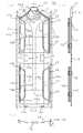
- the front view (a), the right side view (b), and the bottom view showing the mode in which the lower frame and the lower frame of the clothing storage device of the first embodiment are folded on the middle frame and the side frames.
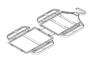
- FIG. 2 is a perspective view of a developed mode of the first embodiment.
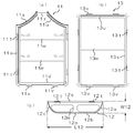
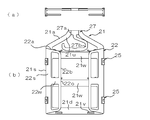
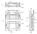
- FIG. 1 It is the top view (a) and front view (b) of the mode which the middle frame body and the side frame body of 2nd Embodiment folded. It is a front view of the whole developed mode of a 2nd embodiment.
- FIG. It is the top view (a), the front view (b), and the right side view (c) which show the folded aspect of 2nd Embodiment.
- the clothing storage device 10 of the present embodiment is connected to a middle frame 11 and left and right side portions of the middle frame 11 via a first connecting tool 15. And left and right side frame members 12 and a lower frame member 13 connected to a lower portion of the middle frame member 11 via a second connecting member 16.
- the middle frame 11 and the left and right side frames 12 connected via the first connecting member 15 correspond to the above-described upper frame in the present embodiment.
- the above-mentioned middle frame 11, side frame 12, and lower frame 13 (and lower frame 14 described later) are integrally formed of synthetic resin or the like.
- the first connector 15 and the second connector 16 (and a third connector 18 described later) are also integrally formed of synthetic resin or the like.
- each part is made of a material such as a hard resin having a certain degree of rigidity, but a flexible material such as rubber can be used as long as the support performance of the clothes CL can be secured. .
- the middle frame 11 is a frame (a frame that supports the clothes CL from the inside) having a rectangular planar shape as a whole.
- the sides of the left and right side portions 11s and the lower portion 11d are linear, while the sides of the upper portion 11u are formed in a mountain shape.
- a middle supporting upper edge 11a is formed on the left and right middle sides inside the upper part CLa of the garment CL.
- the middle supporting upper edge 11a has a shape that is wider in the front-rear direction than the other plate-like portions of the middle frame body 11, and gradually descends from the middle to the left and right in a concave curve shape. It has a form corresponding to the shoulder of a hanger with a contour that goes down.
- the middle support upper edge 11a is divided at the center, and the base 17a of the hook 17 is fitted to the divided portion so that the base 17a of the hook 17 has a horizontal axis shown in FIG. (See (a)).
- the locking portion 17b of the hook 17 is attached so as to be rotatable around an axis perpendicular to the base 17a. Further, an opening 17c is provided in the base 17a so that a tie or the like can be inserted and hung.
- a projection shaft 17d is formed at the lower end of the locking portion 17b, and this projection shaft 17d fits into a receiving hole 17e of a base 17a formed by overlapping the halves 17A and 17B.
- a pivoting support structure that is rotatable around a vertical axis of the locking portion 17b with respect to the base 17a is configured.
- a band-like horizontal portion 11 w connecting the left and right side portions 11 s.
- two horizontal portions 11w are formed vertically.
- the horizontal portion 11w is configured so that slacks or the like can be hung thereon.
- each frame means that the garment CL is supported from the inside, and there is no meaning related to other structures and shapes. Therefore, the term itself of each frame does not represent a specific structure or shape.
- the side frame 12 includes a linear inner portion 12 s on the side of the middle frame 11 and an arcuate outer portion 12 o on the opposite side to the middle frame 11.
- An upper portion of the outer portion 12o is provided with an outer support upper edge 12a extending obliquely downward and outward with a convex curve along an extension of the middle support upper edge 11a.
- the left and right inclined portions of the middle support upper edge 11a and the support surfaces of the outer support upper edges 12a of the left and right side frame bodies 12 are provided with a structure for preventing slip in a direction along the contour. For example, a surface uneven structure may be formed.
- An outer supporting side edge 12b extending linearly downward is provided at the center of the outer portion 12o.
- an outer support lower edge 12c is provided below the outer portion 12o and extends with a convex curved contour toward the inside obliquely downward.
- the outer support upper edge 12a and the outer support lower edge 12c are symmetrical, so that the overall shape of the outer portion 12o is also vertically symmetrical.
- the side frame 12 is provided with a horizontal portion 12w that connects an intermediate portion of the inner portion 12s and an intermediate portion of the outer portion 12o.
- the length L12 in the up-down direction is larger than the width W12 in the left-right direction.
- the length L12 is 1.5 times or more the width W12.
- the length L12 is twice or more (about 3.5 times) the width W12. This is for widening the vertical support range of the outer support side edge 12b.
- the left and right side portions CLb of the garment CL can be supported and guided by the outer support side edge 12b over a wide vertical support range. This is one of the features of the present embodiment in which a conventional hanger or hanger-type storage device is not provided.
- the center middle frame 11 and the left and right side frames 12, 12 are viewed in the left and right width directions, and are shown in a developed state shown in FIG. 1 (hereinafter, simply referred to as a "development state") and in FIG. They are connected by the first connecting member 15 so as to be in any of the folded modes (hereinafter, simply referred to as “folded modes”).
- the first connector 15 includes a middle frame-side connection portion 15a fitted to a connection shaft 11t having a vertical axis provided on the left and right side portions 11s of the middle frame body 11 shown in FIG.
- the distance between the middle frame side connection portion 15a and the side frame side connection portion 15b in the first connection portion 15, that is, the axis of the connection shaft 11t and the axis of the connection shaft 12t. Is the first interval G15.
- This first interval G15 is a value suitable for folding the left and right side portions CLb of the garment CL.
- the middle frame portion 11 and the side frame portion 12 each have two connection shafts 11t and 12t in the vertical direction, and are connected to each other by the first connection tool 15 at each of these portions.
- the connecting portion 15c of the first connecting member 15 is made of a flexible material such as a rubber material, the distance G15 may be slightly increased or decreased. This is the same for the second connector 16 and the third connector 18 described later.
- connection shafts 11t, 12t, the middle frame side connection portion 15a, and the side frame side connection portion 15b are fitted to each other and can be relatively rotated. Make up the structure.
- FIG. 4 shows only a connection structure (shaft support structure) between the connection shaft 11t and the middle frame side connection portion 15a, but a connection structure (shaft support structure) between the connection shaft 12t and the side frame side connection portion 15b. ) Is the same.
- the middle frame side connection portion 15a has a shaft support structure that rotatably supports the connection shaft 11t.
- the middle frame side connection portion 15a and the side frame side connection portion 15b are opposed to each other in the extending direction of the connecting portion 15c (the direction connecting the middle frame side connection portion 15a and the side frame side connection portion 15b).
- An opening that opens in the direction is provided, and through this opening, the middle frame side connection part 15a and the side frame side connection part 15b and the connection shafts 11t and 12t are configured to be detachable.
- the middle frame side connection portion 15a and the side frame side connection portion 15b and the connection shafts 11t and 12t are in a state of being rotatably fitted at the time of mounting.
- connection shafts 11t and 12t are fitted into the respective connection portions through the openings by the middle frame side connection portions 15a and the side frame side connection portions 15b being elastically deformed mainly in a manner to increase or decrease the opening width of the openings. (Snap-in) or withdrawal.
- connection structure shaft support structure
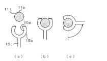
- a rib (convex streak) 11p is formed at a predetermined angular position on the outer peripheral surface of the connection shaft 11t, and the inside of the middle frame side connection portion 15a is formed.
- a concave groove 15g is formed at a corresponding angular position on the peripheral surface, and when the middle frame side connection portion 15a and the connecting shaft 11t have a predetermined angular relationship, the rib 11p and the concave groove 15g are fitted, and the angle The position is configured such that a predetermined holding force is generated around the axis.
- generates holding force between the side frame side connection part 15b and the connection shaft 12t is also the same.
- connection structure may be configured to generate a predetermined holding force at a predetermined angle.
- a holding force for holding an angle is generated between both connecting portions 15 a and 15 b of the first connecting tool 15 and the connecting shafts 11 t and 12 t.
- the first connecting member 15 is configured such that the connecting portion 15 c is substantially in the left-right direction (middle frame) between the middle frame 11 and the side frame 12.
- the posture is along the frame plane of the body 11).
- connection portions 15a and 15b may be configured to be smoothly rotatable with respect to the connection shafts 11t and 12t in the entire rotation range. This is the same in connection portions 16a, 16b and 18a, 18b described later.
- the upper portion 11u of the middle frame body 11 is configured to have a T-shaped cross section in which an outer portion bulges in the front-rear direction with respect to an inner portion configured in a plate shape, and as a result, has an upper edge portion formed to be wide. .
- the middle supporting upper edge 11a is configured as an upper surface of the upper edge portion.
- the middle supporting upper edge 11a is configured to have a surface shape that becomes a convex curved surface along the front-rear direction.
- the inner portion 12s of the side frame 12 is entirely formed in a plate shape, whereas the outer portion 12o arranged on the side opposite to the middle frame 11 in the unfolded state is a plate-shaped inner portion.
- the outer portion is configured to have a T-shaped cross section that bulges in the front-rear direction, and as a result, has a wide side edge.
- the outer supporting upper edge 12a, the outer supporting side edge 12b, and the outer supporting lower edge 12c are configured as outer surfaces of the side edge 12o.
- the outer support upper edge 12a, the outer support side edge 12b, and the outer support lower edge 12c are configured as mutually continuous surfaces from above to below.
- the outer support upper edge 12a may be shaped to protrude laterally beyond the outer support side edge 12b so that the outer support upper edge 12a can be inserted into the inside of the sleeve CLc from the shoulder opening of the garment CL like the left and right ends of the hanger. Good.
- the outer support side edge 12b is arranged inside the side part CLb below the shoulder opening of the sleeve part CLc of the garment CL. Accordingly, when the left and right side portions CLb of the garment CL are folded, the side portions CLb of the garment CL can be firmly guided from the inside, so that an orderly folding mode can be realized. Further, in the illustrated example, since the side frames 12 are formed symmetrically in the front-rear direction, the left and right side frames can be shared. In the illustrated example, the side frame 12 has a shape in which the outer support upper edge 12a and the outer support lower edge 12c do not protrude from the outer support side edge 12b, and thus is shared with the lower frame 14 described later. It becomes possible.
- the appearance of the clothing storage device 10 of the present embodiment is shown in a perspective view of FIG.
- the clothing storage device 10 of the present embodiment has symmetrical shapes on both front and back sides in the perspective view of FIG. Parts other than the hook 17 have symmetrical shapes and structures on both the left and right sides.
- connection shaft 11v having a horizontal axis is formed at a lower portion 11d of the middle frame 11.
- two connection shafts 11t are formed in the lower portion 11d.
- the connection shaft 11v is fitted to the middle frame side connection portion 16a of the second connection tool 16, and is rotatably connected.
- the second connecting member 16 includes the above-described middle frame side connection portion 16a, a lower frame side connection portion 16b connected to a lower frame body 13 described later, and the above described middle frame side connection portion.
- a connecting portion 16c for connecting the portion 16a and the lower frame side connecting portion 16b is provided.
- the distance between the middle frame side connection portion 16a and the lower frame side connection portion 16b in the second connection portion 16, that is, the distance between the axis of the connection shaft 11v and the axis of the connection shaft 13v is the second space G16. It has become.
- the second interval G16 is a value suitable for vertically folding the lower part CLd of the garment CL on the upper part CLa thereof in a manner in which the left and right side parts CLb of the garment CL are folded together with the side frame 12. Is done.
- the second interval G16 is larger than the first interval G15.
- the first interval G16 is preferably in the range of 1.6 to 2.4 times the first interval G15, and particularly preferably 2 times.
- the lower portion 11d of the middle frame portion 11 and the upper portion 13u of the lower frame portion 13 are provided with connecting shafts 11v and 13v at two locations in the left-right direction, respectively.
- the second connecting member 16 is different only in the length of the connecting portion 16c.
- the structure of the middle frame side connecting portion 16a and the lower frame side connecting portion 16b is the same as the connecting structure of the first connecting member 15 described above. It is formed in the same manner as the fitting structure, and the same applies to the structure for providing the above-mentioned holding force. In particular, in the deployed state shown in FIGS. 1 and 2, it is desirable that the holding force for holding the angular posture of the middle frame 11 and the lower frame 13 via the second connecting member 16 is generated.
- the lower frame 13 is a rectangular frame as a whole.
- each side of the upper portion 13u, the left and right side portions 13s, and the lower portion 13d is formed in a plate shape having a linear band-shaped planar shape.
- the lower part 13d may be formed in a mountain shape like the upper part 11u of the middle frame 11, and the hook 17 may be provided.
- a connection shaft 13v having a horizontal axis is provided on the upper portion 13u and the lower portion 13d.
- two connection shafts 13v are formed in each of the upper portion 13u and the lower portion 13d.
- the connection shaft 13v provided on the upper portion 13u is fitted to the lower frame side connection portion 16b of the second connection tool 16, and is rotatably connected.
- the lower frame body 13 has a symmetrical form on each of the front and back sides, the left and right sides, and the upper and lower sides.
- the lower frame 13 is connected to the lower frames 14 arranged on the left and right sides, respectively, via the third connecting member 18.
- the lower frame 13 and the left and right lower frames 14 connected via the third connector 18 correspond to the lower frame in the present embodiment.
- a connecting shaft 13t having a vertical axis is formed on each of the left and right side portions 13s, and the connecting shaft 13t is connected to the lower frame side connecting portion 18a of the third connecting member 18.
- the lower frame 14 includes a straight inner portion 14s and an arcuate outer portion 14o.
- a connection shaft 14t having a vertical axis is provided on the inner portion 14s, and the connection shaft 14t is rotatably connected by a lower frame side connection portion 18b of the third connection member 18.
- the outer portion 14o is provided with an outer support upper edge 14a, an outer support side edge 14b, and an outer support lower edge 14c similar to the side frame 12.
- the lower frame 14 has the same shape and structure as the side frame 12 completely.
- the lower frame 14 has a shape in which the outer support upper edge 14a and the outer support lower edge 14c do not protrude from the outer support side edge 14b, similarly to the side frame 12.
- the outer portion 14o (the outer support upper edge 14a, the outer support side edge 14b, and the outer support lower edge 14c) fits inside the side portion CLb of the garment CL.
- connection structure and the fitting structure of the third connector 18 are completely the same as those of the first connector 15, and the lower frame-side connection portion 18a, the lower frame-side connection portion 18b, and the connection portion are the same. 18c.
- the distance between the lower frame side connection portion 18a and the lower frame side connection portion 18b in the third connection portion 18, that is, the distance between the axis of the connection shaft 13t and the axis of the connection shaft 14t (the third G18) is configured the same as the first interval G15. Therefore, the second interval G16 is larger than the third interval G18.
- the entire width of the lower frame 13 in the left-right direction may be configured to be slightly different from the entire width of the middle frame 11 in the left-right direction (for example, to be slightly smaller).
- the lower frame portion may be constituted by only the lower frame member 13 to which the left and right lower frame members 14 are not connected.
- the clothing CL is hung on the upper portion 11 u of the middle frame 11 and the upper portion of the side frame 12 of the clothing storage device 10.
- the clothing CL (in the illustrated example, an outerwear, a coat, or the like) is hung on the clothing storage device 10 with its front facing rearward. That is, in FIG. 1, the back surface of the clothing CL is in a posture facing forward. However, the clothing CL may be hung on the clothing storage device 10 with the front of the clothing CL facing forward.
- the clothing storage device 10 In the state of FIG. 1, the clothing storage device 10 is in the unfolded state, and the middle support upper edge 11 a of the middle frame 11 and the outer support upper edge 12 a of the side frame 12 are arranged inside the upper CLa of the clothing CL, The clothes CL are supported from the inside. As a result, the clothes CL can be hung by the hooks 17.
- the outer supporting side edge 12b of the side frame 12 and the outer supporting side edge 14b of the lower frame 14 are arranged inside the side part CLb of the garment CL.
- the sleeve CLc is not directly supported from the inside. However, by projecting the outer support upper edge 12a of the side frame 12 outward from the outer support side edge 12b, the protruding portion is formed by the clothing CL.
- the lower part CLd of the garment CL is arranged at a position corresponding to the lower part 13d of the lower frame 13 in the illustrated example, but the positional relationship (up and down position) between the lower part CLd and the lower part 13d is arbitrary. Since the hook 17 is basically not used when being stored in a bag or a case, the hook 17 is rotated downward about the support shaft 11y as shown in FIG. (The inside of the middle frame 11).
- the left and right side portions CLb of the garment CL are folded forward to form a lateral folding mode.
- the side part CLb of the garment CL is folded onto the middle frame 11 together with the side frames 12 and the lower frame 14 arranged inside.
- the side CLb is connected to the side frame 12 and the lower side. While being guided from the inside by the side frame 14, it is orderly folded.
- the first connecting member 15 has an intermediate frame side connecting portion 15a and a side frame side connecting portion 15b, respectively, as shown in FIG. 2 (c). It rotates with respect to 11t and 12t, and each becomes a bent state.
- the side frame 12 and the lower frame 14 are different from the conventional structure in that the length L12 (L14) in the up-down direction is larger than the width W12 (W14) in the left-right direction, particularly 1.5 times or more, or 2 times.
- the outer support side edge 12b (14b) is raised and lowered while being dimensioned to accommodate the inner frame 11 and the side frame 12 (the lower frame 13 and the lower frame 14) inside the garment CL. It can be provided in a wide range of directions. Therefore, it is possible to fold the clothes CL orderly while the side parts CLb of the clothes CL are firmly guided from the inside. That is, it is possible to fold without breaking the fold by the guidance of the side frame 12 and the lower frame 14.
- the angle ⁇ shown in FIG. 2C (the frame plane of the middle frame body 11) relates to the first connector 15 and the third connector 18 that function to form the folding mode.
- the extending direction of the connecting portions 15b and 18b (the direction connecting the middle frame side connecting portion 15a, the lower frame side connecting portion 18a to the side frame side connecting portion 15b, and the lower frame side connecting portion 18b).
- the angle of intersection between them can be set to any angle in the range from 90 degrees to another angle smaller than 90 degrees.
- the angle ⁇ is movable within a range of at least 20 to 160 degrees.
- the interval between the directions in which the middle frame 11 and the side frame 12 (or the lower frame 13 and the lower frame 14) face each other is as described above.
- the first interval G15 (the third interval G18) is the maximum.
- the angle ⁇ is smaller than 90 degrees, the interval in the facing direction becomes smaller than the first interval G15 (the third interval G18) due to the inclination of the connecting portion 15c (18c).
- the thickness of the structure is also reduced.
- the side frame body 12 (lower frame body 14) is disposed outward with respect to the middle frame body 11 (lower frame body 13) by an amount corresponding to the inclination of the connecting portion 15c (18c).
- the angle ⁇ is slightly increased in the left-right direction.
- the gap in the facing direction is smaller than the first gap G15 (third gap G18), and the thickness of the folded structure is also reduced. I do.
- the side frame 12 (lower frame 14) is arranged inward with respect to the middle frame 11 (lower frame 13) by an amount corresponding to the inclination of the connecting portion 15c (18c).
- the space in the left-right direction of the portion to be arranged is slightly reduced.
- the angle ⁇ is changed according to the thickness of the cloth of the clothing CL or the size of each part of the clothing CL, and the like, so that the clothing storage device 10 and the entire clothing CL are changed.
- the thickness and width in the left-right direction can be adjusted. For example, it is possible to make the overall dimensions (thickness in the front-rear direction and width in the left-right direction) as compact as possible in accordance with the clothes CL.
- the angle between the installation plane of the side frame 12 and the extending direction of the connecting portions 15c and 18c is 0 degree in the unfolded state shown in FIG. 1 and the horizontal folding shown in FIG.
- the angle value is around 90 degrees at least close to 90 degrees.
- the angle range in which the connection angle can be changed must be a range including at least the above-mentioned 0 degree to a value around 90 degrees.
- connection angle ranges of the connection angles in the connection portions 15a, 18a, 15b, 18b are as follows: the middle frame 11 or the lower frame 13, the side frame 12, or the lower frame in the folding mode.
- the connection angle can be variably set within a range of 0 to 180 degrees by not causing interference between the connection portions 14 or 14 and the connection portions 15c and 18c. It is.
- the interference can be avoided by reducing the thickness, increasing the interval, and reducing the width in the inward and outward directions of the adjacent regions of the members other than the connection portions 15a, 15b, 18a, and 18b. For example, in the deployment mode shown in FIG.
- the inner edge of the side portion 11 s of the middle frame 11 is formed as shown by a dotted line to reduce the width of the side 11 s in the inward and outward directions, and the inner portion 12 s of the side frame 12.
- the inner frame body 11 and the inner frame body 11 are formed by a method of reducing the width of the inner edge and removing the corners, or a method of reducing the thickness of the side portion 11 s and the inner portion 12 s. Interference in the thickness direction of the frame 12 can be avoided.
- the lower part CLd of the garment CL is folded upward to form a vertical folding mode.
- the lower CLd is folded onto the middle frame 11 and the side frame 12 together with the lower frame 13 and the lower frame 14 arranged inside.
- the overall thickness of the clothing CL and the clothing storage device 10 is increased, but the second interval G16 of the second coupling tool 16 is larger than the first interval G15 (third interval G18) ( Preferably, it is 1.6 to 2.4 times, particularly 2 times, so that it can be folded without any trouble.
- the first connector 15, the second connector 16, and the third connector 18 are shared, and the first interval G15, the second interval G16, the third May be set to the same value.
- the angle ⁇ is relatively largely shifted before and after 90 degrees, and the extending direction of the connecting portions 15c and 18c is folded.
- the inner frame 11 and the side frame 12, or the lower frame 13 and the lower frame 14 are configured to be inclined from the direction in which they face each other, and viewed in the facing direction.
- the substantial interval is made smaller than G15 or G18, and in the second connecting member 16, the angle ⁇ is set relatively to 90 degrees or close to 90 degrees, and the inclination of the extending direction with respect to the facing direction is eliminated.
- the angle ⁇ shown in FIG. 3B (the direction along the frame plane of the middle frame body 11 and the extending direction of the connecting portion 16b (the middle frame side connection portion 16a and the lower frame side connection
- the angle of intersection with the direction connecting the portions 16b) can be set to any angle in the range from an angle larger than 90 degrees to another angle smaller than 90 degrees. ing.
- the angle ⁇ is 90 degrees
- the interval in the direction in which the middle frame 11 and the lower frame 13 face each other is the second interval G16, which is the maximum.
- the angle ⁇ is smaller than 90 degrees, the interval in the facing direction is smaller than the second interval G16, so that the thickness of the folded structure also decreases.
- the lower frame 13 is disposed below the middle frame 11 by an amount corresponding to the inclination of the connecting portion 16c, the vertical arrangement space of the portion on the lower side of the clothing CL is small. Increase. Further, when the angle ⁇ is larger than 90 degrees, the interval in the facing direction is smaller than the second interval G16, so that the thickness of the folded structure is also reduced. On the other hand, since the lower frame 13 is disposed above the middle frame 11 by an amount corresponding to the inclination of the connecting portion 16c, the space in the vertical direction of the lower portion of the garment CL is reduced although it is small. I do.
- the angle ⁇ is changed according to the thickness of the cloth of the clothing CL or the size of each part of the clothing CL, and the like, so that the clothing storage device 10 and the entire clothing CL are changed.
- the thickness and length in the vertical direction can be adjusted. For example, it is possible to make the overall dimensions (the thickness in the front-rear direction and the length in the vertical direction) as compact as possible in accordance with the clothing CL.
- the respective connection angles of the connection portions 16 a and 16 b provided on both sides of the connection portion 16 c (the installation plane of the middle frame 11 or the lower frame 13 and the connection 16c is 0 degree in the unfolded state shown in FIGS. 1 and 2, and is at least close to 90 degrees in the longitudinally folded state shown in FIG. Angle values before and after degrees.
- the angle range in which the connection angle can be changed must be a range including at least the above-mentioned 0 degree to a value around 90 degrees.
- the changeable angle range of the connection angle in each of the connection portions 16a and 16b is determined between the middle frame 11 and the side frame 12 and the lower frame 13 and the lower frame 14 in the vertical folding mode.
- connection angle can be variably set in the range of 0 to 180 degrees by preventing the interference between them or the connection portion 16c from occurring.
- the interference can be avoided by reducing the thickness, increasing the interval, and reducing the width in the inward and outward directions of the region adjacent to each member other than the connection portions 16a and 16b. For example, the vertical width and the thickness of the lower portion 11d of the middle frame 11 shown in FIG. 1 are reduced and the vertical width and the thickness of the upper portion 13u of the lower frame 13 are reduced.
- the middle frame 21 (upper portion 21u, side portion 21s, lower portion 21d, middle support upper edge 21a, connecting shafts 21t, 21v, horizontal portion 21w), side frame 22 (inner portion 22s, outer portion).
- each frame is different from the first embodiment in that it does not have a thick upper edge shape or an outer edge shape bulging in the front-rear direction, and is formed in a plate shape as a whole.
- the first connector 25, the second connector 26, and the third connector 28 are connected to each of the connecting portions (the middle frame side connecting portion 25a, the side frame side connecting portion 25b, the middle frame side connecting portion 26a, Each opening of the frame-side connection portion 26b, the lower frame-side connection portion 28a, and the lower frame-side connection portion 28b) opens in a direction along the extending direction of the connection portion as in the first embodiment. In contrast to this, the opening is opened in a direction orthogonal to the extending direction of the connecting portions 25c, 26c, 28c.
- the third connector 28 has the same shape and structure as the first connector 25.
- the clothing CL can be folded vertically and horizontally with the clothing CL attached.
- the angle ⁇ and ⁇ by changing the angle ⁇ and ⁇ , the overall thickness and size can be adjusted, and the overall dimensions at the time of storage can be made compact according to the clothing CL. The same is true.
- the entirety in the folded state is stored in a bag, case, or bag (not shown) so that the clothing CL can be easily stored and carried. Can be.
- the specific size is not particularly limited, but, for example, it is possible to put almost all the clothes CL in a plane shape of A3 size.
- the clothes CL can be returned to the original form by a simple operation, and the clothes storage devices 10 and 20 disposed inside can be suspended as they are.
- the clothing storage device of the present invention is not limited to the illustrated example described above, and it goes without saying that various changes can be made without departing from the spirit of the present invention.
- the middle support upper edges 11a, 21a are provided on the upper portions 11u, 21u of the middle frame members 11, 21, and the outer support upper edges 12a are provided on the outer portions 12o, 22o of the side frame members 12, 22.
- the clothes storage device according to the present invention is arranged such that the inner supporting upper edges 11a, 21a and the outer supporting It merely shows that the edges 12a, 22a are used and that the outer support side edges 12b, 22b are used inside the side part CLb of the garment CL. Therefore, according to the present invention, the middle supporting upper edges 11a and 21a, the outer supporting upper edges 12a and 22a, and the outer supporting side edges 12b and 22b have a form having a thickness in the front-rear direction as shown in the drawing. It is not required that the middle frame bodies 11 and 21 have the shape of a chevron as shown in the figure.
- the middle frame bodies 11 and 21 may be flat upper portions 13 u such as the lower frame bodies 13 and 23. 23u may be provided.
- each of the connecting members 15, 25, 16, 26, 18, and 28 includes a connecting shaft 11t, 21t, 12t, 22t, 13t, 23t, 14t, which is formed on the side of each frame.
- Each of the connecting portions 15a, 15b, 16a, 16b, 18a, and 18b rotatably supports the 24t, 11v, 21v, 13v, and 23v.
- a shaft supporting portion is provided on each frame. It may be formed so that a connecting shaft is formed at a connecting portion of each connecting tool.
- connection portions 15a, 15b, 16a, 16b, 18a, and 18b are rotatably connected to the frames 11, 12, 13, and 14, respectively.
- Each connection part may be connected to each frame in a manner that allows a connection angle to be changed. Therefore, for example, each of the connection portions may be a bendable bending portion.
- the clothing storage devices 10 and 20 are not limited to outerwear (clothes) as shown in the figure, but also include shirts, coats, kimonos (furisode, yukata, etc.), underwear, work clothes, swimwear, pajamas, gowns, robes, dresses, and the like. It can also be used for various types of clothing. Further, it may be used for other clothes such as pants, skirts, tights, and scarves. For example, pants (trousers) are hung on the horizontal portions 11w and 21w, and the legs of the pants are further lowered with the horizontal portions 11w and 21w, the lower portions 11d and 21d, and the horizontal portions 13w and 23w or the lower portions 13d and 23d. By passing in between, it can be held alone or inside other outfits such as jacket jackets.
- the middle frame 11, the side frame 12, the lower frame 13, the lower frame 14, or the upper frame and the lower frame are each configured in a frame shape capable of supporting clothing from the inside as a whole. What is necessary is just a thing,
- the planar shape and thickness distribution, or the inside structure of the said horizontal part 11w, 21w, 12w, 22w, etc. are not limited.
Landscapes
- Holders For Apparel And Elements Relating To Apparel (AREA)
Abstract
L'objectif de la présente invention est de fournir un accessoire de réception des vêtements, lequel permet de plier correctement les vêtements en fonction d'un mode du vêtement auquel l'accessoire de réception des vêtements doit être appliqué, ce qui permet à des vêtements d'être reçus de manière compacte tout en supprimant un désordre dans le mode de pliage desdits vêtements. Un accessoire de réception des vêtements (10) est pourvu d'un corps de cadre (11à central et des corps de cadre (13) latéraux reliés respectivement au corps de cadre central au moyen des premiers accessoires de raccordement (15) de telle sorte que lesdits corps de cadre latéraux peuvent être ouverts et pliés. Les premiers accessoires de liaison (15) comprennent respectivement : une partie de raccordement (15a) côté cadre central raccordée au corps de cadre central de telle sorte qu'un angle de raccordement dudit corps de cadre central peut être modifié ; une partie de raccordement (15b) côté cadre latéral raccordée au corps de cadre latéral de telle sorte qu'un angle de raccordement dudit corps de cadre latéral peut être modifié ; et une partie de raccordement (15c), laquelle relie la partie de raccordement côté cadre central et la partie de raccordement côté cadre latéral avec un premier espace (G15) entre lesdites parties de raccordement.
Applications Claiming Priority (2)
| Application Number | Priority Date | Filing Date | Title |
|---|---|---|---|
| JP2018123843A JP7033312B2 (ja) | 2018-06-29 | 2018-06-29 | 衣類収納具 |
| JP2018-123843 | 2018-06-29 |
Publications (1)
| Publication Number | Publication Date |
|---|---|
| WO2020003786A1 true WO2020003786A1 (fr) | 2020-01-02 |
Family
ID=68986323
Family Applications (1)
| Application Number | Title | Priority Date | Filing Date |
|---|---|---|---|
| PCT/JP2019/019367 Ceased WO2020003786A1 (fr) | 2018-06-29 | 2019-05-15 | Accessoire de réception des vêtements |
Country Status (2)
| Country | Link |
|---|---|
| JP (1) | JP7033312B2 (fr) |
| WO (1) | WO2020003786A1 (fr) |
Citations (8)
| Publication number | Priority date | Publication date | Assignee | Title |
|---|---|---|---|---|
| JPS3721651Y1 (fr) * | 1961-04-14 | 1962-08-20 | ||
| JPS5072428U (fr) * | 1973-11-10 | 1975-06-25 | ||
| JPS57145351U (fr) * | 1981-03-10 | 1982-09-13 | ||
| JPS59127536U (ja) * | 1983-02-17 | 1984-08-28 | ソ−コ−株式会社 | ハンガ− |
| JPH0364077U (fr) * | 1989-10-25 | 1991-06-21 | ||
| JP2004344445A (ja) * | 2003-05-23 | 2004-12-09 | Yoji Ichikawa | 整形ハンガー |
| JP3215493U (ja) * | 2015-04-08 | 2018-03-29 | ソン,ジュヒョン | 半折り畳み式ハンガー |
| JP2018068994A (ja) * | 2016-10-26 | 2018-05-10 | 野田 佳孝 | 折りたたみ式ハンガー |
-
2018
- 2018-06-29 JP JP2018123843A patent/JP7033312B2/ja not_active Expired - Fee Related
-
2019
- 2019-05-15 WO PCT/JP2019/019367 patent/WO2020003786A1/fr not_active Ceased
Patent Citations (8)
| Publication number | Priority date | Publication date | Assignee | Title |
|---|---|---|---|---|
| JPS3721651Y1 (fr) * | 1961-04-14 | 1962-08-20 | ||
| JPS5072428U (fr) * | 1973-11-10 | 1975-06-25 | ||
| JPS57145351U (fr) * | 1981-03-10 | 1982-09-13 | ||
| JPS59127536U (ja) * | 1983-02-17 | 1984-08-28 | ソ−コ−株式会社 | ハンガ− |
| JPH0364077U (fr) * | 1989-10-25 | 1991-06-21 | ||
| JP2004344445A (ja) * | 2003-05-23 | 2004-12-09 | Yoji Ichikawa | 整形ハンガー |
| JP3215493U (ja) * | 2015-04-08 | 2018-03-29 | ソン,ジュヒョン | 半折り畳み式ハンガー |
| JP2018068994A (ja) * | 2016-10-26 | 2018-05-10 | 野田 佳孝 | 折りたたみ式ハンガー |
Also Published As
| Publication number | Publication date |
|---|---|
| JP7033312B2 (ja) | 2022-03-10 |
| JP2020000566A (ja) | 2020-01-09 |
Similar Documents
| Publication | Publication Date | Title |
|---|---|---|
| JP2022506574A (ja) | 衣類ハンガー | |
| WO2020003786A1 (fr) | Accessoire de réception des vêtements | |
| CN112423629A (zh) | 衣架 | |
| JP3130529U (ja) | 買い物袋 | |
| KR200486867Y1 (ko) | 옷걸이 | |
| JP5095866B1 (ja) | 上着用保形具 | |
| JP6055207B2 (ja) | 上衣 | |
| JP3241809U (ja) | 衣類折り畳み用補助具 | |
| KR102010868B1 (ko) | 의류걸이 세트 | |
| JP6655208B1 (ja) | 衣服用ハンガー | |
| JP3014241U (ja) | シャツ類の折り畳み用ハンガー | |
| JP2021194275A (ja) | 収容構造及び収容構造用シート | |
| KR102643450B1 (ko) | 옷걸이 | |
| JP6934216B1 (ja) | マスクハンガー | |
| GB2118526A (en) | Foldable protective bag for clothing | |
| JPH0350794Y2 (fr) | ||
| KR102442551B1 (ko) | 옷걸이 | |
| JP4627867B2 (ja) | パターンシーマー用パターンパット | |
| JP2006102484A (ja) | 着物用ハンガー | |
| JP3054051U (ja) | 鞄内蔵用プレートハンガー | |
| KR200188517Y1 (ko) | 벽면부착용 절첩식 옷걸이. | |
| JP2017179662A (ja) | 股下寸法調整可能なズボン | |
| JP2023178629A (ja) | 衣服裾部分の持ち上げ支持具の連繋部材及び衣服裾部分の持ち上げ支持具 | |
| KR20220000615U (ko) | 연결식 옷걸이 | |
| KR101686334B1 (ko) | 바구니 수납형 세탁물 건조대 |
Legal Events
| Date | Code | Title | Description |
|---|---|---|---|
| 121 | Ep: the epo has been informed by wipo that ep was designated in this application |
Ref document number: 19825758 Country of ref document: EP Kind code of ref document: A1 |
|
| NENP | Non-entry into the national phase |
Ref country code: DE |
|
| 122 | Ep: pct application non-entry in european phase |
Ref document number: 19825758 Country of ref document: EP Kind code of ref document: A1 |