WO2020003839A1 - 制御装置、制御装置の制御方法、情報処理プログラム、および記録媒体 - Google Patents
制御装置、制御装置の制御方法、情報処理プログラム、および記録媒体 Download PDFInfo
- Publication number
- WO2020003839A1 WO2020003839A1 PCT/JP2019/020770 JP2019020770W WO2020003839A1 WO 2020003839 A1 WO2020003839 A1 WO 2020003839A1 JP 2019020770 W JP2019020770 W JP 2019020770W WO 2020003839 A1 WO2020003839 A1 WO 2020003839A1
- Authority
- WO
- WIPO (PCT)
- Prior art keywords
- spindle
- future
- slave
- axis
- control
- Prior art date
- Legal status (The legal status is an assumption and is not a legal conclusion. Google has not performed a legal analysis and makes no representation as to the accuracy of the status listed.)
- Ceased
Links
Images


Classifications
-
- G—PHYSICS
- G05—CONTROLLING; REGULATING
- G05D—SYSTEMS FOR CONTROLLING OR REGULATING NON-ELECTRIC VARIABLES
- G05D3/00—Control of position or direction
- G05D3/12—Control of position or direction using feedback
-
- H—ELECTRICITY
- H02—GENERATION; CONVERSION OR DISTRIBUTION OF ELECTRIC POWER
- H02P—CONTROL OR REGULATION OF ELECTRIC MOTORS, ELECTRIC GENERATORS OR DYNAMO-ELECTRIC CONVERTERS; CONTROLLING TRANSFORMERS, REACTORS OR CHOKE COILS
- H02P5/00—Arrangements specially adapted for regulating or controlling the speed or torque of two or more electric motors
- H02P5/46—Arrangements specially adapted for regulating or controlling the speed or torque of two or more electric motors for speed regulation of two or more dynamo-electric motors in relation to one another
Definitions
- the present invention relates to a control device and the like for causing the position of the slave shaft to follow the position of the master shaft.
- Patent Document 1 listed below discloses a synchronous control device that drives a slave shaft motor in synchronization with a spindle motor, and uses a dynamic characteristic model of the spindle device to predict a future spindle position increment value. Is disclosed.
- JP-A-9-289788 (published November 4, 1997)
- One aspect of the present invention is to improve the followability of the slave axis control with respect to the spindle position.For example, in order to sufficiently exhibit the performance of model predictive control applied to the slave axis control, a future feedback value of the spindle is adjusted. It is intended to predict and predict the future command value of the corresponding slave axis.
- a control device is a control device that causes a position of a slave shaft to follow a position of a main shaft, and (A) feedback-controls the position of the main shaft. Assuming that the current acceleration of the spindle feedback position, which is the feedback position of the spindle, of the first servo control system continues to be constant for a predetermined period, or (B) a command generated from the target trajectory of the spindle.
- a prediction unit that predicts the future spindle feedback position in the future, assuming that the current time change rate of the position deviation that is the deviation between the spindle command position that is the position and the spindle feedback position continues to be constant for a predetermined period.
- a calculation unit that calculates a dependent position, and a predicted position of the slave shaft in the future, which is predicted using a dynamic characteristic model of a second servo control system that feedback-controls the position of the slave shaft, is calculated by the calculation unit.
- a slave axis command unit that generates a slave axis command value that is a current command value for the second servo control system so as to match the corresponding dependent position.
- a control method is a control method for a control device that causes a position of a slave shaft to follow a position of a main shaft, and (A) controlling a position of the main shaft. Assuming that the current acceleration of the spindle feedback position, which is the feedback position of the spindle, of the first servo control system that performs feedback control continues to be constant for a predetermined period, or (B) generated from the target trajectory of the spindle.
- the spindle feedback position in the future is predicted.
- Prediction step corresponding to the spindle feedback position in the future predicted in the prediction step, A calculating step of calculating a corresponding subordinate position that is a position of the subordinate axis; and a predicted position of the subordinate axis in the future, which is predicted using a dynamic characteristic model of a second servo control system that feedback-controls the position of the subordinate axis.
- a slave axis command step of generating a slave axis command value that is a current command value for the second servo control system so as to match the corresponding dependent position calculated in the calculation step.
- FIG. 2 is a block diagram illustrating a main configuration of a controller and the like according to the first embodiment of the present invention.
- FIG. 2 is a flowchart illustrating an outline of a process executed by a controller in FIG. 1.
- FIG. 9 is a block diagram illustrating a main configuration of a controller and the like according to a second embodiment of the present invention.
- FIG. 4 is a flowchart illustrating an outline of a process executed by a controller in FIG. 3.
- FIG. 11 is a block diagram illustrating a main configuration of a controller and the like according to a third embodiment of the present invention.
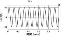
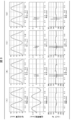
- FIG. 4 is a diagram illustrating a disturbance applied to control of a spindle in a simulation 1; FIG.
- FIG. 7 is a diagram illustrating slave axis control realized by the conventional controller and the controller according to each embodiment when the disturbance shown in FIG. 6 is applied.
- FIG. 9 is a diagram illustrating a disturbance applied to control of a spindle in a simulation 2;
- FIG. 9 is a diagram illustrating slave axis control realized by the conventional controller and the controller according to each embodiment when the disturbance shown in FIG. 8 is applied.
- each of the controllers 100, 500, and 900 for controlling a control target such as a machine and equipment will be described as a typical example of a control device.
- Each of the controllers 100, 500, and 900 is, for example, a PLC (Programmable Logic Controller).
- PLC Programmable Logic Controller
- the controller 100 is a control device that executes control for causing the position of the slave shaft to follow the position of the main shaft.
- the controller 100 applies model predictive control (hereinafter, abbreviated as “MPC”) to the control of the slave axis to improve the followability of the control of the slave axis.
- MPC model predictive control
- the controller 100 predicts a future feedback (Feed Back, hereinafter abbreviated as “FB”) value of the spindle, and calculates a future command value of the slave axis corresponding to the predicted future FB value of the spindle. That is, the future command value of the slave axis is predicted from the predicted future FB value of the master axis. Then, the controller 100 sufficiently improves the followability of the control of the slave axis by applying the MPC using the predicted “future command value of the slave axis” to the control of the slave axis.
- FB Future feedback
- the controller 100 improves the followability of the slave axis with respect to the master axis, so that the operation of machines controlled by the controller 100 can be further speeded up, and contributes to an improvement in productivity at a production site using these machines. be able to.
- the controller 100 is applied to electronic cam control.
- the application example of the controller 100 is not limited to the electronic cam control, but may be any "control that causes the position of the slave shaft to follow the position of the main shaft".
- the details of the controller 100 will be described with reference to FIGS. 1 and 2.
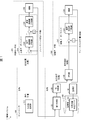
- FIG. 1 is a block diagram illustrating a main configuration of the controller 100 and the like. Hereinafter, in order to facilitate understanding of the controller 100, first, an outline of the control system 1 including the controller 100 will be described.
- the control system 1 illustrated in FIG. 1 includes a controller 100, which is a higher-level controller, and a main axis servo system 200 and a sub axis servo system 300 controlled by the controller 100.
- the spindle servo system 200 is a feedback control system including a spindle servo driver 210 and a machine 240 (for example, a motor and a mechanism) whose driving is controlled by the spindle servo driver 210.
- the slave axis servo system 300 is a feedback control system including a slave axis servo driver 310 and a machine 330 (for example, a motor and a mechanism) whose driving is controlled by the slave axis servo driver 310.
- the controller 100 and each of the master axis servo driver 210 and the slave axis servo driver 310 are communicably connected, and the connection method is an arbitrary wired connection method or a wireless connection method.
- the spindle servo driver 210 controls the output (that is, the position of the spindle) of the machine 240 in accordance with the "command value for the spindle" received from the controller 100 every predetermined control cycle (spindle-side control cycle). Feedback control device.
- the output of the machine 240 is input to each of the spindle servo driver 210 and the controller 100 as an FB value of the spindle position (hereinafter, also referred to as “FB position (spindle)”).
- the spindle servo driver 210 uses the “command value (eg, command position (spindle)) for the spindle” from the controller 100 as a target value, and sends the measured value (eg, FB position (spindle)) as a feedback value to the machine 240. Perform feedback control. That is, the spindle servo driver 210 adjusts the current for driving the machine 240 (particularly, a servomotor included in the machine 240) such that the measured value approaches the target value.
- the spindle servo driver 210 may be called a servo motor amplifier.
- the spindle servo driver 210 in FIG. 1 includes a position control unit 220 that performs proportional control (P control) and a speed control unit 230 that performs proportional integration control (PI control).
- P control proportional control
- PI control proportional integration control
- command position (spindle) is also received.
- the position control unit 220 outputs a command speed from a position deviation which is a deviation between a command position (spindle) received from the controller 100 and an FB position (spindle) acquired by an encoder or the like.
- the speed control unit 230 calculates a command torque (spindle) from a speed deviation (spindle) which is a deviation between the command speed output from the position control unit 220 and the FB speed (spindle) calculated by differentiating the FB position (spindle).
- a command torque spindle
- spindle speed deviation
- spindle speed deviation
- spindle speed deviation
- the slave axis servo driver 310 outputs the output of the machine 330 (that is, the slave axis) in accordance with the "command value for the slave axis" received from the controller 100 every predetermined control cycle (slave axis side control cycle). Is a feedback control device for controlling the position of the feedback control.
- the output of the machine 330 is input to each of the slave axis servo driver 310 and the controller 100 as the FB value of the slave axis position (hereinafter, also referred to as “FB position (slave axis)”).
- the slave axis servo driver 310 uses the “command value for the slave axis (eg, command speed (slave axis))” from the controller 100 as the target value, and calculates the actual measurement value (eg, FB obtained by time-differentiating the FB position (slave axis)). Using the speed (slave axis) as a feedback value, feedback control is performed on the machine 330. That is, the slave axis servo driver 310 adjusts the current for driving the machine 330 (in particular, the servomotor included in the machine 330) so that the measured value approaches the target value. Note that the slave axis servo driver 310 may be referred to as a servo motor amplifier.
- the slave axis servo driver 310 in FIG. 1 includes a speed control unit 320 that performs proportional-integral control (PI control), and the controller 100 issues a command speed for the slave axis (hereinafter, also referred to as a “command speed (slave axis)”). Is received.
- the speed control unit 320 is a speed deviation (deviation) between a command speed (slave axis) received from the controller 100 and an FB speed (slave axis) calculated by differentiating an FB position (slave axis) acquired by an encoder or the like. From the slave axis), a command torque (slave axis) is generated.
- the slave axis servo driver 310 controls the machine 330 based on the generated command torque (slave axis).
- the controller 100 controls the entire control system 1 including the master axis servo system 200 and the slave axis servo system 300, and is, for example, a programmable controller (PLC, Programmable Logic Controller).
- PLC Programmable Logic Controller
- the controller 100 outputs a command value to each of the master axis servo system 200 and the slave axis servo system 300 to control each of the master axis servo system 200 and the slave axis servo system 300.
- the controller 100 controls the spindle servo system 200 by, for example, outputting a “command position (spindle)”, which is a command position for the spindle, to the spindle servo system 200 in each spindle-side control cycle.
- the controller 100 controls the slave axis servo system 300 by, for example, outputting a “command speed (slave axis)”, which is a command speed for the slave axis, to the slave axis servo system 300 in each slave axis side control cycle. I do.
- the controller 100 applies MPC using the dynamic characteristic model of the slave axis servo system 300 to control the slave axis servo system 300.
- the control cycle (spindle-side control cycle) of the controller 100 for the spindle servo system 200 and the control cycle (slave-axis control cycle) of the controller 100 for the slave axis servo system 300 may be the same or may be the same time. It is not necessary.
- the slave axis side control cycle may be shorter than the master axis side control cycle, that is, the slave axis side control cycle may be faster than the master axis side control cycle.
- the length (time interval) of the master-side control cycle is desirably an integral multiple of the length (time interval) of the slave-axis control cycle. In the following description, an example will be described in which the main axis control cycle and the slave axis control cycle have the same time interval.
- the controller 100 acquires the FB value from the master axis servo system 200 and the slave axis servo system 300 and uses the FB value for controlling the master axis servo system 200 and the slave axis servo system 300.
- the controller 100 acquires, for example, the FB position (spindle), which is the output of the machine 240 (ie, the position of the spindle), from the spindle servo system 200 and uses the FB position for controlling the spindle servo system 200 and the slave axis servo system 300.
- the controller 100 acquires, for example, an FB position (slave axis), which is the output of the machine 330 (ie, the position of the slave axis), from the slave axis servo system 300 and uses the FB position to control the slave axis servo system 300.
- an FB position slave axis
- the controller 100 acquires, for example, an FB position (slave axis), which is the output of the machine 330 (ie, the position of the slave axis), from the slave axis servo system 300 and uses the FB position to control the slave axis servo system 300.
- the controller 100 applies MPC using the dynamic characteristic model of the slave axis servo system 300 to control the slave axis servo system 300. Specifically, the controller 100 sets the current command so that the future FB position (slave axis) predicted using the dynamic characteristic model of the slave axis servo system 300 matches the “future command value of the slave axis”. Generate velocity (slave axis). In particular, the controller 100 predicts the FB position (spindle) in the future control cycle from the FB position (spindle) in each of the current control cycle and the past control cycle.
- the controller 100 predicts a future FB value of the spindle using only the past and present FB values of the spindle.
- the controller 100 uses the FB position (spindle) of the main axis in the current and past cycles, assuming that the acceleration of the FB position (spindle) of the current cycle is constant and continues, and assumes the FB position (future cycle) of the future cycle. Main axis).
- the controller 100 sets the future command value of the slave axis (that is, the command position (the slave axis) in the future cycle) corresponding to the predicted future FB value of the spindle (that is, the FB position (spindle) in the future cycle).
- the MPC is executed for the slave axis servo system 300.
- the controller 100 is a control device that causes the position of the slave shaft to follow the position of the main shaft, and includes a first prediction unit 120 (prediction unit), a cam calculation unit 130 (calculation unit), and an MPC. Unit 140 (slave axis command unit).
- the first prediction unit 120 determines that the current acceleration of the FB position (spindle), which is the feedback position of the spindle, of the spindle servo system 200 (first servo control system) that performs feedback control of the position of the spindle is constant over a predetermined period.
- FB position main axis
- the cam calculation unit 130 calculates a corresponding subordinate position that is a “position of the slave axis” corresponding to the “FB position (main axis) in the future” predicted by the first prediction unit 120.
- the MPC unit 140 calculates the “predicted position of the slave shaft in the future” predicted by using the dynamic characteristic model of the slave servo system 300 (second servo control system) that performs feedback control of the position of the slave shaft.
- a slave axis command value that is a current command value for the slave axis servo system 300 is generated so as to match the calculated “corresponding dependent position in the future”.
- the controller 100 predicts the FB position (main axis) in the future on the assumption that the current acceleration of the FB position (main axis) remains constant for a predetermined period. For example, the controller 100 predicts the future FB position (main axis) assuming that the “current FB acceleration (main axis)” calculated from the “current FB position (main axis)” will remain constant over a predetermined period. I do.
- the controller 100 determines the future position of the slave axis corresponding to the future FB position (main axis) from the future FB position (main axis) predicted without using the dynamic characteristic model of the main axis servo system 200. Calculate the position. Then, the controller 100 converts the MPC using the dynamic characteristic model of the slave axis servo system 300, in which the calculated corresponding slave position (position of the future slave axis) is used as the future command value (command position) of the slave axis. Applies to axis control.
- the controller 100 predicts the FB position (spindle) in the future, and sets the “corresponding subordinate position (future command value of the slave axis, command position in the future cycle) corresponding to the predicted“ FB position (spindle) in the future ”. (Slave)) is applied to the control of the slave.
- the controller 100 has an effect that the followability of the position control of the slave shaft is improved, and the speed and accuracy of the position control of the slave shaft can be increased.
- the controller 100 has the effect of increasing the speed of operations of machines and the like controlled by the controller 100 and contributing to an improvement in productivity at a production site using these machines.
- the controller 100 causes the position of the slave shaft to follow the position of the main shaft, for example.
- the first prediction unit 120 assumes that "the acceleration of the FB position (spindle axis) in each cycle (each spindle-side control cycle) is constant over a plurality of cycles (spindle-side control cycle)."
- the FB position (spindle) in a future cycle (spindle-side control cycle) is predicted using the FB position (spindle) in each of the current and past cycles (each spindle-side control cycle).
- the controller 100 uses the FB position (spindle) in each of the current and past cycles (each spindle-side control cycle) to determine the FB position (spindle) in the future cycle (spindle-side control cycle). Predict.
- the controller 100 calculates the difference between the FB position (spindle) in the current cycle (spindle-side control cycle) and the FB position (spindle-side control cycle) one cycle before the current cycle (spindle-side control cycle) in the cycle (spindle-axis).
- the feedback speed (FB speed (spindle)) of the spindle servo system 200 in the current cycle (spindle-side control cycle) is calculated by dividing by the cycle time that is the time interval of the side control cycle.
- the controller 100 divides the difference between the FB position (spindle) in the cycle one cycle before the current cycle and the FB position (spindle) in the cycle two cycles before the current cycle by the cycle time to determine the difference from the current cycle time.
- the FB speed (main axis) in the cycle one cycle before is calculated.
- the controller 100 divides the difference between the FB speed (spindle) in the current cycle and the FB speed (spindle) in the cycle immediately before the current cycle by the cycle time to obtain the spindle servo system in the current cycle.
- a feedback acceleration (FB acceleration (main axis)) of 200 is calculated.
- the controller 100 assumes that the calculated “FB acceleration (principal axis) in the current cycle” continues to be constant in future cycles, and assumes that the cycle time, “FB acceleration (principal axis) in the current cycle”, “current The FB position (spindle) in the future cycle is predicted from the FB speed (spindle) in the cycle and the FB position (spindle) in the current cycle.
- the controller 100 calculates the corresponding subordinate position which is the position of the slave axis in the future cycle (that is, the commanded position (slave axis)) corresponding to the predicted “FB position (main axis) in the future cycle”.
- the controller 100 uses the MPC using the dynamic characteristic model of the slave axis servo system 300, which sets the calculated corresponding slave position as the “future slave axis command value (command position (slave axis))”, for the slave axis control. Apply.
- the controller 100 sets the MPC applied to the control of the slave axis in the “future command position (slave axis)” corresponding to the “future FB position (spindle)” predicted using the current and past FB positions (spindle). ) (That is, the corresponding subordinate position) ”.
- the controller 100 can improve the followability of the position control of the slave axis in the control device that makes the position of the slave axis follow the position of the master axis, and can increase the speed and accuracy of the position control of the slave axis. It has the effect of being able to do it.
- the controller 100 includes a monitoring unit 150 that monitors the FB position (spindle) in the future predicted by the first prediction unit 120. According to the above configuration, the controller 100 monitors the predicted FB position (main axis) in the future and detects, for example, a change in the FB position (main axis) in the predicted future. Therefore, the controller 100 monitors the predicted FB position (spindle) in the future and, for example, by detecting the change, can grasp the tendency of the change and the occurrence of the sudden change. Play.
- the main axis is the main axis of the electronic cam
- the sub axis is the sub axis of the electronic cam.
- the cam calculating unit 130 calculates, for example, “the position of the slave axis of the electronic cam in the future” corresponding to “the phase of the main axis of the electronic cam in the future” predicted by the first predicting unit 120.
- the controller 100 calculates the position of the slave axis of the electronic cam in the future corresponding to the predicted phase of the main axis of the electronic cam in the future.
- the controller 100 assumes that “the acceleration of the FB position (main axis), which is the FB phase of the main axis of the electronic cam, remains constant over a predetermined period”, and assumes that the FB position of the main axis of the electronic cam in the future ( FB phase). That is, the controller 100 predicts the position of the future main shaft of the electronic cam without using the dynamic characteristic model of the main shaft servo system 200. Then, the controller 100 calculates the “position of the future slave axis of the electronic cam (corresponding dependent position)” corresponding to the predicted “position of the future main axis of the electronic cam”.
- the controller 100 controls the position of the slave axis of the electronic cam using the calculated corresponding slave position (specifically, MPC is applied to position control of the slave axis of the electronic cam).
- the controller 100 predicts the FB position (spindle) in the future, and outputs the MPC using the “future command value of the slave axis of the electronic cam” corresponding to the predicted “FB position (spindle) in the future” to the slave axis. Apply to control.
- the controller 100 improves the followability of the position control of the slave shaft with respect to the position (phase) of the main shaft of the electronic cam, and controls the position control of the slave shaft. This has the effect of increasing speed and accuracy.
- the controller 100 determines the corresponding “future position of the slave axis of the electronic cam, corresponding slave position” from the future feedback position of the spindle of the electronic cam predicted without using the dynamic characteristic model of the spindle servo system 200. Is calculated. Then, the controller 100 sets the MPC using the dynamic characteristic model of the slave axis servo system 300 in which the calculated corresponding slave position (the position of the slave axis in the future) is set as “the future command value (command position) of the slave axis”. , Applied to the control of the slave axis. Therefore, the controller 100 has an effect that the followability of the position control of the slave axis of the electronic cam can be improved, and the position control of the slave axis can be speeded up and highly accurate.
- the controller 100 includes a command value generation unit 110, a first prediction unit 120, a cam calculation unit 130, an MPC unit 140, and a monitoring unit 150 as functional blocks. Note that components that are not directly related to the present embodiment are omitted from the description and block diagrams in order to ensure the simplicity of the description. However, the controller 100 may have the omitted configuration according to the actual situation of implementation.
- Each functional block illustrated in FIG. 1 is, for example, a storage device (storage unit 160) in which a CPU (central processing unit) or the like is realized by a ROM (read only memory), an NVRAM (non-Volatile random access memory), or the like. This can be realized by reading a stored program into a RAM (random access memory) or the like (not shown) and executing it.
- a storage device storage unit 160
- a CPU central processing unit
- NVRAM non-Volatile random access memory
- the command value generation unit 110 receives target trajectory data (target trajectory) of the spindle from outside (for example, a user) (trajectory generation), and receives a command value (control axis-side control cycle) from the received target trajectory data for each control cycle (spindle-side control cycle). Specifically, a command position (spindle) is generated. Then, the command value generator 110 outputs the generated command position (spindle) to the spindle servo system 200 (specifically, the spindle servo driver 210) in each spindle-side control cycle.
- the first prediction unit 120 predicts the future FB value of the spindle by assuming that the acceleration of the FB position in the current cycle of the spindle continues at a constant rate using only the past and current FB values of the spindle. .
- the first prediction unit 120 calculates the FB position (spindle) in the current spindle-side control cycle (PV n in the above-described formula) and the FB position (spindle) in the spindle-side control cycle one cycle before the current time (the above-described axis).
- the feedback speed (PVv n ) of the spindle servo system 200 in the current spindle-side control cycle is calculated by dividing the difference from PV n ⁇ 1 ) in the equation by the cycle time Ts that is the time interval of the spindle-side control cycle. .
- the first prediction unit 120 calculates the FB position (spindle) (PV n ⁇ 1 in the above equation) in the spindle-side control cycle one cycle before the current time and the FB position in the spindle-side control cycle two cycles before the current time. (Spindle)
- the difference from (PV n ⁇ 2 in the above equation) is divided by the cycle time Ts, and the feedback speed (PVv n ⁇ 1 ) of the spindle servo system 200 in the spindle-side control cycle immediately before the current cycle is obtained. Is calculated.
- the first prediction unit 120 assumes that the calculated “feedback acceleration PVa of the spindle servo system 200 in the current cycle” is constant and will continue in the future spindle-side control cycle, and calculates the FB position (spindle) in the future cycle. Predict.
- the unit 120 predicts “the predicted FB position (main axis) PVpr (i) after i periods” according to the above equation.
- the first prediction unit 120 the period time Ts, "the feedback acceleration PVa in the current cycle of the spindle servo system 200", “feedback rate in the current cycle of the spindle servo system 200 PVV n (PVV in the formula above)” And “FB position (spindle) PVpr (i) in future cycle” from “FB position (spindle) PV n in current cycle of spindle servo system 200”.
- the first prediction unit 120 notifies the cam operation unit 130 of the “FB position (spindle) in the future spindle-side control cycle” for each predicted spindle-side control cycle, and the predicted spindle position table 161 in the storage unit 160. To be stored.
- the cam calculation unit 130 calculates the “command position (slave axis) in the future slave axis control cycle” corresponding to the “FB position (spindle) in the future spindle axis control cycle” notified from the first prediction unit 120. I do.
- the “command position (slave axis) in the future slave axis control cycle” calculated from the “FB position (spindle axis) in the future spindle axis control cycle” by the cam calculation unit 130 will be referred to as the “corresponding slave position”. Name.
- the cam calculation unit 130 calculates the corresponding subordinate position using, for example, master-slave relationship information (for example, a so-called “cam table”) that is an “array in which the position of the slave shaft is associated with the position of the master shaft”. .
- the cam calculation unit 130 may calculate the corresponding subordinate position by using a “calculation formula that associates the position of the main shaft with the position of the slave shaft (for example, a so-called“ cam calculation formula ”)”.
- the cam calculation unit 130 only needs to be able to calculate the corresponding subordinate position using a known technique, and the method of calculating the corresponding subordinate position is not particularly limited.
- the cam operation unit 130 calculates a command in the future slave axis control cycle corresponding to the “FB position (main axis) in the future spindle side control cycle” calculated from the “FB position (main axis) in the future spindle side control cycle”.
- the position (subordinate axis), that is, the “corresponding subordinate position” is notified to the MPC unit 140.
- the MPC unit 140 performs MPC (model predictive control) on the slave axis servo system 300 using the dynamic characteristic model of the slave axis servo system 300. Specifically, the MPC unit 140 uses the corresponding slave position calculated by the cam calculator 130 and the FB position (slave axis) acquired from the slave shaft servo system 300 to calculate the dynamic characteristics of the slave shaft servo system 300. A command speed (slave axis) is generated by MPC using a model.
- the MPC unit 140 has a model of the slave servo driver 310 and the machine 330 (that is, a dynamic characteristic model of the slave servo system 300) as an internal model, and uses this internal model to execute FB position (slave axis) in the axis-side control cycle) is predicted.
- the MPC unit 140 determines the “FB position (slave axis) acquired so far” and the “command value output to the slave axis servo driver 310 so far.
- FB position (slave axis) in future cycle (slave axis side control cycle) is predicted using ((slave axis)).
- the MPC unit 140 sets the predicted “FB position (slave axis) in the future cycle” to the corresponding slave position calculated by the cam calculation unit 130 in the current cycle with respect to the slave axis servo system 300.
- a command value for example, a command speed (slave axis)
- the MPC unit 140 determines that the predicted “FB position (slave axis) in the future cycle” corresponds to the “FB position (slave axis) in the future spindle-side control cycle” and the “command position (slave axis) in the future slave axis control cycle”. Axis)), a command speed (slave axis) in the current slave axis control cycle is generated.
- the MPC unit 140 transmits the generated “command speed (subordinate axis) in the current subordinate control cycle” to the subordinate servo system 300 (specifically, the subordinate servo driver 310) in the current subordinate control cycle. Output.
- the monitoring unit 150 monitors the “FB position (spindle) in the future spindle-side control cycle” predicted by the first prediction unit 120 and, for example, detects an abnormality in the “FB position (spindle) in the future spindle-side control cycle”. When such an event occurs, it notifies the outside of the controller 100 and the like. For example, the monitoring unit 150 monitors the “FB position (spindle) in the future spindle-side control cycle” for a plurality of cycles stored in the predicted spindle position table 161 of the storage unit 160, and “the future spindle-side control cycle”. Of the FB position (spindle) at the time is monitored.
- the monitoring unit 150 detects a change in the “FB position (spindle) in the future spindle-side control cycle” by monitoring a temporal change in the “FB position (spindle) in the future spindle-side control cycle”. It is possible to grasp the tendency of the fluctuation and the occurrence of a sudden fluctuation. Then, the monitoring unit 150 recognizes the tendency of the fluctuation of the “FB position (spindle) in the future spindle-side control cycle” and the occurrence of the rapid fluctuation of the “FB position (spindle) in the future spindle-side control cycle”. For example, it notifies other programs (functional blocks) inside the controller 100 or an external device.
- the storage unit 160 is a storage device that stores various data used by the controller 100.
- the storage unit 160 stores (1) a control program, (2) an OS program, (3) an application program for executing various functions of the controller 100, and (4) an application program to be executed by the controller 100.
- Various data to be read out at the time of execution may be temporarily stored.
- the data of (1) to (4) are, for example, ROM (read only memory), flash memory, EPROM (Erasable Programmable ROM), EEPROM (registered trademark) (Electrically EPROM), HDD (Hard Disc Drive), etc. It is stored in a non-volatile storage device.
- the master-slave relationship information (for example, used by the cam calculation unit 130 to calculate the “command position (slave axis) in the future slave axis control cycle” from the “FB position (spindle) in the future spindle-side control cycle”) , A CAM table or a cam calculation formula) may be stored in the storage unit 160.
- the controller 100 may include a temporary storage unit (not shown).
- the temporary storage unit is a so-called working memory that temporarily stores data used for calculation, calculation results, and the like during various processes executed by the controller 100, and is a volatile storage device such as a RAM (Random Access Memory). Be composed. Which data is stored in which storage device is determined as appropriate from the purpose of use of the controller 100, convenience, cost, physical restrictions, and the like.
- the storage unit 160 further stores a predicted spindle position table 161.
- FB position (spindle) in future spindle-side control cycle for each spindle-side control cycle, predicted by the first prediction section 120 by the first prediction section 120 in each spindle-side control cycle. Is stored.
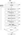
- FIG. 2 is a flowchart showing an overall outline of the processing executed by the controller 100.
- the controller 100 executes an initial process (S410). For example, after startup, an initial initialization (initial process, for example, before starting a normal operation (control process for each of the main axis servo system 200 and the slave axis servo system 300)). , Various setting processes necessary for normal operation).
- the controller 100 receives, as inputs, the FB values of the main axis and the sub-axis (that is, the FB position (main axis) and the FB position (sub-axis)) from each of the main axis servo system 200 and the sub-axis servo system 300 (S420). . Then, the command value generation unit 110 calculates a command value (eg, command position (spindle)) to the spindle servo driver 210 for each spindle-side control cycle from the target trajectory data of the spindle (S430).
- a command value eg, command position (spindle)
- the first predicting unit 120 predicts the future FB value of the spindle, that is, the “FB position (spindle) in the future spindle-side control cycle”, from the FB position (spindle) received in S420 (S440). Then, the first prediction unit 120 notifies the cam calculation unit 130 of the predicted “FB position (spindle) in the future spindle-side control cycle”.
- the cam calculation unit 130 calculates the future correspondence value (corresponding subordinate position) of the slave axis corresponding to the “FB position (spindle) in the future spindle control cycle” notified from the first prediction unit 120, that is, “future Command position (slave axis) in the slave axis control cycle of step (S450).
- the cam calculation unit 130 notifies the MPC unit 140 of the corresponding subordinate position calculated from the “FB position (main shaft) in the future main shaft side control cycle”.
- the MPC section 140 calculates a command value to the slave axis servo driver 310 using the dynamic characteristic model of the slave axis servo system 300 (S460), that is, the MPC using the dynamic characteristic model of the slave axis servo system 300 It is applied to the control of the slave axis servo system 300. Specifically, the MPC unit 140 calculates the “FB position (slave axis) in the future cycle (future slave-side control cycle)” predicted using the dynamic characteristic model of the slave axis servo system 300 in S450. A command speed (slave axis) is generated so as to match the corresponding dependent position.
- the controller 100 (specifically, each of the command value generation unit 110 and the MPC unit 140) sends the command value to the servo driver on the master axis side and the slave axis side (that is, the master axis servo driver 210 and the slave axis servo driver 310). It outputs (S470). That is, the command value generation unit 110 outputs a command position (spindle) to the spindle servo driver 210, and the MPC unit 140 outputs a command speed (slave axis) to the slave axis servo driver 310. Then, the controller 100 repeats the processing from S420 to S470 in each control cycle until the control ends (Yes in S480).
- control method executed by the controller 100 which has been described with reference to FIG. 2, can be summarized as follows. That is, the control method executed by the controller 100 is a control method of a control device that causes the position of the slave axis to follow the position of the master axis.
- the “predicted position of the slave axis in the future” predicted using the dynamic characteristic model of “300” is calculated in the “future future” calculated in the calculation step. That to match the corresponding slave position "includes a driven shaft command step (S460) for generating a driven shaft command value is a command value of the current for the slave axis servo system 300.
- the control method assumes that “the current acceleration of the FB position (spindle) continues to be constant for a predetermined period”, and the feedback position of the FB position (spindle) in the future is the feedback position of the spindle. Predict).
- control method is a method that corresponds to a future FB position (spindle) corresponding to a future FB position (spindle) from a future FB position (spindle) predicted without using a dynamic characteristic model of the spindle servo system 200. Calculate the subordinate position. Then, the control method uses an MPC using a dynamic characteristic model of the slave axis servo system 300 in which the calculated corresponding slave position (position of the slave axis in the future) is set as a future command value (command position) of the slave axis. Applies to slave axis control.
- the control method predicts the FB position (spindle) in the future, and sets the “corresponding subordinate position (future command value of the slave axis, command in the future cycle) corresponding to the predicted“ FB position (spindle) in the future ”.
- MPC using “position (slave axis)”) is applied to the control of the slave axis.
- the control method has an effect that the followability of the position control of the slave shaft is improved, and the position control of the slave shaft can be performed at high speed and with high accuracy.
- the control method has the effect of increasing the speed of operations of machines and the like controlled by the control method and contributing to an improvement in productivity at a production site using these machines.
- Embodiment 2 of the present invention will be described below with reference to FIGS.
- members having the same functions as the members described in the above embodiment are denoted by the same reference numerals, and description thereof will be omitted.
- the controller 100 has used “the current and past FB values of the spindle” for predicting the future FB value of the spindle.
- the controller 500 according to the present embodiment predicts the future FB value of the spindle using the “future command value of the spindle” in addition to the “current and past FB values of the spindle”. .
- the controller 500 that predicts the future FB value of the spindle using the “future command value of the spindle” is required to have a high command followability for the control of the spindle. That is, the prediction of the “future FB value of the spindle” using the “future command value of the spindle” is based on the assumption that the command value in the spindle control is highly responsive. More specifically, when the command control value of the spindle control is low, the change in the control deviation of the spindle becomes very slow with respect to the change in the command value, and the change in the control deviation and the change in the command value are combined. However, the prediction accuracy of the future FB value of the spindle will be low. Therefore, when predicting the "future FB value of the spindle" using the "future command value of the spindle", the ability to follow the command value of the spindle control is required to be considerably high.
- the controller 500 realizes high followability to the command value in the spindle control by applying MPC to the control of the spindle, and achieves a high-precision “spindle” using “future command value of the spindle”. Of the future FB value.
- the controller 500 improves the followability of the slave axis with respect to the master axis, so that the operation of the machines controlled by the controller 500 can be further accelerated. Contributes to improved productivity.
- the controller 500 is applied to electronic cam control, similarly to the controller 100 of the first embodiment.
- the application example of the controller 500 is not limited to the electronic cam control, but may be any control as long as it is “control that causes the position of the slave shaft to follow the position of the main shaft”.
- the details of the controller 500 will be described with reference to FIGS.
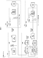
- FIG. 3 is a block diagram showing a main configuration of the controller 500 and the like.
- the control system 2 including the controller 500 will be described.
- the control system 2 illustrated in FIG. 3 includes a controller 500 which is a higher-order controller, and a main axis servo system 600 and a slave axis servo system 700 controlled by the controller 500.
- the spindle servo system 600 is a feedback control system including a spindle servo driver 610 and a machine 630 (for example, a motor and a mechanism) whose driving is controlled by the spindle servo driver 610.
- the slave axis servo system 700 is a feedback control system including a slave axis servo driver 710 and a machine 730 (for example, a motor and a mechanism) whose driving is controlled by the slave axis servo driver 710.
- the controller 500 is communicably connected to each of the master axis servo driver 610 and the slave axis servo driver 710, and the connection method is an arbitrary wired connection method or a wireless connection method.
- the spindle servo driver 610 controls the output (that is, the position of the spindle) of the machine 630 according to the “command value for the spindle” received from the controller 500 at every predetermined control cycle (spindle-side control cycle). Feedback control device.
- the output of the machine 630 is input to each of the spindle servo driver 610 and the controller 500 as the FB value of the spindle position (hereinafter, also referred to as “FB position (spindle)”).
- the spindle servo driver 610 sets the “command value for the spindle (command spindle value; for example, command speed (spindle))” from the controller 500 as the target value, and uses the FB obtained by time-differentiating the measured value (eg, the FB position (spindle)).
- the feedback control is performed on the machine 630 using the speed (spindle) as a feedback value. That is, the spindle servo driver 610 adjusts the current for driving the machine 630 (particularly, a servomotor included in the machine 630) such that the measured value approaches the target value.
- the spindle servo driver 610 may be called a servo motor amplifier.
- the spindle servo driver 610 in FIG. 3 includes a speed controller 620 that performs proportional-integral control (PI control), and receives a “command speed for the spindle (hereinafter, also referred to as“ command speed (spindle) ”)” from the controller 500. I do.
- the speed control unit 620 calculates a command torque (spindle) from a speed deviation (spindle) which is a deviation between the command speed (spindle) received from the controller 500 and the FB speed (spindle) calculated by differentiating the FB position (spindle). ).
- the spindle servo driver 610 controls the machine 630 based on the generated command torque (spindle).
- the slave axis servo driver 710 outputs the output of the machine 730 (that is, the slave axis) in accordance with the “command value for the slave axis” received from the controller 500 at every predetermined control cycle (slave axis side control cycle). Is a feedback control device for controlling the position of the feedback control.
- the output of the machine 730 is input to each of the slave axis servo driver 710 and the controller 500 as the FB value of the slave axis position (hereinafter, also referred to as “FB position (slave axis)”).
- the slave axis servo driver 710 sets the “command value for the slave axis (eg, command speed (slave axis))” from the controller 500 as the target value, and uses the FB obtained by time-differentiating the actual measurement value (eg, the FB position (slave axis)).
- the speed (slave axis) is used as a feedback value to perform feedback control on the machine 730. That is, the slave axis servo driver 710 adjusts the current for driving the machine 730 (particularly, the servomotor included in the machine 730) such that the measured value approaches the target value.
- the slave axis servo driver 710 may be referred to as a servo motor amplifier.
- the slave axis servo driver 710 in FIG. 3 includes a speed control unit 720 that performs proportional-integral control (PI control), and receives a command speed for the slave axis (hereinafter, also referred to as “command speed (slave axis)”) from the controller 500. Is received.
- the speed controller 720 determines a speed deviation (deviation) between the command speed (slave axis) received from the controller 500 and the FB speed (slave axis) calculated by differentiating the FB position (slave axis) acquired by an encoder or the like. From the slave axis), a command torque (slave axis) is generated.
- the slave axis servo driver 710 controls the machine 730 based on the generated command torque (slave axis).
- the controller 500 controls the entire control system 2 including the master axis servo system 600 and the slave axis servo system 700, and is, for example, a programmable controller (PLC, Programmable Logic Controller).
- PLC Programmable Logic Controller
- the controller 500 outputs a command value to each of the master axis servo system 600 and the slave axis servo system 700, and controls each of the master axis servo system 600 and the slave axis servo system 700.
- the controller 500 controls the spindle servo system 600 by, for example, outputting a “command speed (spindle)” that is a command speed for the spindle to the spindle servo system 600 in each spindle-side control cycle.
- the controller 500 applies the MPC using the dynamic characteristic model of the spindle servo system 600 to control the spindle servo system 600.
- the controller 500 outputs the “command speed (sub-axis)”, which is the command speed for the sub-axis, to the sub-axis servo system 700 for each sub-axis control cycle, and controls the sub-axis servo system 700. I do.
- the controller 500 applies MPC using the dynamic characteristic model of the slave axis servo system 700 to control the slave axis servo system 700.
- the control cycle (spindle-side control cycle) of the controller 500 for the spindle servo system 600 and the control cycle (slave-axis control cycle) of the controller 500 for the slave axis servo system 700 may be the same or may be the same time. It is not necessary.
- the slave axis side control cycle may be shorter than the master axis side control cycle, that is, the slave axis side control cycle may be faster than the master axis side control cycle.
- the controller 500 acquires the FB value from the master axis servo system 600 and the slave axis servo system 700 and uses the FB value for controlling the master axis servo system 600 and the slave axis servo system 700.
- the controller 500 acquires, for example, the FB position (spindle), which is the output of the machine 630 (that is, the position of the spindle), from the spindle servo system 600 and uses the FB position for controlling the spindle servo system 600 and the slave axis servo system 700.
- the controller 500 acquires, for example, an FB position (slave axis), which is the output of the machine 730 (ie, the position of the slave axis), from the slave axis servo system 700 and uses the FB position for controlling the slave axis servo system 700.
- an FB position slave axis
- the controller 500 acquires, for example, an FB position (slave axis), which is the output of the machine 730 (ie, the position of the slave axis), from the slave axis servo system 700 and uses the FB position for controlling the slave axis servo system 700.
- the controller 500 uses the “FB value and the command value” in each of the past and present spindle-side control cycles of the spindle and the command value in the future spindle-side control cycle to determine the FB in the future spindle-side control cycle. Predict the value.
- the controller 500 uses the “FB position (spindle) and command position (spindle)” in each of the past and present spindle-side control cycles of the spindle and the command position (spindle) in the future spindle-side control cycle.
- the FB position (spindle) in the future spindle-side control cycle is predicted.
- the controller 500 assumes that “the rate of change with time of the position deviation (deviation between the FB position (spindle) and the command position (spindle)) in the current spindle-side control cycle of the spindle continues with time”. Then, the “position deviation in the future spindle-side control cycle of the spindle” is calculated.
- the controller 500 executes the following processing, assuming that “the rate of change of the position deviation in the current spindle-side control cycle with respect to time continues to be constant in the future”. That is, the controller 500 calculates the position deviation in each of the current and past spindle-side control cycles using the “FB position (spindle) and the command position (spindle)” in each of the current and past spindle-side control cycles. . Then, the controller 500 calculates the position deviation change rate in the current spindle-side control cycle from the calculated “position deviation in each of the present and past spindle-side control cycles”.
- the controller 500 calculates the "position deviation in the future spindle-side control cycle", assuming that the "position deviation change rate in the current spindle-side control cycle” is constant and continues. That is, under the above-described assumption, the controller 500 determines, based on the time interval (cycle time) corresponding to the spindle-side control cycle and the “position deviation and the position deviation change rate in the current spindle-side control cycle,” "Position deviation in the spindle-side control cycle" is calculated.
- the controller 500 calculates the FB position (spindle in the future spindle-side control cycle) from the calculated “position deviation in the future spindle-side control cycle” and the “command position (spindle) in the future spindle-side control cycle”. ) ”, That is, the future FB value of the main axis is predicted.
- the controller 500 calculates a future command value of the slave axis (that is, a command position in the future cycle (slave axis)) corresponding to the predicted future FB value of the spindle (that is, the FB position (spindle) in the future cycle). That is, the corresponding dependent position) is calculated.
- the MPC is executed for the slave axis servo system 700.
- the controller 500 applies the MPC using the dynamic characteristic model of the spindle servo system 600 to the control of the spindle, that is, executes the MPC for the spindle servo system 600.
- the controller 500 is a control device that causes the position of the slave shaft to follow the position of the main shaft, and includes a second predicting unit 530 (predicting unit), a cam calculating unit 540 (calculating unit), 2MPC section 550 (slave axis command section).
- the second prediction unit 530 calculates the difference between the command position (spindle) (ie, the spindle command position), which is the command position generated from the target trajectory of the spindle, and the FB position (spindle) (ie, the spindle feedback position).
- the FB position (main axis) in the future is predicted on the assumption that the current time change rate of a certain position deviation (also referred to as “position deviation (main axis)”) continues to be constant over a predetermined period.
- the cam calculating section 540 calculates a corresponding subordinate position that is “the position of the slave axis in the future” corresponding to the “FB position (main axis) in the future” predicted by the second predicting section 530.
- the second MPC unit 550 calculates the “predicted position of the slave axis in the future”, which is predicted using the dynamic characteristic model of the slave axis servo system 700 that performs the feedback control of the position of the slave axis, by the cam calculation unit 540.
- a slave axis command value that is a current command value for the slave axis servo system 700 is generated so as to match the “corresponding dependent position”.
- the controller 500 predicts the FB position (main axis) in the future on the assumption that the current time change rate of the position deviation (main axis) remains constant over a predetermined period. .
- the controller 500 converts the “future FB position (spindle)” predicted without using the dynamic characteristic model of the spindle servo system 600 from the “future FB position (spindle)” to the “future FB position (spindle)”.
- a corresponding subordinate position which is a "position” is calculated.
- the controller 500 uses the dynamic characteristic model of the slave axis servo system 700 in which the calculated “corresponding dependent position (position of the slave axis in the future)” is “future command value of the slave axis (command position)”. MPC is applied to the control of the slave axis.
- the controller 500 predicts the FB position (spindle) in the future, and sets the “corresponding subordinate position (future command value of the slave axis, command position in the future cycle) corresponding to the predicted“ FB position (spindle) in the future ”. (Slave)) is applied to the control of the slave.
- the controller 500 has an effect that the followability of the position control of the slave shaft is improved, and the speed control and the accuracy of the position control of the slave shaft can be increased.
- the controller 500 has the effect of increasing the speed of operations of machines and the like controlled by the controller 500 and contributing to an improvement in productivity at a production site using these machines.
- the controller 500 causes the position of the slave shaft to follow the position of the main shaft, for example.
- the second prediction unit 530 calculates the position deviation (ie, the position deviation (spindle)) of the deviation between the command position (spindle) and the FB position (spindle) in each cycle (each spindle-side control cycle).
- the rate of change with respect to time is constant over a plurality of cycles, "and the" FB position (spindle) in each of the current and past cycles (each spindle-side control cycle) "and” past, present, and
- the controller 500 includes “the FB position (spindle) in each of the present and past cycles (each spindle-side control cycle)” and “the past, present, and future cycles (each spindle-side control cycle). FB position (spindle) in a future cycle (spindle-side control cycle).
- the controller 500 calculates a position deviation (spindle) in the current cycle (spindle control cycle) from the difference between the command position (spindle) and the FB position (spindle) in the current cycle (spindle control cycle). .
- the controller 500 determines, in the cycle immediately before the present cycle (spindle-side control cycle), the difference between the command position (spindle) and the FB position (spindle) in the cycle immediately before the present cycle (spindle-side control cycle). Calculate the position deviation (spindle).
- the controller 500 determines the difference between the position deviation (spindle) in the current cycle (spindle-side control cycle) and the position deviation (spindle-side control cycle) one cycle before the current cycle (spindle-side control cycle) in the cycle (the spindle (control axis)).
- the “current period (spindle-side control period) divided by the period time, which is the time interval of the current period (spindle-side control period) shows the“ current period (change) of the position deviation (spindle axis) with respect to time (rate) ”.
- Position change rate in the spindle-side control cycle) is calculated.
- the controller 500 assumes that the calculated “rate of change in position deviation in the current cycle (spindle-side control cycle)” will continue to be constant in a future cycle (spindle-side control cycle), and assumes that the cycle time, “current cycle” (Position deviation change rate in main axis control cycle) and position deviation (main axis) in current cycle (main axis control cycle) from position deviation (main axis) in future cycle (main axis control cycle) Is calculated.
- the controller 500 obtains a difference between the "command position (spindle) in the future cycle (spindle-side control cycle)" and the calculated “position deviation (spindle) in the future cycle (spindle-side control cycle)".
- the FB position (spindle) in the future cycle (spindle-side control cycle) is predicted.
- the controller 500 calculates the corresponding subordinate position that is the position of the slave axis in the future cycle (that is, the commanded position (slave axis)) corresponding to the predicted “FB position (main axis) in the future cycle”.
- the controller 500 uses the MPC using the dynamic characteristic model of the slave axis servo system 700 with the calculated corresponding slave position as the “future slave axis command value (command position (slave axis))” for the slave axis control. Apply.
- the controller 500 predicts the MPC applied to the control of the slave axis using the “current and past FB positions (spindle)” and the “past, present, and future command positions (spindle)”.
- the “future command position (slave axis) that is, corresponding subordinate position” corresponding to the “future FB position (spindle axis)” is used.
- the controller 500 can improve the followability of the position control of the slave shaft in the control device that makes the position of the slave shaft follow the position of the master shaft, and can increase the speed and accuracy of the position control of the slave shaft. It has the effect of being able to do it.
- the controller 500 controls the spindle servo system 600 so that the “prediction position of the spindle in the future” predicted using the dynamic characteristic model of the spindle servo system 600 matches the command position (spindle) in the future.
- a first MPC unit 520 spindle command unit that generates a command spindle value (also referred to as “command speed (spindle)”).
- the controller 500 controls the spindle servo system so that the “prediction position of the spindle in the future” predicted using the dynamic characteristic model of the spindle servo system 600 matches the command position (spindle) in the future.
- a current command value (command speed (spindle)) for 600 is generated.
- the controller 500 has an effect that the followability of the position control of the spindle can be improved.
- the controller 500 applies MPC using the dynamic characteristic model of the spindle servo system 600 to control the position of the spindle, thereby improving the followability of the position control of the spindle.
- the controller 500 improves the followability of the position control of the spindle by the MPC, and uses the FB position (spindle) in the future predicted using the command position (spindle) in the future to perform the position control of the slave axis. This has the effect that the followability can be improved.
- the main axis is the main axis of the electronic cam
- the sub axis is the sub axis of the electronic cam.
- the cam calculation unit 540 calculates, for example, “the position of the slave axis of the electronic cam in the future” corresponding to “the phase (position) of the main axis of the electronic cam in the future” predicted by the second prediction unit 530.
- the controller 500 calculates the “position of the slave axis of the electronic cam in the future” corresponding to the predicted “phase of the spindle of the electronic cam in the future”.
- the controller 500 determines that the current time change of the position deviation (spindle), which is the deviation between the command position (spindle), which is the command position generated from the target trajectory of the spindle of the electronic cam, and the FB position (spindle). Assuming that the rate will remain constant for a predetermined period of time, "a feedback position (feedback phase) of the main shaft of the electronic cam in the future is predicted.
- the controller 500 predicts the position of the future main shaft of the electronic cam without using the dynamic characteristic model of the main shaft servo system 600. Then, the controller 500 calculates the “position of the future slave axis of the electronic cam (corresponding dependent position)” corresponding to the predicted “position of the future main axis of the electronic cam”. The controller 500 controls the position of the slave axis of the electronic cam using the calculated corresponding slave position (specifically, MPC is applied to position control of the slave axis of the electronic cam).
- the controller 500 predicts the FB position (spindle) in the future, and converts the MPC using the “future command value of the slave axis of the electronic cam” corresponding to the predicted “FB position (spindle) in the future” to the slave axis. Apply to control.
- the controller 500 improves the followability of the position control of the slave shaft with respect to the position (phase) of the main shaft of the electronic cam, and controls the position control of the slave shaft. This has the effect of increasing speed and accuracy.
- the controller 500 obtains the corresponding “future position of the slave axis of the electronic cam, the corresponding slave position” from the “future feedback position of the spindle of the electronic cam” predicted without using the dynamic characteristic model of the spindle servo system 600. Is calculated. Then, the controller 500 uses the dynamic characteristic model of the slave axis servo system 700 in which the calculated “corresponding dependent position (position of the slave axis in the future)” is “future command value of the slave axis (command position)”. MPC is applied to the control of the slave axis. Accordingly, the controller 500 has an effect that the followability of the position control of the slave shaft of the electronic cam can be improved, and the position control of the slave shaft can be speeded up and highly accurate.
- the controller 500 includes, as functional blocks, a command value generation unit 510, a first MPC unit 520, a second prediction unit 530, a cam calculation unit 540, a second MPC unit 550, and a monitoring unit 560.
- a command value generation unit 510 As illustrated in FIG. 3, the controller 500 includes, as functional blocks, a command value generation unit 510, a first MPC unit 520, a second prediction unit 530, a cam calculation unit 540, a second MPC unit 550, and a monitoring unit 560.
- a command value generation unit 510 As illustrated in FIG. 3, the controller 500 includes, as functional blocks, a command value generation unit 510, a first MPC unit 520, a second prediction unit 530, a cam calculation unit 540, a second MPC unit 550, and a monitoring unit 560.
- the controller 500 may have the omitted configuration in accordance with the actual situation of implementation.
- a storage device (storage unit 570) in which a CPU (central processing unit) or the like is realized by a ROM (read only memory), an NVRAM (non-Volatile random access memory), or the like. This can be realized by reading a stored program into a RAM (random access memory) or the like (not shown) and executing it.
- a CPU central processing unit
- NVRAM non-Volatile random access memory
- Command value generation section 510 is similar to command value generation section 110, receives target trajectory data of the spindle from the outside, and issues a command value (specifically, a command position) for each spindle-side control cycle from the received target trajectory data. (Spindle)). Then, command value generation section 510 outputs the generated command position (spindle) to first MPC section 520 and second prediction section 530.
- the first MPC unit 520 applies MPC using a dynamic characteristic model of the spindle servo system 600 to control the spindle servo system 600.
- first MPC section 520 performs MPC (model predictive control) on spindle servo system 600 using a dynamic characteristic model of spindle servo system 600 (a dynamic characteristic model of spindle servo driver 610 and machine 630).
- the first MPC unit 520 uses the command position (spindle) generated by the command value generation unit 510 and the FB position (spindle) acquired from the spindle servo system 600 to operate the spindle servo system 600.
- a command speed (spindle) is generated by MPC using a characteristic model.
- the first MPC unit 520 has, as an internal model, a model of the spindle servo driver 610 and the machine 630 (that is, a dynamic characteristic model of the spindle servo system 600).
- FB position (spindle) in the control cycle) is predicted.
- the first MPC unit 520 predicts “FB position (spindle) in a future spindle-side control cycle” by using the FB position (spindle) acquired so far by the dynamic characteristic model of the spindle servo system 600. I do.
- the first MPC unit 520 determines the current “FB position (spindle) in the future cycle” to match the command position (spindle) generated by the command value generation unit 510 with respect to the current spindle servo system 600.
- a command value in a cycle (for example, a command speed (spindle)) is generated.
- the first MPC unit 520 sets the command speed (spindle speed) in the current spindle control cycle such that the predicted “FB position (spindle) in the future cycle” matches the command position (spindle) generated from the target trajectory data of the spindle. ).
- the first MPC section 520 outputs the generated “command speed (spindle) in the current spindle control cycle” to the spindle servo system 600 (specifically, the spindle servo driver 610) in the current spindle control cycle.
- the first MPC unit 520 that applies the MPC using the dynamic characteristic model of the spindle servo system 600 to control the spindle servo system 600 also applies dynamic friction compensation to the control of the spindle servo system 600.
- the dynamic friction compensation may be applied to the control of each of the slave axis servo system 300 and the slave axis servo system 700 in each of the MPC unit 140 described above and the second MPC unit 550 described below.
- the first MPC unit 520 outputs a command speed (spindle) to the spindle servo driver 610 for the control of the spindle servo system 600, so that the spindle servo driver 610 operates at a high speed (that is, faster than the spindle-side control cycle). )
- a command speed spindle
- the command value generation unit 110 in the controller 100 does not apply MPC or dynamic friction compensation to control the spindle servo system 200.
- the dynamic friction compensation may be performed not only on the servo driver side as described above, but also on the controller side, that is, on the controller 100 and the controller 500 side.
- the second prediction unit 530 outputs, from the command value generation unit 510, a command value (specifically, a command position (spindle)) generated by the command value generation unit 510 from the target trajectory data for each spindle-side control cycle.
- a command value specifically, a command position (spindle)
- the command value in each of the past, present, and future spindle-side control cycles is obtained.
- FB value of the main spindle is predicted using the position deviation of the spindle.
- the second prediction unit 530 Execute
- the second predicting unit 530 determines the “spindle command position (SP n in the above equation) in the current spindle side control cycle” and the “FB position (spindle) in the current spindle side control cycle (PV n in the above equation). )), The “position deviation (ER n ) in the current spindle-side control cycle” is calculated.
- the second prediction unit 530 calculates “the spindle command position (SP n ⁇ 1 in the above equation) in the spindle control cycle one cycle before the present” and “FB position in the spindle control cycle one cycle before the present”. (Spindle) (PV n ⁇ 1 in the above equation) ”, and calculates the“ position deviation (ER n ⁇ 1 ) in the spindle-side control cycle one cycle before the current cycle ”.
- the second prediction unit 530 calculates the difference between the “position deviation (ER n ) in the current spindle-side control cycle” and the “position deviation (ER n ⁇ 1 ) in the spindle-side control cycle one cycle before the current cycle”. Is divided by the cycle time Ts, which is the time interval of the spindle-side control cycle, to obtain a "position (change) of the position deviation in the current spindle-side control cycle with respect to time”. Deviation change rate (ERd in the above equation) "is calculated.
- the second predicting unit 530 calculates the difference between the “spindle command position (SP i in the above equation) in the spindle-side control cycle after i cycles” and the calculated “position error (ER i ) after i cycles”. , The FB position (spindle) (PVpr (i) in the above equation) in the spindle-side control cycle after the i-th cycle is predicted.
- the second prediction unit 530 notifies the cam operation unit 540 of the “FB position (spindle) in the future spindle-side control cycle” for each predicted spindle-side control cycle, and the predicted spindle position table 571 of the storage unit 570. To be stored.
- the cam calculation unit 540 calculates the “command position (slave axis) in the future slave axis control cycle” corresponding to the “FB position (spindle) in the future spindle axis control cycle” notified from the second prediction unit 530. I do.
- the “command position (slave axis) in the future slave axis control cycle” calculated from the “FB position (spindle axis) in the future spindle axis control cycle” by the cam calculation unit 540 is also referred to as the “corresponding slave position”. Name.
- the cam calculation unit 540 calculates the corresponding subordinate position using, for example, master-slave relationship information (for example, a so-called “cam table”) that is an “array in which the position of the slave shaft is associated with the position of the master shaft”. .
- the cam calculation unit 540 may calculate the corresponding subordinate position using an “operation formula (for example, a so-called“ cam operation formula ”) in which the position of the slave shaft is associated with the position of the main shaft.
- the cam calculation unit 540 only needs to be able to calculate the corresponding subordinate position using a known technique, and the method of calculating the corresponding subordinate position is not particularly limited.
- the cam calculation unit 540 calculates the “command in the future slave axis control cycle corresponding to the“ FB position (spindle) in the future spindle axis control cycle ”” calculated from the “FB position (spindle) in the future spindle axis control cycle”. Position (slave axis) "to the second MPC unit 550.
- the second MPC unit 550 performs MPC (model predictive control) for the slave axis servo system 700 using the dynamic characteristic model of the slave axis servo system 700. Specifically, the second MPC section 550 uses the corresponding subordinate position calculated by the cam operation section 540 and the FB position (subordinate axis) acquired from the subordinate axis servo system 700 to operate the slave axis servo system 700. A command speed (slave axis) is generated by MPC using a characteristic model.
- the second MPC unit 550 has a model of the slave axis servo driver 710 and the machine 730 (that is, a dynamic characteristic model of the slave axis servo system 700) as an internal model.
- the FB position (slave axis) in the slave axis side control cycle) is predicted.
- the second MPC unit 550 uses the dynamic characteristic model of the slave axis servo system 700 to obtain the “FB position (slave axis) acquired so far” and the “command output to the slave axis servo driver 710 so far.
- FB position (slave axis) in the future slave axis side control cycle is predicted using the" value (slave axis) ".
- the second MPC unit 550 sends the current cycle to the slave axis servo system 700 such that the predicted “FB position (slave axis) in the future cycle” matches the corresponding slave position calculated by the cam calculation unit 540.
- a command speed (slave axis) For example, a command speed (slave axis)
- the second MPC unit 550 determines that the predicted “FB position (slave axis) in the future cycle” corresponds to the “FB position (slave axis) in the future spindle-side control cycle” in the “command position (future slave axis control cycle)”.
- Command speed (slave axis) in the current slave axis control cycle so as to coincide with "slave axis").
- the second MPC unit 550 transmits the generated “command speed (subordinate axis) in the current subordinate control cycle” to the subordinate servo system 700 (specifically, the subordinate servo driver 710) in the current subordinate control cycle.
- the monitoring unit 560 is the same as the monitoring unit 150, and thus details are omitted.
- the storage unit 570 and the predicted spindle position table 571 stored in the storage unit 570 are the same as the storage unit 160 and the predicted spindle position table 161 stored in the storage unit 160, respectively. Is abbreviated. In other words, in the predicted spindle position table 571, the “FB position (spindle in the future spindle-side control cycle) for each spindle-side control cycle, predicted by the second prediction section 530 by the second prediction section 530, in each spindle-side control cycle. ) "Is stored.
- the monitoring unit 560 monitors the “FB position (spindle) in the future spindle-side control cycle” predicted by the second prediction unit 530, and, for example, for a plurality of cycles stored in the predicted spindle position table 571.
- the “FB position (spindle) in the future spindle-side control cycle” is monitored.
- the monitoring unit 560 detects a change in the “FB position (spindle) in the future spindle-side control cycle” by monitoring the temporal change of the “FB position (spindle) in the future spindle-side control cycle”. To understand the tendency of fluctuation and occurrence of sudden fluctuation.
- FIG. 4 is a flowchart showing an overall outline of the processing executed by the controller 500.
- the controller 500 first executes an initial process (S810). For example, after startup, an initial initialization (initial process, for example, before starting a normal operation (control process for each of the main axis servo system 600 and the slave axis servo system 700)). , Various setting processes necessary for normal operation).
- the controller 500 receives, as inputs, the FB values of the master axis and the slave axis (that is, the FB position (master axis) and FB position (slave axis)) from each of the master axis servo system 600 and the slave axis servo system 700 (S820). . Then, the command value generator 510 calculates a command value (eg, a command position (spindle)) to the spindle servo driver 610 for each spindle-side control cycle from the target trajectory data of the spindle (S830). Command value generation section 510 outputs the generated command position (spindle) to first MPC section 520 and second prediction section 530.
- a command value eg, a command position (spindle)
- the first MPC unit 520 notified of the command position (spindle) from the command value generation unit 510 uses the MPC using the dynamic characteristic model of the spindle servo system 600 to issue a command value (eg, command speed (spindle)) to the spindle servo driver 610. Is calculated (S840).
- a command value eg, command speed (spindle)
- the cam calculation unit 540 calculates the future correspondence value (corresponding subordinate position) of the slave axis corresponding to the “FB position (spindle) in the future spindle-side control cycle” notified from the second prediction unit 530, that is, “future Command position (slave axis) in the slave axis control cycle of step S860) is calculated (S860).
- the cam calculation unit 540 notifies the second MPC unit 550 of the corresponding subordinate position calculated from the “FB position (main shaft) in the future main shaft control cycle”.
- the second MPC unit 550 calculates a command value to the slave servo driver 710 using the dynamic characteristic model of the slave servo system 700 (S870), that is, the MPC using the dynamic characteristic model of the slave servo system 700. Is applied to the control of the slave axis servo system 700. Specifically, the second MPC unit 550 calculates the “FB position (slave axis) in the future cycle (slave axis side control cycle)” predicted using the dynamic characteristic model of the slave axis servo system 700 in S860. A command speed (slave axis) is generated so as to match the corresponding slave position.
- the controller 500 (specifically, each of the first MPC unit 520 and the second MPC unit 550) sends a command value to the main-axis and sub-axis servo drivers (that is, the main-axis servo driver 610 and the sub-axis servo driver 710). It outputs (S880). That is, the first MPC unit 520 outputs a command speed (spindle) to the spindle servo driver 610, and the second MPC unit 550 outputs a command speed (slave axis) to the slave axis servo driver 710. Then, the controller 500 repeats the processing from S820 to S880 every control cycle until the control ends (Yes in S890).
- control method executed by the controller 500 is a control method of the control device that causes the position of the slave axis to follow the position of the spindle, and includes the “command position (the spindle position that is a command position generated from the target trajectory of the spindle). ) (Ie, the spindle command position) and the position deviation (ie, position deviation (spindle)), which is the deviation between the FB position (spindle), assume that the current time rate of change remains constant over a predetermined period.
- the control method predicts an FB position (main axis) in the future on the assumption that the current time change rate of the position deviation (main axis) remains constant for a predetermined period. I do.
- the control method uses the “future FB position (spindle)” corresponding to the “future FB position (spindle)” predicted without using the dynamic characteristic model of the spindle servo system 600.
- the corresponding subordinate position is calculated.
- the control method uses a dynamic characteristic model of the slave axis servo system 700 in which the calculated “corresponding slave position (position of the slave axis in the future)” is set as “future command value (command position) of the slave axis”.
- the applied MPC is applied to the control of the slave axis.
- the control method predicts the FB position (spindle) in the future, and sets the “corresponding subordinate position (future command value of the slave axis, command in the future cycle) corresponding to the predicted“ FB position (spindle) in the future ”.
- MPC using “position (slave axis)”) is applied to the control of the slave axis.
- the control method has an effect that the followability of the position control of the slave shaft is improved, and the position control of the slave shaft can be performed at high speed and with high accuracy.
- the control method has the effect of increasing the speed of operations of machines and the like controlled by the control method and contributing to an improvement in productivity at a production site using these machines.
- Embodiment 3 of the present invention will be described below with reference to FIG.
- members having the same functions as the members described in the above embodiment will be denoted by the same reference numerals, and the description thereof will be omitted.
- FIG. 5 is a block diagram illustrating a main configuration of a controller 900 and the like according to the third embodiment.
- the controller 900 is different from the controller 500 according to the second embodiment in one of the following points, and is similar to the controller 500 in other points. That is, the controller 900 includes the first prediction unit 120 of the controller 100 instead of the second prediction unit 530 of the controller 500, and the other configuration is the same as that of the controller 500.
- the first prediction unit 120 notifies the cam operation unit 540 of the “FB position (spindle) in the future spindle-side control cycle” for each predicted spindle-side control cycle, and the predicted spindle position table 571 of the storage unit 570. To be stored.
- the cam calculator 540 calculates the “command position (slave axis) in the future slave axis control cycle” corresponding to the “FB position (spindle) in the future spindle axis control cycle” notified from the first predictor 120. I do.
- the processing executed by the controller 900 is also the same as that of the controller 500. Is almost the same as the process executed by
- the second prediction unit 530 determines whether the FB position (spindle) received in S820 and the “past, present, and future spindle-side control cycles” acquired from the command value generation unit 510. , The future FB value of the spindle is predicted.
- the controller 900 executes the following processing.
- the first prediction unit 120 of the controller 900 predicts a future FB value of the spindle, that is, “FB position (spindle) in a future spindle-side control cycle”, from the FB position (spindle) received in S820. (S850 '). Then, the first prediction unit 120 notifies the cam calculation unit 540 of the predicted “FB position (spindle) in the future spindle-side control cycle”. After that, the controller 900 executes the processing from S860 to S890 in FIG.
- FIG. 6 shows a sinusoidal torque applied to the spindle control (for example, the spindle servo system 200 in the control system 1, the spindle servo system 600 in the control system 2, and the spindle servo system 600 in the control system 3) in the simulation 1. It is a figure showing a disturbance. As illustrated in FIG. 6, in a simulation 1 described below, the disturbance applied to the control of the main shaft is a sine wave torque disturbance having an amplitude of 50% and a frequency of 10 Hz.
- FIG. 7 is a diagram illustrating slave axis control realized by the conventional controller and the controllers according to the embodiments (that is, the controllers 100, 500, and 900) when the disturbance shown in FIG. 6 is applied.
- the conventional controller and the controller according to each embodiment are designed to make the main shaft and the slave shaft perform the same operation, and when the disturbance shown in FIG. FIG. 7 shows the result of the slave axis control described above.
- FIG. 7 shows the “command position” and “command position” when the disturbance shown in FIG. "Position deviation” and “torque” are shown in order. It is assumed that the conventional controller controls the slave axis in the control of the slave axis, assuming that the current command value continues in the prediction section.
- FIG. 7B shows, in the controller 100, the “command position”, the “position deviation”, and the “torque” when the disturbance shown in FIG. 6 is applied to the spindle servo system 200 in order.
- FIG. 7C shows, in the controller 900, the “command position”, the “position deviation”, and the “torque” when the disturbance shown in FIG. 6 is applied to the spindle servo system 600 in order.
- FIG. 7D shows, in the controller 500, the “command position”, the “position deviation”, and the “torque” when the disturbance shown in FIG. 6 is applied to the spindle servo system 200 in order.
- the "command position” in each of FIGS. 7A to 7D indicates a command position on the slave shaft side, and specifically, the FB position of the main shaft (that is, the FB position (main shaft)). ).
- the “position deviation” in each of (A) to (D) of FIG. 7 indicates the FB position of the main shaft (that is, the FB position (main shaft); in other words, the “command position” to the slave shaft described above). It shows a deviation from the FB position of the slave axis (that is, the FB position (slave axis)).
- “torque” in each of FIGS. 7A to 7D indicates a torque output from a feedback control system (for example, the slave servo system 300 or the slave servo system 700) that controls the slave axis. I have.
- the controllers 500 and 900 that apply the MPC using the dynamic characteristic model of the spindle servo system 600 to control the spindle servo system 600 also apply dynamic friction compensation to the control of the spindle servo system 600.
- the controller 100 does not apply the MPC nor the dynamic friction compensation to the control of the spindle servo system 200.
- controllers 100, 500, and 900 ((B), (D), and (C) of FIG. 7, respectively)
- the followability is greatly improved.
- the “position deviation” in each of FIGS. 7B, 7D, and 7C is significantly reduced as compared with the “position deviation” in FIG. 7A. This indicates that the prediction of the future FB position (spindle), that is, the prediction of the future “command position” on the slave axis side has a great effect on the control of the slave axis.
- the “position deviation” is large due to the influence of friction at “at the start of operation” at time 0 s and “at the time of operation direction reversal” at 0.25 s, 0.5 s, and 0.75 s after the start of operation. Prone.
- “position deviation” is large as a whole, and cannot be confirmed because the range of the graph is large.
- “operation” It can be seen that the "position deviation” is large at "at the start” and "at the time of reversing the operation direction”.
- FIG. 7C corresponding to the controller 900
- the “position deviation” of “at the time of operation inversion (and at the time of operation start)” is suppressed. Have been. This is because the change in acceleration of the FB value of the spindle (specifically, the FB position (spindle)) is reduced because the controller 900 applies dynamic friction compensation to the spindle control.
- the prediction of the future FB position (spindle) uses the acceleration information of the FB position (spindle) or the position deviation of the spindle (that is, the FB position). It is considered that the difference is whether to use the rate of change between the (main spindle) and the command position (the main spindle).
- the controller 900 includes a first prediction unit 120 of the controller 100 instead of the second prediction unit 530 of the controller 500. Then, the first prediction unit 120 of the controller 900 uses the “FB position (spindle) in each of the present and past spindle-side control cycles” to predict the FB position (spindle) in the future spindle-side control cycle, It does not use the "change rate of spindle position deviation".
- the second predicting unit 530 of the controller 500 assumes that the rate of change of the position deviation in each spindle-side control cycle of the spindle with respect to time is constant over a plurality of cycles, and that the future spindle-side control The FB position (main axis) in the cycle is predicted.
- the controller 500 uses the “change rate of the spindle position deviation” to predict the future FB position (spindle). (Principal axis). Due to the difference between the controller 500 and the controller 900 regarding the method of predicting the future FB position (spindle), the “position deviation” of “at the time of operation reversal (and at the start of operation)” is smaller than that of FIG. In (D) of FIG. 7, it is considered that it is suppressed more.
- FIG. 8 shows pulse-like torque applied to control of the spindle (for example, the spindle servo system 200 in the control system 1, the spindle servo system 600 in the control system 2, and the spindle servo system 600 in the control system 3) in the simulation 2. It is a figure showing a disturbance. As illustrated in FIG. 8, in Simulation 2 described below, a pulse-shaped torque disturbance having a magnitude of 200% and a time width of 50 ms is applied to control the main shaft at a time of 0.3 s.
- FIG. 9 is a diagram illustrating slave axis control realized by the conventional controller and the controllers according to the embodiments (that is, the controllers 100, 500, and 900) when the disturbance shown in FIG. 8 is applied.
- the conventional controller and the controllers according to the respective embodiments try to make the main axis and the slave axis perform the same operation as in the simulation 1.
- FIG. 9 shows the result of the slave axis control of each controller when the disturbance shown in FIG. 8 is applied to the control of the main axis in the simulation 2.
- FIG. 9 shows a conventional controller (that is, a controller that does not predict “future feedback value of the spindle”), “command position” and “command position” when the disturbance shown in FIG. 8 is applied to the spindle control. "Position deviation” and “torque” are shown in order. It is assumed that the conventional controller controls the slave axis in the control of the slave axis, assuming that the current command value continues in the prediction section.
- FIG. 9B shows the “command position”, “position deviation”, and “torque” of the controller 100 when the disturbance shown in FIG. 8 is applied to the main spindle servo system 200 in order.
- FIG. 9C shows, in the controller 900, the “command position”, the “position deviation”, and the “torque” when the disturbance shown in FIG. 8 is applied to the spindle servo system 600 in order.
- (D) sequentially shows “command position”, “position deviation”, and “torque” when the disturbance shown in FIG. 8 is applied to the spindle servo system 200 for the controller 500.
- the “command position” in each of FIGS. 9A to 9D indicates a command position on the slave shaft side, and specifically, the FB position of the main shaft (that is, the FB position (main shaft)). ).
- the “position deviation” in each of FIGS. 9A to 9D corresponds to the FB position of the main shaft (that is, the FB position (main shaft); in other words, the “command position” to the slave shaft described above). It shows a deviation from the FB position of the slave axis (that is, the FB position (slave axis)).
- “torque” in each of (A) to (D) of FIG. 9 indicates a torque output from a feedback control system (for example, the slave axis servo system 300 or the slave axis servo system 700) for controlling the slave axis. I have.
- the controllers 500 and 900 that apply the MPC using the dynamic characteristic model of the spindle servo system 600 to control the spindle servo system 600 also apply dynamic friction compensation to the control of the spindle servo system 600.
- the controller 100 does not apply the MPC nor the dynamic friction compensation to the control of the spindle servo system 200.
- controllers 100, 500, and 900 (FIGS. 9B, 9D, and 9C, respectively)
- the followability is greatly improved.
- the “position deviation” in each of FIGS. 9B, 9D, and 9C is significantly reduced as compared with the “position deviation” in FIG. 9A. This indicates that the prediction of the future FB position (spindle), that is, the prediction of the future “command position” on the slave axis side has a great effect on the control of the slave axis.
- the controllers 100 and 900 use the acceleration of the FB position (main axis) and do not use the rate of change of the position deviation of the main axis to predict the future FB position (main axis).
- each of the controllers 100, 500, and 900 transmits a command speed (slave axis) to each of the slave axis servo driver 310 and the slave axis servo driver 710.
- each of the controllers 100, 500, and 900 transmits the “command position for the slave axis (that is, the commanded position (slave axis))” to each of the slave axis servo driver 310 and the slave axis servo driver 710. Is also good.
- a position control loop is added before the speed control loop executed by each of the speed controller 320 and the speed controller 720.
- the controller 500 may transmit the “command position for the spindle (that is, the command position (spindle))” to the spindle servo driver 610.
- a position control loop is added to the spindle servo driver 610 before the speed control loop executed by the speed control unit 620.
- each of the controllers 100, 500, and 900 is applied to electronic cam control.
- the applicable range of each of the controllers 100, 500, and 900 is limited to electronic cam control. Not something.
- the applicable range of each of the controllers 100, 500, and 900 is not particularly limited as long as the control is such that the position of the slave axis follows the position of the main axis.
- control blocks of the controllers 100, 500, and 900 may be realized by a logic circuit (hardware) formed in an integrated circuit (IC chip) or the like, or by software. It may be realized.
- the controllers 100, 500, and 900 include a computer that executes instructions of a program that is software for realizing each function.
- the computer includes, for example, one or more processors and a computer-readable recording medium storing the program. Then, in the computer, the object of the present invention is achieved when the processor reads the program from the recording medium and executes the program.
- the processor for example, a CPU (Central Processing Unit) can be used.
- the recording medium include "temporary tangible media” such as ROM (Read Only Memory), tapes, disks, cards, semiconductor memories, and programmable logic circuits.
- a RAM Random Access Memory
- the program may be supplied to the computer via an arbitrary transmission medium (a communication network, a broadcast wave, or the like) capable of transmitting the program.
- a transmission medium a communication network, a broadcast wave, or the like
- one embodiment of the present invention can also be realized in the form of a data signal embedded in a carrier wave, in which the program is embodied by electronic transmission.
- a control device is a control device that causes a position of a slave shaft to follow a position of a main shaft, wherein (A) the main shaft of a first servo control system that performs feedback control of the position of the main shaft.
- a computing unit that computes a corresponding subordinate position that is the position of the subordinate axis, corresponding to the main axis feedback position in the future;
- the position of the slave axis is predicted using a dynamic characteristic model of a second servo control system that performs feedback control, so that the predicted position of the slave axis in the future matches the corresponding dependent position calculated by the calculation unit.
- a slave axis command unit that generates a slave axis command value that is a current command value for the second servo control system.
- control device may control the spindle feedback position in the future by (1) assuming that the current acceleration of the spindle feedback position continues to be constant for a predetermined period; The prediction is performed on the assumption that the current time change rate of the position deviation is kept constant for a predetermined period.
- control device is configured to calculate a future position of the slave axis corresponding to a future feedback position of the main axis from a future feedback position of the main axis predicted without using a dynamic characteristic model of the first servo control system. Is calculated.
- the control device performs model prediction control using a dynamic characteristic model of the second servo control system, wherein the calculated corresponding dependent position is a future command value (command position) of the slave axis. Apply to control. That is, the control device predicts the main spindle feedback position in the future, and performs the model prediction control using the “future command value of the subordinate axis” corresponding to the predicted “the main spindle feedback position in the future”. Applies to axis control.
- the control device has an effect that the followability of the position control of the slave shaft is improved, and the position control of the slave shaft can be performed at high speed and high accuracy.
- the control device has the effect of increasing the speed of operations of machines and the like controlled by the control device and contributing to an improvement in productivity at a production site using these machines.
- the control device causes the position of the slave shaft to follow the position of the master shaft, and the prediction unit is configured such that the acceleration of the spindle feedback position in each cycle is constant over a plurality of cycles.
- the spindle feedback position in each of the present and past cycles may be used to predict the spindle feedback position in a future cycle.
- the control device predicts the spindle feedback position in a future cycle by using the spindle feedback position in each of the present and past cycles.
- control device may divide a difference between the spindle feedback position in a current cycle and the spindle feedback position in a cycle one cycle before the current by a cycle time that is a time interval of the cycle, and A feedback speed of the first servo control system in a cycle is calculated.
- control device may divide a difference between the spindle feedback position in a cycle one cycle before the present cycle and the spindle feedback position in a cycle two cycles before the current cycle by the cycle time to obtain one cycle from the present cycle.
- a feedback speed of the first servo control system in a previous cycle is calculated.
- the control device divides a difference between a feedback speed in the current cycle of the first servo control system in a current cycle and a feedback speed in a cycle one cycle before the current by the cycle time to obtain the difference in the current cycle.
- the feedback acceleration of the first servo control system is calculated.
- the control device assumes that the calculated “feedback acceleration of the first servo control system in the current cycle” continues to be constant in a future cycle, and assumes that the cycle time, “the current acceleration of the first servo control system From the “feedback acceleration in a cycle”, the “feedback velocity in the current cycle of the first servo control system”, and the “spindle feedback position in the current cycle of the first servo control system”, the spindle feedback in a future cycle Predict the location.
- the control device calculates a corresponding subordinate position, which is a future position of the slave axis, corresponding to the predicted “spindle feedback position in the future cycle”.
- the control device performs model prediction control using a dynamic characteristic model of the second servo control system, wherein the calculated corresponding dependent position is a future command value (command position) of the slave axis.
- the control device is configured to apply the control of the slave axis to the model predictive control, and to use the current and past master spindle feedback positions to predict the corresponding future spindle feedback position, A future command value (the corresponding dependent position) is used.
- control device is a control device that causes the position of the slave shaft to follow the position of the main shaft.
- the followability of the position control of the slave shaft is improved, and the position control of the slave shaft is speeded up and highly accurate. The effect is that it can be done.
- the control device causes the position of the slave axis to follow the position of the spindle, and the prediction unit calculates a deviation between the spindle command position and the spindle feedback position in each cycle. Assuming that the rate of change of the position deviation with respect to time is constant over a plurality of cycles, (C) the spindle feedback position in each of the current and past cycles, and (D) each of the past, present, and future.
- the spindle feedback position in a future cycle may be predicted using the spindle command position in a cycle.
- the control device uses (C) the spindle feedback position in each of the current and past cycles, and (D) the spindle command position in each of the past, present, and future cycles.
- the spindle feedback position in a future cycle is predicted.
- control device calculates the position deviation in the current cycle from the difference between the spindle command position and the spindle feedback position in the current cycle.
- the control device calculates the position deviation in a cycle one cycle before the present from a difference between the spindle command position and a spindle feedback position in a cycle one cycle before the present.
- control device divides a difference between the position deviation in a current cycle and a position deviation in a cycle one cycle before the current cycle by a cycle time that is a time interval of the cycle, and “ , The "positional change rate in the current cycle" is calculated.
- the control device assumes that the calculated “position deviation change rate in the current cycle” continues to be constant in future cycles, and assumes that the cycle time, “position deviation change rate in the current cycle”, and “current From the “positional deviation in the cycle”, the “positional deviation in the future cycle” is calculated.
- control device predicts the “spindle feedback position in the future cycle” from the difference between the “spindle command position in the future cycle” and the calculated “position deviation in the future cycle”.
- the control device calculates a corresponding subordinate position, which is a future position of the slave axis, corresponding to the predicted “spindle feedback position in the future cycle”.
- the control device performs model prediction control using a dynamic characteristic model of the second servo control system, wherein the calculated corresponding dependent position is a future command value (command position) of the slave axis.
- the control device uses the “current and past spindle feedback positions” and the “past, present, and future spindle command positions” for the model predictive control applied to the control of the slave axis.
- a future command value of the slave axis (the corresponding slave position) corresponding to the predicted future spindle feedback position is used.
- control device is a control device that causes the position of the slave shaft to follow the position of the main shaft. The effect is that it can be done.
- the control device includes the first servo control system, wherein the predicted position of the spindle in the future predicted using the dynamic characteristic model of the first servo control system matches the spindle command position in the future.
- the servo control system may further include a spindle command unit that generates a command spindle value that is a current command value for the servo control system.
- control device is configured so that the predicted position of the spindle in the future predicted using the dynamic characteristic model of the first servo control system matches the spindle command position in the future.
- a current command spindle value for one servo control system is generated.
- control device can improve the followability of the position control of the spindle by applying the model predictive control using the dynamic characteristic model of the first servo control system to the control of the position of the spindle. It has the effect of being able to.
- the control device improves the followability of the position control of the spindle by applying model predictive control using a dynamic characteristic model of the first servo control system to control the position of the spindle.
- control device improves the followability of the position control of the spindle by model predictive control, and uses the spindle feedback position in the future predicted by using the spindle command position in the future to position the slave axis. There is an effect that the control followability can be improved.
- the control device may further include a monitoring unit that monitors the spindle feedback position in the future predicted by the prediction unit.
- the control device monitors the predicted “spindle feedback position in the future”, and detects, for example, a change in the predicted “spindle feedback position in the future”.
- control device monitors the predicted "spindle feedback position in the future" and, for example, by detecting the change, it is possible to grasp the tendency of the change and the occurrence of a sudden change.
- the main shaft is a main shaft of an electronic cam
- the sub shaft is a sub shaft of the electronic cam
- the calculation unit is configured to control the electronic control in the future predicted by the prediction unit.
- a cam calculation unit may calculate a position of a slave shaft of the electronic cam corresponding to a phase of a main shaft of the cam.
- control device calculates the position of the slave axis of the electronic cam corresponding to the predicted phase of the main axis of the electronic cam in the future.
- the control device determines the feedback position (feedback phase) of the main shaft of the electronic cam in the future based on (1) the feedback position of the main shaft of the first servo control system that performs feedback control of the main shaft of the electronic cam. Assuming that the current acceleration of a certain spindle feedback position continues to be constant for a predetermined period, or (2) a difference between the spindle command position, which is a command position generated from the target trajectory of the spindle, and the spindle feedback position. The prediction is made on the assumption that the current time change rate of the positional deviation, which is the deviation, continues to be constant over a predetermined period.
- the control device predicts the position of the future main shaft of the electronic cam without using the dynamic characteristic model of the first servo control system, and corresponds to the predicted position of the future main shaft of the electronic cam.
- the position of the future slave axis of the electronic cam (corresponding slave position) is calculated.
- the control device controls the position of the slave shaft of the electronic cam using the calculated corresponding slave position.
- the control device predicts the spindle feedback position in the future, and performs model prediction control using the "future command value of the slave axis" corresponding to the predicted "spindle feedback position in the future". This is applied to the control of the slave shaft.
- the control device which makes the position of the slave shaft of the electronic cam follow the position (phase) of the main shaft of the electronic cam
- the control device improves the followability of the position control of the slave shaft, and This has the effect that the position control of the shaft can be made faster and more accurate.
- the control device may calculate a corresponding “future position of the slave axis of the electronic cam from a future feedback position of the main axis of the electronic cam predicted without using a dynamic characteristic model of the first servo control system. , Corresponding dependent position ".
- the control device uses a dynamic characteristic model of the second servo control system in which the calculated corresponding slave position (the position of the slave axis in the future) is set as a future command value (command position) of the slave axis.
- the applied model predictive control is applied to the control of the slave axis. Therefore, the control device has an effect that the followability of the position control of the slave shaft of the electronic cam can be improved, and the position control of the slave shaft can be performed at higher speed and with higher accuracy.
- a control method is a control method for a control device that causes a position of a slave shaft to follow a position of a main shaft, wherein (A) a first servo control system that feedback-controls the position of the main shaft. Assuming that the current acceleration of the spindle feedback position, which is the feedback position of the spindle, continues to be constant for a predetermined period, or (B) a spindle command position, which is a command position generated from a target trajectory of the spindle.
- a prediction step of predicting the spindle feedback position in the future assuming that the current time change rate of the position deviation, which is a deviation between the spindle feedback position and the spindle feedback position, remains constant for a predetermined period.
- a predicted position of the slave axis in the future which is predicted using a dynamic characteristic model of a second servo control system that feedback-controls the position of the slave axis, is calculated in the calculation step.
- control method may further comprise: (1) assuming that the present acceleration of the spindle feedback position continues to be constant for a predetermined period of time; The prediction is performed on the assumption that the current time change rate of the position deviation is kept constant for a predetermined period.
- control method further comprises: calculating a future position of the slave axis corresponding to a future feedback position of the main axis from a future feedback position of the main axis predicted without using a dynamic characteristic model of the first servo control system. Is calculated.
- the control method may further include: performing model prediction control using a dynamic characteristic model of the second servo control system, wherein the calculated corresponding dependent position is a future command value (command position) of the slave axis. Apply to control. That is, the control method predicts the spindle feedback position in the future, and performs the model prediction control using the “future command value of the slave axis” corresponding to the predicted “spindle feedback position in the future”. Applies to axis control.
- the control method has an effect that the followability of the position control of the slave shaft is improved, and the position control of the slave shaft can be performed at high speed and with high accuracy.
- the control method has the effect of increasing the speed of operations of machines and the like controlled by the control method and contributing to an improvement in productivity at a production site using these machines.
- Controller 120 1st prediction part (prediction part) 130 Cam operation unit (operation unit) 140 MPC section (slave axis command section) 150 Monitoring unit 500 Controller (control device) 520 1st MPC section (spindle command section) 530 Second prediction unit (prediction unit) 540 Cam operation unit (operation unit) 550 2nd MPC section (slave axis command section) 560 monitoring unit 900 controller (control device) S440 prediction step S450 calculation step S460 slave axis command step S850 prediction step S860 calculation step S870 slave axis command step
Landscapes
- Engineering & Computer Science (AREA)
- Power Engineering (AREA)
- Physics & Mathematics (AREA)
- General Physics & Mathematics (AREA)
- Automation & Control Theory (AREA)
- Control Of Multiple Motors (AREA)
- Control Of Position Or Direction (AREA)
- Numerical Control (AREA)
Abstract
主軸位置に対する従軸制御の追従性を向上する。コントローラ(100)は、現在の主軸のフィードバック位置から算出する現在のフィードバック加速度が、所定期間にわたって一定で継続すると仮定して、未来の主軸のフィードバック位置を予測する。
Description
本発明は、主軸の位置に対して従軸の位置を追従させる制御装置等に関する。
主軸位置に対して従軸位置を追従させる制御において、従軸の制御の追従性を向上させるためには、従軸の未来の指令値を予測するのが有効である。そこで従来、従軸の未来の指令値を予測するために主軸の未来のフィードバック値を予測する試みが知られている。
例えば、下掲の特許文献1には、主軸モータに同期して従属軸モータを駆動する同期制御装置であって、主軸装置の動特性モデルを利用して、未来の主軸位置増分値の予測値を求める構成が開示されている。
しかしながら、上述のような従来技術には、「主軸の未来のフィードバック値」の予測が必要になるのは、「主軸装置の動特性モデル」を用いて行う予測の精度が低い状況であるとの問題がある。すなわち、「主軸装置の動特性モデル」の利用には、外乱がなく、かつ、「主軸装置の動特性モデル」の特性変動がないとの前提が必要とされる。このような前提があり、かつ、動特性モデルによる予測の精度が高いのであれば、その動特性モデルを主軸の制御に用いることで、主軸のフィードバック値を主軸の指令値に高精度に追従させることができるはずである。そして、主軸のフィードバック値を主軸の指令値に高精度に追従させることができるのであれば、そもそも「主軸の未来のフィードバック値」を予測する必要はなく、「主軸の未来の指令値」から「従軸の未来の指令値」を計算すればよいと考えられる。
本発明の一態様は、主軸位置に対する従軸制御の追従性を向上することであり、例えば、従軸制御に適用するモデル予測制御の性能を十分に発揮させるため、主軸の未来のフィードバック値を予測して、対応する従軸の未来の指令値を予測することを目的とする。
上記の課題を解決するために、本発明の一態様に係る制御装置は、主軸の位置に対して従軸の位置を追従させる制御装置であって、(A)前記主軸の位置をフィードバック制御する第1サーボ制御系の、前記主軸のフィードバック位置である主軸フィードバック位置の現在における加速度が、所定期間にわたって一定のまま継続すると仮定して、または、(B)前記主軸の目標軌道から生成される指令位置である主軸指令位置と前記主軸フィードバック位置との偏差である位置偏差の、現在における時間変化率が、所定期間にわたって一定のまま継続すると仮定して、未来における前記主軸フィードバック位置を予測する予測部と、前記予測部により予測された未来における前記主軸フィードバック位置に対応する、前記従軸の位置である対応従属位置を演算する演算部と、前記従軸の位置をフィードバック制御する第2サーボ制御系の動特性モデルを用いて予測する、未来における前記従軸の予測位置が、前記演算部により演算された前記対応従属位置に一致するように、前記第2サーボ制御系に対する現在における指令値である従軸指令値を生成する従軸指令部と、を備えている。
上記の課題を解決するために、本発明の一態様に係る制御方法は、主軸の位置に対して従軸の位置を追従させる制御装置の制御方法であって、(A)前記主軸の位置をフィードバック制御する第1サーボ制御系の、前記主軸のフィードバック位置である主軸フィードバック位置の現在における加速度が、所定期間にわたって一定のまま継続すると仮定して、または、(B)前記主軸の目標軌道から生成される指令位置である主軸指令位置と前記主軸フィードバック位置との偏差である位置偏差の、現在における時間変化率が、所定期間にわたって一定のまま継続すると仮定して、未来における前記主軸フィードバック位置を予測する予測ステップと、前記予測ステップにて予測された未来における前記主軸フィードバック位置に対応する、前記従軸の位置である対応従属位置を演算する演算ステップと、前記従軸の位置をフィードバック制御する第2サーボ制御系の動特性モデルを用いて予測する、未来における前記従軸の予測位置が、前記演算ステップにて演算された前記対応従属位置に一致するように、前記第2サーボ制御系に対する現在における指令値である従軸指令値を生成する従軸指令ステップと、を含んでいる。
本発明の一態様によれば、主軸位置に対して従軸位置を追従させる制御装置等において、前記主軸位置に対する前記従軸の位置制御の追従性を向上させることができるという効果を奏する。
以下、本発明の一側面に係る実施の形態(以下、「本実施形態」とも表記する)を、図面に基づいて説明する。なお、図中同一または相当部分には同一符号を付してその説明は繰返さない。以下の各実施形態においては、機械および設備等の制御対象を制御するコントローラ100、500、および900の各々を、制御装置の典型例として説明を行う。コントローラ100、500、および900は各々、例えばPLC(プログラマブル・ロジック・コントローラ、Programmable Logic Controller)である。以下では、コントローラ100、500、および900について、各々の構成および各々の装置が実行する処理について、実施形態1、2、および3において説明し、その後、各々の装置が奏する効果について、図6から図9を用いて後述する。
〔実施形態1〕
先ず、コントローラ100の構成、および、コントローラ100が実行する処理について、以下、図1および図2を参照しながら説明していく。
先ず、コントローラ100の構成、および、コントローラ100が実行する処理について、以下、図1および図2を参照しながら説明していく。
§1.適用例
コントローラ100は、主軸の位置に対して、従軸の位置を追従させる制御を実行する制御装置である。コントローラ100は、従軸の制御について、モデル予測制御(Model Predictive Control、以下では「MPC」と略記する)を適用し、従軸の制御の追従性を向上させている。
コントローラ100は、主軸の位置に対して、従軸の位置を追従させる制御を実行する制御装置である。コントローラ100は、従軸の制御について、モデル予測制御(Model Predictive Control、以下では「MPC」と略記する)を適用し、従軸の制御の追従性を向上させている。
ここで、従軸の制御にMPCを適用する場合、従軸の未来の指令値を予め取得できなければ、MPCを適用することによる十分な効果を期待できない。そこで、コントローラ100は、主軸の未来のフィードバック(Feed Back、以下「FB」と略記する)値を予測し、予測した主軸の未来のFB値に対応する、従軸の未来の指令値を演算し、つまり、予測した主軸の未来のFB値から従軸の未来の指令値を予測する。そして、コントローラ100は、予測した「従軸の未来の指令値」を用いるMPCを従軸の制御に適用することによって、従軸の制御の追従性を十分に向上させる。コントローラ100は、主軸に対する従軸の追従性を向上させることによって、コントローラ100によって制御する機械の動作をより高速化することができ、これらの機械を用いた生産現場の生産性の向上に寄与することができる。なお、以下の説明においては、コントローラ100を電子カム制御に適用する例を説明する。ただし、コントローラ100の適用例は、電子カム制御に限られるものではなく、「主軸の位置に対して、従軸の位置を追従させる制御」であればよい。以下、図1および図2を用いて、コントローラ100の詳細について説明していく。
§2.構成例
図1は、コントローラ100等の要部構成を示すブロック図である。以下、コントローラ100についての理解を容易にするため、先ず、コントローラ100を含む制御システム1の概要について説明する。
図1は、コントローラ100等の要部構成を示すブロック図である。以下、コントローラ100についての理解を容易にするため、先ず、コントローラ100を含む制御システム1の概要について説明する。
(制御システムの概要)
図1に例示する制御システム1は、上位コントローラであるコントローラ100と、コントローラ100により制御される主軸サーボ系200および従軸サーボ系300と、を含む。
図1に例示する制御システム1は、上位コントローラであるコントローラ100と、コントローラ100により制御される主軸サーボ系200および従軸サーボ系300と、を含む。
主軸サーボ系200は、主軸サーボドライバ210と、主軸サーボドライバ210によって駆動を制御される機械240(例えば、モータおよびメカ)と、を含むフィードバック制御系である。同様に、従軸サーボ系300は、従軸サーボドライバ310と、従軸サーボドライバ310によって駆動を制御される機械330(例えば、モータおよびメカ)と、を含むフィードバック制御系である。コントローラ100と、主軸サーボドライバ210および従軸サーボドライバ310の各々とは通信可能に接続されており、その接続方式は、任意の有線接続方式または無線接続方式である。
主軸サーボ系200において、主軸サーボドライバ210は、コントローラ100から所定の制御周期(主軸側制御周期)ごとに受け付ける「主軸についての指令値」に従って、機械240の出力(つまり、主軸の位置)を制御するフィードバック制御装置である。機械240の出力は、主軸位置のFB値(以下、「FB位置(主軸)」とも称する)として、主軸サーボドライバ210およびコントローラ100の各々へ入力される。
主軸サーボドライバ210は、コントローラ100からの「主軸についての指令値(例、指令位置(主軸))」を目標値とし、実測値(例、FB位置(主軸))をフィードバック値として、機械240にフィードバック制御を行う。すなわち、主軸サーボドライバ210は、実測値が目標値に近づくように、機械240(特に、機械240が含むサーボモータ)を駆動するための電流を調整する。なお、主軸サーボドライバ210は、サーボモータアンプと称されることもある。
図1の主軸サーボドライバ210は、比例制御(P制御)を行う位置制御部220と、比例積分制御(PI制御)を行なう速度制御部230とを備え、コントローラ100から「主軸についての指令位置(以下、「指令位置(主軸)」とも称する)」を受信する。位置制御部220は、コントローラ100から受け付けた指令位置(主軸)と、エンコーダ等によって取得するFB位置(主軸)との偏差である位置偏差から、指令速度を出力する。速度制御部230は、位置制御部220が出力する指令速度と、FB位置(主軸)を微分して算出したFB速度(主軸)との偏差である速度偏差(主軸)から、指令トルク(主軸)を生成する。主軸サーボドライバ210は、生成した指令トルク(主軸)に基づいて、機械240を制御する。
従軸サーボ系300において、従軸サーボドライバ310は、コントローラ100から所定の制御周期(従軸側制御周期)ごとに受け付ける「従軸についての指令値」に従って、機械330の出力(つまり、従軸の位置)を制御するフィードバック制御装置である。機械330の出力は、従軸位置のFB値(以下、「FB位置(従軸)」とも称する)として、従軸サーボドライバ310およびコントローラ100の各々へ入力される。
従軸サーボドライバ310は、コントローラ100からの「従軸についての指令値(例、指令速度(従軸))」を目標値とし、実測値(例、FB位置(従軸)を時間微分したFB速度(従軸))をフィードバック値として、機械330にフィードバック制御を行う。すなわち、従軸サーボドライバ310は、実測値が目標値に近づくように、機械330(特に、機械330が含むサーボモータ)を駆動するための電流を調整する。なお、従軸サーボドライバ310は、サーボモータアンプと称されることもある。
図1の従軸サーボドライバ310は、比例積分制御(PI制御)を行なう速度制御部320を備え、コントローラ100から「従軸についての指令速度(以下、「指令速度(従軸)」とも称する)」を受信する。速度制御部320は、コントローラ100から受け付けた指令速度(従軸)と、エンコーダ等によって取得するFB位置(従軸)を微分して算出したFB速度(従軸)との偏差である速度偏差(従軸)から、指令トルク(従軸)を生成する。従軸サーボドライバ310は、生成した指令トルク(従軸)に基づいて、機械330を制御する。
コントローラ100(制御装置)は、主軸サーボ系200および従軸サーボ系300を含む制御システム1の全体を制御し、例えば、プログラマブルコントローラ(PLC、Programmable Logic Controller)である。
コントローラ100は、主軸サーボ系200および従軸サーボ系300に各々に指令値を出力して、主軸サーボ系200および従軸サーボ系300の各々を制御する。コントローラ100は、例えば、主軸側制御周期ごとに、主軸についての指令位置である「指令位置(主軸)」を主軸サーボ系200に出力して、主軸サーボ系200を制御する。
また、コントローラ100は、例えば、従軸側制御周期ごとに、従軸についての指令速度である「指令速度(従軸)」を従軸サーボ系300に出力して、従軸サーボ系300を制御する。コントローラ100は、従軸サーボ系300の動特性モデルを用いるMPCを、従軸サーボ系300の制御に適用する。
コントローラ100の主軸サーボ系200に対する制御周期(主軸側制御周期)と、コントローラ100の従軸サーボ系300に対する制御周期(従軸側制御周期)とは、同じであってもよいし、同じ時間でなくともよい。例えば、従軸側制御周期は主軸側制御周期よりも短くてもよく、つまり、従軸側制御周期は主軸側制御周期よりも速くてもよい。なお、主軸側制御周期の長さ(時間間隔)は、従軸側制御周期の長さ(時間間隔)の整数倍であるのが望ましい。なお、以下の説明においては、主軸側制御周期と従軸側制御周期とが同じ時間間隔である例について説明する。
コントローラ100は、主軸サーボ系200および従軸サーボ系300からFB値を取得して、主軸サーボ系200および従軸サーボ系300の制御に利用する。コントローラ100は、例えば、機械240の出力(つまり、主軸の位置)であるFB位置(主軸)を主軸サーボ系200から取得し、主軸サーボ系200および従軸サーボ系300の制御に利用する。また、コントローラ100は、例えば、機械330の出力(つまり、従軸の位置)であるFB位置(従軸)を従軸サーボ系300から取得し、従軸サーボ系300の制御に利用する。
ここで、コントローラ100は、従軸サーボ系300の制御に、従軸サーボ系300の動特性モデルを用いるMPCを適用する。具体的には、コントローラ100は、従軸サーボ系300の動特性モデルを用いて予測する未来のFB位置(従軸)が、「従軸の未来の指令値」に一致するよう、現在の指令速度(従軸)を生成する。特に、コントローラ100は、現在の制御周期および過去の制御周期の各々におけるFB位置(主軸)から、未来の制御周期におけるFB位置(主軸)を予測する。そして、コントローラ100は、予測した「未来の制御周期におけるFB位置(主軸)」に対応する「従軸の未来の指令値(=未来の制御周期における従軸の指令位置)」を用いて、従軸(=従軸サーボ系300)に対するMPCを実行する。
(コントローラの概要)
これまで、制御システム1の概要を説明してきた。次に、コントローラ100についての理解を容易にするため、コントローラ100の概要を以下のように整理しておく。
これまで、制御システム1の概要を説明してきた。次に、コントローラ100についての理解を容易にするため、コントローラ100の概要を以下のように整理しておく。
すなわち、コントローラ100は、主軸の過去と現在のFB値のみを用いて、主軸の未来のFB値を予測する。すなわち、コントローラ100は、主軸の現在および過去の周期におけるFB位置(主軸)を用いて、現在の周期のFB位置(主軸)の加速度が一定で継続すると仮定して、未来の周期におけるFB位置(主軸)を予測する。そして、コントローラ100は、予測した主軸の未来のFB値(つまり、未来の周期におけるFB位置(主軸))に対応する、従軸の未来の指令値(つまり、未来の周期における指令位置(従軸)。「対応従属位置」とも称する)を演算する。コントローラ100は、演算した対応従属位置(=未来の周期における指令位置(従軸))を入力として、従軸サーボ系300の動特性モデルを用いたMPCを従軸の制御に適用し、つまり、従軸サーボ系300についてMPCを実行する。
具体的には、コントローラ100は、主軸の位置に対して従軸の位置を追従させる制御装置であって、第1予測部120(予測部)と、カム演算部130(演算部)と、MPC部140(従軸指令部)と、を備えている。第1予測部120は、「主軸の位置をフィードバック制御する主軸サーボ系200(第1サーボ制御系)の、主軸のフィードバック位置であるFB位置(主軸)の現在における加速度が、所定期間にわたって一定のまま継続する」と仮定して、未来におけるFB位置(主軸)を予測する。カム演算部130は、第1予測部120により予測された「未来におけるFB位置(主軸)」に対応する「従軸の位置」である対応従属位置を演算する。MPC部140は、従軸の位置をフィードバック制御する従軸サーボ系300(第2サーボ制御系)の動特性モデルを用いて予測する「未来における従軸の予測位置」が、カム演算部130により演算された「未来における対応従属位置」に一致するように、従軸サーボ系300に対する現在における指令値である従軸指令値を生成する。
前記の構成によれば、コントローラ100は、「FB位置(主軸)の現在における加速度が、所定期間にわたって一定のまま継続する」と仮定して、未来におけるFB位置(主軸)を予測する。例えば、コントローラ100は、「現在のFB位置(主軸)」から算出する「現在のFB加速度(主軸)」が、所定期間にわたって一定のまま継続すると仮定して、未来におけるFB位置(主軸)を予測する。
特に、コントローラ100は、主軸サーボ系200の動特性モデルを用いずに予測した未来のFB位置(主軸)から、未来のFB位置(主軸)に対応する、従軸の未来の位置である対応従属位置を演算する。そして、コントローラ100は、演算した対応従属位置(未来の従軸の位置)を従軸の未来の指令値(指令位置)とする、従軸サーボ系300の動特性モデルを用いたMPCを、従軸の制御に適用する。つまり、コントローラ100は、未来におけるFB位置(主軸)を予測し、予測した「未来におけるFB位置(主軸)」に対応する「対応従属位置(従軸の未来の指令値、未来の周期における指令位置(従軸))」を用いたMPCを、従軸の制御に適用する。
したがって、コントローラ100は、従軸の位置制御について追従性を向上させ、従軸の位置制御を高速化・高精度化することができるとの効果を奏する。例えば、コントローラ100は、コントローラ100によって制御する機械等の動作をより高速化させて、これらの機械を用いた生産現場の生産性の向上に寄与するとの効果を奏する。
コントローラ100は、例えば、主軸の位置に対して従軸の位置を追従させる。コントローラ100において、第1予測部120は、「各周期(各主軸側制御周期)におけるFB位置(主軸)の加速度が、複数の周期(主軸側制御周期)にわたって一定である」と仮定して、現在および過去の各周期(各主軸側制御周期)におけるFB位置(主軸)を用いて、未来の周期(主軸側制御周期)におけるFB位置(主軸)を予測する。
前記の構成によれば、コントローラ100は、現在および過去の各周期(各主軸側制御周期)におけるFB位置(主軸)を用いて、未来の周期(主軸側制御周期)におけるFB位置(主軸)を予測する。
例えば、コントローラ100は、現在の周期(主軸側制御周期)におけるFB位置(主軸)と、現在から1周期前の周期(主軸側制御周期)におけるFB位置(主軸)との差を、周期(主軸側制御周期)の時間間隔である周期時間で除して、現在の周期(主軸側制御周期)における主軸サーボ系200のフィードバック速度(FB速度(主軸))を算出する。同様に、コントローラ100は、現在から1周期前の周期におけるFB位置(主軸)と、現在から2周期前の周期におけるFB位置(主軸)との差を、前記周期時間で除して、現在から1周期前の周期におけるFB速度(主軸)を算出する。
そして、コントローラ100は、現在の周期におけるFB速度(主軸)と、現在から1周期前の周期におけるFB速度(主軸)との差を、前記周期時間で除して、現在の周期における主軸サーボ系200のフィードバック加速度(FB加速度(主軸))を算出する。
コントローラ100は、算出した「現在の周期におけるFB加速度(主軸)」が未来の周期においても一定で継続すると仮定して、前記周期時間、「現在の周期におけるFB加速度(主軸)」、「現在の周期におけるFB速度(主軸)」、および、「現在の周期におけるFB位置(主軸)」から、未来の周期におけるFB位置(主軸)を予測する。
そして、コントローラ100は、予測した「未来の周期におけるFB位置(主軸)」に対応する、未来の周期における従軸の位置(つまり、指令位置(従軸))である対応従属位置を演算する。コントローラ100は、演算した対応従属位置を「未来の従軸の指令値(指令位置(従軸))」とする、従軸サーボ系300の動特性モデルを用いたMPCを、従軸の制御に適用する。つまり、コントローラ100は、従軸の制御に適用するMPCに、現在および過去のFB位置(主軸)を用いて予測した「未来のFB位置(主軸)」に対応する「未来の指令位置(従軸)(つまり、対応従属位置)」を用いる。
したがって、コントローラ100は、主軸の位置に対して従軸の位置を追従させる制御装置において、従軸の位置制御について追従性を向上させ、従軸の位置制御を高速化・高精度化することができるとの効果を奏する。
コントローラ100は、第1予測部120により予測された未来におけるFB位置(主軸)を監視する監視部150を備えている。前記の構成によれば、コントローラ100は、予測した未来におけるFB位置(主軸)を監視し、例えば、予測した未来における前記FB位置(主軸)の変動を検知する。したがって、コントローラ100は、予測した未来におけるFB位置(主軸)を監視し、例えばその変動を検知することによって、変動にみられる傾向性および急激な変動の発生等を把握することができるとの効果を奏する。
制御システム1(コントローラ100)において、例えば、主軸は電子カムの主軸であり、従軸は電子カムの従軸である。カム演算部130は、例えば、第1予測部120により予測された「未来における電子カムの主軸の位相」に対応する、「未来における電子カムの従軸の位置」を演算する。
前記の構成によれば、コントローラ100は、予測した未来における電子カムの主軸の位相に対応する、未来における電子カムの従軸の位置を演算する。
ここで、コントローラ100は、「電子カムの主軸のFB位相であるFB位置(主軸)の加速度が、所定期間にわたって一定のまま継続する」と仮定して、未来における電子カムの主軸のFB位置(FB位相)を予測する。つまり、コントローラ100は、電子カムの未来の主軸の位置を主軸サーボ系200の動特性モデルを用いずに予測する。そして、コントローラ100は、予測した「電子カムの未来の主軸の位置」に対応する、「電子カムの未来の従軸の位置(対応従属位置)」を演算する。コントローラ100は、演算した対応従属位置を用いて、電子カムの従軸の位置を制御する(具体的には、電子カムの従軸の位置制御に、MPCを適用する)。コントローラ100は、未来におけるFB位置(主軸)を予測し、予測した「未来におけるFB位置(主軸)」に対応する「電子カムの従軸の未来の指令値」を用いたMPCを、従軸の制御に適用する。
したがって、コントローラ100は、電子カムの主軸の位置(位相)に対して電子カムの従軸の位置を追従させる制御装置において、従軸の位置制御について追従性を向上させ、従軸の位置制御を高速化・高精度化することができるとの効果を奏する。
特に、コントローラ100は、主軸サーボ系200の動特性モデルを用いずに予測した電子カムの主軸の未来のフィードバック位置から、対応する「電子カムの従軸の未来の位置である、対応従属位置」を演算する。そして、コントローラ100は、演算した対応従属位置(未来における従軸の位置)を「従軸の未来の指令値(指令位置)」とする、従軸サーボ系300の動特性モデルを用いたMPCを、従軸の制御に適用する。したがって、コントローラ100は、電子カムの従軸の位置制御について、追従性を向上させ、従軸の位置制御を高速化・高精度化することができるとの効果を奏する。
これまでに概要を整理してきたコントローラ100について、次に、その構成等の詳細について、図1を用いて説明していく。
(コントローラの詳細)
図1に示すように、コントローラ100は、機能ブロックとして、指令値生成部110、第1予測部120、カム演算部130、MPC部140、および、監視部150を備えている。なお、記載の簡潔性を担保するため、本実施の形態に直接関係のない構成は、説明およびブロック図から省略している。ただし、実施の実情に則して、コントローラ100は、当該省略された構成を備えてもよい。図1に例示した各機能ブロックは、例えば、CPU(central processing unit)などが、ROM(read only memory)、NVRAM(non-Volatile random access memory)等で実現された記憶装置(記憶部160)に記憶されているプログラムを不図示のRAM(random access memory)等に読み出して実行することで実現できる。以下、コントローラ100における各機能ブロックについて説明する。
図1に示すように、コントローラ100は、機能ブロックとして、指令値生成部110、第1予測部120、カム演算部130、MPC部140、および、監視部150を備えている。なお、記載の簡潔性を担保するため、本実施の形態に直接関係のない構成は、説明およびブロック図から省略している。ただし、実施の実情に則して、コントローラ100は、当該省略された構成を備えてもよい。図1に例示した各機能ブロックは、例えば、CPU(central processing unit)などが、ROM(read only memory)、NVRAM(non-Volatile random access memory)等で実現された記憶装置(記憶部160)に記憶されているプログラムを不図示のRAM(random access memory)等に読み出して実行することで実現できる。以下、コントローラ100における各機能ブロックについて説明する。
(記憶部以外の機能ブロックの詳細)
指令値生成部110は、外部(例えば、ユーザ)から、主軸の目標軌道データ(目標軌道)を受け付け(軌道生成)、受け付けた目標軌道データから制御周期(主軸側制御周期)ごとに指令値(具体的には、指令位置(主軸))を生成する。そして、指令値生成部110は、生成した指令位置(主軸)を、主軸側制御周期ごとに、主軸サーボ系200(具体的には、主軸サーボドライバ210)へと出力する。
指令値生成部110は、外部(例えば、ユーザ)から、主軸の目標軌道データ(目標軌道)を受け付け(軌道生成)、受け付けた目標軌道データから制御周期(主軸側制御周期)ごとに指令値(具体的には、指令位置(主軸))を生成する。そして、指令値生成部110は、生成した指令位置(主軸)を、主軸側制御周期ごとに、主軸サーボ系200(具体的には、主軸サーボドライバ210)へと出力する。
第1予測部120は、主軸サーボ系200から、「主軸サーボ系200(特に、機械240)の出力である主軸の位置(=FB位置(主軸))」を、FB情報として、主軸側制御周期ごとに取得する。そして、第1予測部120は、主軸側制御周期ごとに取得したFB位置(主軸)から、「未来の主軸側制御周期におけるFB位置(主軸)」を主軸側制御周期ごとに予測する。
ここで、第1予測部120は、主軸の過去および現在のFB値のみを用いて、主軸の現周期のFB位置の加速度が一定で継続すると仮定して、主軸の未来のFB値を予測する。例えば、

として、第1予測部120は、

を実行する。
すなわち、第1予測部120は、現在の主軸側制御周期におけるFB位置(主軸)(上述の式におけるPVn)と、現在から1周期前の主軸側制御周期におけるFB位置(主軸)(上述の式におけるPVn-1)との差を、主軸側制御周期の時間間隔である周期時間Tsで除して、現在の主軸側制御周期における主軸サーボ系200のフィードバック速度(PVvn)を算出する。
また、第1予測部120は、現在から1周期前の主軸側制御周期におけるFB位置(主軸)(上述の式におけるPVn-1)と、現在から2周期前の主軸側制御周期におけるFB位置(主軸)(上述の式におけるPVn-2)との差を、周期時間Tsで除して、現在から1周期前の主軸側制御周期における主軸サーボ系200のフィードバック速度(PVvn-1)を算出する。
そして、第1予測部120は、主軸サーボ系200の、現在の主軸側制御周期におけるフィードバック速度PVvnと、現在から1周期前の主軸側制御周期におけるフィードバック速度PVvn-1との差を、周期時間Tsで除して、現在の主軸側制御周期における主軸サーボ系200のフィードバック加速度(上述の式におけるPVa)を算出する。すなわち、「PVa=(PVvn-PVvn-1)/Ts=(PVn-2*PVn-1+PVn-2)/Ts2」を算出する。
第1予測部120は、算出した「現在の周期における主軸サーボ系200のフィードバック加速度PVa」が未来の主軸側制御周期においても一定で継続すると仮定して、未来の周期におけるFB位置(主軸)を予測する。
すなわち、「未来の周期におけるFB位置(主軸)」は、具体的には、「i周期後の予測FB位置(主軸)(「i=1 to H」とする)」であるとして、第1予測部120は、「i周期後の予測FB位置(主軸)PVpr(i)」を、上述の式の通り、予測する。すなわち、第1予測部120は、周期時間Ts、「主軸サーボ系200の現在の周期におけるフィードバック加速度PVa」、「主軸サーボ系200の現在の周期におけるフィードバック速度PVvn(上述の式におけるPVv)」、および、「主軸サーボ系200の現在の周期におけるFB位置(主軸)PVn」から、「未来の周期におけるFB位置(主軸)PVpr(i)」を予測する。
第1予測部120は、予測した主軸側制御周期ごとの「未来の主軸側制御周期におけるFB位置(主軸)」を、カム演算部130に通知し、また、記憶部160の予測主軸位置テーブル161に格納する。
カム演算部130は、第1予測部120から通知された「未来の主軸側制御周期におけるFB位置(主軸)」に対応する、「未来の従軸制御周期における指令位置(従軸)」を演算する。なお、以下では、カム演算部130が「未来の主軸側制御周期におけるFB位置(主軸)」から演算する「未来の従軸制御周期における指令位置(従軸)」を、「対応従属位置」とも称する。
カム演算部130は、例えば、「主軸の位置に対して、従軸の位置を対応付けた配列」である主従関係情報(例えば、いわゆる「カムテーブル」)を用いて、対応従属位置を演算する。カム演算部130は、「主軸の位置に対して、従軸の位置を対応付けた演算式(例えば、いわゆる「カム演算式」)」を用いて、対応従属位置を演算してもよい。カム演算部130は、周知の技術を用いて、対応従属位置を演算できればよく、対応従属位置を演算する方法は、特に限定されない。
カム演算部130は、「未来の主軸側制御周期におけるFB位置(主軸)」から演算した、「未来の主軸側制御周期におけるFB位置(主軸)」に対応する「未来の従軸制御周期における指令位置(従軸)」を、つまり、「対応従属位置」を、MPC部140に通知する。
MPC部140は、従軸サーボ系300の動特性モデルを用いて、従軸サーボ系300についてMPC(モデル予測制御)を行なう。具体的には、MPC部140は、カム演算部130により演算された対応従属位置と、従軸サーボ系300から取得するFB位置(従軸)とを用いて、従軸サーボ系300の動特性モデルを用いたMPCによって、指令速度(従軸)を生成する。
先ず、MPC部140は、従軸サーボドライバ310および機械330のモデル(つまり、従軸サーボ系300の動特性モデル)を内部モデルとして有し、この内部モデルを用いて、「未来の周期(従軸側制御周期)におけるFB位置(従軸)」を予測する。例えば、MPC部140は、従軸サーボ系300の動特性モデルによって、「これまでに取得しているFB位置(従軸)」および「これまでに従軸サーボドライバ310へ出力している指令値(従軸)」を用いて、「未来の周期(従軸側制御周期)におけるFB位置(従軸)」を予測する。
そして、MPC部140は、予測した「未来の周期におけるFB位置(従軸)」が、カム演算部130により演算された対応従属位置に一致するように、従軸サーボ系300に対する現在の周期における指令値(例えば、指令速度(従軸))を生成する。MPC部140は、予測した「未来の周期におけるFB位置(従軸)」が、「未来の主軸側制御周期におけるFB位置(主軸)」に対応する「未来の従軸制御周期における指令位置(従軸)」に一致するよう、現在の従軸制御周期における指令速度(従軸)を生成する。MPC部140は、生成した「現在の従軸制御周期における指令速度(従軸)」を、現在の従軸制御周期において、従軸サーボ系300(具体的には、従軸サーボドライバ310)に出力する。
監視部150は、第1予測部120により予測された「未来の主軸側制御周期におけるFB位置(主軸)」を監視し、例えば、「未来の主軸側制御周期におけるFB位置(主軸)」に異常等が発生すると、コントローラ100の外部等に通知する。例えば、監視部150は、記憶部160の予測主軸位置テーブル161に格納されている複数周期分の「未来の主軸側制御周期におけるFB位置(主軸)」を監視し、「未来の主軸側制御周期におけるFB位置(主軸)」の経時変化を監視する。監視部150は、「未来の主軸側制御周期におけるFB位置(主軸)」の経時変化を監視することによって、「未来の主軸側制御周期におけるFB位置(主軸)」の変動を検知し、例えば、変動にみられる傾向性および急激な変動の発生等を把握することができる。そして、監視部150は、把握した「未来の主軸側制御周期におけるFB位置(主軸)」の変動の傾向性、および「未来の主軸側制御周期におけるFB位置(主軸)」の急激な変動の発生などについて、コントローラ100の内部の他のプログラム(機能ブロック)、または外部の装置に通知する。
(記憶部の詳細)
記憶部160は、コントローラ100が使用する各種データを格納する記憶装置である。なお、記憶部160は、コントローラ100が実行する(1)制御プログラム、(2)OSプログラム、(3)コントローラ100が有する各種機能を実行するためのアプリケーションプログラム、および、(4)該アプリケーションプログラムを実行するときに読み出す各種データを非一時的に記憶してもよい。上記の(1)~(4)のデータは、例えば、ROM(read only memory)、フラッシュメモリ、EPROM(Erasable Programmable ROM)、EEPROM(登録商標)(Electrically EPROM)、HDD(Hard Disc Drive)等の不揮発性記憶装置に記憶される。また、例えば、カム演算部130が「未来の主軸側制御周期におけるFB位置(主軸)」から「未来の従軸制御周期における指令位置(従軸)」を演算するのに用いる主従関係情報(例えば、カムテーブルまたはカム演算式)は記憶部160に格納されていてもよい。
記憶部160は、コントローラ100が使用する各種データを格納する記憶装置である。なお、記憶部160は、コントローラ100が実行する(1)制御プログラム、(2)OSプログラム、(3)コントローラ100が有する各種機能を実行するためのアプリケーションプログラム、および、(4)該アプリケーションプログラムを実行するときに読み出す各種データを非一時的に記憶してもよい。上記の(1)~(4)のデータは、例えば、ROM(read only memory)、フラッシュメモリ、EPROM(Erasable Programmable ROM)、EEPROM(登録商標)(Electrically EPROM)、HDD(Hard Disc Drive)等の不揮発性記憶装置に記憶される。また、例えば、カム演算部130が「未来の主軸側制御周期におけるFB位置(主軸)」から「未来の従軸制御周期における指令位置(従軸)」を演算するのに用いる主従関係情報(例えば、カムテーブルまたはカム演算式)は記憶部160に格納されていてもよい。
コントローラ100は、図示しない一時記憶部を備えていてもよい。一時記憶部は、コントローラ100が実行する各種処理の過程で、演算に使用するデータおよび演算結果等を一時的に記憶するいわゆるワーキングメモリであり、RAM(Random Access Memory)などの揮発性記憶装置で構成される。
どのデータをどの記憶装置に記憶するのかについては、コントローラ100の使用目的、利便性、コスト、または、物理的な制約などから適宜決定される。記憶部160はさらに予測主軸位置テーブル161を格納している。
どのデータをどの記憶装置に記憶するのかについては、コントローラ100の使用目的、利便性、コスト、または、物理的な制約などから適宜決定される。記憶部160はさらに予測主軸位置テーブル161を格納している。
予測主軸位置テーブル161には、第1予測部120によって、第1予測部120が各主軸側制御周期において予測した、主軸側制御周期ごとの「未来の主軸側制御周期におけるFB位置(主軸)」が格納される。
§3.動作例
図2は、コントローラ100が実行する処理の全体概要を示すフロー図である。コントローラ100は先ず初期処理を実行し(S410)、例えば、起動後、通常動作(主軸サーボ系200および従軸サーボ系300の各々への制御処理)を開始する前の初期イニシャライズ(初期処理、例えば、通常動作に必要な各種の設定処理等)を実行する。
図2は、コントローラ100が実行する処理の全体概要を示すフロー図である。コントローラ100は先ず初期処理を実行し(S410)、例えば、起動後、通常動作(主軸サーボ系200および従軸サーボ系300の各々への制御処理)を開始する前の初期イニシャライズ(初期処理、例えば、通常動作に必要な各種の設定処理等)を実行する。
コントローラ100は、主軸サーボ系200および従軸サーボ系300の各々から、主軸および従軸の各々のFB値(つまり、FB位置(主軸)およびFB位置(従軸))を入力として受け付ける(S420)。そして、指令値生成部110は、主軸の目標軌道データから、主軸側制御周期ごとの主軸サーボドライバ210への指令値(例、指令位置(主軸))を計算する(S430)。
第1予測部120は、S420で受け付けたFB位置(主軸)から、主軸の未来FB値を、つまり、「未来の主軸側制御周期におけるFB位置(主軸)」を、予測する(S440)。そして、第1予測部120は、予測した「未来の主軸側制御周期におけるFB位置(主軸)」を、カム演算部130に通知する。
カム演算部130は、第1予測部120から通知された「未来の主軸側制御周期におけるFB位置(主軸)」に対応する、従軸の未来対応値(対応従属位置)を、つまり、「未来の従軸制御周期における指令位置(従軸)」を、計算する(S450)。カム演算部130は、「未来の主軸側制御周期におけるFB位置(主軸)」から計算した対応従属位置を、MPC部140に通知する。
MPC部140は、従軸サーボ系300の動特性モデルを用いて、従軸サーボドライバ310への指令値を計算し(S460)、つまり、従軸サーボ系300の動特性モデルを用いたMPCを従軸サーボ系300の制御に適用する。具体的には、MPC部140は、従軸サーボ系300の動特性モデルを用いて予測した「未来の周期(未来の従軸側制御周期)におけるFB位置(従軸)」が、S450で計算した対応従属位置に一致するように、指令速度(従軸)を生成する。
コントローラ100(具体的には、指令値生成部110およびMPC部140の各々)は、主軸側および従軸側のサーボドライバ(つまり、主軸サーボドライバ210および従軸サーボドライバ310)へ、指令値を出力する(S470)。すなわち、指令値生成部110は主軸サーボドライバ210に指令位置(主軸)を出力し、MPC部140は従軸サーボドライバ310に指令速度(従軸)を出力する。そして、コントローラ100は、制御が終了する(S480でYes)まで、S420からS470までの処理を、制御周期ごとに繰り返す。
これまでに図2を用いて説明してきた、コントローラ100の実行する制御方法は、以下のように整理することができる。すなわち、コントローラ100の実行する制御方法は、主軸の位置に対して従軸の位置を追従させる制御装置の制御方法であって、「主軸の位置をフィードバック制御する主軸サーボ系200の、主軸のフィードバック位置であるFB位置(主軸)の現在における加速度が、所定期間にわたって一定のまま継続する」と仮定して、未来におけるFB位置(主軸)を予測する予測ステップ(S440)と、予測ステップにて予測された「未来におけるFB位置(主軸)」に対応する、「未来における従軸の位置」である対応従属位置を演算する演算ステップ(S450)と、従軸の位置をフィードバック制御する従軸サーボ系300の動特性モデルを用いて予測する「未来における従軸の予測位置」が、演算ステップにて演算された「未来における対応従属位置」に一致するように、従軸サーボ系300に対する現在における指令値である従軸指令値を生成する従軸指令ステップ(S460)と、を含んでいる。
前記の方法によれば、前記制御方法は、「FB位置(主軸)の現在における加速度が、所定期間にわたって一定のまま継続する」と仮定して、未来における主軸のフィードバック位置であるFB位置(主軸)を予測する。
特に、前記制御方法は、主軸サーボ系200の動特性モデルを用いずに予測した未来のFB位置(主軸)から、未来のFB位置(主軸)に対応する、従軸の未来の位置である対応従属位置を演算する。そして、前記制御方法は、演算した対応従属位置(未来における従軸の位置)を従軸の未来の指令値(指令位置)とする、従軸サーボ系300の動特性モデルを用いたMPCを、従軸の制御に適用する。つまり、前記制御方法は、未来におけるFB位置(主軸)を予測し、予測した「未来におけるFB位置(主軸)」に対応する「対応従属位置(従軸の未来の指令値、未来の周期における指令位置(従軸))」を用いたMPCを、従軸の制御に適用する。
したがって、前記制御方法は、従軸の位置制御について追従性を向上させ、従軸の位置制御を高速化・高精度化することができるとの効果を奏する。例えば、前記制御方法は、前記制御方法によって制御する機械等の動作をより高速化させて、これらの機械を用いた生産現場の生産性の向上に寄与するとの効果を奏する。
〔実施形態2〕
本発明の実施形態2について、図3および図4に基づいて説明すれば、以下のとおりである。なお、説明の便宜上、前記実施形態にて説明した部材と同じ機能を有する部材については、同じ符号を付記し、その説明を省略する。先ず、実施形態2に係るコントローラ500に係る理解を容易にするため、コントローラ500について、実施形態1で説明したコントローラ100との違いを説明する。
本発明の実施形態2について、図3および図4に基づいて説明すれば、以下のとおりである。なお、説明の便宜上、前記実施形態にて説明した部材と同じ機能を有する部材については、同じ符号を付記し、その説明を省略する。先ず、実施形態2に係るコントローラ500に係る理解を容易にするため、コントローラ500について、実施形態1で説明したコントローラ100との違いを説明する。
(実施形態1との違い)
コントローラ100は、主軸の未来のFB値の予測に「主軸の現在および過去のFB値」を利用していた。これに対して、本実施形態に係るコントローラ500は、「主軸の現在および過去のFB値」に加えてさらに、「主軸の未来の指令値」を用いて、主軸の未来のFB値を予測する。
コントローラ100は、主軸の未来のFB値の予測に「主軸の現在および過去のFB値」を利用していた。これに対して、本実施形態に係るコントローラ500は、「主軸の現在および過去のFB値」に加えてさらに、「主軸の未来の指令値」を用いて、主軸の未来のFB値を予測する。
ここで、「主軸の未来の指令値」を用いて主軸の未来のFB値を予測するコントローラ500には、主軸の制御について、高い指令追従性が求められる。つまり、「主軸の未来の指令値」を用いた「主軸の未来のFB値」の予測は、主軸制御における指令値への高い追従性を前提としている。具体的には、主軸制御において指令値への追従性が低い場合、主軸の制御偏差の変化が指令値の変化に対して非常に緩慢になり、制御偏差の変化と指令値の変化とを組み合わせても、主軸の未来のFB値の予測精度が低くなってしまう。そのため、「主軸の未来の指令値」を用いて「主軸の未来のFB値」を予測する場合、主軸制御の指令値への追従性は、相当程度高いことが求められる。
そこで、コントローラ500は、主軸の制御にMPCを適用することにより、主軸制御における指令値への高追従性を実現し、また、「主軸の未来の指令値」を用いた、高精度の「主軸の未来のFB値」の予測を実現している。
コントローラ500は、コントローラ100と同じように、主軸に対する従軸の追従性を向上させることによって、コントローラ500によって制御する機械の動作をより高速化することができ、これらの機械を用いた生産現場の生産性の向上に寄与する。なお、以下の説明においては、実施形態1のコントローラ100と同様に、コントローラ500を電子カム制御に適用する例を説明する。ただし、コントローラ500の適用例は、電子カム制御に限られるものではなく、「主軸の位置に対して、従軸の位置を追従させる制御」であればよい。以下、図3および図4を用いて、コントローラ500の詳細について説明していく。
(制御システムの概要)
図3は、コントローラ500等の要部構成を示すブロック図である。以下、コントローラ500についての理解を容易にするため、先ず、コントローラ500を含む制御システム2の概要について説明する。
図3は、コントローラ500等の要部構成を示すブロック図である。以下、コントローラ500についての理解を容易にするため、先ず、コントローラ500を含む制御システム2の概要について説明する。
図3に例示する制御システム2は、上位コントローラであるコントローラ500と、コントローラ500により制御される主軸サーボ系600および従軸サーボ系700と、を含む。主軸サーボ系600は、主軸サーボドライバ610と、主軸サーボドライバ610によって駆動を制御される機械630(例えば、モータおよびメカ)と、を含むフィードバック制御系である。同様に、従軸サーボ系700は、従軸サーボドライバ710と、従軸サーボドライバ710によって駆動を制御される機械730(例えば、モータおよびメカ)と、を含むフィードバック制御系である。コントローラ500と、主軸サーボドライバ610および従軸サーボドライバ710の各々とは通信可能に接続されており、その接続方式は、任意の有線接続方式または無線接続方式である。
主軸サーボ系600において、主軸サーボドライバ610は、コントローラ500から所定の制御周期(主軸側制御周期)ごとに受け付ける「主軸についての指令値」に従って、機械630の出力(つまり、主軸の位置)を制御するフィードバック制御装置である。機械630の出力は、主軸位置のFB値(以下、「FB位置(主軸)」とも称する)として、主軸サーボドライバ610およびコントローラ500の各々へ入力される。
主軸サーボドライバ610は、コントローラ500からの「主軸についての指令値(指令主軸値。例えば、指令速度(主軸))」を目標値とし、実測値(例、FB位置(主軸)を時間微分したFB速度(主軸))をフィードバック値として、機械630にフィードバック制御を行う。すなわち、主軸サーボドライバ610は、実測値が目標値に近づくように、機械630(特に、機械630が含むサーボモータ)を駆動するための電流を調整する。なお、主軸サーボドライバ610は、サーボモータアンプと称されることもある。
図3の主軸サーボドライバ610は、比例積分制御(PI制御)を行なう速度制御部620を備え、コントローラ500から「主軸についての指令速度(以下、「指令速度(主軸)」とも称する)」を受信する。速度制御部620は、コントローラ500から受け付けた指令速度(主軸)と、FB位置(主軸)を微分して算出したFB速度(主軸)との偏差である速度偏差(主軸)から、指令トルク(主軸)を生成する。主軸サーボドライバ610は、生成した指令トルク(主軸)に基づいて、機械630を制御する。
従軸サーボ系700において、従軸サーボドライバ710は、コントローラ500から所定の制御周期(従軸側制御周期)ごとに受け付ける「従軸についての指令値」に従って、機械730の出力(つまり、従軸の位置)を制御するフィードバック制御装置である。機械730の出力は、従軸位置のFB値(以下、「FB位置(従軸)」とも称する)として、従軸サーボドライバ710およびコントローラ500の各々へ入力される。
従軸サーボドライバ710は、コントローラ500からの「従軸についての指令値(例、指令速度(従軸))」を目標値とし、実測値(例、FB位置(従軸)を時間微分したFB速度(従軸))をフィードバック値として、機械730にフィードバック制御を行う。すなわち、従軸サーボドライバ710は、実測値が目標値に近づくように、機械730(特に、機械730が含むサーボモータ)を駆動するための電流を調整する。なお、従軸サーボドライバ710は、サーボモータアンプと称されることもある。
図3の従軸サーボドライバ710は、比例積分制御(PI制御)を行なう速度制御部720を備え、コントローラ500から「従軸についての指令速度(以下、「指令速度(従軸)」とも称する)」を受信する。速度制御部720は、コントローラ500から受け付けた指令速度(従軸)と、エンコーダ等によって取得するFB位置(従軸)を微分して算出したFB速度(従軸)との偏差である速度偏差(従軸)から、指令トルク(従軸)を生成する。従軸サーボドライバ710は、生成した指令トルク(従軸)に基づいて、機械730を制御する。
コントローラ500(制御装置)は、主軸サーボ系600および従軸サーボ系700を含む制御システム2の全体を制御し、例えば、プログラマブルコントローラ(PLC、Programmable Logic Controller)である。
コントローラ500は、主軸サーボ系600および従軸サーボ系700に各々に指令値を出力して、主軸サーボ系600および従軸サーボ系700の各々を制御する。コントローラ500は、例えば、主軸側制御周期ごとに、主軸についての指令速度である「指令速度(主軸)」を主軸サーボ系600に出力して、主軸サーボ系600を制御する。コントローラ500は、主軸サーボ系600の動特性モデルを用いるMPCを、主軸サーボ系600の制御に適用する。
また、コントローラ500は、例えば、従軸側制御周期ごとに、従軸についての指令速度である「指令速度(従軸)」を従軸サーボ系700に出力して、従軸サーボ系700を制御する。コントローラ500は、従軸サーボ系700の動特性モデルを用いるMPCを、従軸サーボ系700の制御に適用する。
コントローラ500の主軸サーボ系600に対する制御周期(主軸側制御周期)と、コントローラ500の従軸サーボ系700に対する制御周期(従軸側制御周期)とは、同じであってもよいし、同じ時間でなくともよい。例えば、従軸側制御周期は主軸側制御周期よりも短くてもよく、つまり、従軸側制御周期は主軸側制御周期よりも速くてもよい。
コントローラ500は、主軸サーボ系600および従軸サーボ系700からFB値を取得して、主軸サーボ系600および従軸サーボ系700の制御に利用する。コントローラ500は、例えば、機械630の出力(つまり、主軸の位置)であるFB位置(主軸)を主軸サーボ系600から取得し、主軸サーボ系600および従軸サーボ系700の制御に利用する。また、コントローラ500は、例えば、機械730の出力(つまり、従軸の位置)であるFB位置(従軸)を従軸サーボ系700から取得し、従軸サーボ系700の制御に利用する。
(コントローラの概要)
これまで、制御システム2の概要を説明してきた。次に、コントローラ500についての理解を容易にするため、コントローラ500の概要を以下のように整理しておく。
これまで、制御システム2の概要を説明してきた。次に、コントローラ500についての理解を容易にするため、コントローラ500の概要を以下のように整理しておく。
すなわち、コントローラ500は、主軸の過去および現在の各々の主軸側制御周期における「FB値および指令値」、さらに、未来の主軸側制御周期における指令値を用いて、未来の主軸側制御周期におけるFB値を予測する。つまり、コントローラ500は、主軸の過去および現在の各々の主軸側制御周期における「FB位置(主軸)および指令位置(主軸)」と、未来の主軸側制御周期における指令位置(主軸)とを用いて、未来の主軸側制御周期におけるFB位置(主軸)を予測する。
ここで、コントローラ500は、「主軸の現在の主軸側制御周期における位置偏差(FB位置(主軸)と指令位置(主軸)との偏差)の、時間に対する変化率が一定で継続する」と仮定して、「主軸の未来の主軸側制御周期における位置偏差」を算出する。
具体的には、コントローラ500は、「現在の主軸側制御周期における位置偏差の、時間に対する変化率が、未来においても一定で継続する」と仮定して、以下の処理を実行する。すなわち、コントローラ500は、現在および過去の各々の主軸側制御周期における位置偏差を、現在および過去の各々の主軸側制御周期における「FB位置(主軸)および指令位置(主軸)」を用いて算出する。そして、コントローラ500は、算出した「現在および過去の各々の主軸側制御周期における位置偏差」から、現在の主軸側制御周期における位置偏差変化率を演算する。
コントローラ500は、「現在の主軸側制御周期における位置偏差変化率」が一定で継続すると仮定して、「未来の主軸側制御周期における位置偏差」を算出する。すなわち、コントローラ500は、前記仮定の下で、主軸側制御周期に対応する時間間隔(周期時間)と、「現在の主軸側制御周期における、位置偏差および位置偏差変化率」とから、「未来の主軸側制御周期における位置偏差」を算出する。
そして、コントローラ500は、算出した「未来の主軸側制御周期における位置偏差」と、「未来の主軸側制御周期における指令位置(主軸)」とから、「未来の主軸側制御周期におけるFB位置(主軸)」を、つまり、主軸の未来のFB値を、予測する。
コントローラ500は、予測した主軸の未来のFB値(つまり、未来の周期におけるFB位置(主軸))に対応する、従軸の未来の指令値(つまり、未来の周期における指令位置(従軸)。つまり、対応従属位置)を演算する。コントローラ500は、演算した対応従属位置(=未来の周期における指令位置(従軸))を入力として、従軸サーボ系700の動特性モデルを用いたMPCを従軸の制御に適用し、つまり、従軸サーボ系700についてMPCを実行する。また、コントローラ500は、主軸サーボ系600の動特性モデルを用いたMPCを、主軸の制御に適用し、つまり、主軸サーボ系600についてMPCを実行する。
具体的には、コントローラ500は、主軸の位置に対して従軸の位置を追従させる制御装置であって、第2予測部530(予測部)と、カム演算部540(演算部)と、第2MPC部550(従軸指令部)と、を備えている。第2予測部530は、「主軸の目標軌道から生成される指令位置である指令位置(主軸)(つまり、主軸指令位置)と、FB位置(主軸)(つまり、主軸フィードバック位置)との偏差である位置偏差(「位置偏差(主軸)」とも称する)」の、現在における時間変化率が、所定期間にわたって一定のまま継続すると仮定して、未来におけるFB位置(主軸)を予測する。カム演算部540は、第2予測部530により予測された「未来におけるFB位置(主軸)」に対応する、「未来における従軸の位置」である対応従属位置を演算する。第2MPC部550は、従軸の位置をフィードバック制御する従軸サーボ系700の動特性モデルを用いて予測する「未来における従軸の予測位置」が、カム演算部540により演算された「未来における対応従属位置」に一致するように、従軸サーボ系700に対する現在における指令値である従軸指令値を生成する。
前記の構成によれば、コントローラ500は、「位置偏差(主軸)の、現在における時間変化率が、所定期間にわたって一定のまま継続する」と仮定して、未来におけるFB位置(主軸)を予測する。
特に、コントローラ500は、主軸サーボ系600の動特性モデルを用いずに予測した「未来のFB位置(主軸)」から、「未来のFB位置(主軸)」に対応する、「従軸の未来の位置」である対応従属位置を演算する。そして、コントローラ500は、演算した「対応従属位置(未来における従軸の位置)」を「従軸の未来の指令値(指令位置)」とする、従軸サーボ系700の動特性モデルを用いたMPCを、従軸の制御に適用する。つまり、コントローラ500は、未来におけるFB位置(主軸)を予測し、予測した「未来におけるFB位置(主軸)」に対応する「対応従属位置(従軸の未来の指令値、未来の周期における指令位置(従軸))」を用いたMPCを、従軸の制御に適用する。
したがって、コントローラ500は、従軸の位置制御について追従性を向上させ、従軸の位置制御を高速化・高精度化することができるとの効果を奏する。例えば、コントローラ500は、コントローラ500によって制御する機械等の動作をより高速化させて、これらの機械を用いた生産現場の生産性の向上に寄与するとの効果を奏する。
コントローラ500は、例えば、主軸の位置に対して従軸の位置を追従させる。コントローラ500において、第2予測部530は、「各周期(各主軸側制御周期)における指令位置(主軸)とFB位置(主軸)との偏差である位置偏差(つまり、位置偏差(主軸))の、時間に対する変化率が、複数の周期にわたって一定である」と仮定して、「現在および過去の各周期(各主軸側制御周期)におけるFB位置(主軸)」と、「過去、現在、および、未来の各周期(各主軸側制御周期)における指令位置(主軸)」と、を用いて、未来の周期(主軸側制御周期)におけるFB位置(主軸)を予測する。
前記の構成によれば、コントローラ500は、「現在および過去の各周期(各主軸側制御周期)におけるFB位置(主軸)」と、「過去、現在、および、未来の各周期(各主軸側制御周期)における指令位置(主軸)」と、を用いて、未来の周期(主軸側制御周期)におけるFB位置(主軸)を予測する。
例えば、コントローラ500は、現在の周期(主軸側制御周期)における指令位置(主軸)とFB位置(主軸)との差から、現在の周期(主軸側制御周期)における位置偏差(主軸)を算出する。また、コントローラ500は、現在から1周期前の周期(主軸側制御周期)における指令位置(主軸)とFB位置(主軸)との差から、現在から1周期前の周期(主軸側制御周期)における位置偏差(主軸)を算出する。
そして、コントローラ500は、現在の周期(主軸側制御周期)における位置偏差(主軸)と、現在から1周期前の周期(主軸側制御周期)における位置偏差(主軸)との差を、前記周期(主軸側制御周期)の時間間隔である周期時間で除して、「現在の周期(主軸側制御周期)における位置偏差(主軸)の、時間に対する変化(率)」を示す、「現在の周期(主軸側制御周期)における位置偏差変化率」を算出する。
コントローラ500は、算出した「現在の周期(主軸側制御周期)における位置偏差変化率」が未来の周期(主軸側制御周期)においても一定で継続すると仮定して、前記周期時間、「現在の周期(主軸側制御周期)における位置偏差変化率」、および、「現在の周期(主軸側制御周期)における位置偏差(主軸)」から、「未来の周期(主軸側制御周期)における位置偏差(主軸)」を算出する。
そして、コントローラ500は、「未来の周期(主軸側制御周期)における指令位置(主軸)」と、算出した「未来の周期(主軸側制御周期)における位置偏差(主軸)」との差から、「未来の周期(主軸側制御周期)におけるFB位置(主軸)」を予測する。
コントローラ500は、予測した「未来の周期におけるFB位置(主軸)」に対応する、未来の周期における従軸の位置(つまり、指令位置(従軸))である対応従属位置を演算する。コントローラ500は、演算した対応従属位置を「未来の従軸の指令値(指令位置(従軸))」とする、従軸サーボ系700の動特性モデルを用いたMPCを、従軸の制御に適用する。つまり、コントローラ500は、従軸の制御に適用するMPCに、「現在および過去のFB位置(主軸)」と、「過去、現在、および、未来の指令位置(主軸)」とを用いて予測した「未来のFB位置(主軸)」に対応する「未来の指令位置(従軸)(つまり、対応従属位置)」を用いる。
したがって、コントローラ500は、主軸の位置に対して従軸の位置を追従させる制御装置において、従軸の位置制御について追従性を向上させ、従軸の位置制御を高速化・高精度化することができるとの効果を奏する。
コントローラ500は、主軸サーボ系600の動特性モデルを用いて予測する「未来における主軸の予測位置」が、未来における指令位置(主軸)に一致するように、主軸サーボ系600に対する現在における指令値(指令主軸値。「指令速度(主軸)」とも称する)を生成する第1MPC部520(主軸指令部)を備えている。
前記の構成によれば、コントローラ500は、主軸サーボ系600の動特性モデルを用いて予測する「未来における主軸の予測位置」が、未来における指令位置(主軸)に一致するように、主軸サーボ系600に対する現在における指令値(指令速度(主軸))を生成する。
したがって、コントローラ500は、主軸サーボ系600の動特性モデルを用いたMPCを主軸の位置の制御に適用することによって、主軸の位置制御について、追従性を向上させることができるとの効果を奏する。
特に、「未来における指令位置(主軸)」を用いて「未来におけるFB位置(主軸)」を予測する場合、主軸の位置の制御には、高い追従性が求められる。そこで、コントローラ500は、主軸サーボ系600の動特性モデルを用いたMPCを主軸の位置の制御に適用することによって、主軸の位置制御について、追従性を向上させている。
したがって、コントローラ500は、MPCによって主軸の位置制御の追従性を向上させ、かつ、未来における指令位置(主軸)を用いて予測した未来におけるFB位置(主軸)を用いて、従軸の位置制御の追従性を向上させることができるとの効果を奏する。
制御システム2(コントローラ500)において、例えば、主軸は電子カムの主軸であり、従軸は前記電子カムの従軸である。カム演算部540は、例えば、第2予測部530により予測された「未来における電子カムの主軸の位相(位置)」に対応する、「未来における電子カムの従軸の位置」を演算する。
前記の構成によれば、コントローラ500は、予測した「未来における電子カムの主軸の位相」に対応する、「未来における電子カムの従軸の位置」を演算する。
ここで、コントローラ500は、「電子カムの主軸の目標軌道から生成される指令位置である指令位置(主軸)とFB位置(主軸)との偏差である位置偏差(主軸)の、現在における時間変化率が、所定期間にわたって一定のまま継続する」と仮定して、未来における電子カムの主軸のフィードバック位置(フィードバック位相)を予測する。
つまり、コントローラ500は、電子カムの未来の主軸の位置を主軸サーボ系600の動特性モデルを用いずに予測する。そして、コントローラ500は、予測した「電子カムの未来の主軸の位置」に対応する、「電子カムの未来の従軸の位置(対応従属位置)」を演算する。コントローラ500は、演算した対応従属位置を用いて、電子カムの従軸の位置を制御する(具体的には、電子カムの従軸の位置制御に、MPCを適用する)。コントローラ500は、未来におけるFB位置(主軸)を予測し、予測した「未来におけるFB位置(主軸)」に対応する「電子カムの従軸の未来の指令値」を用いたMPCを、従軸の制御に適用する。
したがって、コントローラ500は、電子カムの主軸の位置(位相)に対して電子カムの従軸の位置を追従させる制御装置において、従軸の位置制御について追従性を向上させ、従軸の位置制御を高速化・高精度化することができるとの効果を奏する。
特に、コントローラ500は、主軸サーボ系600の動特性モデルを用いずに予測した「電子カムの主軸の未来のフィードバック位置」から、対応する「電子カムの従軸の未来の位置である、対応従属位置」を演算する。そして、コントローラ500は、演算した「対応従属位置(未来における従軸の位置)」を「従軸の未来の指令値(指令位置)」とする、従軸サーボ系700の動特性モデルを用いたMPCを、従軸の制御に適用する。したがって、コントローラ500は、電子カムの従軸の位置制御について、追従性を向上させ、従軸の位置制御を高速化・高精度化することができるとの効果を奏する。
これまでに概要を整理してきたコントローラ500について、次に、その構成等の詳細について、図3を用いて説明していく。
(コントローラの詳細)
図3に示すように、コントローラ500は、機能ブロックとして、指令値生成部510、第1MPC部520、第2予測部530、カム演算部540、第2MPC部550、および、監視部560を備えている。なお、記載の簡潔性を担保するため、本実施の形態に直接関係のない構成は、説明およびブロック図から省略している。ただし、実施の実情に則して、コントローラ500は、当該省略された構成を備えてもよい。図3に例示した各機能ブロックは、例えば、CPU(central processing unit)などが、ROM(read only memory)、NVRAM(non-Volatile random access memory)等で実現された記憶装置(記憶部570)に記憶されているプログラムを不図示のRAM(random access memory)等に読み出して実行することで実現できる。以下、コントローラ500における各機能ブロックについて説明する。
図3に示すように、コントローラ500は、機能ブロックとして、指令値生成部510、第1MPC部520、第2予測部530、カム演算部540、第2MPC部550、および、監視部560を備えている。なお、記載の簡潔性を担保するため、本実施の形態に直接関係のない構成は、説明およびブロック図から省略している。ただし、実施の実情に則して、コントローラ500は、当該省略された構成を備えてもよい。図3に例示した各機能ブロックは、例えば、CPU(central processing unit)などが、ROM(read only memory)、NVRAM(non-Volatile random access memory)等で実現された記憶装置(記憶部570)に記憶されているプログラムを不図示のRAM(random access memory)等に読み出して実行することで実現できる。以下、コントローラ500における各機能ブロックについて説明する。
(記憶部以外の機能ブロックの詳細)
指令値生成部510は、指令値生成部110と同様であり、外部から、主軸の目標軌道データを受け付け、受け付けた目標軌道データから主軸側制御周期ごとに指令値(具体的には、指令位置(主軸))を生成する。そして、指令値生成部510は、生成した指令位置(主軸)を、第1MPC部520および第2予測部530へと出力する。
指令値生成部510は、指令値生成部110と同様であり、外部から、主軸の目標軌道データを受け付け、受け付けた目標軌道データから主軸側制御周期ごとに指令値(具体的には、指令位置(主軸))を生成する。そして、指令値生成部510は、生成した指令位置(主軸)を、第1MPC部520および第2予測部530へと出力する。
第1MPC部520は、主軸サーボ系600の制御に、主軸サーボ系600の動特性モデルを用いるMPCを適用する。具体的には、第1MPC部520は、主軸サーボ系600の動特性モデル(主軸サーボドライバ610および機械630の動特性モデル)を用いて、主軸サーボ系600についてMPC(モデル予測制御)を行なう。具体的には、第1MPC部520は、指令値生成部510により生成された指令位置(主軸)と、主軸サーボ系600から取得するFB位置(主軸)とを用いて、主軸サーボ系600の動特性モデルを用いたMPCによって、指令速度(主軸)を生成する。
先ず、第1MPC部520は、主軸サーボドライバ610および機械630のモデル(つまり、主軸サーボ系600の動特性モデル)を内部モデルとして有し、この内部モデルを用いて、「未来の周期(主軸側制御周期)におけるFB位置(主軸)」を予測する。例えば、第1MPC部520は、主軸サーボ系600の動特性モデルによって、これまでに取得しているFB位置(主軸)を用いて、「未来の主軸側制御周期におけるFB位置(主軸)」を予測する。
そして、第1MPC部520は、予測した「未来の周期におけるFB位置(主軸)」が、指令値生成部510により生成された指令位置(主軸)に一致するように、主軸サーボ系600に対する現在の周期における指令値(例えば、指令速度(主軸))を生成する。第1MPC部520は、予測した「未来の周期におけるFB位置(主軸)」が、主軸の目標軌道データから生成された指令位置(主軸)に一致するよう、現在の主軸制御周期における指令速度(主軸)を生成する。第1MPC部520は、生成した「現在の主軸制御周期における指令速度(主軸)」を、現在の主軸制御周期において、主軸サーボ系600(具体的には、主軸サーボドライバ610)に出力する。
なお、主軸サーボ系600の動特性モデルを用いたMPCを主軸サーボ系600の制御に適用する第1MPC部520は、主軸サーボ系600の制御について動摩擦補償も適用するものとする。これまでに説明したMPC部140、および以下に説明する第2MPC部550についても、各々、従軸サーボ系300および従軸サーボ系700の各々に対する制御について動摩擦補償を適用してもよい。
例えば、第1MPC部520は、主軸サーボ系600の制御について、指令速度(主軸)を主軸サーボドライバ610に出力することにより、主軸サーボドライバ610の高速な(つまり、主軸側制御周期よりも高速な)演算ループによる摩擦補償を利用する。これに対して、実施形態1のコントローラ100における指令値生成部110は、主軸サーボ系200の制御にMPCも動摩擦補償も適用していない。なお、動摩擦補償は上述のようにサーボドライバ側で実行するだけでなく、コントローラ側で、つまり、コントローラ100およびコントローラ500側で実行してもよい。
第2予測部530は、主軸サーボ系600から、「主軸サーボ系600(特に、機械630)の出力である主軸の位置(=FB位置(主軸))」を、FB情報として、主軸側制御周期ごとに取得する。また、第2予測部530は、指令値生成部510から、指令値生成部510が目標軌道データから主軸側制御周期ごとに生成する指令値(具体的には、指令位置(主軸))を、特に、過去、現在、および、未来の主軸側制御周期の各々における指令値を取得する。
ここで、第2予測部530は、主軸(=主軸サーボ系600)への未来の指令値と、主軸の過去および現在の各々における制御偏差(例えば、指令位置(主軸)とFB位置(主軸)との位置偏差)を用いて、主軸の未来のFB値を予測する。具体的には、第2予測部530は、主軸の過去および現在のFB値と、過去、現在、および、未来の主軸(=主軸サーボ系600)への指令値を用いて、位置偏差変化率が複数の主軸側制御周期にわたって一定で継続すると仮定して、主軸の未来のFB値を予測する。例えば、

として、第2予測部530は、
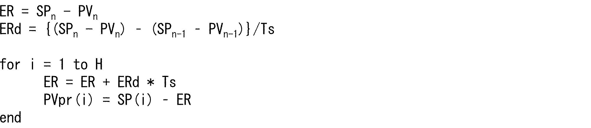
を実行する。
すなわち、第2予測部530は、「現在の主軸側制御周期における主軸指令位置(上述の式におけるSPn)」と「現在の主軸側制御周期におけるFB位置(主軸)(上述の式におけるPVn)」との差から、「現在の主軸側制御周期における位置偏差(ERn)」を算出する。
また、第2予測部530は、「現在から1周期前の主軸側制御周期における主軸指令位置(上述の式におけるSPn-1)」と「現在から1周期前の主軸側制御周期におけるFB位置(主軸)(上述の式におけるPVn-1)」との差から、「現在から1周期前の主軸側制御周期における位置偏差(ERn-1)」を算出する。
そして、第2予測部530は、「現在の主軸側制御周期における位置偏差(ERn)」と、「現在から1周期前の主軸側制御周期における位置偏差(ERn-1)」との差を、主軸側制御周期の時間間隔である周期時間Tsで除して、「現在の主軸側制御周期における、位置偏差の時間に対する変化(率)」を示す、「現在の主軸側制御周期における位置偏差変化率(上述の式におけるERd)」を算出する。
第2予測部530は、算出した「現在の主軸側制御周期における位置偏差変化率ERd」が、未来の主軸側制御周期においても一定で継続すると仮定して、「未来の主軸側制御周期における位置偏差(ERi)」を算出する。具体的には、「未来の主軸側制御周期における位置偏差(ERi)」が、「i周期後の位置偏差(「i=1 to H」とする)」であるとして、第2予測部530は、「i周期後の位置偏差(ERi)」を、上述の式の通り予測する。すなわち、第2予測部530は、周期時間Ts、「現在の主軸側制御周期における位置偏差変化率(ERd)」、および、「現在の主軸側制御周期における位置偏差(ERn)」から、「ERi=ERn+ERd*Ts*i」を演算する。
そして、第2予測部530は、「i周期後の主軸側制御周期における主軸指令位置(上述の式におけるSPi)」と、演算した「i周期後の位置偏差(ERi)」との差から、「i周期後の主軸側制御周期におけるFB位置(主軸)(上述の式におけるPVpr(i))」を予測する。
第2予測部530は、予測した主軸側制御周期ごとの「未来の主軸側制御周期におけるFB位置(主軸)」を、カム演算部540に通知し、また、記憶部570の予測主軸位置テーブル571に格納する。
カム演算部540は、第2予測部530から通知された「未来の主軸側制御周期におけるFB位置(主軸)」に対応する、「未来の従軸制御周期における指令位置(従軸)」を演算する。なお、以下では、カム演算部540が「未来の主軸側制御周期におけるFB位置(主軸)」から演算する「未来の従軸制御周期における指令位置(従軸)」を、「対応従属位置」とも称する。
カム演算部540は、例えば、「主軸の位置に対して、従軸の位置を対応付けた配列」である主従関係情報(例えば、いわゆる「カムテーブル」)を用いて、対応従属位置を演算する。カム演算部540は、「主軸の位置に対して、従軸の位置を対応付けた演算式(例えば、いわゆる「カム演算式」)」を用いて、対応従属位置を演算してもよい。カム演算部540は、周知の技術を用いて、対応従属位置を演算できればよく、対応従属位置を演算する方法は、特に限定されない。
カム演算部540は、「未来の主軸側制御周期におけるFB位置(主軸)」から演算した、「未来の主軸側制御周期におけるFB位置(主軸)」に対応する「未来の従軸制御周期における指令位置(従軸)」を、第2MPC部550に通知する。
第2MPC部550は、従軸サーボ系700の動特性モデルを用いて、従軸サーボ系700についてMPC(モデル予測制御)を行なう。具体的には、第2MPC部550は、カム演算部540により演算された対応従属位置と、従軸サーボ系700から取得するFB位置(従軸)とを用いて、従軸サーボ系700の動特性モデルを用いたMPCによって、指令速度(従軸)を生成する。
先ず、第2MPC部550は、従軸サーボドライバ710および機械730のモデル(つまり、従軸サーボ系700の動特性モデル)を内部モデルとして有し、この内部モデルを用いて、「未来の周期(従軸側制御周期)におけるFB位置(従軸)」を予測する。例えば、第2MPC部550は、従軸サーボ系700の動特性モデルによって、「これまでに取得しているFB位置(従軸)」および「これまでに従軸サーボドライバ710へ出力している指令値(従軸)」を用いて、「未来の従軸側制御周期におけるFB位置(従軸)」を予測する。
そして、第2MPC部550は、予測した「未来の周期におけるFB位置(従軸)」が、カム演算部540により演算された対応従属位置に一致するように、従軸サーボ系700に対する現在の周期における指令値(例えば、指令速度(従軸))を生成する。第2MPC部550は、予測した「未来の周期におけるFB位置(従軸)」が、「未来の主軸側制御周期におけるFB位置(主軸)」に対応する「未来の従軸制御周期における指令位置(従軸)」に一致するよう、現在の従軸制御周期における指令速度(従軸)を生成する。第2MPC部550は、生成した「現在の従軸制御周期における指令速度(従軸)」を、現在の従軸制御周期において、従軸サーボ系700(具体的には、従軸サーボドライバ710)に出力する。
監視部560は、監視部150と同様であるため、詳細は略記する。また、記憶部570、および、記憶部570に格納されている予測主軸位置テーブル571は、各々、記憶部160、および記憶部160に格納されている予測主軸位置テーブル161と同様であるため、詳細は略記する。すなわち、予測主軸位置テーブル571には、第2予測部530によって、第2予測部530が各主軸側制御周期において予測した、主軸側制御周期ごとの「未来の主軸側制御周期におけるFB位置(主軸)」が格納される。また、監視部560は、第2予測部530により予測された「未来の主軸側制御周期におけるFB位置(主軸)」を監視し、例えば、予測主軸位置テーブル571に格納されている複数周期分の「未来の主軸側制御周期におけるFB位置(主軸)」を監視する。監視部560は、「未来の主軸側制御周期におけるFB位置(主軸)」の経時変化を監視することによって、「未来の主軸側制御周期におけるFB位置(主軸)」の変動を検知し、例えば、変動にみられる傾向性および急激な変動の発生等を把握する。
(コントローラが実行する処理について)
図4は、コントローラ500が実行する処理の全体概要を示すフロー図である。コントローラ500は先ず初期処理を実行し(S810)、例えば、起動後、通常動作(主軸サーボ系600および従軸サーボ系700の各々への制御処理)を開始する前の初期イニシャライズ(初期処理、例えば、通常動作に必要な各種の設定処理等)を実行する。
図4は、コントローラ500が実行する処理の全体概要を示すフロー図である。コントローラ500は先ず初期処理を実行し(S810)、例えば、起動後、通常動作(主軸サーボ系600および従軸サーボ系700の各々への制御処理)を開始する前の初期イニシャライズ(初期処理、例えば、通常動作に必要な各種の設定処理等)を実行する。
コントローラ500は、主軸サーボ系600および従軸サーボ系700の各々から、主軸および従軸の各々のFB値(つまり、FB位置(主軸)およびFB位置(従軸))を入力として受け付ける(S820)。そして、指令値生成部510は、主軸の目標軌道データから、主軸側制御周期ごとの主軸サーボドライバ610への指令値(例、指令位置(主軸))を計算する(S830)。指令値生成部510は、生成した指令位置(主軸)を、第1MPC部520および第2予測部530へと出力する。指令値生成部510から指令位置(主軸)を通知された第1MPC部520は、主軸サーボ系600の動特性モデルを用いるMPCによって、主軸サーボドライバ610に対する指令値(例、指令速度(主軸))を計算する(S840)。
第2予測部530は、S820で受け付けたFB位置(主軸)と、指令値生成部510から取得する「過去、現在、および、未来の主軸側制御周期の各々における指令位置(主軸)」とから、主軸の未来のFB値を予測する(S850)。すなわち、第2予測部530は、過去および現在の主軸側制御周期の各々における位置偏差(=指令位置とFB位置との偏差)と、未来の主軸側制御周期における指令位置(主軸)とを用いて、未来の主軸側制御周期におけるFB位置(主軸)を、予測する。第2予測部530は、予測した「未来の主軸側制御周期におけるFB位置(主軸)」を、カム演算部540に通知する。
カム演算部540は、第2予測部530から通知された「未来の主軸側制御周期におけるFB位置(主軸)」に対応する、従軸の未来対応値(対応従属位置)を、つまり、「未来の従軸制御周期における指令位置(従軸)」を、計算する(S860)。カム演算部540は、「未来の主軸側制御周期におけるFB位置(主軸)」から計算した対応従属位置を、第2MPC部550に通知する。
第2MPC部550は、従軸サーボ系700の動特性モデルを用いて、従軸サーボドライバ710への指令値を計算し(S870)、つまり、従軸サーボ系700の動特性モデルを用いたMPCを従軸サーボ系700の制御に適用する。具体的には、第2MPC部550は、従軸サーボ系700の動特性モデルを用いて予測した「未来の周期(従軸側制御周期)におけるFB位置(従軸)」が、S860で計算した対応従属位置に一致するように、指令速度(従軸)を生成する。
コントローラ500(具体的には、第1MPC部520および第2MPC部550の各々)は、主軸側および従軸側のサーボドライバ(つまり、主軸サーボドライバ610および従軸サーボドライバ710)へ、指令値を出力する(S880)。すなわち、第1MPC部520は主軸サーボドライバ610に指令速度(主軸)を出力し、第2MPC部550は従軸サーボドライバ710に指令速度(従軸)を出力する。そして、コントローラ500は、制御が終了する(S890でYes)まで、S820からS880までの処理を、制御周期ごとに繰り返す。
これまでに図4を用いて説明してきた、コントローラ500の実行する制御方法は、以下のように整理することができる。すなわち、コントローラ500の実行する制御方法は、主軸の位置に対して従軸の位置を追従させる制御装置の制御方法であって、「主軸の目標軌道から生成される指令位置である指令位置(主軸)(つまり、主軸指令位置)と、FB位置(主軸)との偏差である位置偏差(つまり、位置偏差(主軸))」の、現在における時間変化率が、所定期間にわたって一定のまま継続すると仮定して、未来におけるFB位置(主軸)を予測する予測ステップ(S850)と、予測ステップにて予測された「未来におけるFB位置(主軸)」に対応する、「未来における従軸の位置」である対応従属位置を演算する演算ステップ(S860)と、従軸の位置をフィードバック制御する従軸サーボ系700の動特性モデルを用いて予測する「未来における従軸の予測位置」が、演算ステップにて演算された「未来における対応従属位置」に一致するように、従軸サーボ系700に対する現在における指令値である従軸指令値を生成する従軸指令ステップ(S870)と、を含んでいる。
前記の方法によれば、前記制御方法は、「位置偏差(主軸)の、現在における時間変化率が、所定期間にわたって一定のまま継続する」と仮定して、未来におけるFB位置(主軸)を予測する。
特に、前記制御方法は、主軸サーボ系600の動特性モデルを用いずに予測した「未来のFB位置(主軸)」から、「未来のFB位置(主軸)」に対応する、「従軸の未来の位置」である対応従属位置を演算する。そして、前記制御方法は、演算した「対応従属位置(未来における従軸の位置)」を「従軸の未来の指令値(指令位置)」とする、従軸サーボ系700の動特性モデルを用いたMPCを、従軸の制御に適用する。つまり、前記制御方法は、未来におけるFB位置(主軸)を予測し、予測した「未来におけるFB位置(主軸)」に対応する「対応従属位置(従軸の未来の指令値、未来の周期における指令位置(従軸))」を用いたMPCを、従軸の制御に適用する。
したがって、前記制御方法は、従軸の位置制御について追従性を向上させ、従軸の位置制御を高速化・高精度化することができるとの効果を奏する。例えば、前記制御方法は、前記制御方法によって制御する機械等の動作をより高速化させて、これらの機械を用いた生産現場の生産性の向上に寄与するとの効果を奏する。
〔実施形態3〕
本発明の実施形態3について、図5に基づいて、以下に説明する。なお、説明の便宜上、前記実施形態にて説明した部材と同じ機能を有する部材については、同じ符号を付記し、その説明を省略する。
本発明の実施形態3について、図5に基づいて、以下に説明する。なお、説明の便宜上、前記実施形態にて説明した部材と同じ機能を有する部材については、同じ符号を付記し、その説明を省略する。
図5は、実施形態3に係るコントローラ900等の要部構成を示すブロック図である。図5に示すように、コントローラ900は、実施形態2に係るコントローラ500と以下の1点において異なり、他の点においてはコントローラ500と同様である。すなわち、コントローラ900は、コントローラ500の第2予測部530に代えて、コントローラ100の第1予測部120を備え、その他の構成はコントローラ500と同様である。
ここで、コントローラ100の第1予測部120およびコントローラ500の各構成については既に説明しているから、詳細は略記する。すなわち、コントローラ900の第1予測部120は、主軸サーボ系600から、「主軸サーボ系600(特に、機械630)の出力である主軸の位置(=FB位置(主軸))」を、FB情報として、主軸側制御周期ごとに取得する。そして、第1予測部120は、主軸側制御周期ごとに取得したFB位置(主軸)から、「未来の主軸側制御周期におけるFB位置(主軸)」を主軸側制御周期ごとに予測する。第1予測部120は、予測した主軸側制御周期ごとの「未来の主軸側制御周期におけるFB位置(主軸)」を、カム演算部540に通知し、また、記憶部570の予測主軸位置テーブル571に格納する。カム演算部540は、第1予測部120から通知された「未来の主軸側制御周期におけるFB位置(主軸)」に対応する、「未来の従軸制御周期における指令位置(従軸)」を演算する。
「第2予測部530に代えて、第1予測部120を備えている」点を除いて、コントローラ900がコントローラ500と同様であるのに対応して、コントローラ900が実行する処理も、コントローラ500の実行する処理とほぼ同様である。
具体的には、図4のS850において、第2予測部530は、S820で受け付けたFB位置(主軸)と、指令値生成部510から取得する「過去、現在、および、未来の主軸側制御周期の各々における指令位置(主軸)」とから、主軸の未来のFB値を予測した。これに対して、コントローラ900は、図4のS810からS840までの処理を実行した後、以下の処理を実行する。
すなわち、コントローラ900の第1予測部120は、S820で受け付けたFB位置(主軸)から、主軸の未来FB値を、つまり、「未来の主軸側制御周期におけるFB位置(主軸)」を、予測する(S850’)。そして、第1予測部120は、予測した「未来の主軸側制御周期におけるFB位置(主軸)」を、カム演算部540に通知する。その後、コントローラ900は、図4のS860からS890までの処理を実行する。
〔各実施形態のコントローラが奏する効果〕
これまでに説明してきたコントローラ100、500、および900の各々が奏する効果について、以下に図6から図9を用いて説明していく。具体的には、主軸制御に外乱を印加するシミュレーション1およびシミュレーション2の各々において、従来のコントローラおよび各実施形態に係るコントローラが実現する従軸制御について、以下に詳細を説明していく。
これまでに説明してきたコントローラ100、500、および900の各々が奏する効果について、以下に図6から図9を用いて説明していく。具体的には、主軸制御に外乱を印加するシミュレーション1およびシミュレーション2の各々において、従来のコントローラおよび各実施形態に係るコントローラが実現する従軸制御について、以下に詳細を説明していく。
(シミュレーション例1)
図6は、シミュレーション1において、主軸の制御(例えば、制御システム1における主軸サーボ系200、制御システム2における主軸サーボ系600、および、制御システム3における主軸サーボ系600)に印加する正弦波状のトルク外乱を示す図である。図6に例示するように、以下に説明するシミュレーション1において、主軸の制御に印加する外乱は、振幅50%、周波数10Hzの正弦波状のトルク外乱とする。
図6は、シミュレーション1において、主軸の制御(例えば、制御システム1における主軸サーボ系200、制御システム2における主軸サーボ系600、および、制御システム3における主軸サーボ系600)に印加する正弦波状のトルク外乱を示す図である。図6に例示するように、以下に説明するシミュレーション1において、主軸の制御に印加する外乱は、振幅50%、周波数10Hzの正弦波状のトルク外乱とする。
図7は、図6の外乱を印加した場合に、従来のコントローラおよび各実施形態に係るコントローラ(つまり、コントローラ100、500、および900)が実現する従軸制御について説明する図である。シミュレーション1において、従来のコントローラおよび各実施形態に係るコントローラは、主軸と従軸とに同一の動作をさせようとするものとし、図6に示す外乱を主軸の制御に印加したときの、各コントローラの従軸制御の結果を示すのが、図7である。
図7において(A)は、従来のコントローラ(つまり、「主軸の未来のフィードバック値」の予測を行なわないコントローラ)について、主軸の制御に図6の外乱を印加した場合の「指令位置」、「位置偏差」、および、「トルク」を順に示している。なお、従来のコントローラは、従軸の制御において、現在の指令値が予測区間継続するとみなして従軸の制御を行なうものとする。
同様に、図7において(B)は、コントローラ100について、主軸サーボ系200に図6の外乱を印加した場合の「指令位置」、「位置偏差」、および、「トルク」を順に示している。図7において(C)は、コントローラ900について、主軸サーボ系600に図6の外乱を印加した場合の「指令位置」、「位置偏差」、および、「トルク」を順に示している。図7において(D)は、コントローラ500について、主軸サーボ系200に図6の外乱を印加した場合の「指令位置」、「位置偏差」、および、「トルク」を順に示している。
ここで、図7の(A)から(D)の各々における「指令位置」は、従軸側への指令位置を示しており、具体的には主軸のFB位置(つまり、FB位置(主軸))を示している。また、図7の(A)から(D)の各々における「位置偏差」は、主軸のFB位置(つまり、FB位置(主軸)。言い換えれば、前述の従軸側への「指令位置」)と従軸のFB位置(つまり、FB位置(従軸))との偏差を示している。さらに、図7の(A)から(D)の各々における「トルク」は、従軸を制御するフィードバック制御系(例えば、従軸サーボ系300または従軸サーボ系700)の出力するトルクを示している。
なお、前述の通り、主軸サーボ系600の動特性モデルを用いたMPCを主軸サーボ系600の制御に適用するコントローラ500および900は、主軸サーボ系600の制御について動摩擦補償も適用するものとする。これに対して、コントローラ100は、主軸サーボ系200の制御にMPCも動摩擦補償も適用していない。
図7に示すように、従来のコントローラ(図7の(A)に対応)と比較して、コントローラ100、500、および900(各々、図7の(B)、(D)、および(C)に対応)はいずれも、追従性が大幅に向上している。具体的には、図7の(A)の「位置偏差」に比べて、図7の(B)、(D)、および(C)の各々における「位置偏差」は大幅に低減している。これは、未来のFB位置(主軸)の予測が、つまり、従軸側への未来の「指令位置」の予測が、従軸の制御に対して大きな効果を果たすことを示している。
ここで、時刻0sの「動作開始時」、および、動作開始から0.25s後、0.5s後、0.75s後における「動作方向反転時」は、摩擦の影響によって「位置偏差」が大きくなりやすい。図7の(A)においては「位置偏差」が全体的に大きく、グラフのレンジが大きいために確認できないが、図7の(B)、(D)、および(C)の各々において、「動作開始時」および「動作方向反転時」に、「位置偏差」が大きくなっていることが分かる。これは、「動作反転時(および動作開始時)」は、摩擦によって加速度が不連続に変化するため、予測値(つまり、「未来のFB位置(主軸)」。本シミュレーションでは、従軸側への未来の「指令位置」と一致)と実測値との誤差が大きくなることが原因である。
例えば、図7の(B)(コントローラ100に対応)と比べて、図7の(C)(コントローラ900に対応)において、「動作反転時(および動作開始時)」の「位置偏差」は抑制されている。これは、コントローラ900が主軸制御に動摩擦補償を適用しているために、主軸のFB値(具体的には、FB位置(主軸))の加速度変化が低減されているためである。
また、図7の(C)(コントローラ900に対応)と比べて、図7の(D)(コントローラ500に対応)において、「動作反転時(および動作開始時)」の「位置偏差」はさらに抑制されている。これは、予測値(つまり、「未来のFB位置(主軸)」。本シミュレーションでは、従軸側への未来の「指令位置」と一致)の予測方法におけるコントローラ900とコントローラ500との違いが影響しているものと考えられる。
つまり、未来のFB位置(主軸)(=従軸側への未来の「指令位置」)の予測に、FB位置(主軸)の加速度情報を用いるか、または、主軸の位置偏差(つまり、FB位置(主軸)と指令位置(主軸)との偏差)の変化率を用いるかの違いが主因と考えられる。
前述の通り、コントローラ900は、未来のFB位置(主軸)(=従軸側への未来の「指令位置」)の予測に、主軸のFB位置の加速度情報を用い、主軸の位置偏差の変化率を用いていない。コントローラ900は、コントローラ500の第2予測部530に代えて、コントローラ100の第1予測部120を備える。そして、コントローラ900の第1予測部120は、未来の主軸側制御周期におけるFB位置(主軸)の予測に、「現在および過去の各々の主軸側制御周期におけるFB位置(主軸)」を利用し、「主軸の位置偏差の変化率」を利用しない。
これに対して、コントローラ500の第2予測部530は、主軸の各主軸側制御周期における位置偏差の、時間に対する変化率が、複数の周期にわたって一定であると仮定して、未来の主軸側制御周期におけるFB位置(主軸)を予測する。
つまり、コントローラ900が未来のFB位置(主軸)の予測に「主軸の位置偏差の変化率」を用いないのに対し、コントローラ500は「主軸の位置偏差の変化率」を用いて未来のFB位置(主軸)を予測する。未来のFB位置(主軸)の予測方法についての、コントローラ500とコントローラ900との違いから、「動作反転時(および動作開始時)」の「位置偏差」は、図7の(C)に比べて図7の(D)において、より抑制されているものと考えられる。
さらに、図7の(D)(コントローラ500に対応)の「トルク」は、図7の(B)および図7の(C)の各々における「トルク」に比べて、ピーク値が抑制されていることが分かる。
(シミュレーション例2)
図8は、シミュレーション2において、主軸の制御(例えば、制御システム1における主軸サーボ系200、制御システム2における主軸サーボ系600、および、制御システム3における主軸サーボ系600)に印加するパルス状のトルク外乱を示す図である。図8に例示するように、以下に説明するシミュレーション2においては、時刻0.3sに、大きさ200%、時間幅50msのパルス状のトルク外乱を主軸の制御に印加するものとする。
図8は、シミュレーション2において、主軸の制御(例えば、制御システム1における主軸サーボ系200、制御システム2における主軸サーボ系600、および、制御システム3における主軸サーボ系600)に印加するパルス状のトルク外乱を示す図である。図8に例示するように、以下に説明するシミュレーション2においては、時刻0.3sに、大きさ200%、時間幅50msのパルス状のトルク外乱を主軸の制御に印加するものとする。
図9は、図8の外乱を印加した場合に、従来のコントローラおよび各実施形態に係るコントローラ(つまり、コントローラ100、500、および900)が実現する従軸制御について説明する図である。シミュレーション2において、従来のコントローラおよび各実施形態に係るコントローラは、シミュレーション1と同様に、主軸と従軸とに同一の動作をさせようとするものとする。シミュレーション2において、図8に示す外乱を主軸の制御に印加したときの、各コントローラの従軸制御の結果を示すのが、図9である。
図9において(A)は、従来のコントローラ(つまり、「主軸の未来のフィードバック値」の予測を行なわないコントローラ)について、主軸の制御に図8の外乱を印加した場合の「指令位置」、「位置偏差」、および、「トルク」を順に示している。なお、従来のコントローラは、従軸の制御において、現在の指令値が予測区間継続するとみなして従軸の制御を行なうものとする。
同様に、図9において(B)は、コントローラ100について、主軸サーボ系200に図8の外乱を印加した場合の「指令位置」、「位置偏差」、および、「トルク」を順に示している。図9において(C)は、コントローラ900について、主軸サーボ系600に図8の外乱を印加した場合の「指令位置」、「位置偏差」、および、「トルク」を順に示している。図9において(D)は、コントローラ500について、主軸サーボ系200に図8の外乱を印加した場合の「指令位置」、「位置偏差」、および、「トルク」を順に示している。
ここで、図9の(A)から(D)の各々における「指令位置」は、従軸側への指令位置を示しており、具体的には主軸のFB位置(つまり、FB位置(主軸))を示している。また、図9の(A)から(D)の各々における「位置偏差」は、主軸のFB位置(つまり、FB位置(主軸)。言い換えれば、前述の従軸側への「指令位置」)と従軸のFB位置(つまり、FB位置(従軸))との偏差を示している。さらに、図9の(A)から(D)の各々における「トルク」は、従軸を制御するフィードバック制御系(例えば、従軸サーボ系300または従軸サーボ系700)の出力するトルクを示している。
なお、前述の通り、主軸サーボ系600の動特性モデルを用いたMPCを主軸サーボ系600の制御に適用するコントローラ500および900は、主軸サーボ系600の制御について動摩擦補償も適用するものとする。これに対して、コントローラ100は、主軸サーボ系200の制御にMPCも動摩擦補償も適用していない。
図9に示すように、従来のコントローラ(図9の(A)に対応)と比較して、コントローラ100、500、および900(各々、図9の(B)、(D)、および(C)に対応)はいずれも、追従性が大幅に向上している。具体的には、図9の(A)の「位置偏差」に比べて、図9の(B)、(D)、および(C)の各々における「位置偏差」は大幅に低減している。これは、未来のFB位置(主軸)の予測が、つまり、従軸側への未来の「指令位置」の予測が、従軸の制御に対して大きな効果を果たすことを示している。
ここで、時刻0.3sの「外乱印加開始時」と、時刻0.35sの「外乱印加終了時」とにおいて、図9の(B)、(D)、および(C)の各々における「位置偏差」は大きくなっている。なお実際には、図9の(A)においても、「外乱印加開始時」と「外乱印加終了時」とにおいて「位置偏差」は大きくなっているが、図9の(A)においては「位置偏差」が全体的に大きいために、目立たないだけである。
図9の(B)、(D)、および(C)の各々における「位置偏差」は、ほぼ等しい大きさである。ただし、図9の(D)(コントローラ500に対応)の「トルク」は、図9の(B)(コントローラ100に対応)および図9の(C)(コントローラ900に対応)の各々における「トルク」に比べて、ピーク値が抑制されている。この違いは、コントローラ500と、コントローラ100および900との、未来のFB位置(主軸)(=従軸側への未来の「指令位置」)の予測方法の違いに起因するものと考えられる。
すなわち、コントローラ500は、主軸の位置偏差の変化率(つまり、主軸のFB位置の速度情報)を用いて、未来のFB位置(主軸)(=従軸側への未来の「指令位置」)を予測している。これに対して、コントローラ100および900は、未来のFB位置(主軸)の予測に、FB位置(主軸)の加速度を用いて、主軸の位置偏差の変化率を用いない。
§4.変形例
これまで、コントローラ100、500、および900の各々が、従軸サーボドライバ310および従軸サーボドライバ710の各々に、指令速度(従軸)を送信する例を説明した。しかしながら、コントローラ100、500、および900の各々は、従軸サーボドライバ310および従軸サーボドライバ710の各々に、「従軸についての指令位置(つまり、指令位置(従軸))」を送信してもよい。この場合、従軸サーボドライバ310および従軸サーボドライバ710の各々について、速度制御部320および速度制御部720の各々が実行する速度制御ループの前に、位置制御ループが追加されることになる。
これまで、コントローラ100、500、および900の各々が、従軸サーボドライバ310および従軸サーボドライバ710の各々に、指令速度(従軸)を送信する例を説明した。しかしながら、コントローラ100、500、および900の各々は、従軸サーボドライバ310および従軸サーボドライバ710の各々に、「従軸についての指令位置(つまり、指令位置(従軸))」を送信してもよい。この場合、従軸サーボドライバ310および従軸サーボドライバ710の各々について、速度制御部320および速度制御部720の各々が実行する速度制御ループの前に、位置制御ループが追加されることになる。
同様に、コントローラ500は、主軸サーボドライバ610に、「主軸についての指令位置(つまり、指令位置(主軸))」を送信してもよい。この場合、主軸サーボドライバ610について、速度制御部620が実行する速度制御ループの前に、位置制御ループが追加されることになる。
また、これまで、コントローラ100、500、および900の各々が、電子カム制御に適用される例を説明してきたが、コントローラ100、500、および900の各々の適用範囲は、電子カム制御に限られるものではない。コントローラ100、500、および900の各々の適用範囲は、主軸の位置に対して従軸の位置を追従させる制御であれば、特に限定されない。
〔ソフトウェアによる実現例〕
コントローラ100、500、および900の制御ブロック(特に、指令値生成部110、第1予測部120、カム演算部130、MPC部140、監視部150、指令値生成部510、第1MPC部520、第2予測部530、カム演算部540、第2MPC部550、および、監視部560)は、集積回路(ICチップ)等に形成された論理回路(ハードウェア)によって実現してもよいし、ソフトウェアによって実現してもよい。
コントローラ100、500、および900の制御ブロック(特に、指令値生成部110、第1予測部120、カム演算部130、MPC部140、監視部150、指令値生成部510、第1MPC部520、第2予測部530、カム演算部540、第2MPC部550、および、監視部560)は、集積回路(ICチップ)等に形成された論理回路(ハードウェア)によって実現してもよいし、ソフトウェアによって実現してもよい。
後者の場合、コントローラ100、500、および900は、各機能を実現するソフトウェアであるプログラムの命令を実行するコンピュータを備えている。このコンピュータは、例えば1つ以上のプロセッサを備えていると共に、上記プログラムを記憶したコンピュータ読み取り可能な記録媒体を備えている。そして、上記コンピュータにおいて、上記プロセッサが上記プログラムを上記記録媒体から読み取って実行することにより、本発明の目的が達成される。上記プロセッサとしては、例えばCPU(Central Processing Unit)を用いることができる。上記記録媒体としては、「一時的でない有形の媒体」、例えば、ROM(Read Only Memory)等の他、テープ、ディスク、カード、半導体メモリ、プログラマブルな論理回路などを用いることができる。また、上記プログラムを展開するRAM(Random Access Memory)などをさらに備えていてもよい。また、上記プログラムは、該プログラムを伝送可能な任意の伝送媒体(通信ネットワークや放送波等)を介して上記コンピュータに供給されてもよい。なお、本発明の一態様は、上記プログラムが電子的な伝送によって具現化された、搬送波に埋め込まれたデータ信号の形態でも実現され得る。
(付記事項)
本発明の一態様に係る制御装置は、主軸の位置に対して従軸の位置を追従させる制御装置であって、(A)前記主軸の位置をフィードバック制御する第1サーボ制御系の、前記主軸のフィードバック位置である主軸フィードバック位置の現在における加速度が、所定期間にわたって一定のまま継続すると仮定して、または、(B)前記主軸の目標軌道から生成される指令位置である主軸指令位置と前記主軸フィードバック位置との偏差である位置偏差の、現在における時間変化率が、所定期間にわたって一定のまま継続すると仮定して、未来における前記主軸フィードバック位置を予測する予測部と、前記予測部により予測された未来における前記主軸フィードバック位置に対応する、前記従軸の位置である対応従属位置を演算する演算部と、前記従軸の位置をフィードバック制御する第2サーボ制御系の動特性モデルを用いて予測する、未来における前記従軸の予測位置が、前記演算部により演算された前記対応従属位置に一致するように、前記第2サーボ制御系に対する現在における指令値である従軸指令値を生成する従軸指令部と、を備えている。
本発明の一態様に係る制御装置は、主軸の位置に対して従軸の位置を追従させる制御装置であって、(A)前記主軸の位置をフィードバック制御する第1サーボ制御系の、前記主軸のフィードバック位置である主軸フィードバック位置の現在における加速度が、所定期間にわたって一定のまま継続すると仮定して、または、(B)前記主軸の目標軌道から生成される指令位置である主軸指令位置と前記主軸フィードバック位置との偏差である位置偏差の、現在における時間変化率が、所定期間にわたって一定のまま継続すると仮定して、未来における前記主軸フィードバック位置を予測する予測部と、前記予測部により予測された未来における前記主軸フィードバック位置に対応する、前記従軸の位置である対応従属位置を演算する演算部と、前記従軸の位置をフィードバック制御する第2サーボ制御系の動特性モデルを用いて予測する、未来における前記従軸の予測位置が、前記演算部により演算された前記対応従属位置に一致するように、前記第2サーボ制御系に対する現在における指令値である従軸指令値を生成する従軸指令部と、を備えている。
前記の構成によれば、前記制御装置は、未来における前記主軸フィードバック位置を、(1)前記主軸フィードバック位置の現在における加速度が所定期間にわたって一定のまま継続すると仮定して、または、(2)前記位置偏差の、現在における時間変化率が、所定期間にわたって一定のまま継続すると仮定して、予測する。
特に、前記制御装置は、前記第1サーボ制御系の動特性モデルを用いずに予測した前記主軸の未来のフィードバック位置から、前記主軸の未来のフィードバック位置に対応する、前記従軸の未来の位置である対応従属位置を演算する。そして、前記制御装置は、演算した前記対応従属位置を前記従軸の未来の指令値(指令位置)とする、前記第2サーボ制御系の動特性モデルを用いたモデル予測制御を、前記従軸の制御に適用する。つまり、前記制御装置は、未来における前記主軸フィードバック位置を予測し、予測した「未来における前記主軸フィードバック位置」に対応する「前記従軸の未来の指令値」を用いたモデル予測制御を、前記従軸の制御に適用する。
したがって、前記制御装置は、前記従軸の位置制御について追従性を向上させ、前記従軸の位置制御を高速化・高精度化することができるとの効果を奏する。例えば、前記制御装置は、前記制御装置によって制御する機械等の動作をより高速化させて、これらの機械を用いた生産現場の生産性の向上に寄与するとの効果を奏する。
本発明の一態様に係る制御装置は、前記主軸の位置に対して前記従軸の位置を追従させ、前記予測部は、各周期における前記主軸フィードバック位置の加速度が、複数の周期にわたって一定であると仮定して、現在および過去の各周期における前記主軸フィードバック位置を用いて、未来の周期における前記主軸フィードバック位置を予測してもよい。
前記の構成によれば、前記制御装置は、現在および過去の各周期における前記主軸フィードバック位置を用いて、未来の周期における前記主軸フィードバック位置を予測する。
例えば、前記制御装置は、現在の周期における前記主軸フィードバック位置と、現在から1周期前の周期における前記主軸フィードバック位置との差を、前記周期の時間間隔である周期時間で除して、現在の周期における前記第1サーボ制御系のフィードバック速度を算出する。
また、前記制御装置は、現在から1周期前の周期における前記主軸フィードバック位置と、現在から2周期前の周期における前記主軸フィードバック位置との差を、前記周期時間で除して、現在から1周期前の周期における前記第1サーボ制御系のフィードバック速度を算出する。
そして、前記制御装置は、前記第1サーボ制御系の現在の周期におけるフィードバック速度と、現在から1周期前の周期におけるフィードバック速度との差を、前記周期時間で除して、現在の周期における前記第1サーボ制御系のフィードバック加速度を算出する。
前記制御装置は、算出した「現在の周期における前記第1サーボ制御系のフィードバック加速度」が未来の周期においても一定で継続すると仮定して、前記周期時間、「前記第1サーボ制御系の現在の周期におけるフィードバック加速度」、「前記第1サーボ制御系の現在の周期におけるフィードバック速度」、および、「前記第1サーボ制御系の現在の周期における前記主軸フィードバック位置」から、未来の周期における前記主軸フィードバック位置を予測する。
そして、前記制御装置は、予測した「未来の周期における前記主軸フィードバック位置」に対応する、前記従軸の未来の位置である対応従属位置を演算する。前記制御装置は、演算した前記対応従属位置を前記従軸の未来の指令値(指令位置)とする、前記第2サーボ制御系の動特性モデルを用いたモデル予測制御を、前記従軸の制御に適用する。つまり、前記制御装置は、前記従軸の制御に適用する前記モデル予測制御に、現在および過去の前記主軸フィードバック位置を用いて予測した「未来の前記主軸フィードバック位置」に対応する、前記従軸の未来の指令値(前記対応従属位置)を用いる。
したがって、前記制御装置は、主軸の位置に対して従軸の位置を追従させる制御装置において、前記従軸の位置制御について追従性を向上させ、前記従軸の位置制御を高速化・高精度化することができるとの効果を奏する。
本発明の一態様に係る制御装置は、前記主軸の位置に対して前記従軸の位置を追従させ、前記予測部は、各周期における前記主軸指令位置と前記主軸フィードバック位置との偏差である前記位置偏差の、時間に対する変化率が、複数の周期にわたって一定であると仮定して、(C)現在および過去の各周期における前記主軸フィードバック位置と、(D)過去、現在、および、未来の各周期における前記主軸指令位置と、を用いて、未来の周期における前記主軸フィードバック位置を予測してもよい。
前記の構成によれば、前記制御装置は、(C)現在および過去の各周期における前記主軸フィードバック位置と、(D)過去、現在、および、未来の各周期における前記主軸指令位置と、を用いて、未来の周期における前記主軸フィードバック位置を予測する。
例えば、前記制御装置は、現在の周期における前記主軸指令位置と前記主軸フィードバック位置との差から、現在の周期における前記位置偏差を算出する。また、前記制御装置は、現在から1周期前の周期における前記主軸指令位置と前記主軸フィードバック位置との差から、現在から1周期前の周期における前記位置偏差を算出する。
そして、前記制御装置は、現在の周期における前記位置偏差と、現在から1周期前の周期における位置偏差との差を、前記周期の時間間隔である周期時間で除して、「現在の周期における、前記位置偏差の時間に対する変化(率)」を示す、「現在の周期における位置偏差変化率」を算出する。
前記制御装置は、算出した「現在の周期における位置偏差変化率」が未来の周期においても一定で継続すると仮定して、前記周期時間、「現在の周期における位置偏差変化率」、および、「現在の周期における位置偏差」から、「未来の周期における前記位置偏差」を算出する。
そして、前記制御装置は、「未来の周期における主軸指令位置」と、算出した「未来の周期における前記位置偏差」との差から、「未来の周期における前記主軸フィードバック位置」を予測する。
前記制御装置は、予測した「未来の周期における前記主軸フィードバック位置」に対応する、前記従軸の未来の位置である対応従属位置を演算する。前記制御装置は、演算した前記対応従属位置を前記従軸の未来の指令値(指令位置)とする、前記第2サーボ制御系の動特性モデルを用いたモデル予測制御を、前記従軸の制御に適用する。つまり、前記制御装置は、前記従軸の制御に適用する前記モデル予測制御に、「現在および過去の前記主軸フィードバック位置」と、「過去、現在、および、未来の前記主軸指令位置」とを用いて予測した「未来の前記主軸フィードバック位置」に対応する、前記従軸の未来の指令値(前記対応従属位置)を用いる。
したがって、前記制御装置は、主軸の位置に対して従軸の位置を追従させる制御装置において、前記従軸の位置制御について追従性を向上させ、前記従軸の位置制御を高速化・高精度化することができるとの効果を奏する。
本発明の一態様に係る制御装置は、前記第1サーボ制御系の動特性モデルを用いて予測する未来における前記主軸の予測位置が、未来における前記主軸指令位置に一致するように、前記第1サーボ制御系に対する現在における指令値である指令主軸値を生成する主軸指令部をさらに備えてもよい。
前記の構成によれば、前記制御装置は、前記第1サーボ制御系の動特性モデルを用いて予測する未来における前記主軸の予測位置が、未来における前記主軸指令位置に一致するように、前記第1サーボ制御系に対する現在における指令主軸値を生成する。
したがって、前記制御装置は、前記第1サーボ制御系の動特性モデルを用いたモデル予測制御を前記主軸の位置の制御に適用することによって、前記主軸の位置制御について、追従性を向上させることができるとの効果を奏する。
特に、未来における前記主軸指令位置を用いて未来における前記主軸フィードバック位置を予測する場合、前記主軸の位置の制御には、高い追従性が求められる。そこで、前記制御装置は、前記第1サーボ制御系の動特性モデルを用いたモデル予測制御を前記主軸の位置の制御に適用することによって、前記主軸の位置制御について、追従性を向上させる。
したがって、前記制御装置は、モデル予測制御によって前記主軸の位置制御の追従性を向上させ、かつ、未来における前記主軸指令位置を用いて予測した未来における前記主軸フィードバック位置を用いて前記従軸の位置制御の追従性を向上させることができるとの効果を奏する。
本発明の一態様に係る制御装置は、前記予測部により予測された未来における前記主軸フィードバック位置を監視する監視部をさらに備えてもよい。
前記の構成によれば、前記制御装置は、予測した「未来における前記主軸フィードバック位置」を監視し、例えば、予測した「未来における前記主軸フィードバック位置」の変動を検知する。
したがって、前記制御装置は、予測した「未来における前記主軸フィードバック位置」を監視し、例えばその変動を検知することによって、変動にみられる傾向性および急激な変動の発生等を把握することができるとの効果を奏する。
本発明の一態様に係る制御装置において、前記主軸は電子カムの主軸であり、前記従軸は前記電子カムの従軸であり、前記演算部は、前記予測部により予測された未来における前記電子カムの主軸の位相に対応する、前記電子カムの従軸の位置を演算するカム演算部であってもよい。
前記の構成によれば、前記制御装置は、予測した未来における前記電子カムの主軸の位相に対応する、前記電子カムの従軸の位置を演算する。
ここで、前記制御装置は、未来における前記電子カムの主軸のフィードバック位置(フィードバック位相)を、(1)前記電子カムの主軸をフィードバック制御する前記第1サーボ制御系の、前記主軸のフィードバック位置である主軸フィードバック位置の現在における加速度が、所定期間にわたって一定のまま継続すると仮定して、または、(2)前記主軸の目標軌道から生成される指令位置である主軸指令位置と前記主軸フィードバック位置との偏差である位置偏差の、現在における時間変化率が、所定期間にわたって一定のまま継続すると仮定して、予測する。
つまり、前記制御装置は、前記電子カムの未来の主軸の位置を前記第1サーボ制御系の動特性モデルを用いずに予測し、予測した前記電子カムの未来の主軸の位置に対応する、前記電子カムの未来の従軸の位置(対応従属位置)を演算する。そして、前記制御装置は、演算した対応従属位置を用いて、前記電子カムの従軸の位置を制御する。具体的には、前記制御装置は、未来における前記主軸フィードバック位置を予測し、予測した「未来における前記主軸フィードバック位置」に対応する「前記従軸の未来の指令値」を用いたモデル予測制御を、前記従軸の制御に適用する。
したがって、前記制御装置は、前記電子カムの主軸の位置(位相)に対して前記電子カムの従軸の位置を追従させる制御装置において、前記従軸の位置制御について追従性を向上させ、前記従軸の位置制御を高速化・高精度化することができるとの効果を奏する。
特に、前記制御装置は、前記第1サーボ制御系の動特性モデルを用いずに予測した前記電子カムの主軸の未来のフィードバック位置から、対応する「前記電子カムの従軸の未来の位置である、対応従属位置」を演算する。そして、前記制御装置は、演算した対応従属位置(前記未来における前記従軸の位置)を前記従軸の未来の指令値(指令位置)とする、前記第2サーボ制御系の動特性モデルを用いたモデル予測制御を、前記従軸の制御に適用する。したがって、前記制御装置は、前記電子カムの従軸の位置制御について、追従性を向上させ、前記従軸の位置制御を高速化・高精度化することができるとの効果を奏する。
本発明の一態様に係る制御方法は、主軸の位置に対して従軸の位置を追従させる制御装置の制御方法であって、(A)前記主軸の位置をフィードバック制御する第1サーボ制御系の、前記主軸のフィードバック位置である主軸フィードバック位置の現在における加速度が、所定期間にわたって一定のまま継続すると仮定して、または、(B)前記主軸の目標軌道から生成される指令位置である主軸指令位置と前記主軸フィードバック位置との偏差である位置偏差の、現在における時間変化率が、所定期間にわたって一定のまま継続すると仮定して、未来における前記主軸フィードバック位置を予測する予測ステップと、前記予測ステップにて予測された未来における前記主軸フィードバック位置に対応する、前記従軸の位置である対応従属位置を演算する演算ステップと、前記従軸の位置をフィードバック制御する第2サーボ制御系の動特性モデルを用いて予測する、未来における前記従軸の予測位置が、前記演算ステップにて演算された前記対応従属位置に一致するように、前記第2サーボ制御系に対する現在における指令値である従軸指令値を生成する従軸指令ステップと、を含んでいる。
前記の方法によれば、前記制御方法は、未来における前記主軸フィードバック位置を、(1)前記主軸フィードバック位置の現在における加速度が所定期間にわたって一定のまま継続すると仮定して、または、(2)前記位置偏差の、現在における時間変化率が、所定期間にわたって一定のまま継続すると仮定して、予測する。
特に、前記制御方法は、前記第1サーボ制御系の動特性モデルを用いずに予測した前記主軸の未来のフィードバック位置から、前記主軸の未来のフィードバック位置に対応する、前記従軸の未来の位置である対応従属位置を演算する。そして、前記制御方法は、演算した前記対応従属位置を前記従軸の未来の指令値(指令位置)とする、前記第2サーボ制御系の動特性モデルを用いたモデル予測制御を、前記従軸の制御に適用する。つまり、前記制御方法は、未来における前記主軸フィードバック位置を予測し、予測した「未来における前記主軸フィードバック位置」に対応する「前記従軸の未来の指令値」を用いたモデル予測制御を、前記従軸の制御に適用する。
したがって、前記制御方法は、前記従軸の位置制御について追従性を向上させ、前記従軸の位置制御を高速化・高精度化することができるとの効果を奏する。例えば、前記制御方法は、前記制御方法によって制御する機械等の動作をより高速化させて、これらの機械を用いた生産現場の生産性の向上に寄与するとの効果を奏する。
本発明は上述した各実施形態に限定されるものではなく、請求項に示した範囲で種々の変更が可能であり、異なる実施形態にそれぞれ開示された技術的手段を適宜組み合わせて得られる実施形態についても本発明の技術的範囲に含まれる。
100 コントローラ(制御装置)
120 第1予測部(予測部)
130 カム演算部(演算部)
140 MPC部(従軸指令部)
150 監視部
500 コントローラ(制御装置)
520 第1MPC部(主軸指令部)
530 第2予測部(予測部)
540 カム演算部(演算部)
550 第2MPC部(従軸指令部)
560 監視部
900 コントローラ(制御装置)
S440 予測ステップ
S450 演算ステップ
S460 従軸指令ステップ
S850 予測ステップ
S860 演算ステップ
S870 従軸指令ステップ
120 第1予測部(予測部)
130 カム演算部(演算部)
140 MPC部(従軸指令部)
150 監視部
500 コントローラ(制御装置)
520 第1MPC部(主軸指令部)
530 第2予測部(予測部)
540 カム演算部(演算部)
550 第2MPC部(従軸指令部)
560 監視部
900 コントローラ(制御装置)
S440 予測ステップ
S450 演算ステップ
S460 従軸指令ステップ
S850 予測ステップ
S860 演算ステップ
S870 従軸指令ステップ
Claims (9)
- 主軸の位置に対して従軸の位置を追従させる制御装置であって、
(A)前記主軸の位置をフィードバック制御する第1サーボ制御系の、前記主軸のフィードバック位置である主軸フィードバック位置の現在における加速度が、所定期間にわたって一定のまま継続すると仮定して、または、(B)前記主軸の目標軌道から生成される指令位置である主軸指令位置と前記主軸フィードバック位置との偏差である位置偏差の、現在における時間変化率が、所定期間にわたって一定のまま継続すると仮定して、未来における前記主軸フィードバック位置を予測する予測部と、
前記予測部により予測された未来における前記主軸フィードバック位置に対応する、前記従軸の位置である対応従属位置を演算する演算部と、
前記従軸の位置をフィードバック制御する第2サーボ制御系の動特性モデルを用いて予測する、未来における前記従軸の予測位置が、前記演算部により演算された前記対応従属位置に一致するように、前記第2サーボ制御系に対する現在における指令値である従軸指令値を生成する従軸指令部と、
を備える制御装置。 - 前記制御装置は、前記主軸の位置に対して前記従軸の位置を追従させ、
前記予測部は、各周期における前記主軸フィードバック位置の加速度が、複数の周期にわたって一定であると仮定して、現在および過去の各周期における前記主軸フィードバック位置を用いて、未来の周期における前記主軸フィードバック位置を予測する
請求項1に記載の制御装置。 - 前記制御装置は、前記主軸の位置に対して前記従軸の位置を追従させ、
前記予測部は、各周期における前記主軸指令位置と前記主軸フィードバック位置との偏差である前記位置偏差の、時間に対する変化率が、複数の周期にわたって一定であると仮定して、(C)現在および過去の各周期における前記主軸フィードバック位置と、(D)過去、現在、および、未来の各周期における前記主軸指令位置と、を用いて、未来の周期における前記主軸フィードバック位置を予測する
請求項1に記載の制御装置。 - 前記第1サーボ制御系の動特性モデルを用いて予測する未来における前記主軸の予測位置が、未来における前記主軸指令位置に一致するように、前記第1サーボ制御系に対する現在における指令値である指令主軸値を生成する主軸指令部をさらに備える
請求項1から3のいずれか1項に記載の制御装置。 - 前記予測部により予測された未来における前記主軸フィードバック位置を監視する監視部をさらに備える
請求項1から4のいずれか1項に記載の制御装置。 - 前記主軸は電子カムの主軸であり、前記従軸は前記電子カムの従軸であり、
前記演算部は、前記予測部により予測された未来における前記電子カムの主軸の位相に対応する、前記電子カムの従軸の位置を演算するカム演算部である
請求項1から5のいずれか1項に記載の制御装置。 - 主軸の位置に対して従軸の位置を追従させる制御装置の制御方法であって、
(A)前記主軸の位置をフィードバック制御する第1サーボ制御系の、前記主軸のフィードバック位置である主軸フィードバック位置の現在における加速度が、所定期間にわたって一定のまま継続すると仮定して、または、(B)前記主軸の目標軌道から生成される指令位置である主軸指令位置と前記主軸フィードバック位置との偏差である位置偏差の、現在における時間変化率が、所定期間にわたって一定のまま継続すると仮定して、未来における前記主軸フィードバック位置を予測する予測ステップと、
前記予測ステップにて予測された未来における前記主軸フィードバック位置に対応する、前記従軸の位置である対応従属位置を演算する演算ステップと、
前記従軸の位置をフィードバック制御する第2サーボ制御系の動特性モデルを用いて予測する、未来における前記従軸の予測位置が、前記演算ステップにて演算された前記対応従属位置に一致するように、前記第2サーボ制御系に対する現在における指令値である従軸指令値を生成する従軸指令ステップと、
を含む制御方法。 - 請求項1から6のいずれか一項に記載の制御装置としてコンピュータを機能させるための情報処理プログラムであって、前記各部としてコンピュータを機能させるための情報処理プログラム。
- 請求項8に記載の情報処理プログラムを記録したコンピュータ読み取り可能な記録媒体。
Applications Claiming Priority (2)
| Application Number | Priority Date | Filing Date | Title |
|---|---|---|---|
| JP2018-122039 | 2018-06-27 | ||
| JP2018122039A JP7014062B2 (ja) | 2018-06-27 | 2018-06-27 | 制御装置、制御装置の制御方法、情報処理プログラム、および記録媒体 |
Publications (1)
| Publication Number | Publication Date |
|---|---|
| WO2020003839A1 true WO2020003839A1 (ja) | 2020-01-02 |
Family
ID=68984800
Family Applications (1)
| Application Number | Title | Priority Date | Filing Date |
|---|---|---|---|
| PCT/JP2019/020770 Ceased WO2020003839A1 (ja) | 2018-06-27 | 2019-05-24 | 制御装置、制御装置の制御方法、情報処理プログラム、および記録媒体 |
Country Status (2)
| Country | Link |
|---|---|
| JP (1) | JP7014062B2 (ja) |
| WO (1) | WO2020003839A1 (ja) |
Families Citing this family (1)
| Publication number | Priority date | Publication date | Assignee | Title |
|---|---|---|---|---|
| WO2025126741A1 (ja) * | 2023-12-14 | 2025-06-19 | 三菱電機株式会社 | 同期制御装置、巻線装置、および回転電機の製造方法 |
Citations (2)
| Publication number | Priority date | Publication date | Assignee | Title |
|---|---|---|---|---|
| JPH08126375A (ja) * | 1994-10-28 | 1996-05-17 | Yaskawa Electric Corp | 同期制御装置 |
| JPH10174479A (ja) * | 1996-12-09 | 1998-06-26 | Yaskawa Electric Corp | 同期制御装置 |
-
2018
- 2018-06-27 JP JP2018122039A patent/JP7014062B2/ja active Active
-
2019
- 2019-05-24 WO PCT/JP2019/020770 patent/WO2020003839A1/ja not_active Ceased
Patent Citations (2)
| Publication number | Priority date | Publication date | Assignee | Title |
|---|---|---|---|---|
| JPH08126375A (ja) * | 1994-10-28 | 1996-05-17 | Yaskawa Electric Corp | 同期制御装置 |
| JPH10174479A (ja) * | 1996-12-09 | 1998-06-26 | Yaskawa Electric Corp | 同期制御装置 |
Also Published As
| Publication number | Publication date |
|---|---|
| JP2020005385A (ja) | 2020-01-09 |
| JP7014062B2 (ja) | 2022-02-01 |
Similar Documents
| Publication | Publication Date | Title |
|---|---|---|
| US10481566B2 (en) | Machine learning device, servo control device, servo control system and machine learning method | |
| CN106873506B (zh) | 校正装置、校正装置的控制方法、信息处理程序及记录介质 | |
| US10678222B2 (en) | Data collection device and computer readable medium | |
| CN110161973B (zh) | 模型预测控制装置、控制方法、信息处理程序及记录介质 | |
| CN113495531B (zh) | 数控模型的速度控制方法、装置、计算机设备和存储介质 | |
| CN108693834A (zh) | 调整装置以及调整方法 | |
| JP2018041149A (ja) | モデル予測制御装置、モデル予測制御装置の制御方法、情報処理プログラム、および記録媒体 | |
| JP6151669B2 (ja) | 加工プログラム指令内容に応じてcpu負荷を分散可能な数値制御装置 | |
| CN104898577B (zh) | S形曲线速度规划方法、装置及数控方法和数控机床 | |
| EP2339416B1 (en) | System and method for controlling a machine | |
| WO2020003839A1 (ja) | 制御装置、制御装置の制御方法、情報処理プログラム、および記録媒体 | |
| CN107873122A (zh) | 电动机控制系统 | |
| US10684594B2 (en) | Machine learning device, servo motor controller, servo motor control system, and machine learning method | |
| CN103941646B (zh) | 伺服定位控制系统及方法 | |
| US20210276183A1 (en) | Torque estimation system, torque estimation method, and program | |
| CN113852321B (zh) | 指令生成装置、指令生成方法 | |
| US20190332095A1 (en) | Control Component and Method For Determining an Adapted Master Value of a Master Axis | |
| JP7695368B2 (ja) | 診断装置、及びプログラムを記録した記録媒体 | |
| CN101122787A (zh) | 一种对定位对象进行定位的方法和装置 | |
| CN116893635A (zh) | 控制系统、控制装置、控制方法及控制程序 | |
| WO2020003822A1 (ja) | 制御装置、制御方法、情報処理プログラム、および記録媒体 | |
| CN120353192B (zh) | 一种运动控制系统的工时模拟计算系统及方法 | |
| JPS5866121A (ja) | 数値制御装置の偏差位相変調器 | |
| JP2000339036A (ja) | 位置決め制御装置 | |
| TWI662781B (zh) | 馬達控制系統及其方法 |
Legal Events
| Date | Code | Title | Description |
|---|---|---|---|
| 121 | Ep: the epo has been informed by wipo that ep was designated in this application |
Ref document number: 19825150 Country of ref document: EP Kind code of ref document: A1 |
|
| NENP | Non-entry into the national phase |
Ref country code: DE |
|
| 122 | Ep: pct application non-entry in european phase |
Ref document number: 19825150 Country of ref document: EP Kind code of ref document: A1 |