WO2020003888A1 - Système d'inspection d'apparence externe, procédé d'affichage de résultat d'inspection d'apparence externe et programme d'affichage de résultat d'inspection d'apparence externe - Google Patents
Système d'inspection d'apparence externe, procédé d'affichage de résultat d'inspection d'apparence externe et programme d'affichage de résultat d'inspection d'apparence externe Download PDFInfo
- Publication number
- WO2020003888A1 WO2020003888A1 PCT/JP2019/021683 JP2019021683W WO2020003888A1 WO 2020003888 A1 WO2020003888 A1 WO 2020003888A1 JP 2019021683 W JP2019021683 W JP 2019021683W WO 2020003888 A1 WO2020003888 A1 WO 2020003888A1
- Authority
- WO
- WIPO (PCT)
- Prior art keywords
- inspection
- dimensional model
- inspection target
- imaging
- result
- Prior art date
- Legal status (The legal status is an assumption and is not a legal conclusion. Google has not performed a legal analysis and makes no representation as to the accuracy of the status listed.)
- Ceased
Links
Images


Classifications
-
- G—PHYSICS
- G01—MEASURING; TESTING
- G01N—INVESTIGATING OR ANALYSING MATERIALS BY DETERMINING THEIR CHEMICAL OR PHYSICAL PROPERTIES
- G01N21/00—Investigating or analysing materials by the use of optical means, i.e. using sub-millimetre waves, infrared, visible or ultraviolet light
- G01N21/84—Systems specially adapted for particular applications
- G01N21/88—Investigating the presence of flaws or contamination
Definitions
- the present disclosure relates to an appearance inspection system that inspects an inspection object using a captured image, a method for displaying an appearance inspection result, and a display program for an appearance inspection result.
- Patent Document 1 discloses an appearance inspection system for inspecting the quality of a substrate.
- the appearance inspection system displays an inspection result of the board on a two-dimensional map image.
- the serial numbers of the boards are arranged on the horizontal axis, and the component information in the boards is arranged on the vertical axis.
- cells are provided for each combination of the serial number of the board and the component information in the board, and the inspection result of each component on each board is displayed on the corresponding cell.
- An object of the present invention is to determine to which part in the inspection target the inspection result of each inspection target part corresponds.
- An object of the present invention is to provide a visual inspection system that allows a user to intuitively grasp.
- Another object of the present invention is to provide a display method that allows the user to intuitively grasp which part in the inspection target the inspection result of each inspection target part corresponds to.
- Another object of the present invention is to provide a display program that allows a user to intuitively grasp which part in an inspection target the inspection result of each inspection target part corresponds to.
- an external appearance in which a plurality of inspection portions of the inspection object is imaged by the imaging device while changing a relative position between the inspection object and the imaging device, and an appearance inspection of the inspection object is performed
- the inspection system includes a display device and a storage device for storing a three-dimensional model representing the shape of the inspection object.
- the plurality of inspection portions of the inspection object are set in advance for the three-dimensional model.
- An inspection unit configured to inspect each inspection portion of the inspection object for a defect based on each image obtained from the imaging device by imaging each inspection portion of the inspection object.
- a display control unit for displaying the three-dimensional model on the display device and displaying an inspection result of each inspection part of the inspection object in a corresponding part on the three-dimensional model.
- the inspection result of each inspection part is displayed on the three-dimensional model, so that the user can intuitively know which part in the inspection target corresponds to the inspection result of each inspection part. Can be grasped.
- the display control unit further represents each inspection part of the inspection target object as a corresponding part on the three-dimensional model.
- each inspection portion is displayed on the three-dimensional model, so that the user can intuitively grasp the location in the inspection target where the inspection has been performed.
- the display control unit may display a defect indicating part in a display mode different from other parts when displaying an inspection result of each inspection part of the inspection object in a corresponding part on the three-dimensional model. To display.
- the inspection result indicating a defect is displayed in a display mode different from that of other inspection results, so that the user can immediately determine the inspection result indicating the defect, and to any inspection portion, It is possible to more easily determine whether there is a defect.
- the inspection parts set for the three-dimensional model are grouped according to a predetermined classification rule.
- the display control unit when receiving an aggregation instruction for a grouped inspection part, aggregates the inspection results of the grouped inspection part, and displays the inspection result after the aggregation in the grouped inspection part. Is displayed in each part on the three-dimensional model corresponding to the above, and when the development instruction for the aggregated inspection result is received, the display of the aggregated inspection result is returned to the state before the aggregation.
- the user can roughly check or check the inspection result of each inspection part, and can easily analyze the inspection result.
- the inspection result after the aggregation indicates the defect.
- the inspection result after aggregation indicates normal.
- the inspection result indicating the defect is displayed with higher priority than other portions, so that the user is less likely to miss the inspection portion indicating the defect.
- the visual inspection system further includes an operation unit capable of accepting a selection operation for selecting one or more inspection parts from the inspection parts represented on the three-dimensional model.
- the display control unit displays, on the display device, at least one of an image used for inspection of the selected inspection part and an imaging condition of the image based on the operation unit receiving the selection operation. I do.
- the user can easily confirm the imaging conditions of an arbitrary inspection portion shown in the three-dimensional model.
- the inspection unit sequentially performs an inspection process on a plurality of inspection objects, and the display control unit determines that the inspection objects are sequentially inspected when a defect is detected in the inspection objects.
- the inspection result represented on the three-dimensional model is updated with the inspection result of each inspection part.
- the inspection result displayed on the three-dimensional model is not updated.
- the latest inspection result indicating the defect is always displayed on the three-dimensional model ML. Therefore, it is difficult for the user to overlook the inspection result indicating the defect.
- a display method of an appearance inspection result performed by imaging a plurality of inspection portions of the inspection object by the imaging device while changing a relative position between the inspection object and the imaging device Comprises a step of obtaining a three-dimensional model representing the shape of the inspection object.
- the plurality of inspection portions of the inspection object are set in advance for the three-dimensional model.
- the display method includes the steps of imaging each inspection portion of the inspection object and inspecting each inspection portion of the inspection object for a defect based on each image obtained from the imaging device; Displaying the three-dimensional model on a display device, and representing an inspection result of each inspection part of the inspection object in a corresponding part on the three-dimensional model.
- the inspection result of each inspection part is displayed on the three-dimensional model, so that the user can intuitively know which part in the inspection target corresponds to the inspection result of each inspection part. Can be grasped.
- a display program of an appearance inspection result obtained by imaging a plurality of inspection portions of the inspection object with the imaging device while changing a relative position between the inspection object and the imaging device causes a computer to execute a step of acquiring a three-dimensional model representing the shape of the inspection object.
- the plurality of inspection portions of the inspection object are set in advance for the three-dimensional model.
- the display program may further include, on the computer, an image of each inspection portion of the inspection object, and inspecting each inspection portion of the inspection object for a defect based on each image obtained from the imaging device. And displaying the three-dimensional model on a display device and displaying the inspection result of each inspection part of the inspection object in a corresponding part on the three-dimensional model.
- the inspection result of each inspection part is displayed on the three-dimensional model, so that the user can intuitively know which part in the inspection target corresponds to the inspection result of each inspection part. Can be grasped.
- the user can intuitively grasp which part in the inspection target the inspection result of each inspection target part corresponds to.
- FIG. 1 is a schematic diagram showing an outline of a visual inspection system according to an embodiment.
- FIG. 5 is a diagram showing an example of an inspection result displayed on a display device of the image processing device according to the embodiment. It is a figure showing the modification of the display mode of an inspection result.
- FIG. 4 is a diagram illustrating an example of a data structure of a classification rule.
- FIG. 4 is a diagram illustrating an example of a data structure of a classification rule.
- FIG. 11 is a diagram showing screen transition of an inspection result matrix when an expand / aggregate button is pressed.
- FIG. 11 is a diagram showing screen transition of an inspection result matrix when an expand / aggregate button is pressed.
- FIG. 2 is a schematic diagram illustrating an example of a hardware configuration of an image processing apparatus.
- FIG. 2 is a schematic diagram illustrating an example of a hardware configuration of a PLC (Programmable Logic Controller).
- FIG. 2 is a schematic diagram illustrating an example of a hardware configuration of a setting device.
- FIG. 3 is a diagram illustrating an example of a data structure of a project file.
- FIG. 4 is a diagram illustrating an example of a data structure of an inspection result file.
- 6 is a flowchart illustrating an example of a processing flow in the setting device. It is a figure showing an example of the screen where the schematic diagram showing the design appearance of the work was displayed. It is a figure showing an example of the screen where the inspection object part was displayed. It is a figure showing an example of a point on an inspection object field.
- FIG. 4 is a diagram illustrating an example of a method of determining a work shooting position by a setting device.
- FIG. 9 is a diagram illustrating an example of a shooting path determined for a shooting position.
- 5 is a flowchart illustrating an example of a processing flow in a PLC.
- 9 is a flowchart illustrating an example of a flow of an inspection process performed by the image processing apparatus. It is a flowchart which shows an example of the flow of a display process of an inspection result matrix.
- FIG. 4 is a diagram illustrating an example of a method of determining a work shooting position by a setting device.
- FIG. 9 is a diagram illustrating an example of a shooting path determined for a shooting position.
- 5 is a flowchart illustrating an example of a processing flow in a PLC.
- 9 is a flowchart illustrating an example of a flow of an inspection process performed by the image processing apparatus. It is a flowchart which shows an example of the flow of
- FIG. 14 is a diagram illustrating a specific example 1 of a process executed in response to a cell selection operation.
- FIG. 19 is a diagram illustrating a specific example 2 of a process performed in response to a cell selection operation.
- FIG. 21 is a diagram illustrating a specific example 3 of a process executed in response to a cell selection operation.
- FIG. 15 is a diagram illustrating a specific example 4 of a process executed in response to a cell selection operation.
- FIG. 21 is a diagram illustrating a specific example 5 of a process performed in response to a cell selection operation.
- FIG. 4 is a diagram illustrating a modification of the inspection result matrix illustrated in FIG. 3.
- FIG. 4 is a diagram illustrating an example of a data structure of a classification rule.
- FIG. 4 is a diagram illustrating an example of a data structure of a classification rule.
- FIG. 11 is a diagram showing screen transition of an inspection result matrix when an expand / aggregate button is pressed.
- FIG. 11 is a diagram showing screen transition of an inspection result matrix when an expand / aggregate button is pressed. It is a figure which shows roughly the comparison processing of an inspection result matrix and an expectation value matrix. It is a figure showing an example of a creation process of an expectation value matrix. It is a flow chart which shows an example of the flow of three-dimensional display processing of an inspection result. It is a figure which shows the specific example 1 of a process performed according to the selection operation of the part to be examined shown in a three-dimensional model. It is a figure which shows the example 2 of a process performed according to the selection operation of the inspection target part shown by a three-dimensional model.
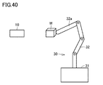
- FIG. 11 is a diagram showing still another mode in which the relative position between the work and the imaging device is changed.
- FIG. 1 is a schematic diagram showing an outline of a visual inspection system 1 according to the present embodiment.
- Appearance inspection system 1 includes, for example, a plurality of inspection target portions on an inspection target (hereinafter, also referred to as “work W”) mounted on stage 90 in an industrial product production line or the like. Is imaged, and the appearance of the work W is inspected using the obtained image. In the appearance inspection, the work W is inspected for scratches, dirt, presence or absence of foreign matter, dimensions, and the like.
- the next work W is transported onto the stage 90.
- the work W is placed at a predetermined position on the stage 90 in a predetermined posture.
- the appearance inspection system 1 includes an imaging device 10, an image processing device 20, a robot 30, a robot controller 40, a PLC (Programmable Logic Controller) 50, and a setting device 60.
- an imaging device 10 an image processing device 20
- a robot controller 40 a robot controller 40
- PLC Programmable Logic Controller
- the imaging device 10 is for imaging a subject existing in an imaging field of view and generating image data in accordance with a command from the image processing device 20, and captures a workpiece W to be subjected to a visual inspection as a subject.
- the image processing device 20 outputs an imaging command to the imaging device 10 in accordance with the command from the PLC 50.
- the image processing device 20 includes an inspection unit 21, a display control unit 22, a display device 23, and a storage device 120.
- the inspection unit 21 and the display control unit 22 are functional modules executed by the processor 110 (see FIG. 8) of the image processing device 20.
- the inspection unit 21 determines the appearance of the work W by performing a predetermined process on the image data generated by the imaging device 10.
- the display control unit 22 causes the display device 23 to display the determination result by the inspection unit 21.
- the output of the inspection result may be output to the display device 23 provided in the image processing device 20 or may be output to a display device (for example, a display 366 described later) provided in the setting device 60.
- the storage device 120 stores a three-dimensional model ML representing the shape of the work W.
- the three-dimensional model ML is, for example, three-dimensional design data indicating a surface of a new product or a new kind of work
- the robot 30 is, for example, a vertical articulated robot in which a plurality of arms 32 are connected on a base 31. Each connecting portion of the plurality of arms 32 includes a rotation shaft.
- the imaging device 10 is attached to the distal end of the distal arm 32a.
- the robot controller 40 controls the robot 30 according to a command from the PLC 50 to change the relative position between the work W and the imaging device 10 and the posture of the imaging device 10 with respect to the work W.
- the robot 30 can change the relative position between the work W and the imaging device 10 and the posture of the imaging device 10 with respect to the work W by changing the relative position and the posture of the imaging device 10 with respect to the stage 90. .
- the robot 30 moves the imaging device 10 using a coordinate system having a point on the stage 90 as the origin, whereby the relative position between the work W and the imaging device 10 and the posture of the imaging device 10 with respect to the work W Can be changed.
- the PLC 50 controls the robot controller 40 and the image processing device 20 so that the imaging device 10 sequentially captures a plurality of inspection target portions on the work W.
- the PLC 50 controls the robot controller 40 according to a path that satisfies the imaging conditions set by the setting device 60. Further, the PLC 50 controls the image processing device 20 so that the imaging device 10 outputs an imaging command at a timing that satisfies the designated imaging condition.
- the setting device 60 sets a path that satisfies imaging conditions including a relative position between the work W and the imaging device 10 for sequentially imaging a plurality of inspection target portions on the work W.
- the setting device 60 sets a path that satisfies the imaging conditions suitable for the work W when a new product or a new type of work W needs to be visually inspected.
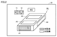
- FIG. 2 is a diagram illustrating an example of an inspection result displayed on the display device 23 of the image processing device 20.
- the inspection unit 21 of the image processing apparatus 20 performs a predetermined image process on each image obtained by photographing the workpiece W from a plurality of directions, thereby detecting a defect in each inspection target portion of the workpiece W. Check for presence.
- the inspection result is represented by, for example, one of “with defect” and “without defect”.
- the inspection process by the inspection unit 21 is executed each time the stage 90 transports the workpiece W to be inspected to a predetermined position.
- the display control unit 22 of the image processing device 20 displays the inspection result of each inspection target portion of the work W in a corresponding portion on the three-dimensional model ML.
- inspection target portions A1 to A4 are set in the three-dimensional model ML. Details of the method of setting the inspection target portions A1 to A4 will be described later.
- the display control unit 22 displays the inspection result of each of the inspection target portions A1 to A4 on each of the inspection target portions A1 to A4 on the three-dimensional model ML.
- the inspection target portion indicating a defect may be represented by a specific color (for example, red) or may be represented by blinking display.
- the inspection target portion indicating the defect is represented by a different color (for example, green) from the portion indicating the defect.
- the user can intuitively grasp which part in the inspection object the inspection result of each inspection target portion corresponds to.
- the display control unit 22 further displays, on the display device 23, a tool button 71 for rotating the three-dimensional model ML about the vertical direction and a tool button 72 for rotating the three-dimensional model ML about the horizontal direction. I do.
- the user can appropriately rotate the three-dimensional model ML by operating the tool buttons 71 and 72.
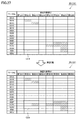
- FIG. 3 is a diagram showing a modification of the display mode of the inspection result.
- the inspection target portions of the work are arranged on the horizontal axis of the inspection result matrix 25 for each part name.
- Each part name may be registered in advance or may be set by the user.
- identification information of inspected works is arranged on the vertical axis of the inspection result matrix 25, identification information of inspected works is arranged.
- the work identification information is represented by, for example, a work serial number (hereinafter, also referred to as “work No.”) or a work name.
- the identification information of the work is represented by the work No.
- the display control unit 22 displays an inspection result of each inspection target portion of each work W on a corresponding cell.
- the inspection result of each inspection target portion of each work is represented two-dimensionally, so that the user can immediately grasp which portion of which work has a defect.
- the display of the inspection result in two dimensions becomes effective as the inspection result becomes enormous.
- the display control unit 22 highlights an inspection result indicating a defect among the inspection results included in the inspection result matrix 25 in a display mode different from other inspection results.
- the cell of the inspection result indicating a defect may be represented by a specific color (for example, red) or may be represented by a blinking display.
- cells indicating “with defect” are hatched, and cells indicating “no defect” are not hatched. Since the inspection result indicating the defect is highlighted in a display mode different from other inspection results, the user can easily determine the inspection result indicating the defect, and which part of which work has the defect. Can be grasped more easily.
- the inspection target portions of the work are arranged on the horizontal axis of the inspection result matrix 25 and the work numbers are arranged on the vertical axis of the inspection result matrix 25.
- 25 may be arranged on the horizontal axis, and the inspection target site of the work may be arranged on the vertical axis of the inspection result matrix 25.
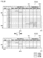
- Each row or each column of the inspection result matrix 25 is grouped in units of rows or columns according to a predetermined classification rule.
- the work parts “A1” to “A5” are grouped as a group GV1
- the work parts “B1” to “B3” are grouped. Grouped as GV2.
- the grouping of the inspection target portion of the work is performed according to the classification rule 134A shown in FIG.
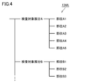
- FIG. 4 is a diagram showing an example of the data structure of the classification rule 134A.
- the inspection rule of the work W is hierarchically associated with the classification rule 134A.
- the correspondence between the parts may be registered in advance or may be arbitrarily set by the user.
- the inspection target part defined in the higher hierarchy has a relationship including the inspection target part defined in the lower hierarchy.
- the inspection target portion “A” is included in the portions “A1” to “A5”. That is, the parts “A1” to “A5” are areas in the inspection target part “A”.
- FIG. 5 is a diagram showing an example of the data structure of the classification rule 134B.
- each work to be inspected is hierarchically associated with the classification rule 134B.
- the hierarchical relationship of each work may be registered in advance or may be arbitrarily set by the user.
- each work is associated with a lot number of a production line.
- the lot number defined in the upper hierarchy has a relation including the work defined in the lower hierarchy.
- the lot number “001” is included in the work numbers “001A” to “001E”. In other words, it indicates that the work numbers “001A” to “001E” were produced in the lot number “001”.
- a development / aggregation button is assigned to each group of the inspection result matrix 25 in the vertical axis direction and the horizontal axis direction.
- the expand / aggregate button BH1 is assigned to the group GH1.
- the group GH2 is assigned an expand / consolidate button BH2.
- the group GV1 is assigned an expand / consolidate button BV1.
- the GV2 is assigned an expand / consolidate button BV2.
- FIG. 6 is a diagram showing screen transition of the inspection result matrix 25 when the deploy / aggregate button BV2 is pressed.
- the expansion / aggregation button BV2 alternately receives an aggregation instruction and an expansion instruction for cells in the group GV2 each time the button is pressed. That is, when the expansion / aggregation button BV2 is pressed while the cells of the group GV2 are expanded, the display control unit 22 of the image processing device 20 aggregates the cells of the group GV2 in a line.
- the display control unit 22 returns the display of the cells of the group GV2 to the state before the aggregation.
- the display control unit 22 changes the display of the inspection result “defect” to “no defect”. Is performed prior to the display of the inspection result of ".”
- the inspection result within the broken line AR1 includes one inspection result indicating “defective” and two inspection results indicating “no defect”.
- the three inspection results in the broken line AR1 are aggregated into one inspection result shown in the broken line AR2.
- the display control unit 22 expresses the inspection result after aggregation as “defective”.
- the display control unit 22 determines the inspection result after aggregation as “defect”. Yes ".
- the display control unit 22 determines that the inspection result after aggregation is “No defect”. ".
- FIG. 7 is a diagram showing screen transition of the inspection result matrix 25 when the deploy / aggregate button BH2 is pressed.
- the expansion / aggregation button BH2 alternately receives an aggregation instruction and an expansion instruction for cells in the group GH2 each time the button is pressed. That is, when the expansion / aggregation button BH2 is pressed while the cells of the group GH2 are expanded, the display control unit 22 aggregates the cells of the group GH2 into one row. On the other hand, when the expansion / aggregation button BH2 is pressed in a state where the cells of the group GH2 are aggregated, the display control unit 22 returns the display of the cells of the group GH2 to the state before the aggregation.
- the inspection results within the broken line AR3 include one inspection result indicating “defect” and nine inspection results indicating “no defect”.
- the ten inspection results in the broken line AR3 are aggregated into one inspection result shown in the broken line AR4.
- the display control unit 22 expresses the inspection result after aggregation as “defective”.
- the display control unit 22 of the image processing device 20 receives the aggregation instruction for the group of rows or the group of columns, the display control unit 22 displays the inspection result of the row group or the column group in one row. Or display them in a single row.
- the display control unit 22 receives an instruction to expand the inspection results that are collectively displayed, the display control unit 22 returns the display of the inspection results that are collectively displayed to the state before the aggregation.
- the display control unit 22 may display the cells after aggregation more densely as the number of inspection results indicating “defective” is included in the cells to be aggregated.
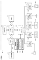
- FIG. 8 is a schematic diagram illustrating an example of a hardware configuration of the image processing apparatus 20.
- image processing device 20 typically has a structure according to a general-purpose computer architecture, and executes various programs such as a visual inspection process by executing a program installed in advance by a processor. Image processing is realized.
- the image processing apparatus 20 includes a processor 110 such as a CPU (Central Processing Unit) or an MPU (Micro-Processing Unit), a RAM (Random Access Memory) 112, a display controller 114, and a system controller 116. , An input / output (I / O) controller 118, a storage device 120 such as a hard disk, a camera interface 122, an input interface 124, a controller interface 126, a communication interface 128, and a memory card interface 130. These units are connected to each other so as to enable data communication with the system controller 116 as a center.
- the processor 110 exchanges programs (codes) with the system controller 116 and executes them in a predetermined order, thereby realizing a target arithmetic processing.
- the system controller 116 is connected to the processor 110, the RAM 112, the display controller 114, and the I / O controller 118 via buses, respectively, exchanges data with each unit, and performs processing of the entire image processing apparatus 20. Governing
- the RAM 112 is typically a volatile storage device such as a DRAM (Dynamic Random Access Memory), and includes a program read from the storage device 120, a camera image (image data) acquired by the imaging device 10, The processing result for the camera image, the work data, and the like are stored.
- DRAM Dynamic Random Access Memory
- the display controller 114 is connected to the display device 23, and outputs a signal for displaying various information to the display device 23 according to an internal command from the system controller 116.
- the I / O controller 118 controls data exchange between a recording medium connected to the image processing apparatus 20 and an external device. More specifically, I / O controller 118 is connected to storage device 120, camera interface 122, input interface 124, controller interface 126, communication interface 128, and memory card interface 130.
- the storage device 120 stores various data such as a project file 144 in addition to the image processing program 142 and the display program 143 executed by the processor 110. Details of the project file 144 will be described later.
- the storage device 120 may be a nonvolatile magnetic storage device such as a hard disk, a semiconductor storage device such as a flash memory, or a DVD-RAM (Digital Versatile Disk Random Access Memory). ) May be used.
- the image processing program 142 and the display program 143 may be provided by being incorporated in a part of another program. In that case, the image processing program 142 itself and the display program 143 itself execute a predetermined process in cooperation with another program. That is, the image processing program 142 and the display program 143 may be incorporated in such another program. Alternatively, some or all of the functions provided by executing the image processing program 142 or the display program 143 may be implemented as a dedicated hardware circuit.
- the camera interface 122 corresponds to an input unit that receives image data generated by photographing the work W, and mediates data transmission between the imaging device 10 and the processor 110. More specifically, the camera interface 122 can be connected to one or more imaging devices 10, and a shooting instruction is output from the processor 110 to the imaging device 10 via the camera interface 122. Thus, the imaging device 10 captures an image of a subject and outputs the generated image to the processor 110 via the camera interface 122.
- the input interface 124 mediates data transmission between the processor 110 and input devices such as a keyboard 134, a mouse, a touch panel, and a dedicated console.
- the controller interface 126 mediates data transmission between the PLC 50 and the processor 110. More specifically, the controller interface 126 transmits information on the state of the production line controlled by the PLC 50, information on the work W, and the like to the processor 110.
- the communication interface 128 mediates data transmission between the processor 110 and another personal computer or server device (not shown).
- the communication interface 128 is typically made of Ethernet (registered trademark), USB (Universal Serial Bus), or the like.
- the memory card interface 130 mediates data transmission between the processor 110 and the memory card 136 as a recording medium.
- the memory card 136 circulates with the image processing program 142 and the display program 143 executed by the image processing apparatus 20 stored therein, and the memory card interface 130 reads out these programs from the memory card 136.
- the memory card 136 may be a general-purpose semiconductor storage device such as SD (Secure Digital), a magnetic recording medium such as a flexible disk (Flexible Disk), or an optical recording medium such as a CD-ROM (Compact Disk Read Only Memory). Become.
- a program downloaded from a distribution server or the like may be installed in the image processing apparatus 20 via the communication interface 128.
- FIG. 9 is a schematic diagram illustrating an example of a hardware configuration of the PLC 50.
- the PLC 50 includes a chipset 212, a processor 214, a nonvolatile memory 216, a main memory 218, a system clock 220, a memory card interface 222, a communication interface 228, an internal bus controller 230, and a field bus controller 238. including.
- the chipset 212 and other components are respectively connected via various buses.
- the processor 214 and the chipset 212 typically have a configuration according to a general-purpose computer architecture. That is, the processor 214 interprets and executes the instruction codes sequentially supplied from the chipset 212 according to the internal clock.
- the chipset 212 exchanges internal data with various connected components and generates an instruction code necessary for the processor 214.
- the system clock 220 generates a system clock having a predetermined cycle and outputs the generated system clock to the processor 214.
- the chipset 212 has a function of caching data and the like obtained as a result of execution of arithmetic processing by the processor 214.
- the PLC 50 has a nonvolatile memory 216 and a main memory 218 as storage means.
- the non-volatile memory 216 stores an OS, a system program, a user program, log information, and the like in a non-volatile manner.
- the main memory 218 is a volatile storage area that holds various programs to be executed by the processor 214 and is also used as a work memory when executing various programs.
- the PLC 50 has a communication interface 228, an internal bus controller 230, and a field bus controller 238 as communication means. These communication circuits transmit and receive data.
- the communication interface 228 exchanges data with the image processing device 20 and the setting device 60.
- the PLC 50 outputs an imaging instruction to the image processing device 20 via the communication interface 228.
- the PLC 50 receives the result of the appearance inspection of the work W from the image processing device 20 via the communication interface 228.
- the internal bus controller 230 controls data exchange via the internal bus 226. More specifically, the internal bus controller 230 includes a DMA (Dynamic Memory Access) control circuit 232, an internal bus control circuit 234, and a buffer memory 236.
- DMA Dynamic Memory Access
- the memory card interface 222 connects the memory card 224 detachable to the PLC 50 and the processor 214.
- the fieldbus controller 238 is a communication interface for connecting to a field network.
- the PLC 50 is connected to the robot controller 40 via the field bus controller 238.
- the field network for example, EtherCAT (registered trademark), EtherNet / IP (registered trademark), CompoNet (registered trademark), or the like is employed.
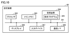
- FIG. 10 is a schematic diagram illustrating an example of a hardware configuration of the setting device 60.
- the setting device 60 includes a processor 362, a main memory 363, a storage device 364, a display 366, an input device 367, and a communication interface 368. These units are connected to each other via a bus 361 so as to be able to perform data communication.
- the processor 362 executes programs (codes) including the setting program 365 installed in the storage device 364 in the main memory 363 and executes them in a predetermined order, thereby performing various operations.
- the main memory 363 is typically a volatile storage device such as a DRAM (Dynamic Random Access Memory).
- the storage device 364 is an internal memory included in the setting device 60 and is a nonvolatile storage device, and stores various programs such as the setting program 365. Note that the storage device 364 may be a hard disk or a semiconductor storage device such as a flash memory.
- the setting program 365 is a program showing a procedure for setting a change path of the imaging condition by the setting device 60.
- Various programs such as the setting program 365 need not be stored in the storage device 364, but may be stored in a server that can communicate with the setting device 60 or an external memory that can be directly connected to the setting device 60.
- the program is distributed in a state where various programs executed by the setting device 60 and various parameters used in the various programs are stored in the external memory, and the setting device 60 reads the various programs and various parameters from the external memory.
- the external memory accumulates information of the program or the like by an electric, magnetic, optical, mechanical or chemical action so that the computer or other device or machine or the like can read the information of the recorded program or the like.
- programs and parameters downloaded from a server or the like communicably connected to the setting device 60 may be installed in the setting device 60.
- the display 366 is, for example, a liquid crystal display.
- the input device 367 includes, for example, a mouse, a keyboard, a touch pad, and the like.
- the communication interface 368 exchanges various data between the PLC 50 and the processor 362. Note that the communication interface 368 may exchange data between the server and the processor 362. Communication interface 368 includes hardware corresponding to a network for exchanging various data with PLC 50.
- FIG. 11 is a diagram showing an example of the data structure of the project file 144.
- the project file 144 includes an imaging condition file 146A, an image file group 146B, an inspection condition file 146C, an inspection result file 146D, a work information file 146E, a production information file 146F, and a classification rule file 146G. , And the expected value file 146H.
- the imaging condition file 146A is data that defines imaging conditions for each inspection target portion of the work W. That is, by referring to the imaging condition file 146A, the image processing apparatus 20 can uniquely specify the imaging condition using the inspection target portion as a key. Alternatively, the imaging condition may be uniquely specified using a combination of the work No. and the inspection target portion as a key.
- the imaging conditions include, for example, the relative position between the work W and the imaging device 10, the position of illumination when the work W is imaged, and the like.
- the image file group 146B is a data group obtained from the imaging device 10 by imaging the work W according to the defined imaging conditions.
- Each image file included in the image file group 146B is associated with a work number and an inspection target portion. That is, the image processing apparatus 20 can uniquely specify the image file used for the inspection using the combination of the work number and the inspection target portion as a key. Information on the combination of the work No. and the inspection target portion is specified, for example, in the file name of the image file or the header of the image file.
- the inspection condition file 146C is data defining the inspection conditions for each inspection target portion of the work. That is, the image processing apparatus 20 can uniquely specify the inspection condition as the inspection target partial key by referring to the inspection condition file 146C.
- the inspection conditions include, for example, an inspection target portion in an image, an image processing flowchart to be executed, a measurement parameter read at the time of execution of the image processing, a threshold for determining the presence or absence of a defect, and the like.
- the inspection result file 146D is data that defines measurement values, inspection results, and the like for each inspection target portion of each work. Details of the data structure of the inspection result file 146D will be described later.
- the work information file 146E includes a three-dimensional model representing the shape of the work to be inspected, type information of the work to be inspected, and the like.
- the production information file 146F is data for defining a lot number, a serial number, and the like of a work to be inspected.
- the classification rule file 146G is data including at least one of the above-described classification rule 134A (see FIG. 4), the above-described classification rule 134B (see FIG. 5), and the below-described classification rule 134C (see FIG. 30). .
- the expected value file 146H is data that specifies the expected value of the inspection result for each inspection target portion of each inspection target work. Details of the expected value file 146H will be described later.
- Inspection result file 146D > The inspection result file 146D included in the project file 144 (see FIG. 11) will be described with reference to FIG.
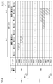
- FIG. 12 is a diagram showing an example of the data structure of the inspection result file 146D.
- the inspection result file 146D includes identification information of the work (for example, work No.), a part name indicating a part to be inspected of the work, a measurement value obtained as an output result of the inspection processing, and an inspection result indicating the presence or absence of a defect. Including.
- the image processing apparatus 20 can uniquely specify the measurement value and the inspection result by using the combination of the work number and the inspection target portion as a key by referring to the inspection result file 146D.
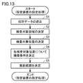
- FIG. 13 is a flowchart illustrating an example of a processing flow in the setting device 60.
- the setting device 60 performs processing according to, for example, a flowchart shown in FIG. A change path of the imaging condition suitable for is set.
- the three-dimensional design data indicating the design surface of the new or new type of workpiece W is stored in the storage device 364 of the setting device 60 in advance.
- step S1 the processor 362 of the setting device 60 reads the three-dimensional design data from the storage device 364.
- step S2 the processor 362 displays a schematic diagram showing the design appearance of the work W indicated by the three-dimensional design data on the display 366 of the setting device 60, and specifies the inspection target area on the work W according to the user input. decide.
- the processor 362 changes the coordinate system of the three-dimensional design data to a point on the stage 90. Convert to the XYZ coordinate system as the origin. Therefore, the inspection target area is indicated by an XYZ coordinate system having a point on the stage 90 as an origin.
- step S3 the processor 362 determines a plurality of inspection target positions from within the inspection target region so as to satisfy the inspection requirement corresponding to the inspection target region. That is, the processor 362 determines each of the plurality of inspection target positions determined in the inspection target region as an inspection target portion.
- step S4 the processor 362 determines an imaging condition including a relative position between the workpiece W and the imaging device 10 at the time of inspection for each of the plurality of inspection target positions.
- step S5 the processor 362 determines an imaging route so as to pass through the relative position between the workpiece W and the imaging device 10 determined in step S4.
- the inspection target area determined in step S2, the inspection target position determined in step S3, the imaging condition determined in step S4, and the imaging path determined in step S5 are transmitted to the image processing device 20 and the PLC 50. .
- a plurality of inspection target positions are determined from the inspection target portion in step S3.
- a plurality of inspection target portions may be determined in step S2, and in step S3, at least one inspection target position may be determined from each of the plurality of inspection target portions. Also in this case, a plurality of inspection target positions are determined in step S3.
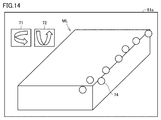
- FIG. 14 is a diagram illustrating an example of a screen on which a schematic diagram illustrating a design appearance of the work W is displayed.
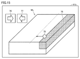
- FIG. 15 is a diagram illustrating an example of a screen on which an inspection target portion is displayed.
- the setting device 60 causes the display 366 to display a screen 61a including the three-dimensional model ML representing the shape of the work W.
- the screen 61a includes a tool button 71 for rotating the three-dimensional model ML about a vertical direction and a tool button 72 for rotating the three-dimensional model ML about a horizontal direction. The user can appropriately rotate the three-dimensional model ML by operating the tool buttons 71 and 72.
- the setting device 60 receives designation of a place to be inspected from the user. Specifically, the user uses the input device 367 to click a plurality of points on the three-dimensional model ML of the work W that the user wants to inspect. In the screen 61a shown in FIG. 14, a plurality of points clicked by the user are indicated by circles 74.
- the setting device 60 cuts out an area including a plurality of circles 74 specified on the three-dimensional model ML as an inspection target area. Specifically, the setting device 60 obtains a range within a predetermined distance from the point on the surface of the work W corresponding to each of the designated circles 74 along the surface, and sets the union of the ranges to the inspection target area. Cut out as.
- the setting device 60 further adjusts the inspection target area so that the contour is a geometric figure such as a straight line or a circle.
- the inspection target area 75 adjusted so that the contour is a straight line parallel to any one of the ridges of the workpiece W is shown.
- the setting device 60 receives a fine adjustment instruction of the inspection target area 75 from the user, and finely adjusts the inspection target area 75 according to the instruction.
- the screen 61b includes tool buttons 76 and 77 for enlarging or reducing the inspection target area 75.
- the user uses the input device 367 to select one side of the contour of the inspection target area 75 and operates the tool buttons 76 and 77 to input an instruction to enlarge or reduce the inspection target area 75.
- the user inputs an instruction to enlarge or reduce the inspection target area 75 by dragging a point 78 on one side constituting the contour of the inspection target area 75 using a mouse included in the input device 367. You may.
- the setting device 60 enlarges or reduces the inspection target area 75.
- the setting device 60 determines the inspection target area 75. In the example illustrated in FIG. 15, a region in which partial regions of four surfaces among the six surfaces of the rectangular parallelepiped work W are gathered is determined as the inspection target region 75.
- FIG. 16 is a diagram illustrating an example of a point on the inspection target area.
- FIG. 17 is a diagram illustrating an example of the inspection target position determined from the inspection target region and the corresponding effective visual field.
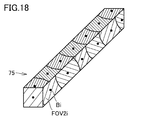
- FIG. 18 is a diagram illustrating all inspection target portions determined from the inspection target region and the effective visual field.
- the field of view of the imaging device 10 that can satisfy the inspection requirement that a defect of the minimum defect size can be recognized.
- the FOV is set as the inspection target part.
- the diameter of the imaging field of view FOV is generally represented by a ⁇ D ⁇ R using a proportionality constant a.
- the setting device 60 regards the inspection target area 75 as a set of points, and can investigate a three-dimensional shape near a point in the inspection target area 75 using the distribution of normal vectors. For example, based on the three-dimensional design data of the workpiece W, the setting device 60 obtains a distribution of normal vectors in a range within a distance L along a surface from a point in the inspection target area 75.
- the vicinity of the point P1 is flat. Therefore, all the normal vectors within the range of the distance L from the point P1 along the surface of the work W become the vector n2.
- Point P2 is located near the ridgeline where the two surfaces intersect. Therefore, the normal vector within the range of the distance L from the point P2 along the surface of the workpiece W includes the two vectors n2 and n4.
- Point P2 is located near the vertex where the three surfaces intersect. Therefore, the normal vectors within the range of the distance L from the point P3 along the surface of the workpiece W include three vectors n1, n2, and n4.
- the setting device 60 determines whether the vicinity of the point is flat or a ridgeline exists near the point by the distribution of the normal vectors within the distance L along the surface from the point in the inspection target area 75. Or whether there is a ridgeline near the point.
- the setting device 60 selects one point selected at random from the inspection target area 75 as the inspection target position Bi.
- the setting device 60 obtains the effective field of view FOV2i of the imaging device 10 for the inspection target position Bi as the inspection target portion.
- the effective visual field FOV2i is a visual field that includes the inspection target position Bi and can be imaged and inspected by the imaging device 10 using one imaging condition.
- the setting device 60 determines the effective field of view FOV2i according to the three-dimensional shape near the inspection target position Bi.
- the setting device 60 determines the effective visual field FOV2i so that the variation of the normal vector distribution in the effective visual field FOV2i falls within a predetermined range.
- the setting device 60 determines a range (that is, an imaging visual field FOV) within a distance a ⁇ D ⁇ R along the surface from the inspection target position Bi as the effective visual field FOV2i.
- a range that is, an imaging visual field FOV
- the setting device 60 moves the inspection target position Bi along the surface within a distance a ⁇ D ⁇ R within one distance.
- the range excluding the range of the portion is defined as the effective field of view FOV2i.
- the excluded range is the range of the surface having normal vectors other than the normal vector showing the maximum distribution amount in the normal vector distribution.
- the setting device 60 removes the set of points belonging to the determined effective field of view FOV2i from the set of points belonging to the inspection target area 75, and selects one point selected at random from the set of remaining points. Is selected as the inspection target position B (i + 1).
- the setting device 60 also determines the effective visual field FOV2 (i + 1) for the selected inspection target position B (i + 1).
- the setting device 60 repeats this processing until the set of points belonging to the inspection target area 75 becomes 0.
- the maximum possible diameter of the effective visual field FOV2i is set to the diameter of the imaging visual field FOV. Therefore, the inspection target position is determined so that the defect having the minimum defect size can be recognized in the entire inspection target region 75.
- the setting device 60 randomly extracts the inspection target position Bi from the inspection target region 75.
- the setting device 60 may extract the inspection target position Bi from the inspection target region 75 according to a predetermined geometric condition.
- the setting device 60 may extract the inspection target position Bi from the inspection target region 75 such that the plurality of extracted inspection target positions Bi are regularly aligned.
- the inspection target position may be determined so as to satisfy the inspection requirement that the inspection near the ridge or the vertex is preferentially performed.
- the inspection target position Bi may be preferentially extracted from a set of points in the inspection target area 75 where a ridgeline or a vertex exists within a predetermined distance.
- FIG. 19 is a diagram illustrating an example of a method of determining the photographing position Ci of the work W by the setting device 60.
- the setting device 60 determines the photographing position Ci on the normal line of the design appearance surface of the work W at the inspection target position Bi. More specifically, the photographing position Ci can capture an image of the effective field of view FOV2i corresponding to the inspection target position Bi, and is located at a position away from the inspection target position Bi by an optimal subject distance that is in focus with the inspection target position Bi. It is determined.
- the setting device 60 determines an imaging condition based on the determined imaging position Ci.
- the setting device 60 includes the inspection target position Bi in the field of view, and determines an optimal imaging condition for focusing on the inspection target position Bi.
- the imaging conditions include, for example, an X coordinate, a Y coordinate, and a Z coordinate of the imaging device 10 in an XYZ coordinate system whose origin is a point on the stage 90, and ⁇ x, ⁇ y, and ⁇ z that specify the direction of the optical axis of the imaging device 10.
- ⁇ x is the angle between the line that projects the optical axis of the imaging device 10 on the XY plane and the X axis
- ⁇ y is the angle that the line that projects the optical axis of the imaging device 10 on the YZ plane and the Y axis
- ⁇ z is the angle between the line that projects the optical axis of the imaging device 10 on the ZX plane and the Z axis.
- the XYZ coordinates are parameters for specifying a relative position between the work W and the imaging device 10
- ⁇ x, ⁇ y, and ⁇ z are parameters for specifying the posture of the imaging device 10 with respect to the work W.
- FIG. 20 is a diagram illustrating an example of the photographing route determined for the photographing position Ci.
- the setting device 60 determines a photographing route so as to pass through the decided photographing positions C1 to C7. At this time, the setting device 60 determines a photographing route so as to satisfy a predetermined requirement. For example, when the predetermined requirement is a requirement that minimizes the travel time, the setting device 60 sets a route candidate that has the shortest travel time among route candidates that sequentially pass through a plurality of imaging positions as an imaging route. Set. For example, the setting device 60 may calculate an evaluation value for evaluating an item (for example, travel time) indicated by a predetermined requirement for each route candidate, and set an imaging route based on the calculated evaluation value. .
- the setting device 60 selects one of the plurality of imaging position candidates as the imaging position based on the evaluation value. Good. In this way, a shooting path optimized to satisfy predetermined requirements is set.
- FIG. 20 shows the determined photographing route PS.
- the image sequentially passes through “shooting position C1” ⁇ “shooting position C4” ⁇ “shooting position C5” ⁇ “shooting position C6” ⁇ “shooting position C7” ⁇ “shooting position C3” ⁇ “shooting position C2”.
- the photographing path PS is determined so as to perform the operation.
- FIG. 21 is a flowchart illustrating an example of the flow of processing in the PLC 50.
- the processing illustrated in FIG. 21 is realized by the processor 214 of the PLC 50 executing a program. In other aspects, some or all of the processing may be performed by circuit elements or other hardware.
- the PLC 50 controls the robot controller 40 so that the imaging device 10 passes through the determined imaging path PS (see FIG. 20), and executes imaging at the imaging position Ci (see FIG. 20) where the imaging device 10 is determined.
- the image processing device 20 is controlled so as to perform the operation.
- step S10 the processor 214 determines whether or not the workpiece W placed on the stage 90 has been set at a predetermined position. If the processor 214 determines that the work W has been installed at a predetermined position (YES in step S10), it switches the control to step S12. Otherwise (NO in step S10), processor 214 executes the process of step S10 again.
- step S12 the processor 214 sequentially outputs a command value to the robot controller 40 according to a preset photographing path PS.
- the robot controller 40 drives each axis of the robot 30 according to a command value from the PLC 50.
- the imaging device 10 attached to the tip of the robot 30 sequentially moves along the imaging path PS.
- step S20 the processor 214 determines whether or not the imaging device 10 has reached a preset imaging position Ci (see FIG. 20). Whether or not the imaging device 10 has reached the preset imaging position Ci is determined, for example, based on a command value output to the robot controller 40 in step S12. When determining that the imaging device 10 has reached the preset imaging position Ci (YES in step S20), the processor 214 switches the control to step S22. Otherwise (NO in step S20), processor 214 switches the control to step S30.
- step S22 the processor 214 outputs a photographing instruction to the image processing device 20. Thereby, the image processing device 20 executes the photographing process.
- step S30 the processor 214 determines whether or not the imaging device 10 has reached the preset end point of the shooting path PS. Whether or not the imaging device 10 has reached the preset end point of the shooting path PS is determined, for example, based on a command value output to the robot controller 40 in step S12. If the processor 214 determines that the imaging device 10 has reached the preset end point of the shooting path PS (NO in step S30), the processor 214 returns the control to step S10. Otherwise (NO in step S30), processor 214 returns the control to step S12.
- FIG. 22 is a flowchart illustrating an example of the flow of an inspection process performed by the image processing apparatus 20.
- the processing illustrated in FIG. 22 is realized by the processor 110 of the image processing device 20 executing the image processing program 142 (see FIG. 8). Note that part or all of the processing may be executed by a circuit element or other hardware.
- step S50 the processor 110 determines whether or not a photographing instruction has been received from the PLC 50. As described above with reference to FIG. 21, the PLC 50 outputs a shooting instruction to the image processing device 20 when the imaging device 10 reaches a preset shooting position Ci. When determining that the photographing instruction has been received from the PLC 50 (YES in step S50), the processor 110 switches the control to step S52. Otherwise (NO in step S50), processor 110 switches the control to step S60.
- step S52 the processor 110 outputs a shooting instruction to the imaging device 10 as the above-described inspection unit 21 (see FIG. 1). Thereby, the imaging device 10 executes the photographing process based on receiving the photographing instruction from the image processing device 20. Thereby, the image processing device 20 can cause the imaging device 10 to execute the imaging process at the predetermined imaging position Ci.
- step S ⁇ b> 54 the processor 110 performs the inspection processing by executing predetermined image processing on the image obtained from the imaging device 10 as the inspection unit 21 described above.
- the image processing to be executed is specified, for example, in the above-described inspection condition file 146C (see FIG. 11).
- the inspection condition file 146C is data that defines inspection conditions for each inspection target portion of the work W. That is, by referring to the inspection condition file 146C, the image processing apparatus 20 can uniquely specify the inspection condition using the inspection target portion as a key.
- the processor 110 performs image processing on an image obtained according to the inspection condition acquired from the inspection condition file 146C, and obtains an inspection result.
- step S56 the processor 110 writes the test result obtained in step S54 in the test result file 146D (see FIG. 12) as the test unit 21 described above.
- the processor 110 determines the identification information of the work W (for example, work No.), the name of the part indicating the inspection target portion of the work W, the measurement value obtained as an output result of the inspection processing, and the inspection indicating the presence or absence of a defect. After being associated with the result, the result is written into the inspection result file 146D.
- step S60 the processor 110 determines whether or not an instruction to end the inspection processing has been received.
- processor 110 ends the inspection process shown in FIG. Otherwise (NO in step S60), processor 110 returns the control to step S50.
- the inspection process is executed each time the imaging process of the work W is executed.
- the imaging process of the work W and the inspection process on the image are performed separately. May be done. That is, the image processing apparatus 20 may first accumulate images, and then inspect the accumulated images collectively.
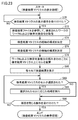
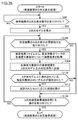
- FIG. 23 is a flowchart illustrating an example of the flow of the above-described inspection result matrix 25 display process.
- the processing illustrated in FIG. 23 is realized by the processor 110 of the image processing device 20 executing the display program 143 (see FIG. 8). Note that part or all of the processing may be executed by a circuit element or other hardware.
- step S70 the processor 110 determines whether a display operation of the inspection result matrix 25 has been received.
- the display operation is performed on an operation unit provided in the image processing device 20.
- the operation unit includes, for example, a keyboard 134 (see FIG. 8), a mouse, a touch panel, and the like.
- the processor 110 switches the control to step S72. Otherwise (NO in step S70), processor 110 executes the process of step S70 again.
- step S72 the processor 110 refers to the above-described inspection result file 146D (see FIG. 12) to determine the work No. defined in the inspection result file 146D and the inspection target part defined in the inspection result file 146D. To get.
- step S74 the processor 110 configures the vertical axis of the inspection result matrix 25 according to the work number acquired in step S72 as the display control unit 22 (see FIG. 1).
- the work numbers are arranged on the vertical axis of the inspection result matrix 25.
- step S76 the processor 110 configures the horizontal axis of the inspection result matrix 25 according to the inspection target portion of the workpiece acquired in step S74 as the display control unit 22 described above. As a result, the inspection target portions are arranged on the horizontal axis of the inspection result matrix 25.
- step S78 the processor 110, as the above-described display control unit 22, sets blank cells on the inspection result matrix 25 for each combination of the work No. acquired in step S72 and the inspection target portion of the work acquired in step S74. Deploy. Each cell is associated with a work number and an inspection target portion.
- the processor 110 refers to the inspection result file 146D and reflects the inspection result in each cell of the inspection result matrix 25. More specifically, the processor 110 acquires an inspection result for each combination of the work No. and the inspection target portion, and reflects the acquired inspection result in a cell corresponding to each combination. Typically, the processor 110 reflects the inspection result on each cell in such a manner that the inspection result of “defective” and the inspection result of “no defect” can be distinguished. As an example, if the inspection result indicates “defective”, the processor 110 displays the corresponding cell in a specific color (for example, red). On the other hand, if the inspection result indicates “no defect”, the processor 110 displays the corresponding cell in another color (for example, white or green).
- step S82 the processor 110 determines whether any cell in the inspection result matrix 25 has been selected.
- the selection operation is performed on an operation unit provided in the image processing device 20.
- the operation unit includes, for example, a keyboard 134 (see FIG. 8), a mouse, a touch panel, and the like.
- the processor 110 switches the control to step S84. Otherwise (NO in step S82), processor 110 switches the control to step S90.
- step S84 the processor 110 executes a process according to the selected cell as the inspection unit 21 (see FIG. 1) or the display control unit 22. That is, the processor 110 executes a process according to the combination of the specified work No. and the inspection target portion. Details of the processing executed in response to the cell selection operation will be described later.
- step S90 the processor 110 determines whether or not an operation for closing the inspection result matrix 25 has been received.
- processor 110 ends the process illustrated in FIG. Otherwise (NO in step S90), processor 110 returns the control to step S82.
- the image processing device 20 executes a process according to the selected cell based on the selection of the cell in the inspection result matrix 25. Examples of the processing that can be executed include the processing of specific examples 1 to 5 described below. Hereinafter, these processes will be described in order.
- the image processing device 20 executes at least one of the processes shown in the following specific examples 1 to 5 based on the reception of the cell selection operation.
- the image processing apparatus 20 may display the selection screen of the processing shown in the following specific examples 1 to 5 based on the reception of the cell selection operation and execute the processing selected on the selection screen. Good.
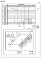
- FIG. 24 is a diagram illustrating a specific example 1 of a process performed in response to a cell selection operation.
- the cell CE1 in the inspection result matrix 25 is selected.
- the display control unit 22 of the image processing device 20 displays, on the display device 23, the image used for the inspection of the inspection target portion corresponding to the cell CE1 and the imaging conditions of the image. indicate. Thereby, the user can visually check the image indicating the defect, and can confirm the validity of the imaging conditions. Further, the user can easily confirm which part of the work the inspection target part shown in the inspection result matrix 25 indicates.
- the image processing apparatus 20 specifies a combination of the work No. and the inspection target portion associated with the selected cell CE1.
- the image processing apparatus 20 acquires a corresponding image file from the above-described image file group 146B (see FIG. 11) using the combination of the specified work number and the inspection target portion as a key.
- the image processing apparatus 20 acquires the corresponding imaging condition from the above-described imaging condition file 146A (see FIG. 11) using the specified inspection target portion as a key.
- the display control unit 22 displays the acquired image file and the imaging condition on the pop-up screen PU1 associated with the cell CE1.
- the displayed imaging condition is configured to be changeable to an arbitrary value.
- both the captured image and the imaging condition are displayed according to the cell selection operation.
- the display control unit 22 determines the captured image according to the cell selection operation.
- either one of the imaging condition and the imaging condition may be displayed.
- FIG. 25 is a diagram illustrating a specific example 2 of a process performed in response to a cell selection operation.
- the cell group CE2 in the inspection result matrix 25 is selected.
- the display control unit 22 of the image processing device 20 displays the three-dimensional model ML representing the shape of the work to be inspected on the display device 23 based on the selection of the cell group CE2, and corresponds to the cell group CE2.
- the inspection result of the inspection target portion is represented as a corresponding portion on the three-dimensional model ML.
- the display control unit 22 of the image processing apparatus 20 reads the three-dimensional model of the work to be inspected from the work information file 146E (see FIG. 11). ML is acquired, and the three-dimensional model ML is displayed on the pop-up screen PU2 associated with the cell group CE2.
- the image processing apparatus 20 acquires an inspection result corresponding to each combination of the specified work No. and the inspection target portion from the above-described inspection result file 146D (see FIG. 12).
- the image processing device 20 displays the inspection result of each inspection target portion in a corresponding location of the three-dimensional model ML.
- the display control unit 22 of the image processing device 20 can reflect the inspection result of each inspection target portion on the three-dimensional model ML based on the known information.
- the inspection target portions A3 to A5 corresponding to the selected cell group CE2 are reflected on the three-dimensional model ML.
- the display control unit 22 displays, on the three-dimensional model ML, the inspection target portion indicating “having a defect” in a display mode different from “no defect”.
- the inspection target portion indicating "having a defect” is represented by a specific color (for example, red) on the three-dimensional model ML, and the inspection target portion indicating "no defect” is represented by another color on the three-dimensional model ML. (Eg, green).
- the inspection target portion indicating “defect” may be represented by blinking display.
- the display control unit 22 further shows, on the three-dimensional model ML, an inspection target area 75A including the inspection target part A3 and an inspection target area 75B including the inspection target parts A4 and A5. Since the inspection target area is as described in FIG. 15, the description will not be repeated.
- the inspection target area 75B including the inspection target portion indicating “defective” is displayed in a different form from the inspection target region 75A not including the inspection target portion indicating “defective”.
- the inspection target area 75B may be represented by a specific color (for example, red) or may be represented by blinking display.
- the display control unit 22 displays a tool button 71 for rotating the three-dimensional model ML around the vertical direction and a tool button 72 for rotating the three-dimensional model ML around the horizontal direction on the pop-up screen PU2. To display further. The user can appropriately rotate the three-dimensional model ML by operating the tool buttons 71 and 72.
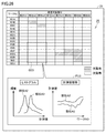
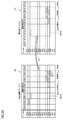
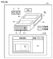
- FIG. 26 is a diagram illustrating a specific example 3 of the process performed in response to the cell selection operation.
- the cell group CE3 in the inspection result matrix 25 is selected.
- the display control unit 22 of the image processing device 20 displays the statistical result of the inspection result corresponding to the cell group CE3 on the display device 23 based on the selection of the cell group CE3. Thereby, the user can easily analyze the inspection result of an arbitrary inspection target portion.
- the image processing apparatus 20 specifies a combination of the work number and the inspection target portion associated with each cell of the selected cell group CE3. Next, the image processing apparatus 20 acquires the inspection result and the measurement value corresponding to each combination of the specified work No. and the inspection target portion from the above-described inspection result file 146D. Next, the image processing device 20 performs a predetermined statistical process on the acquired measurement value.
- the image processing device 20 generates a frequency distribution (that is, a histogram) by executing a predetermined statistical process.
- the horizontal axis of the histogram represents the division of the measurement value, and the horizontal axis of the histogram represents the frequency of the measurement value included in each division.
- the display control unit 22 of the image processing device 20 displays the generated histogram on the pop-up screen PU3 associated with the cell group CE3.
- the frequency distribution of the measurement values is generated for each selected inspection target portion.
- the frequency distribution is shown for each of the selected inspection target portions A2 and A3.
- the image processing device 20 generates a measured value transition graph by executing a predetermined statistical process.
- the horizontal axis of the measured value transition graph represents the work number, and the vertical axis of the measured value transition graph represents the measured value.
- the display control unit 22 of the image processing device 20 displays the generated measurement value transition graph on the pop-up screen PU3 associated with the cell group CE3.
- the measurement value transition graph is generated for each inspection target portion corresponding to the selected cell group CE3.
- a measured value transition graph is shown for each of the selected inspection target portions A2 and A3.
- FIG. 26 an example has been described in which two statistical results, a histogram and a measured value transition graph, are displayed in accordance with a cell group selection operation.
- the display control unit 22 selects the cell group. At least one statistical result may be displayed according to the operation.
- FIG. 27 is a diagram illustrating a specific example 4 of the process performed in response to the cell selection operation.
- the cell group CE4 in the inspection result matrix 25 is selected.
- the inspection unit 21 of the image processing device 20 re-examines the inspection target portion based on the selection of the cell group CE4 and based on the image used for the inspection of the inspection target portion corresponding to the cell group CE4. .
- the user can easily execute the re-inspection for an arbitrary inspection target portion.
- the user resets the inspection conditions, and then selects the cell group CE4 in the inspection result matrix 25.
- the inspection unit 21 specifies a combination of the work No. associated with each cell of the selected cell group CE4 and the inspection target portion.
- the inspection unit 21 acquires image data corresponding to each combination of the specified work No. and the inspection target portion from the image file group 146B.
- the inspection unit 21 acquires the inspection conditions corresponding to each of the specified inspection target portions from the above-described inspection condition file 146C.
- the inspection unit 21 performs image processing on each of the acquired image data according to the corresponding inspection conditions.
- the display control unit 22 reflects the result of the reinspection on the inspection result matrix 25.
- the number of selected cells may be one or more.
- FIG. 28 is a diagram illustrating a specific example 5 of the process performed in response to the cell selection operation.
- the cell group CE5 in the inspection result matrix 25 is selected.
- the display control unit 22 of the image processing device 20 displays the three-dimensional model ML of the work to be inspected on the display device 23 based on the selection of the cell group CE5, and also displays the inspection target portion corresponding to the cell group CE5. Are represented by corresponding parts on the three-dimensional model ML. Thereby, the user can easily confirm the imaging condition of the selected portion.
- the display control unit 22 of the image processing apparatus 20 stores the three-dimensional model ML of the work to be inspected in the work information file 146E described above (see FIG. 11). And displays the three-dimensional model ML on the pop-up screen PU5 associated with the cell group CE5.
- the image processing apparatus 20 acquires the imaging condition corresponding to each combination of the specified work No. and the inspection target portion from the above-described imaging condition file 146A (see FIG. 11).
- the display control unit 22 of the image processing apparatus 20 determines any one of the work numbers (for example, the minimum work number) from the work numbers corresponding to the cell group CE5, and corresponds to the determined work number.
- the respective imaging conditions to be performed are represented at corresponding locations of the three-dimensional model ML.
- the pop-up screen PU5 displays a return button 81 and a forward button 82. By pressing the return button 81 or the forward button 82, the user can switch the imaging conditions to be displayed in the order of work No. it can.
- the displayed imaging conditions include the imaging position of the imaging device 10 with respect to the three-dimensional model ML.
- the shooting position Ci of the imaging device 10 with respect to the three-dimensional model ML is determined by the setting process performed by the setting device 60. Is known. Therefore, the display control unit 22 of the image processing device 20 can display a schematic diagram representing the imaging device 10 on the imaging position Ci based on the known information. In the example of FIG. 28, a schematic diagram representing the imaging device 10 at the imaging positions C5 and C7 is displayed.
- the displayed imaging condition includes a portion to be inspected on the workpiece.
- the relationship between the three-dimensional model ML and the inspection target position Bi is known. Therefore, the display control unit 22 of the image processing device 20 can reflect the inspection result of each inspection target portion on the three-dimensional model ML based on the known information.
- the inspection target portions A5 and B1 are represented on the three-dimensional model ML.
- the imaging position and the inspection target portion are displayed as the imaging conditions
- the displayed imaging conditions are not limited to the imaging position and the inspection target portion.
- an optical condition such as an imaging field of view
- an illumination condition at the time of imaging may be displayed.
- FIG. 29 is a diagram showing a modification of the inspection result matrix 25 shown in FIG.
- Each row of the inspection result matrix 25 shown in FIG. 3 is grouped by the lot number of the work, whereas each row of the inspection result matrix 25 shown in FIG. 29 is grouped by the type of the work.
- the work type ⁇ has unique inspection target portions “A1” and “A3” which are not included in the work type ⁇ .
- the inspection results are reflected in the cells corresponding to the inspection target portions “A1” and “A3” of the work type ⁇ , but the inspection target portions “A1” and “A1” For the cell corresponding to “A3”, a blank is displayed as “not applicable”.
- FIG. 30 is a diagram illustrating an example of the data structure of the classification rule 134C.
- the inspection rule of the work W is hierarchically associated with the classification rule 134C.
- “A1” to “A4” are associated with the inspection target portion “A” of the work type ⁇ .
- “B1” and “B2” are associated with the inspection target portion “B” of the work type ⁇ .
- “A2”, “A4”, and “A5” are associated with the inspection target portion “A” of the work type ⁇ .
- “B1” to “B3” are associated with the inspection target portion “B” of the work type ⁇ .
- buttons are assigned to each group of the inspection result matrix 25 in the vertical axis direction and the horizontal axis direction.
- an expand / consolidate button BH1 is assigned to the group GH1.
- the group GH2 is assigned an expand / consolidate button BH2.
- the group GV1 is assigned an expand / consolidate button BV1.
- the group GV2 is assigned an expand / consolidate button BV2.
- FIG. 31 is a diagram showing a screen transition of the inspection result matrix 25 when the development / aggregation button BV2 is pressed.
- the expansion / aggregation button BV2 alternately receives an aggregation instruction and an expansion instruction for cells in the group GV2 each time the button is pressed. That is, when the expansion / aggregation button BV2 is pressed while the cells of the group GV2 are expanded, the display control unit 22 of the image processing device 20 aggregates the cells of the group GV2 in a line.
- the display control unit 22 returns the display of the cells of the group GV2 to the state before the aggregation.
- the display control unit 22 displays “defect existing” as “no defect”, “applicable”. Aggregation processing is performed with priority over the display of "None”. When the inspection results of “no defect” and “not applicable” are included in the cell to be consolidated, the display control unit 22 gives priority to the display of “no defect” over the display of “not applicable”. To perform aggregation processing.
- the broken line AR10 includes one “defective” cell and two “not applicable” cells.
- the three cells within the dashed line AR10 are aggregated into one cell indicated within the dashed line AR12.
- the display control unit 22 expresses the inspection result after aggregation as “defective”.
- the broken line AR11 includes two “no defect” cells and one “non-corresponding” cell.
- the three cells within the dashed line AR11 are aggregated into one cell indicated within the dashed line AR13.
- the display control unit 22 compares the inspection result after aggregation with “defect”. "None”.
- FIG. 32 is a diagram showing screen transition of the inspection result matrix 25 when the deploy / aggregate button BH2 is pressed.
- the expansion / aggregation button BH2 alternately receives an aggregation instruction and an expansion instruction for cells in the group GH2 each time the button is pressed. That is, when the expansion / aggregation button BH2 is pressed while the cells of the group GH2 are expanded, the display control unit 22 aggregates the cells of the group GH2 into one row. On the other hand, when the expansion / aggregation button BH2 is pressed in a state where the cells of the group GH2 are aggregated, the display control unit 22 returns the display of the cells of the group GH2 to the state before the aggregation.
- the broken line AR14 includes ten cells of “not applicable”. By the aggregation processing of the cells of the group GH2, the ten cells in the broken line AR14 are aggregated into one cell shown in the broken line AR15. At this time, since the cells before aggregation do not include the cells with “defect” and “without defect”, the display control unit 22 expresses the inspection result after aggregation as “not applicable”.
- the image processing apparatus 20 displays a comparison result between the expected value matrix indicating a true correct value (hereinafter, also referred to as an “expected value”) for each inspection result included in the inspection result matrix 25 and the inspection result matrix 25. It is displayed on the device 23. Thus, the user can easily determine whether each test result shown in the test result matrix 25 is as expected. Such comparison processing becomes more effective as the number of test results shown in the test result matrix 25 increases.
- FIG. 33 is a diagram schematically showing a comparison process between the inspection result matrix 25 and the expected value matrix 27.
- expected values are defined for at least a part of the inspection results included in the inspection result matrix 25.
- the expected value of each cell of the expected value matrix 27 is set, for example, by a user input.
- the expected value that can be input is, for example, one of “defective”, “no defect”, and “invalid”.
- the expected value matrix 27 set by the user is stored in the image processing apparatus 20 as the above-described expected value file 146H (see FIG. 11).
- the image processing apparatus 20 compares cells in the same row and the same column between each cell in the inspection result matrix 25 and each cell in the expected value matrix 27.
- the inspection result of the inspection result matrix 25 is “no defect” and the expected value of the expected value matrix 27 is “defective”, “missing” is output as the comparison result. “Missed” means that a defect to be detected has been missed. That is, "missing” indicates that the inspection result is not as expected.
- One reason that the comparison result is “missed” is that the threshold value for determining whether or not there is a defect is too loose.
- the inspection result of the inspection result matrix 25 is “defective” and the expected value of the expected value matrix 27 is “no defect”, “overdetected” is output as the comparison result.
- “Overdetection” means that a normal part has been detected as a defect. That is, “overdetected” indicates that the inspection result is not as expected.
- One reason that the comparison result is “overdetected” is that the threshold value for determining the presence / absence of a defect is too strict.
- a comparison result matrix 29 is output as a comparison result between the inspection result matrix 25 and the expected value matrix 27.
- the display control unit 22 displays the comparison result “correct answer OK”, “correct answer NG”, “missed”, “overdetected”, and “invalid” in a distinguishable manner. As an example, these comparison results may be distinguished by color or hatching type.
- the “correct answer OK” and “correct answer NG” that are the expected comparison results may be displayed in the same color (for example, white).
- the cell aggregation / expansion function may be implemented for the comparison result matrix 29.
- the display control unit 22 sets the cell after aggregation to “missing” or “overdetection”.
- the display control unit 22 sets the cell to be aggregated in a display mode indicating that both “missing” and “overdetection” are included.
- FIG. 34 is a diagram illustrating an example of a process of creating the expected value matrix 27.
- the image processing device 20 has a function of supporting creation of the expected value matrix 27.
- the user selects each cell of the inspection result matrix 25.
- the cell selection operation is performed on an operation unit provided in the image processing device 20.
- the operation unit includes, for example, a keyboard 134 (see FIG. 8), a mouse, a touch panel, and the like.
- the user copies the cell group CE10 of the inspection result matrix 25 to the expected value matrix 27 being edited. This eliminates the need for the user to input each cell of the expected value matrix 27 one by one, and reduces the time and effort of creating the expected value matrix 27.
- the expected value matrix 27 created by the user is stored in the image processing apparatus 20 as the above-described expected value file 146H (see FIG. 11).
- the image processing device 20 has a function of displaying the inspection result in three dimensions by reflecting the inspection result of the work on the three-dimensional model ML. The user can easily determine the location where the defect has occurred by checking the inspection result on the three-dimensional model ML.
- FIG. 35 is a flowchart illustrating an example of the flow of the three-dimensional display processing of the inspection result.
- the processing illustrated in FIG. 35 is realized by the processor 110 of the image processing device 20 executing the display program 143 (see FIG. 8). Note that part or all of the processing may be executed by a circuit element or other hardware.
- step S90 the processor 110 determines whether or not an execution operation of the three-dimensional display processing of the inspection result has been received.
- the display operation is performed on an operation unit provided in the image processing device 20.
- the operation unit includes, for example, a keyboard 134 (see FIG. 8), a mouse, a touch panel, and the like.
- step S92 the processor 110 acquires the three-dimensional model ML of the work from the work information file 146E (see FIG. 11) as the display control unit 22 (see FIG. 1), and outputs the acquired three-dimensional model ML. It is displayed on the display device 23.
- step S100 the processor 110 determines whether an instruction to update the three-dimensional display of the inspection result has been received.
- the update instruction is issued, for example, based on a new inspection result obtained from the inspection unit 21.
- the update instruction is issued based on the fact that the inspection unit 21 has detected the inspection result indicating the defect.
- the update instruction is issued based on a user operation.
- processor 110 switches the control to step S102. Otherwise (NO in step S100), processor 110 switches the control to step S120.
- step S102 the processor 110 refers to the above-described inspection result file 146D (see FIG. 12) to acquire inspection results for each inspection target portion of the work No. of the inspection target work.
- step S104 the processor 110, as the above-described display control unit 22, displays each inspection result acquired in step S102 in a corresponding location on the three-dimensional model ML displayed in step S92.
- the display control unit 22 of the image processing device 20 can reflect each inspection result acquired in step S102 on the three-dimensional model ML based on the known information.
- the processor 110 displays a portion indicating a defect in a display mode different from other portions.
- a portion indicating a defect may be represented by a specific color (for example, red) or may be represented by a blinking display. This makes it easier for the user to determine the portion indicating the defect.
- step S110 the processor 110 determines whether any of the inspection target portions shown on the three-dimensional model has been selected.
- the selection operation is performed on an operation unit provided in the image processing device 20.
- the operation unit includes, for example, a keyboard 134 (see FIG. 8), a mouse, a touch panel, and the like. If the processor 110 determines that any of the inspection target portions represented on the three-dimensional model has been selected (YES in step S110), it switches the control to step S112. Otherwise (NO in step S110), processor 110 switches the control to step S120.
- step S112 the processor 110 executes a process corresponding to the inspection target portion selected in step S110 as the inspection unit 21 or the display control unit 22 described above. Details of the processing executed in accordance with the selected inspection target portion will be described later.
- step S120 the processor 110 determines whether or not an operation to close the three-dimensional display screen of the inspection result has been received.
- processor 110 ends the process illustrated in FIG. Otherwise (NO in step S120), processor 110 returns the control to step S100.
- the three-dimensional display of the inspection result is updated when the instruction to update the three-dimensional display of the inspection result is issued in step S100.
- the update instruction is issued, for example, based on the inspection result indicating the defect being detected by the inspection unit 21. That is, when a defect is detected in the work to be sequentially inspected, the processor 110 updates the inspection result represented by the three-dimensional model ML with the inspection result of each inspection target portion of the work. As a result, while no inspection result indicating a defect is detected, the inspection result displayed on the three-dimensional model ML is not updated. Thus, the latest inspection result indicating the defect is always displayed on the three-dimensional model ML. Therefore, it is difficult for the user to overlook the inspection result indicating the defect.
- the image processing apparatus 20 responds to the selected inspection target portion based on selection of any of the inspection target portions shown in the three-dimensional model ML. Execute the process. Examples of the processing that can be executed include the processing of specific examples 1 and 2 described below. Hereinafter, these processes will be described in order.
- the image processing device 20 executes at least one of the processes shown in the following specific examples 1 and 2 based on receiving an operation of selecting an inspection target portion on the three-dimensional model ML. .
- the image processing device 20 displays the selection screen of the processing shown in the following specific examples 1 and 2 based on the selection operation of the inspection target portion on the three-dimensional model ML, and makes a selection on the selection screen. The performed processing may be executed.
- FIG. 36 is a diagram illustrating a specific example 1 of a process performed in response to a selection operation of an inspection target portion illustrated in the three-dimensional model ML.
- the display device 23 includes a three-dimensional model ML of the work to be inspected, a tool button 71 for rotating the three-dimensional model ML about the vertical direction, and a three-dimensional model ML about the horizontal direction.
- a tool button 72 for rotating the dimensional model ML is displayed. The user can appropriately rotate the three-dimensional model ML by operating the tool buttons 71 and 72.
- the inspection target position Bi is set with respect to the three-dimensional model ML, and thus the relationship between the three-dimensional model ML and the inspection target position Bi is known. Therefore, the display control unit 22 of the image processing device 20 can represent the inspection target portion on the three-dimensional model ML based on the known information. In the example of FIG. 36, the inspection target portions A1 to A4 are represented in the three-dimensional model ML.
- the display control unit 22 indicates the inspection result in the inspection target portions A1 to A4 on the three-dimensional model ML.
- the portion indicating “having a defect” may be represented by a specific color (for example, red) or may be represented by blinking display.
- the portion indicating “no defect” is represented by a different color (for example, green) from the portion indicating “defective”.
- the inspection target portion A1 indicates “defect”, and the inspection target portions A2 to A4 indicate “no defect”.
- the display control unit 22 highlights a defective portion A1_1 indicating a defect in the inspection target portion A1 more than other portions.
- the user can select any of the inspection target portions A1 to A4.
- the inspection target portion A1 is selected.
- the image processing device 20 displays, on the display device 23, the image used for the inspection of the inspection target portion A1 and the imaging conditions of the image based on the selection of the inspection target portion A1. Thereby, the user can visually check the image indicating the defect, and can confirm the validity of the imaging conditions.
- the image processing apparatus 20 uses the combination of the work No. of the inspection target work and the selected inspection target portion A1 as a key to generate a corresponding image file. From the image file group 146B (see FIG. 11). Next, the image processing apparatus 20 acquires the corresponding imaging condition from the above-described imaging condition file 146A (see FIG. 11) using the inspection target portion A1 as a key.
- the display control unit 22 displays the acquired image file and the imaging condition on the pop-up screen PU6 associated with the selected inspection target portion A1.
- the displayed imaging condition is configured to be changeable to an arbitrary value.
- both the captured image and the imaging condition are displayed according to the operation of selecting the inspection target portion.
- the display control unit 22 performs Accordingly, either one of the captured image and the imaging condition may be displayed.
- FIG. 37 is a diagram illustrating a specific example 2 of a process performed in response to an operation of selecting an inspection target portion illustrated in the three-dimensional model ML.
- the three-dimensional model ML includes inspection target portions A1 to A4.
- the user can select any of the inspection target portions A1 to A4.
- the inspection target portion A1 is selected.
- the image processing device 20 uses the combination of the work No. of the inspection target work and the selected inspection target portion A1 as a key to store corresponding imaging conditions in the above-described imaging condition file. 146A (see FIG. 11).
- the display control unit 22 of the image processing device 20 displays the acquired imaging conditions in corresponding locations of the three-dimensional model ML.
- the displayed imaging conditions include the imaging position of the imaging device 10 with respect to the three-dimensional model ML.
- the shooting position Ci of the imaging device 10 with respect to the three-dimensional model ML is determined by the setting process performed by the setting device 60. Is known. Therefore, the display control unit 22 of the image processing device 20 can display the schematic diagram 10A representing the imaging device 10 on the photographing position Ci based on the known information.
- a schematic diagram 10A of the imaging device 10 is displayed at the shooting position C1.
- the displayed imaging condition is not limited to the imaging position.
- an optical condition of the imaging device 10 at the time of imaging, an illumination condition at the time of imaging, and the like may be displayed.
- FIG. 38 is a diagram showing a process of developing / aggregating the inspection target portion shown in the three-dimensional model ML.
- the inspection target portion shown in the three-dimensional model ML is hierarchically associated with the above-described classification rule 134A (see FIG. 4).
- the inspection target part defined in the higher hierarchy has a relationship including the inspection target part defined in the lower hierarchy.
- the lower inspection target parts included in the inspection target part defined in the upper hierarchy are regarded as the same group.
- inspection target portions A to C are shown on the three-dimensional model ML. As an example, it is assumed that lower inspection target portions A1 to A3 are associated with upper inspection target portion A. The inspection target portions A1 to A3 included in the upper inspection target portion A are regarded as the same group.
- the lower inspection target portions A1_1 to A1_4 are associated with the upper inspection target portion A1.
- the inspection target portions A1_1 to A1_4 included in the upper inspection target portion A1 are regarded as the same group.
- Inspection results are shown in inspection target portions A to C on the three-dimensional model ML.
- the inspection results of the inspection target parts A to C are obtained from the inspection result file 146D (see FIG. 12).
- the inspection target portion A indicates “with defect”, and the inspection target portions B and C indicate “without defect”.
- the development / aggregation button BT1 is assigned to the inspection target portion A.
- the development / aggregation button BT2 is assigned to the inspection target portion B.
- the development / aggregation button BT3 is assigned to the inspection target portion C. “+” Indicates a development button, and “ ⁇ ” indicates an aggregation button.
- the display control unit 22 When the display control unit 22 receives the aggregation instruction for the grouped inspection target portions, the display control unit 22 aggregates the inspection results of the grouped inspection target portions, and displays the inspection results after the aggregation in the grouping. Each part on the three-dimensional model ML corresponding to the part to be inspected is represented. In addition, when the display control unit 22 receives a deployment instruction for the aggregated inspection results, the display control unit 22 returns the display of the aggregated inspection results to the state before the aggregation.
- the display control unit 22 when the deploy / aggregate button BT1 is pressed, the display control unit 22 deploys the inspection target part A to lower inspection target parts A1 to A3. Next, the display control unit 22 reflects the inspection results of the inspection target portions A1 to A3 on the inspection target portions A1 to A3.
- the inspection results of the inspection target parts A1 to A3 are obtained from the inspection result file 146D (see FIG. 12). As an example, the inspection target portion A1 indicates "having a defect", and the inspection target portions A2 and A3 indicate "no defect".
- the display control unit 22 assigns the deploy / aggregate button BT1_1 to the inspection target portion A1. Similarly, the display control unit 22 assigns a development / aggregation button BT1_2 to the inspection target portion A2. Similarly, the display control unit 22 assigns the deploy / aggregate button BT1_3 to the inspection target portion A3.
- the display control unit 22 expands the inspection target portion A1 into lower inspection target portions A1_1 to A1_4.
- the display control unit 22 reflects the inspection results of the inspection target portions A1_1 to A1_4 on the inspection target portions A1_1 to A1_4.
- the inspection results of the inspection target portions A1_1 to A1_4 are obtained from the inspection result file 146D (see FIG. 12).
- the inspection target portions A1_1 to A1_3 indicate "no defect", and the inspection target portion A1_4 indicates "defect".
- the display control unit 22 When the expand / combine button BT1_1A is pressed, the display control unit 22 combines the inspection target parts A1_1 to A1_4 into a higher-level inspection target part A1. At this time, when at least one inspection result indicating “having a defect” is included in the inspection result of the inspection target portion to be consolidated, the display control unit 22 displays the inspection result of the inspection target portion after the aggregation as “defective”. ". On the other hand, when no inspection result indicating “having a defect” is included in the inspection result of the inspection target portion to be consolidated, the display control unit 22 displays the inspection result of the inspection target portion after the aggregation as “no defect”. ". Since the inspection target portion A1_4 indicates “having a defect”, the display control unit 22 sets the inspection result of the inspection target portion A1 obtained by integrating the inspection target portions A1_1 to A1_4 to “having a defect”.
- the display control unit 22 When the “-” of the expand / combine button BT1 is pressed, the display control unit 22 combines the inspection target parts A1 to A3 into the inspection target part A. Since the inspection target portion A1 indicates "having a defect", the display control unit 22 sets the inspection result of the inspection target portion A obtained by integrating the inspection target portions A1 to A3 to "having a defect".
- FIG. 39 is a diagram illustrating a visual inspection system according to a modification.
- the appearance inspection system shown in FIG. 39 is different from the appearance inspection system 1 shown in FIG. 1 in that it does not include the PLC 50 and includes an image processing device 20a instead of the image processing device 20.
- the image processing device 20a has both the configuration of the image processing device 20 and the configuration of the PLC 50.
- FIG. 40 is a diagram showing another embodiment in which the relative position between the workpiece W and the imaging device 10 is changed.
- the robot 30 may move the work W instead of the imaging device 10.
- the imaging device 10 is fixed. By moving the work W in this manner, the relative position between the work W and the imaging device 10 may be changed.
- FIG. 41 is a diagram showing still another mode in which the relative position between the workpiece W and the imaging device 10 is changed.
- the workpiece W may be placed on the turntable 91.
- the rotary table 91 rotates according to an instruction from the robot controller 40. Thereby, the relative position between the workpiece W and the imaging device 10 can be easily changed.
- the robot 30 may be a robot other than the vertical articulated robot (for example, a horizontal articulated robot, an orthogonal robot, or the like).
- the imaging field of view FOV and the effective field of view FOV2 are described as being circular.
- the shapes of the imaging field of view FOV and the effective field of view FOV2 are not limited to circles, and may be, for example, rectangular (rectangular, square).
- this embodiment includes the following disclosure.
- a plurality of inspection portions of the inspection object (W) are imaged by the imaging device (10) while changing a relative position between the inspection object (W) and the imaging device (10), and the inspection object is captured.
- (W) a visual inspection system for performing visual inspection,
- ML three-dimensional model
- An inspection unit (21) A display for displaying the three-dimensional model (ML) on the display device (23) and displaying an inspection result of each inspection part of the inspection object (W) in a corresponding part on the three-dimensional model (ML).
- a visual inspection system comprising a control unit (22).
- the display control unit (22) is configured to, when expressing the inspection result of each inspection part of the inspection object (W) in a corresponding part on the three-dimensional model (ML), set a part indicating a defect as another part.
- the visual inspection system according to Configuration 1 or 2, wherein the visual inspection system displays the image in a different display mode.
- Each inspection part set for the three-dimensional model (ML) is grouped according to a predetermined classification rule,
- the display control unit (22) includes: When an aggregation instruction for a grouped inspection part is received, the inspection results of the grouped inspection part are aggregated, and the inspection result after aggregation is converted into the three-dimensional image corresponding to the grouped inspection part. Represented in each part on the model (ML), 4.
- the visual inspection system according to any one of Configurations 1 to 3, wherein, when a deployment instruction for the aggregated inspection result is received, the display of the aggregated inspection result is returned to a state before the aggregation.
- the visual inspection system further includes an operation unit (134) that can receive a selection operation of selecting one or more inspection parts from inspection parts represented on the three-dimensional model (ML),
- the display control unit (22) is configured to, based on the operation unit (134) receiving the selection operation, at least one of an image used for the inspection of the selected inspection part and an imaging condition of the image. Is displayed on the display device (23).
- the appearance inspection system according to any one of Configurations 1 to 5, wherein
- the inspection unit (21) sequentially performs an inspection process on a plurality of inspection objects (W), When a defect is detected in the inspection object (W) sequentially inspected, the display control unit (22) uses the inspection result of each inspection part of the inspection object (W) to execute the three-dimensional model (ML). 7.
- the visual inspection system according to any one of Configurations 1 to 6, wherein the inspection result is updated.
- [Configuration 8] Visual inspection performed by imaging a plurality of inspection portions of the inspection object (W) with the imaging device (10) while changing the relative position between the inspection object (W) and the imaging device (10). How to display the results, Acquiring a three-dimensional model (ML) representing the shape of the inspection object (W), wherein a plurality of inspection portions of the inspection object (W) are preset with respect to the three-dimensional model (ML).
- ML three-dimensional model
- [Configuration 9] Visual inspection performed by imaging a plurality of inspection portions of the inspection object (W) with the imaging device (10) while changing the relative position between the inspection object (W) and the imaging device (10).
- a result display program The display program, the computer, Acquiring a three-dimensional model (ML) representing the shape of the inspection object (W), wherein a plurality of inspection portions of the inspection object (W) are preset with respect to the three-dimensional model (ML).
- 1 appearance inspection system 10 imaging device, 10A schematic diagram, 20, 20a image processing device, 21 inspection unit, 22 display control unit, 23 display device, 25 inspection result matrix, 27 expected value matrix, 29 comparison result matrix, 30 robot , 31 base, 32 arm, 32a tip arm, 40 robot controller, 50 PLC, 60 setting device, 61a, 61b screen, 71, 72, 76, 77 tool button, 74 circle, 75, 75A, 75B inspection target area , 81 back button, 82 forward button, 90 stage, 91 rotary table, 110, 214, 362 processor, 112 RAM, 114 display controller, 116 system controller, 118 I / O controller, 120, 364 storage device 122, camera interface, 124, input interface, 126, controller interface, 128, 228, 368, communication interface, 130, 222 memory card interface, 134 keyboard, 134A, 134B, 134C classification rule, 136, 224 memory card, 142 image processing program, 143 display program, 144 project file, 146A imaging condition file,
Landscapes
- Physics & Mathematics (AREA)
- Health & Medical Sciences (AREA)
- Life Sciences & Earth Sciences (AREA)
- Chemical & Material Sciences (AREA)
- Analytical Chemistry (AREA)
- Biochemistry (AREA)
- General Health & Medical Sciences (AREA)
- General Physics & Mathematics (AREA)
- Immunology (AREA)
- Pathology (AREA)
- Investigating Materials By The Use Of Optical Means Adapted For Particular Applications (AREA)
Abstract
La présente invention permet à un utilisateur de déterminer intuitivement la correspondance entre des résultats d'inspection de sites et d'emplacements cibles d'inspection individuels dans une cible d'inspection (W). L'invention concerne un système d'inspection d'apparence externe qui comporte : un dispositif d'affichage (23) ; et un dispositif de stockage, qui stocke un modèle tridimensionnel (ML) représentant la forme de la cible d'inspection (W). Une pluralité de sites d'inspection de la cible d'inspection (W) sont définis à l'avance dans le modèle tridimensionnel (ML). Le système d'inspection d'apparence externe comprend : une unité d'inspection (21) qui inspecte, sur la base d'images individuelles obtenues à partir d'un dispositif d'acquisition d'image (10) à la suite d'une acquisition d'images des sites respectifs d'inspection de la cible d'inspection (W), les sites d'inspection respectifs de la cible d'inspection (W) pour y détecter la présence/l'absence d'un défaut ; et une unité de commande d'affichage (22), qui amène le modèle tridimensionnel (ML) à s'afficher sur le dispositif d'affichage (23) et qui provoque l'affichage des résultats d'inspection pour les sites d'inspection respectifs de la cible d'inspection (W) sur des sites correspondants du modèle tridimensionnel (ML).
Applications Claiming Priority (2)
| Application Number | Priority Date | Filing Date | Title |
|---|---|---|---|
| JP2018122069A JP7070153B2 (ja) | 2018-06-27 | 2018-06-27 | 外観検査システム、外観検査結果の表示方法、および、外観検査結果の表示プログラム |
| JP2018-122069 | 2018-06-27 |
Publications (1)
| Publication Number | Publication Date |
|---|---|
| WO2020003888A1 true WO2020003888A1 (fr) | 2020-01-02 |
Family
ID=68984999
Family Applications (1)
| Application Number | Title | Priority Date | Filing Date |
|---|---|---|---|
| PCT/JP2019/021683 Ceased WO2020003888A1 (fr) | 2018-06-27 | 2019-05-31 | Système d'inspection d'apparence externe, procédé d'affichage de résultat d'inspection d'apparence externe et programme d'affichage de résultat d'inspection d'apparence externe |
Country Status (2)
| Country | Link |
|---|---|
| JP (1) | JP7070153B2 (fr) |
| WO (1) | WO2020003888A1 (fr) |
Cited By (5)
| Publication number | Priority date | Publication date | Assignee | Title |
|---|---|---|---|---|
| US20210302323A1 (en) * | 2020-03-30 | 2021-09-30 | Sintokogio, Ltd. | Display control device and storage medium |
| CN115292964A (zh) * | 2022-09-28 | 2022-11-04 | 中科航迈数控软件(深圳)有限公司 | 加工部件的可视化寿命管理方法、系统、终端及存储介质 |
| US11802842B2 (en) | 2020-03-30 | 2023-10-31 | Sintokogio, Ltd. | Display control device and storage medium |
| US11810286B2 (en) | 2020-03-30 | 2023-11-07 | Sintokogio, Ltd. | Display control device and storage medium |
| US11893723B2 (en) | 2020-03-30 | 2024-02-06 | Sintokogio, Ltd. | Inspection result display device and storage medium |
Families Citing this family (6)
| Publication number | Priority date | Publication date | Assignee | Title |
|---|---|---|---|---|
| JP2021148593A (ja) * | 2020-03-19 | 2021-09-27 | 株式会社Screenホールディングス | 検査システム、検査結果の表示方法および表示プログラム |
| JP7506565B2 (ja) * | 2020-09-14 | 2024-06-26 | 株式会社Screenホールディングス | 画像処理装置、検査装置およびプログラム |
| WO2023248573A1 (fr) * | 2022-06-24 | 2023-12-28 | 富士フイルム株式会社 | Dispositif, procédé et programme de commande d'affichage |
| JP7707249B2 (ja) * | 2023-09-06 | 2025-07-14 | 川崎重工業株式会社 | 検査システムおよび検査方法 |
| JP7654733B2 (ja) * | 2023-09-06 | 2025-04-01 | 川崎重工業株式会社 | 検査システムおよび検査方法 |
| TWI911904B (zh) * | 2023-09-06 | 2026-01-11 | 日商川崎重工業股份有限公司 | 檢查系統、檢查方法及機器人系統 |
Citations (9)
| Publication number | Priority date | Publication date | Assignee | Title |
|---|---|---|---|---|
| JPS59153151A (ja) * | 1983-02-21 | 1984-09-01 | Dainippon Printing Co Ltd | 規則性パタ−ンの欠陥検査装置 |
| JPS62110138A (ja) * | 1985-11-08 | 1987-05-21 | Nissan Motor Co Ltd | 表面欠陥検査装置のデ−タ出力方法 |
| JPS63141332A (ja) * | 1986-12-03 | 1988-06-13 | Hitachi Electronics Eng Co Ltd | 面板欠陥デ−タのズ−ミングマツプ表示方式 |
| JPH01187438A (ja) * | 1988-01-22 | 1989-07-26 | Hitachi Electron Eng Co Ltd | ディスク欠陥の密集箇所のズーミング表示方式 |
| JP2000004079A (ja) * | 1998-06-12 | 2000-01-07 | Omron Corp | はんだ検査装置 |
| JP2007281500A (ja) * | 1998-11-30 | 2007-10-25 | Hitachi Ltd | 回路パターンの検査装置、検査システム、および検査方法 |
| JP2010177293A (ja) * | 2009-01-27 | 2010-08-12 | Omron Corp | 部品実装基板の品質管理用の情報表示システムおよび情報表示方法 |
| JP2014132437A (ja) * | 2013-01-02 | 2014-07-17 | Boeing Co | 航空機構造体の遠隔検査のためのシステム及び方法 |
| US20160328835A1 (en) * | 2011-09-28 | 2016-11-10 | Kurion, Inc. | Automatic detection of defects in composite structures using ndt methods |
Family Cites Families (6)
| Publication number | Priority date | Publication date | Assignee | Title |
|---|---|---|---|---|
| JP2748977B2 (ja) * | 1988-09-12 | 1998-05-13 | オムロン株式会社 | 基板検査結果表示装置 |
| JP4974796B2 (ja) | 2007-07-13 | 2012-07-11 | シャープ株式会社 | 表示装置および表示方法 |
| JP5077011B2 (ja) | 2008-03-26 | 2012-11-21 | 富士通株式会社 | 表示制御装置、表示制御方法、及び、表示制御プログラム |
| US20100228752A1 (en) | 2009-02-25 | 2010-09-09 | Microsoft Corporation | Multi-condition filtering of an interactive summary table |
| JP2017062160A (ja) | 2015-09-24 | 2017-03-30 | アイシン精機株式会社 | 欠陥検査装置および欠陥検査方法 |
| JP6827793B2 (ja) | 2016-12-16 | 2021-02-10 | 三菱パワー株式会社 | 管理装置、それを備えたボイラシステム、並びに識別情報の管理方法 |
-
2018
- 2018-06-27 JP JP2018122069A patent/JP7070153B2/ja active Active
-
2019
- 2019-05-31 WO PCT/JP2019/021683 patent/WO2020003888A1/fr not_active Ceased
Patent Citations (9)
| Publication number | Priority date | Publication date | Assignee | Title |
|---|---|---|---|---|
| JPS59153151A (ja) * | 1983-02-21 | 1984-09-01 | Dainippon Printing Co Ltd | 規則性パタ−ンの欠陥検査装置 |
| JPS62110138A (ja) * | 1985-11-08 | 1987-05-21 | Nissan Motor Co Ltd | 表面欠陥検査装置のデ−タ出力方法 |
| JPS63141332A (ja) * | 1986-12-03 | 1988-06-13 | Hitachi Electronics Eng Co Ltd | 面板欠陥デ−タのズ−ミングマツプ表示方式 |
| JPH01187438A (ja) * | 1988-01-22 | 1989-07-26 | Hitachi Electron Eng Co Ltd | ディスク欠陥の密集箇所のズーミング表示方式 |
| JP2000004079A (ja) * | 1998-06-12 | 2000-01-07 | Omron Corp | はんだ検査装置 |
| JP2007281500A (ja) * | 1998-11-30 | 2007-10-25 | Hitachi Ltd | 回路パターンの検査装置、検査システム、および検査方法 |
| JP2010177293A (ja) * | 2009-01-27 | 2010-08-12 | Omron Corp | 部品実装基板の品質管理用の情報表示システムおよび情報表示方法 |
| US20160328835A1 (en) * | 2011-09-28 | 2016-11-10 | Kurion, Inc. | Automatic detection of defects in composite structures using ndt methods |
| JP2014132437A (ja) * | 2013-01-02 | 2014-07-17 | Boeing Co | 航空機構造体の遠隔検査のためのシステム及び方法 |
Cited By (6)
| Publication number | Priority date | Publication date | Assignee | Title |
|---|---|---|---|---|
| US20210302323A1 (en) * | 2020-03-30 | 2021-09-30 | Sintokogio, Ltd. | Display control device and storage medium |
| US11796482B2 (en) * | 2020-03-30 | 2023-10-24 | Sintokogio, Ltd. | Display control device and storage medium |
| US11802842B2 (en) | 2020-03-30 | 2023-10-31 | Sintokogio, Ltd. | Display control device and storage medium |
| US11810286B2 (en) | 2020-03-30 | 2023-11-07 | Sintokogio, Ltd. | Display control device and storage medium |
| US11893723B2 (en) | 2020-03-30 | 2024-02-06 | Sintokogio, Ltd. | Inspection result display device and storage medium |
| CN115292964A (zh) * | 2022-09-28 | 2022-11-04 | 中科航迈数控软件(深圳)有限公司 | 加工部件的可视化寿命管理方法、系统、终端及存储介质 |
Also Published As
| Publication number | Publication date |
|---|---|
| JP2020003301A (ja) | 2020-01-09 |
| JP7070153B2 (ja) | 2022-05-18 |
Similar Documents
| Publication | Publication Date | Title |
|---|---|---|
| JP7070153B2 (ja) | 外観検査システム、外観検査結果の表示方法、および、外観検査結果の表示プログラム | |
| JP6405320B2 (ja) | 物的資産の改良された自動外観検査のための方法およびシステム | |
| US10133256B2 (en) | Information processing apparatus and method for calculating inspection ranges | |
| WO2020003887A1 (fr) | Système d'inspection d'apparence externe, procédé d'affichage de résultat d'inspection d'apparence externe et programme d'affichage de résultat d'inspection d'apparence externe | |
| JP2011222636A (ja) | 検査装置,検査方法、及び欠陥座標補正方法 | |
| WO2022187866A1 (fr) | Contrôle et gestion de compatibilité de performance virtuelle de construction modulaire et procédés associés | |
| JP4958114B2 (ja) | 情報処理装置、情報処理方法、コンピュータプログラム | |
| JP2014126494A (ja) | 検査支援装置、検査支援方法、ロボットシステム、制御装置、ロボット、及び、プログラム | |
| JP2009146075A (ja) | 画像処理コントローラ及び検査支援システム | |
| JP6915288B2 (ja) | 画像処理システム、画像処理装置、FPGA(Field Programmable Gate Array)における回路の再構成方法、および、FPGAにおける回路の再構成プログラム | |
| JP2018005500A (ja) | 画像処理システム、画像処理方法、および画像処理プログラム | |
| JP4929133B2 (ja) | 検査支援システム | |
| JP2020204805A (ja) | 表示方法、画像生成装置、及び、プログラム | |
| JP7146367B2 (ja) | 画像処理システム、情報処理装置、情報処理方法、および情報処理プログラム | |
| JP7409199B2 (ja) | 外観検査経路探索方法、外観検査ロボットの検査経路探索装置、検査経路探索プログラム、および、外観検査ロボット | |
| JP5445064B2 (ja) | 画像処理装置および画像処理プログラム | |
| JP2007192743A (ja) | 画像取り込み方法並びに検査方法及びその装置 | |
| JP2022093132A (ja) | 学習装置、その制御方法、および制御プログラム、並びに推定装置、その制御方法、および制御プログラム | |
| JP2018124605A (ja) | 画像処理システム、情報処理装置、情報処理方法、および、情報処理プログラム | |
| JP2020077397A (ja) | 画像処理方法、画像処理装置、生産システム、物品の製造方法、プログラム、および記録媒体 | |
| CN117790349A (zh) | Pcs电测不良缺陷显示方法、装置、设备及存储介质 | |
| JP7067869B2 (ja) | 画像処理システム、情報処理装置、情報処理方法、および情報処理プログラム | |
| JP6293293B2 (ja) | マルチセンサ計測装置のルーティンを確立する方法 | |
| CN115113863B (zh) | 一种机器视觉系统可执行程序的生成方法及平台 | |
| JP2016125846A (ja) | データ処理装置、データ処理方法、及び、プログラム |
Legal Events
| Date | Code | Title | Description |
|---|---|---|---|
| 121 | Ep: the epo has been informed by wipo that ep was designated in this application |
Ref document number: 19824693 Country of ref document: EP Kind code of ref document: A1 |
|
| NENP | Non-entry into the national phase |
Ref country code: DE |
|
| 122 | Ep: pct application non-entry in european phase |
Ref document number: 19824693 Country of ref document: EP Kind code of ref document: A1 |