WO2020003900A1 - Structure de jonction et son procédé de fabrication - Google Patents
Structure de jonction et son procédé de fabrication Download PDFInfo
- Publication number
- WO2020003900A1 WO2020003900A1 PCT/JP2019/021881 JP2019021881W WO2020003900A1 WO 2020003900 A1 WO2020003900 A1 WO 2020003900A1 JP 2019021881 W JP2019021881 W JP 2019021881W WO 2020003900 A1 WO2020003900 A1 WO 2020003900A1
- Authority
- WO
- WIPO (PCT)
- Prior art keywords
- plate
- joined
- welding
- shaped member
- joint structure
- Prior art date
- Legal status (The legal status is an assumption and is not a legal conclusion. Google has not performed a legal analysis and makes no representation as to the accuracy of the status listed.)
- Ceased
Links
Images



Classifications
-
- B—PERFORMING OPERATIONS; TRANSPORTING
- B23—MACHINE TOOLS; METAL-WORKING NOT OTHERWISE PROVIDED FOR
- B23K—SOLDERING OR UNSOLDERING; WELDING; CLADDING OR PLATING BY SOLDERING OR WELDING; CUTTING BY APPLYING HEAT LOCALLY, e.g. FLAME CUTTING; WORKING BY LASER BEAM
- B23K9/00—Arc welding or cutting
- B23K9/02—Seam welding; Backing means; Inserts
-
- B—PERFORMING OPERATIONS; TRANSPORTING
- B21—MECHANICAL METAL-WORKING WITHOUT ESSENTIALLY REMOVING MATERIAL; PUNCHING METAL
- B21D—WORKING OR PROCESSING OF SHEET METAL OR METAL TUBES, RODS OR PROFILES WITHOUT ESSENTIALLY REMOVING MATERIAL; PUNCHING METAL
- B21D22/00—Shaping without cutting, by stamping, spinning, or deep-drawing
-
- B—PERFORMING OPERATIONS; TRANSPORTING
- B23—MACHINE TOOLS; METAL-WORKING NOT OTHERWISE PROVIDED FOR
- B23B—TURNING; BORING
- B23B3/00—General-purpose turning-machines or devices, e.g. centre lathes with feed rod and lead screw; Sets of turning-machines
- B23B3/04—Turning-machines in which the workpiece is rotated by means at a distance from the headstock
-
- B—PERFORMING OPERATIONS; TRANSPORTING
- B23—MACHINE TOOLS; METAL-WORKING NOT OTHERWISE PROVIDED FOR
- B23K—SOLDERING OR UNSOLDERING; WELDING; CLADDING OR PLATING BY SOLDERING OR WELDING; CUTTING BY APPLYING HEAT LOCALLY, e.g. FLAME CUTTING; WORKING BY LASER BEAM
- B23K26/00—Working by laser beam, e.g. welding, cutting or boring
- B23K26/20—Bonding
- B23K26/21—Bonding by welding
- B23K26/24—Seam welding
- B23K26/242—Fillet welding, i.e. involving a weld of substantially triangular cross section joining two parts
-
- B—PERFORMING OPERATIONS; TRANSPORTING
- B23—MACHINE TOOLS; METAL-WORKING NOT OTHERWISE PROVIDED FOR
- B23K—SOLDERING OR UNSOLDERING; WELDING; CLADDING OR PLATING BY SOLDERING OR WELDING; CUTTING BY APPLYING HEAT LOCALLY, e.g. FLAME CUTTING; WORKING BY LASER BEAM
- B23K26/00—Working by laser beam, e.g. welding, cutting or boring
- B23K26/20—Bonding
- B23K26/21—Bonding by welding
- B23K26/24—Seam welding
- B23K26/244—Overlap seam welding
-
- B—PERFORMING OPERATIONS; TRANSPORTING
- B23—MACHINE TOOLS; METAL-WORKING NOT OTHERWISE PROVIDED FOR
- B23K—SOLDERING OR UNSOLDERING; WELDING; CLADDING OR PLATING BY SOLDERING OR WELDING; CUTTING BY APPLYING HEAT LOCALLY, e.g. FLAME CUTTING; WORKING BY LASER BEAM
- B23K26/00—Working by laser beam, e.g. welding, cutting or boring
- B23K26/346—Working by laser beam, e.g. welding, cutting or boring in combination with welding or cutting covered by groups B23K5/00 - B23K25/00, e.g. in combination with resistance welding
- B23K26/348—Working by laser beam, e.g. welding, cutting or boring in combination with welding or cutting covered by groups B23K5/00 - B23K25/00, e.g. in combination with resistance welding in combination with arc heating, e.g. tungsten inert gas [TIG], metal inert gas [MIG] or plasma welding
-
- B—PERFORMING OPERATIONS; TRANSPORTING
- B23—MACHINE TOOLS; METAL-WORKING NOT OTHERWISE PROVIDED FOR
- B23K—SOLDERING OR UNSOLDERING; WELDING; CLADDING OR PLATING BY SOLDERING OR WELDING; CUTTING BY APPLYING HEAT LOCALLY, e.g. FLAME CUTTING; WORKING BY LASER BEAM
- B23K31/00—Processes relevant to this subclass, specially adapted for particular articles or purposes, but not covered by any single one of main groups B23K1/00 - B23K28/00
- B23K31/02—Processes relevant to this subclass, specially adapted for particular articles or purposes, but not covered by any single one of main groups B23K1/00 - B23K28/00 relating to soldering or welding
- B23K31/022—Making profiled bars with soldered or welded seams
-
- B—PERFORMING OPERATIONS; TRANSPORTING
- B62—LAND VEHICLES FOR TRAVELLING OTHERWISE THAN ON RAILS
- B62D—MOTOR VEHICLES; TRAILERS
- B62D27/00—Connections between superstructure or understructure sub-units
- B62D27/02—Connections between superstructure or understructure sub-units rigid
-
- B—PERFORMING OPERATIONS; TRANSPORTING
- B23—MACHINE TOOLS; METAL-WORKING NOT OTHERWISE PROVIDED FOR
- B23K—SOLDERING OR UNSOLDERING; WELDING; CLADDING OR PLATING BY SOLDERING OR WELDING; CUTTING BY APPLYING HEAT LOCALLY, e.g. FLAME CUTTING; WORKING BY LASER BEAM
- B23K2101/00—Articles made by soldering, welding or cutting
- B23K2101/006—Vehicles
-
- B—PERFORMING OPERATIONS; TRANSPORTING
- B23—MACHINE TOOLS; METAL-WORKING NOT OTHERWISE PROVIDED FOR
- B23K—SOLDERING OR UNSOLDERING; WELDING; CLADDING OR PLATING BY SOLDERING OR WELDING; CUTTING BY APPLYING HEAT LOCALLY, e.g. FLAME CUTTING; WORKING BY LASER BEAM
- B23K2103/00—Materials to be soldered, welded or cut
- B23K2103/02—Iron or ferrous alloys
- B23K2103/04—Steel or steel alloys
-
- B—PERFORMING OPERATIONS; TRANSPORTING
- B23—MACHINE TOOLS; METAL-WORKING NOT OTHERWISE PROVIDED FOR
- B23K—SOLDERING OR UNSOLDERING; WELDING; CLADDING OR PLATING BY SOLDERING OR WELDING; CUTTING BY APPLYING HEAT LOCALLY, e.g. FLAME CUTTING; WORKING BY LASER BEAM
- B23K26/00—Working by laser beam, e.g. welding, cutting or boring
- B23K26/346—Working by laser beam, e.g. welding, cutting or boring in combination with welding or cutting covered by groups B23K5/00 - B23K25/00, e.g. in combination with resistance welding
-
- B—PERFORMING OPERATIONS; TRANSPORTING
- B62—LAND VEHICLES FOR TRAVELLING OTHERWISE THAN ON RAILS
- B62D—MOTOR VEHICLES; TRAILERS
- B62D25/00—Superstructure or monocoque structure sub-units; Parts or details thereof not otherwise provided for
- B62D25/04—Door pillars ; windshield pillars
-
- B—PERFORMING OPERATIONS; TRANSPORTING
- B62—LAND VEHICLES FOR TRAVELLING OTHERWISE THAN ON RAILS
- B62D—MOTOR VEHICLES; TRAILERS
- B62D27/00—Connections between superstructure or understructure sub-units
- B62D27/02—Connections between superstructure or understructure sub-units rigid
- B62D27/023—Assembly of structural joints
-
- F—MECHANICAL ENGINEERING; LIGHTING; HEATING; WEAPONS; BLASTING
- F16—ENGINEERING ELEMENTS AND UNITS; GENERAL MEASURES FOR PRODUCING AND MAINTAINING EFFECTIVE FUNCTIONING OF MACHINES OR INSTALLATIONS; THERMAL INSULATION IN GENERAL
- F16B—DEVICES FOR FASTENING OR SECURING CONSTRUCTIONAL ELEMENTS OR MACHINE PARTS TOGETHER, e.g. NAILS, BOLTS, CIRCLIPS, CLAMPS, CLIPS OR WEDGES; JOINTS OR JOINTING
- F16B5/00—Joining sheets or plates, e.g. panels, to one another or to strips or bars parallel to them
- F16B5/08—Joining sheets or plates, e.g. panels, to one another or to strips or bars parallel to them by means of welds or the like
Definitions
- the present invention relates to a joint structure and a method for manufacturing the same, and more particularly, to a joint structure suitable for, for example, a structural member for an automobile and a method for manufacturing the same.
- Patent Documents 1 and 2 disclose a joined body manufactured by joining two metal members, that is, a first metal member and a second metal member by laser welding.
- a welding mark of laser welding is a pair or a plurality of pairs of parallel straight lines.
- Patent Literature 2 discloses that a welding mark of laser welding has a plurality of C-shaped portions arranged continuously, and a part of adjacent C-shaped portions overlap.
- the present invention has been made in view of the above-described problems, and an object of the present invention is to provide a bonding structure having high bonding strength and capable of being manufactured at low cost, and a method of manufacturing the same.
- the present invention has the following configuration (1).
- (1) A joint structure formed by joining a first steel plate member and a second steel plate member which is superposed on the first plate member and formed in an elongated shape. hand, A joint structure, wherein a surface of the first plate member and both edges along a longitudinal direction of the second plate member are joined by a weld metal.
- a preferred embodiment of the present invention has the following configurations (2) to (5).
- (3) The first plate-shaped member and the second plate-shaped member are further joined to each other within a plane of superposition of the first plate-shaped member and the second plate-shaped member (1).
- the present invention has the following configuration (6).
- (6) Manufacture of a joint structure in which a first steel plate member and a second steel plate member that is superposed on the first plate member and formed in an elongated shape are joined. The method, Superimposing the first plate member and the second plate member; A welding step of joining both edges along the longitudinal direction of the second plate member to the first plate member by arc welding or laser-arc hybrid welding, respectively; A method for manufacturing a joined structure, comprising:
- a preferred embodiment of the present invention has the following configurations (7) to (10).
- the first plate-like member and the second plate-like member may be laser-welded, plasma-welded, TIG-welded, and the like in a plane of superposition of the first plate-like member and the second plate-like member.
- the method for producing a joined structure according to (6) or (7), wherein the joined structure is further joined by any one of laser / TIG hybrid welding.
- the joint structure has high joining strength, and the joint structure can be manufactured at low cost.
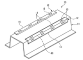
- FIG. 1 is a perspective view of a joint structure according to an embodiment of the present invention.
- FIG. 2A is a perspective view of a modification of the joint structure according to the embodiment of the present invention.
- FIG. 2B is a sectional view taken along line AA of FIG. 2A.
- FIG. 3 is a perspective view of the joint structure bent along the line BB in FIG. 2A.
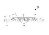
- FIG. 4 is a cross-sectional view of another modified example of the joint structure according to the embodiment of the present invention.
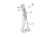
- FIG. 5 is a perspective view showing an example of a B pillar manufactured by hot stamping the joint structure according to the embodiment of the present invention.
- FIG. 6 is a perspective view showing another example of the B pillar manufactured by hot stamping the joint structure according to the embodiment of the present invention.
- FIG. 1 is a perspective view of a joint structure manufactured by the method for manufacturing a joint structure according to the present embodiment.
- the joint structure 10 includes a first plate-shaped member 11 made of steel, and a steel-made first plate-shaped member 11 formed as an elongated member narrower than the first plate-shaped member 11.
- both edges 12a along the longitudinal direction (X direction in the figure) of the second plate member 12 and the surface 11a of the first plate member 11 are formed by arc welding or laser-arc hybrid welding. They are joined by a metal (bead) 13.
- the weld metal (bead) 13 may be formed continuously along the both edges 12a or may be formed intermittently. However, as described later, when bending is performed along a virtual line B (see FIG. 2A) set on the overlapping surface 14, welding is performed to cope with the stress generated at the time of bending.
- the metal (bead) 13 is preferably formed continuously.
- the material of the first plate-like member 11 and the second plate-like member 12 made of steel is not particularly limited as long as it is pure iron and an iron alloy. For example, mild steel, carbon steel, stainless steel And so on.
- the first plate-like member 11 and the second plate-like member 12 are subjected to a surface treatment for forming a film such as an electric base element, a processed product, an insulating material, and a passivation for the purpose of preventing rust and the like. You can also. Examples include zinc plating, chromium plating, nickel plating, aluminum plating, tin (tin) plating, resin coating, and ceramic coating.
- Both edges 12a of the second plate-shaped member 12 and the surface 11a of the first plate-shaped member 11 are joined by a filler metal (welding wire) by arc welding or laser-arc hybrid welding. Therefore, for example, both edges 12a of the second plate-shaped member 12 can be joined with a wider area than when joining by spot welding, laser welding, or the like, and the joining strength is improved.
- a generally used welding wire or welding rod can be used as long as the welding metal 13 is an Fe-based alloy.
- the laser-arc hybrid welding is obtained by adding a laser as a heat source to an arc welding method as a heat source and a wire supply method. This method is advantageous in that the welding speed is higher than the ordinary arc welding method.
- both edges 12 a along the longitudinal direction of the second plate-shaped member 12 are welded to the first plate-shaped member 11 by arc welding or laser-arc hybrid welding.
- the edge 12b of the two plate-shaped member 12 extending in the direction intersecting both edges 12a (transverse direction) may also be welded to the first plate-shaped member 11 by arc welding or laser-arc hybrid welding.
- the first plate-like member 11 and the second plate-like member 12 welded by arc welding or laser-arc hybrid welding may be bent to form a molded product.
- Strength or bending strength may be insufficient.
- the width of the second plate-shaped member 12 is large and the distance between both edges 12a is large, there is a concern about insufficient strength.
- FIG. 2A shows that the surface 11a of the first plate-shaped member 11 and both edges 12a of the second plate-shaped member 12 are joined by arc welding or laser-arc hybrid welding
- the first plate-shaped member 11 and the FIG. 10 is a perspective view of a joint structure 10A according to a modified example in which overlapping surfaces 14 with two plate members 12 are joined by laser welding.
- FIG. 2B is a sectional view taken along line AA of FIG. 2A.
- a joint structure 10A has a first plate in which both edges 12a are joined to the first plate-like member 11 by arc welding or laser-arc hybrid welding.
- the superposed surfaces 14 of the plate-like member 11 and the second plate-like member 12 are along the longitudinal direction (X direction in FIG. 2A) of the second plate-like member 12 by laser welding, and 12 are joined by a plurality of pairs of joining portions 15 formed facing each other in the width direction. Thereby, the joining strength between the first plate member 11 and the second plate member 12 is further improved.
- the joint structure 10A thus formed is bent along the imaginary line B (see FIG. 2A) set on the overlapping surface 14, and the bent portion 16 is formed. It is processed into the molded product 20 shown.
- the bent portion 16 (the imaginary line B) is set so as to pass through substantially the center of the pair of joining portions 15 formed to face each other in the width direction of the second plate-shaped member 12. As a result, the force acting at the time of bending is applied equally to the left and right, and the shape accuracy of the molded product 20 is improved.
- a shearing force acts on the joint between the first plate-shaped member 11 and the second plate-shaped member 12.
- first plate-like member 11 and the second plate-like member 12 are joined only by spot welding or laser welding, joining with the first plate-like member 11 at the edge 12a of the second plate-like member 12
- the strength may be weak, and the second plate-like member 12 may peel off from the edge 12a.
- the first plate-like member 11 and the second plate-like member 12 are joined by welding both edges 12a of the second plate-like member 12 by arc welding or laser-arc hybrid welding. Further, the overlapping surfaces 14 of the first plate-shaped member 11 and the second plate-shaped member 12 are joined at a plurality of positions by laser welding. Accordingly, the bonding strength is high, and the first plate-like member 11 and the second plate-like member 12 are prevented from peeling off due to bending.
- the first plate-like member 11 and the second plate-like member 12 are, for example, steel materials for hot stamping. It is preferred to use.
- the joining structures 10 and 10A are made of a steel material for hot stamping, bending is performed by hot stamping (hot working) that is performed while being heated to a temperature of 800 ° C or higher. This enables accurate molding.
- FIG. 4 shows that the overlapping surfaces 14 of the first plate-like member 11 and the second plate-like member 12 whose edges 12a are joined by arc welding or laser-arc hybrid welding are formed by plasma welding, TIG welding, or laser welding.
- -It is sectional drawing of the joining structure which concerns on another modification joined by TIG hybrid welding.
- both edges 12a of the first plate-shaped member 11 and the second plate-shaped member 12 are joined with a weld metal 13 by arc welding or laser-arc hybrid welding.
- the overlapping surfaces 14 of the plate-like member 11 and the second plate-like member 12 are firmly joined at a plurality of locations by a joint 17 by plasma welding, TIG welding, or laser / TIG hybrid welding.
- both edges 12a of the first plate-shaped member 11 and the second plate-shaped member 12 are joined to the first plate-shaped member 11 by arc welding or laser-arc hybrid welding. Since the overlapping surfaces 14 of the member 11 and the second plate-like member 12 are firmly joined at any of a plurality of locations by any of laser welding, plasma welding, TIG welding, and laser / TIG hybrid welding, hot stamping is performed. And can be suitably used as structural members for automobiles.
- the laser / TIG hybrid welding is obtained by adding a laser as a heat source to a TIG welding method as a heat source and a wire supply method. This method is advantageous in that it has a deeper penetration (penetration between two plates) and a higher welding speed than the ordinary TIG welding method.
- FIG. 5 shows an example of a B pillar 30 (an example of a structural member for an automobile) manufactured by processing the joint structures 10, 10A, and 10B by hot stamping.
- the B pillar 30 is formed by joining a single second plate-shaped member 12 to a portion of the first plate-shaped member 11 where reinforcement is required by welding, and then integrally molding the same with a hot stamp.
- the two second plate-like members 12 are joined to the first plate-like member 11 at positions that become ridges of the B pillar 30, respectively.
- the second plate member 12 is formed by bending using a hot stamp on the overlapping surface 14.
- the present invention is not limited to the above-described embodiments and modified examples, and can be appropriately modified, improved, and the like.
- first plate-shaped member and the second plate-shaped member are further joined to each other within a plane of superposition of the first plate-shaped member and the second plate-shaped member (1).
- second plate-shaped member (1).
- the first plate-shaped member and the second plate-shaped member can be more firmly joined.
- the joining structure can be formed from an ultra-high strength steel plate.
- joint structure according to any one of (1) to (4), wherein the joint structure is an automobile structural member. According to this configuration, a joint structure that can be used as a structural member for an automobile can be manufactured.
- the first plate-like member and the second plate-like member may be laser-welded, plasma-welded, TIG-welded, and the like in a plane where the first plate-like member and the second plate-like member overlap.
- the joining structure can be formed from an ultra-high strength steel plate.
- First plate member (steel material for hot stamping) 11a Surface 12 Second plate member (steel material for hot stamping) 12a, 12b Edge 13 Weld metal (bead) 14 Overlapping surface 15 Joining section 16 Bending section 17 Joining section 20 Molded product (automobile structural member) 30 B pillar
Landscapes
- Engineering & Computer Science (AREA)
- Physics & Mathematics (AREA)
- Mechanical Engineering (AREA)
- Optics & Photonics (AREA)
- Plasma & Fusion (AREA)
- Chemical & Material Sciences (AREA)
- Combustion & Propulsion (AREA)
- Transportation (AREA)
- Body Structure For Vehicles (AREA)
- Laser Beam Processing (AREA)
- Arc Welding In General (AREA)
- Butt Welding And Welding Of Specific Article (AREA)
Abstract
La présente invention concerne une structure de jonction qui présente une résistance de jonction élevée et peut être fabriquée à faible coût, et un procédé de fabrication de la structure de jonction. L' invention concerne une structure de jonction dans laquelle sont assemblés un premier élément en forme de plaque en acier et un deuxième élément en forme de plaque en acier qui chevauche le premier élément en forme de plaque et est formée sous une forme allongée, la surface du premier élément en forme de plaque et les deux parties de bord le long de la direction longitudinale du deuxième élément en forme de plaque étant assemblées par un métal de soudage.
Priority Applications (5)
| Application Number | Priority Date | Filing Date | Title |
|---|---|---|---|
| EP19825575.4A EP3797913B1 (fr) | 2018-06-29 | 2019-05-31 | Structure de jonction et son procédé de fabrication |
| ES19825575T ES2970634T3 (es) | 2018-06-29 | 2019-05-31 | Estructura de unión y método para fabricar la misma |
| CN201980040804.5A CN112313026A (zh) | 2018-06-29 | 2019-05-31 | 接合结构体及其制造方法 |
| US17/256,499 US20210276126A1 (en) | 2018-06-29 | 2019-05-31 | Joining structure and method for manufacturing same |
| US18/323,903 US20230294205A1 (en) | 2018-06-29 | 2023-05-25 | Joining structure and method for manufacturing same |
Applications Claiming Priority (2)
| Application Number | Priority Date | Filing Date | Title |
|---|---|---|---|
| JP2018-124515 | 2018-06-29 | ||
| JP2018124515A JP7181016B2 (ja) | 2018-06-29 | 2018-06-29 | 接合構造体及びその製造方法 |
Related Child Applications (2)
| Application Number | Title | Priority Date | Filing Date |
|---|---|---|---|
| US17/256,499 A-371-Of-International US20210276126A1 (en) | 2018-06-29 | 2019-05-31 | Joining structure and method for manufacturing same |
| US18/323,903 Division US20230294205A1 (en) | 2018-06-29 | 2023-05-25 | Joining structure and method for manufacturing same |
Publications (1)
| Publication Number | Publication Date |
|---|---|
| WO2020003900A1 true WO2020003900A1 (fr) | 2020-01-02 |
Family
ID=68985008
Family Applications (1)
| Application Number | Title | Priority Date | Filing Date |
|---|---|---|---|
| PCT/JP2019/021881 Ceased WO2020003900A1 (fr) | 2018-06-29 | 2019-05-31 | Structure de jonction et son procédé de fabrication |
Country Status (6)
| Country | Link |
|---|---|
| US (2) | US20210276126A1 (fr) |
| EP (1) | EP3797913B1 (fr) |
| JP (1) | JP7181016B2 (fr) |
| CN (1) | CN112313026A (fr) |
| ES (1) | ES2970634T3 (fr) |
| WO (1) | WO2020003900A1 (fr) |
Cited By (4)
| Publication number | Priority date | Publication date | Assignee | Title |
|---|---|---|---|---|
| WO2022171665A1 (fr) | 2021-02-11 | 2022-08-18 | Autotech Engineering S.L. | Éléments structuraux pour un véhicule et procédés |
| CN115279507A (zh) * | 2020-03-16 | 2022-11-01 | 日本制铁株式会社 | 钢部件及其制造方法 |
| CN116323029A (zh) * | 2020-10-12 | 2023-06-23 | 日本制铁株式会社 | 长条构造构件及坯件 |
| RU2844187C2 (ru) * | 2021-02-11 | 2025-07-28 | Аутотек Инжиниринг С.Л. | Конструктивный элемент транспортного средства и способ изготовления конструктивного элемента |
Families Citing this family (5)
| Publication number | Priority date | Publication date | Assignee | Title |
|---|---|---|---|---|
| US11351590B2 (en) | 2017-08-10 | 2022-06-07 | Honda Motor Co., Ltd. | Features of dissimilar material-reinforced blanks and extrusions for forming |
| US10532421B2 (en) * | 2017-08-29 | 2020-01-14 | Honda Motor Co., Ltd. | UAM resistance spot weld joint transition for multimaterial automotive structures |
| US10870166B2 (en) | 2018-02-01 | 2020-12-22 | Honda Motor Co., Ltd. | UAM transition for fusion welding of dissimilar metal parts |
| US11465390B2 (en) | 2020-03-02 | 2022-10-11 | Honda Motor Co., Ltd. | Post-process interface development for metal-matrix composites |
| US20250129811A1 (en) * | 2023-10-24 | 2025-04-24 | GM Global Technology Operations LLC | Weldment assembly |
Citations (6)
| Publication number | Priority date | Publication date | Assignee | Title |
|---|---|---|---|---|
| JP2001507993A (ja) | 1997-01-14 | 2001-06-19 | コスマ パワーレーザーズ リミテッド | テイラードブランク |
| JP2002160020A (ja) * | 2000-11-28 | 2002-06-04 | Sumitomo Metal Ind Ltd | 自動車車体用接合金属帯およびその製造法 |
| JP2013220445A (ja) * | 2012-04-17 | 2013-10-28 | Nippon Steel & Sumitomo Metal Corp | ホットスタンプ用のテーラードブランクとその製造方法 |
| JP2014015206A (ja) | 2010-09-16 | 2014-01-30 | Nippon Steel & Sumitomo Metal | 成形部材およびその製造方法 |
| JP2017189781A (ja) * | 2016-04-11 | 2017-10-19 | 新日鐵住金株式会社 | テーラードブランク成形材 |
| JP2018124515A (ja) | 2017-02-03 | 2018-08-09 | Kddi株式会社 | コンピュータプログラム、端末および方法 |
Family Cites Families (27)
| Publication number | Priority date | Publication date | Assignee | Title |
|---|---|---|---|---|
| JPH10505791A (ja) * | 1994-09-23 | 1998-06-09 | フラウンホーファー−ゲゼルシャフト ツル フェルデルング デル アンゲヴァンテン フォルシュング エー ファウ | 工作物を溶接する方法 |
| US5603853A (en) * | 1995-02-28 | 1997-02-18 | The Twentyfirst Century Corporation | Method of high energy density radiation beam lap welding |
| JP3362624B2 (ja) * | 1997-01-10 | 2003-01-07 | 日本鋼管株式会社 | 重ね溶接継手の疲労特性向上方法 |
| JP2000197969A (ja) * | 1998-12-25 | 2000-07-18 | Sumitomo Metal Ind Ltd | 一体化成形用ブランクおよびその成形方法 |
| US20020003054A1 (en) * | 2000-07-10 | 2002-01-10 | Teruo Kamada | Vehicular body panel or component part and method for manufacturing same |
| DE10104468A1 (de) * | 2001-02-02 | 2002-08-29 | Eberspaecher J Gmbh & Co | Platine für ein Abgas-Gehäuseteil eines Kraftfahrzeugs sowie Verfahren zur Herstellung des Abgas-Gehäuseteils |
| JP2003268804A (ja) * | 2002-03-15 | 2003-09-25 | Hitachi Constr Mach Co Ltd | 建設機械の構成部材の補強装置及びその補強方法 |
| US7310878B2 (en) * | 2004-02-27 | 2007-12-25 | Gm Global Technology Operations, Inc. | Automotive lower body component method of manufacture |
| SE530228C2 (sv) * | 2006-08-25 | 2008-04-01 | Gestamp Hardtech Ab | Sätt att varmforma och härda en plåtdetalj, samt en B-stolpe till ett fordon |
| JP2011088484A (ja) * | 2009-10-20 | 2011-05-06 | Toyota Motor Corp | 車両用骨格部材及びその製造方法 |
| KR101710851B1 (ko) * | 2012-08-08 | 2017-02-27 | 신닛테츠스미킨 카부시키카이샤 | 중첩부의 용접 방법 및 겹침 용접 부재 |
| CN203649731U (zh) * | 2013-12-08 | 2014-06-18 | 中国石油天然气第一建设公司 | 一种储罐施工搭接板限位器 |
| US20150314363A1 (en) * | 2014-04-30 | 2015-11-05 | GM Global Technology Operations LLC | Method of forming a vehicle body structure from a pre-welded blank assembly |
| JP6168077B2 (ja) * | 2015-02-12 | 2017-07-26 | Jfeスチール株式会社 | プレス成形部品の接合構造、該接合構造を有する自動車用構造部品及び接合部品の製造方法 |
| KR101826491B1 (ko) * | 2015-02-13 | 2018-02-06 | 신닛테츠스미킨 카부시키카이샤 | 필릿 용접 조인트 및 그 제조 방법 |
| JP6065147B1 (ja) * | 2015-10-26 | 2017-01-25 | Jfeスチール株式会社 | 重ね隅肉アーク溶接継手、プレス成形部品の接合構造 |
| JP6544446B2 (ja) * | 2016-01-28 | 2019-07-17 | 日本製鉄株式会社 | 重ね溶接継手の疲労強度向上方法、重ね溶接継手の製造方法および重ね溶接継手 |
| US10011312B2 (en) * | 2016-06-08 | 2018-07-03 | Van-Rob Inc. | Process for forming reinforced rocker panel assembly |
| CA3029512A1 (fr) * | 2016-07-13 | 2018-01-18 | Nippon Steel & Sumitomo Metal Corporation | Produit moule par marquage a chaud, element structural l'utilisant et procede de fabrication d'un produit moule par marquage a chaud |
| JP2018075612A (ja) * | 2016-11-10 | 2018-05-17 | トヨタ自動車株式会社 | 曲げ加工部材及びその製造方法 |
| JP6553679B2 (ja) * | 2017-07-04 | 2019-07-31 | 東亜工業株式会社 | プレス成形品の製造方法 |
| JP6495383B2 (ja) * | 2017-07-04 | 2019-04-03 | 東亜工業株式会社 | プレス成形品の製造方法 |
| MX2020010274A (es) * | 2018-04-06 | 2020-11-06 | Nippon Steel Corp | Pieza en bruto superpuesta para estampado en caliente, metodo de fabricacion de cuerpo moldeado estampado en caliente superpuesto y cuerpo moldeado estampado en caliente superpuesto. |
| JP6950871B2 (ja) * | 2019-01-23 | 2021-10-13 | Jfeスチール株式会社 | 車体骨格部品 |
| JP7063930B2 (ja) * | 2020-03-13 | 2022-05-09 | フタバ産業株式会社 | 成形品の製造方法及び成形品 |
| JP7381965B2 (ja) * | 2020-03-16 | 2023-11-16 | 日本製鉄株式会社 | 鋼部品及びその製造方法 |
| EP4227015A4 (fr) * | 2020-10-12 | 2024-04-03 | Nippon Steel Corporation | Élément structural long et matériau d'ébauche |
-
2018
- 2018-06-29 JP JP2018124515A patent/JP7181016B2/ja active Active
-
2019
- 2019-05-31 US US17/256,499 patent/US20210276126A1/en active Pending
- 2019-05-31 ES ES19825575T patent/ES2970634T3/es active Active
- 2019-05-31 CN CN201980040804.5A patent/CN112313026A/zh active Pending
- 2019-05-31 WO PCT/JP2019/021881 patent/WO2020003900A1/fr not_active Ceased
- 2019-05-31 EP EP19825575.4A patent/EP3797913B1/fr active Active
-
2023
- 2023-05-25 US US18/323,903 patent/US20230294205A1/en active Pending
Patent Citations (6)
| Publication number | Priority date | Publication date | Assignee | Title |
|---|---|---|---|---|
| JP2001507993A (ja) | 1997-01-14 | 2001-06-19 | コスマ パワーレーザーズ リミテッド | テイラードブランク |
| JP2002160020A (ja) * | 2000-11-28 | 2002-06-04 | Sumitomo Metal Ind Ltd | 自動車車体用接合金属帯およびその製造法 |
| JP2014015206A (ja) | 2010-09-16 | 2014-01-30 | Nippon Steel & Sumitomo Metal | 成形部材およびその製造方法 |
| JP2013220445A (ja) * | 2012-04-17 | 2013-10-28 | Nippon Steel & Sumitomo Metal Corp | ホットスタンプ用のテーラードブランクとその製造方法 |
| JP2017189781A (ja) * | 2016-04-11 | 2017-10-19 | 新日鐵住金株式会社 | テーラードブランク成形材 |
| JP2018124515A (ja) | 2017-02-03 | 2018-08-09 | Kddi株式会社 | コンピュータプログラム、端末および方法 |
Cited By (7)
| Publication number | Priority date | Publication date | Assignee | Title |
|---|---|---|---|---|
| CN115279507A (zh) * | 2020-03-16 | 2022-11-01 | 日本制铁株式会社 | 钢部件及其制造方法 |
| US20230138581A1 (en) * | 2020-03-16 | 2023-05-04 | Nippon Steel Corporation | Steel component and production method for the same |
| EP4122617A4 (fr) * | 2020-03-16 | 2024-01-10 | Nippon Steel Corporation | Composant en acier et son procédé de fabrication |
| US12528110B2 (en) * | 2020-03-16 | 2026-01-20 | Nippon Steel Corporation | Steel component and production method for the same |
| CN116323029A (zh) * | 2020-10-12 | 2023-06-23 | 日本制铁株式会社 | 长条构造构件及坯件 |
| WO2022171665A1 (fr) | 2021-02-11 | 2022-08-18 | Autotech Engineering S.L. | Éléments structuraux pour un véhicule et procédés |
| RU2844187C2 (ru) * | 2021-02-11 | 2025-07-28 | Аутотек Инжиниринг С.Л. | Конструктивный элемент транспортного средства и способ изготовления конструктивного элемента |
Also Published As
| Publication number | Publication date |
|---|---|
| EP3797913B1 (fr) | 2024-01-31 |
| EP3797913A4 (fr) | 2021-08-18 |
| EP3797913A1 (fr) | 2021-03-31 |
| US20230294205A1 (en) | 2023-09-21 |
| JP7181016B2 (ja) | 2022-11-30 |
| US20210276126A1 (en) | 2021-09-09 |
| JP2020001076A (ja) | 2020-01-09 |
| ES2970634T3 (es) | 2024-05-29 |
| CN112313026A (zh) | 2021-02-02 |
Similar Documents
| Publication | Publication Date | Title |
|---|---|---|
| JP7181016B2 (ja) | 接合構造体及びその製造方法 | |
| KR101710851B1 (ko) | 중첩부의 용접 방법 및 겹침 용접 부재 | |
| JP5071451B2 (ja) | 接合素材、接合品および自動車車体 | |
| JP6651308B2 (ja) | 構造体構成部材及び構造体構成部材を製造する方法 | |
| JP5955370B2 (ja) | 金属接合体の製造方法 | |
| JP6998513B2 (ja) | 接合構造 | |
| EP2911822B1 (fr) | Soudure laser avec apport de métal de pièces automobiles | |
| US12515273B2 (en) | Joint structure, automotive component, and joint structure manufacturing method | |
| KR20150121709A (ko) | 자동차용 구조 부재 및 그 제조 방법 | |
| WO2016103376A1 (fr) | Structure de jonction de matériaux différents et procédé de jonction de matériaux différents | |
| JP6000932B2 (ja) | 構造体の連結部材の製造方法 | |
| JP2020131226A (ja) | 長尺形状のプレス成形部材、及びその製造法 | |
| CN110114186A (zh) | 用于制造工件复合体的方法和工件复合体 | |
| JP2009000728A (ja) | 異種金属の接合方法及び接合構造 | |
| DE50303409D1 (de) | Verfahren zum fügen zweier bleche einerseits aus einem aluminiumwerkstoff und anderseits aus einem eisen- oder titanwerkstoff durch eine schweiss-lötverbindung | |
| CN113165701B (zh) | 交叠的细长钢结构以及生产这种细长钢结构的方法 | |
| JP2023141116A (ja) | バッテリーケース及びバッテリーケースの製造方法 | |
| EP3978177A1 (fr) | Procédé de fabrication d'un complexe hétérométallique, et complexe hétérométallique | |
| JP6939468B2 (ja) | 車両構造材 | |
| JP7546208B2 (ja) | 接合構造 | |
| WO2019172025A1 (fr) | Structure de jonction et procédé de jonction | |
| JP2508388B2 (ja) | レ―ザ溶接方法 | |
| JP7807719B2 (ja) | スポット溶接構造、及びスポット溶接構造の製造方法 | |
| JP5027519B2 (ja) | 車体パネルの結合部の構造 | |
| JP6638983B2 (ja) | パイプ部品 |
Legal Events
| Date | Code | Title | Description |
|---|---|---|---|
| 121 | Ep: the epo has been informed by wipo that ep was designated in this application |
Ref document number: 19825575 Country of ref document: EP Kind code of ref document: A1 |
|
| NENP | Non-entry into the national phase |
Ref country code: DE |
|
| ENP | Entry into the national phase |
Ref document number: 2019825575 Country of ref document: EP Effective date: 20201222 |