WO2020003976A1 - Système d'évaluation musculaire - Google Patents
Système d'évaluation musculaire Download PDFInfo
- Publication number
- WO2020003976A1 WO2020003976A1 PCT/JP2019/022752 JP2019022752W WO2020003976A1 WO 2020003976 A1 WO2020003976 A1 WO 2020003976A1 JP 2019022752 W JP2019022752 W JP 2019022752W WO 2020003976 A1 WO2020003976 A1 WO 2020003976A1
- Authority
- WO
- WIPO (PCT)
- Prior art keywords
- signal
- test signal
- common mode
- bioelectrodes
- output
- Prior art date
- Legal status (The legal status is an assumption and is not a legal conclusion. Google has not performed a legal analysis and makes no representation as to the accuracy of the status listed.)
- Ceased
Links
Images


Classifications
-
- A—HUMAN NECESSITIES
- A61—MEDICAL OR VETERINARY SCIENCE; HYGIENE
- A61B—DIAGNOSIS; SURGERY; IDENTIFICATION
- A61B5/00—Measuring for diagnostic purposes; Identification of persons
- A61B5/24—Detecting, measuring or recording bioelectric or biomagnetic signals of the body or parts thereof
- A61B5/316—Modalities, i.e. specific diagnostic methods
- A61B5/389—Electromyography [EMG]
Definitions
- the present invention relates to a muscle evaluation system that evaluates a muscle activity state from a surface muscle action potential that appears on a bioelectrode that is in close contact with the body surface of a muscle, and more specifically, a bioelectrode that exhibits a surface muscle action potential and a body surface.
- the present invention relates to a muscle evaluation system that also determines a close contact state.
- a test signal is output from one of the bioelectrode and the common electrode, and a test signal of a predetermined level does not appear on the other.
- a muscle evaluation system that determines that a biological electrode is not in close contact with a body surface and transmits the determination result to a measurer.
- a test signal is alternately output from a set of bioelectrodes that are in close contact with the body surface, and the test signal is brought into close contact with the middle of the body surface where the set of bioelectrodes is in close contact.
- test signal of a predetermined level It is determined whether or not a test signal of a predetermined level appears on the common electrode. If a test signal of a predetermined level cannot be detected from the common electrode even when a test signal is output to any of the bioelectrodes, the bioelectrode is detected. It is determined that it does not adhere to the body surface.
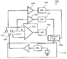
- the muscle evaluation system 100 disclosed in Patent Document 2 utilizes the inverting amplifier circuit 102 that amplifies and detects the surface muscle action potential, and detects the bioelectrodes 101+, It is possible to determine the close contact of 101-.
- the muscle evaluation system 100 will be described with reference to FIG. 1.
- a pair of bioelectrodes 101+ and 101 ⁇ that are in close contact with the muscle body surface are connected to a non-inverting input and an inverting input of an operational amplifier 102, respectively.
- a myoelectric signal hereinafter, referred to as an EMG signal
- EMG signal myoelectric signal of the difference between the surface muscle action potentials appearing between the pair of bioelectrodes 101+ and 101- is amplified by the operational amplifier 102 and output.
- the EMG signal output from the operational amplifier 102 is converted into a digital signal by an A / D converter 103 connected to the output side of the operational amplifier 102, and the activity of the muscle is controlled by a microprocessor (not shown) connected to the output side of the A / D converter 103. The condition is evaluated.
- a common electrode 104 is adhered to the vicinity of the body surface to which the pair of bioelectrodes 101+ and 101 ⁇ adhere, and a test signal is output from the test signal output circuit 110 to the common electrode 104 under the control of the clock / trigger circuit 109.
- the pair of bioelectrodes 101+ and 101 ⁇ are connected to the non-inverting input and the inverting input of the operational amplifier 102, and are connected to the amplifier circuits 105 and 106 that are separately configured from the operational amplifier 102, respectively.
- Outputs of the circuits 105 and 106 are A / D-converted by A / D converters 107 and 108 connected to outputs of the amplifier circuits 105 and 106, respectively, at a timing when the clock / trigger circuit 109 outputs a test signal.
- the A / D converters 107 and 108 perform A / D conversion at a timing when a test signal is output to the common electrode 104.
- the output test signal is output.
- the muscle evaluation system disclosed in Patent Document 1 outputs test signals alternately to one set of bioelectrodes in order to determine the closeness of one set of bioelectrodes to the body surface. It is necessary to connect the detection means for detecting the test signal separately from the detection means for detecting the surface muscle action potential appearing to the common electrode, and the signal of the test signal is compared with the surface muscle action potential appearing on a set of biological electrodes. Since the intensity is extremely high, it was not possible to simultaneously detect the surface muscle action potential and determine the close contact state of a set of biological electrodes.
- test signal is output alternately to a set of bioelectrodes to determine any bioelectrode that is not in close contact with the body surface
- output control of the test signal and detection control of the test signal are complicated.
- the amplifier circuits 105 and 106 and the A / D converters 107 and 108 are omitted, and the output of the operational amplifier 102 including the EMG signal of the surface muscle action potential includes the test signal at the output timing of the test signal.
- Another embodiment describes a muscle evaluation system that determines that the bioelectrodes 101+ and 101- are not in close contact with the body surface when they are not in contact. However, connecting the pair of bioelectrodes 101+ and 101- to the non-inverting input and the inverting input of the operational amplifier 102 appears on the pair of bioelectrodes 101+ and 101- by utilizing the common mode removal function of the operational amplifier 102.
- the inverting input and the non-inverting input of the operational amplifier 102 are intentionally unbalanced, and when one set of the bioelectrodes 101+ and 101- is normally in close contact with the body surface, the test signal is output. Appears in the output of the operational amplifier 102, and when a test signal of a predetermined signal voltage corresponding to the unbalance is not output, it is determined that the set of bioelectrodes 101+ and 101- is not in close contact with the body surface.
- the present invention has been made in view of such a conventional problem, and a differential amplifier circuit for detecting a surface muscle action potential is also used as a detection circuit for determining the close contact of a bioelectrode on a body surface. It is another object of the present invention to provide a muscle evaluation system capable of determining whether a bioelectrode is in close contact with a body surface even during detection of a surface muscle action potential.
- Another object of the present invention is to provide a muscle evaluation system capable of judging the close contact of each bioelectrode with the body surface without providing a detecting means for detecting a test signal for each set of bioelectrodes.
- the differential amplifier circuit that detects the surface muscle action potential is also used as a detection circuit that determines the adhesion of the bioelectrode to the body surface, the muscle that completely removes the common mode noise that appears on a set of bioelectrodes
- the purpose is to provide an evaluation system.
- the muscle evaluation system includes a pair of bioelectrodes exposed on a back surface of an insulating sheet facing a body surface, and a pair of bioelectrodes exposed to inverting input and non-inverting, respectively.
- a differential amplifier circuit that is connected to the input, amplifies the difference between the inverting input and the non-inverting input, and outputs the amplified signal.
- the surface appearing on the set of bioelectrodes in a state in which the set of bioelectrodes is in close contact with the body surface A muscle evaluation system that amplifies the difference between muscle action potentials and evaluates the activity of muscles in the body surface to which a set of bioelectrodes are in close contact from a myoelectric signal output from a differential amplifier circuit.
- a common electrode that is attached to and exposed to the body surface in the middle of a pair of biological electrodes, a test signal output unit that outputs a common mode test signal of a predetermined frequency to the common electrode, and a differential amplifier circuit.
- Predetermined frequency common mode If the signal strength of the common mode test signal extracted by the signal extracting means for extracting the strike signal and the common mode test signal extracted by the signal extracting means exceeds a predetermined allowable signal strength, it is determined that any of the bioelectrodes is not in close contact with the body surface. And a closeness determination unit that performs the determination.
- a differential amplifier circuit that connects an inverting input and a non-inverting input to a set of bioelectrodes Outputs a myoelectric signal obtained by amplifying the difference between the surface muscle action potentials appearing on a set of biological electrodes, and evaluates the muscle activity from the myoelectric signal.
- a common mode test signal with almost the same signal voltage and in-phase is output to the set of bioelectrodes.
- the output of the differential amplifier circuit has a very small signal strength less than a predetermined allowable signal strength. Output a common mode test signal.
- the signal extraction unit extracts a common mode test signal of a predetermined frequency from the output of the differential amplifier circuit on which the myoelectric signal is superimposed, and the adhesion determination unit determines that the signal intensity of the common mode test signal is equal to or less than the allowable signal intensity. Therefore, it is determined that one set of the biological electrodes is in close contact with the body surface.
- the contact determining means determines that any of the bioelectrodes is not in close contact with the body surface since the signal strength of the common mode test signal extracted by the signal extracting means exceeds the allowable signal strength.
- the signal strength of the common mode test signal extracted by the signal extraction means is equal to or less than the allowable signal strength
- the adhesion determination means determines the strength of the myoelectric signal output from the differential amplifier circuit.
- the signal strength of the common mode test signal extracted by the signal extraction means is equal to or less than the allowable signal strength, regardless of whether the set of bioelectrodes is in close contact with the body surface.
- the signal strength of the myoelectric signal representing the surface muscle action potential output from the differential amplifier circuit exceeds a predetermined signal strength threshold. Since the signal strength exceeds the threshold, the signal strength of the myoelectric signal is equal to or less than the predetermined signal strength threshold value, so that it can be determined that none of the bioelectrodes is in close contact with the body surface.
- the muscle evaluation system further comprising a phase comparison circuit that compares the phase of the common mode test signal extracted by the signal extraction unit with the phase of the common mode test signal output by the test signal output unit.
- a phase comparison circuit that compares the phase of the common mode test signal extracted by the signal extraction unit with the phase of the common mode test signal output by the test signal output unit.
- the common mode test signal input to the inverting input of the differential amplifier circuit is output from the differential amplifier circuit in the opposite phase to the common mode test signal output by the test signal output means, and is input to the non-inverting input.
- the signal is output from the differential amplifier circuit in the same phase as the common mode test signal output by the test signal output means. Therefore, when the phase of the common mode test signal extracted by the signal extraction means is in phase with the common mode test signal output by the test signal output means, the common mode test signal does not appear on the biological electrode connected to the inverting input, It is determined that the bioelectrode is not in close contact with the body surface.
- the phase of the common mode test signal extracted by the signal extraction unit is opposite to the common mode test signal output by the test signal output unit, the common mode test signal is displayed on the bioelectrode connected to the non-inverting input. Therefore, it is determined that the bioelectrode is not in close contact with the body surface.
- the adhesion determining means sets a common mode test output from the differential amplifier circuit using the output voltage of the differential amplifier circuit as a reference voltage when the inverting input and the non-inverting input are short-circuited.
- the signal voltage of the signal is equal to or higher than the upper limit voltage obtained by adding a predetermined allowable voltage error to the reference voltage
- the voltage is equal to or lower than the lower limit voltage obtained by subtracting the allowable voltage error from the reference voltage, it is determined that the other bioelectrode connected to the inverting input of the differential amplifier circuit is not in close contact with the body surface.
- the signal voltage of the common mode test signal output from the differential amplifier circuit is a voltage obtained by adding a reference voltage to a voltage obtained by amplifying a difference voltage between the common mode test signal input to the inverting input and the non-inverting input. In the state where the bioelectrode is in close contact with the body surface, no difference voltage is generated, so that the reference voltage is used.
- the adhesion determination unit determines It is determined that the other biological electrode connected to the inverting input is not in close contact with the body surface.
- the muscle evaluation system according to claim 5 is characterized in that the common electrode is exposed so as to protrude from the back surface of the insulating sheet from a set of living body electrodes.
- the common electrode that protrudes from the bioelectrode to the body surface also adheres to the body surface, and outputs a common mode test signal to the common electrode to adhere to the body surface.
- a common mode test signal appears on the living body electrode.
- the muscle evaluation system wherein the distance from the common electrode exposed on the back surface of the insulating sheet to each set of living electrodes is different, and the common electrode and one set of each living body are caused by the flow of the common mode test signal.
- the potential difference between the electrodes is set as an offset voltage of the differential amplifier circuit.
- the distance between the common electrode and each set of bioelectrodes is adjusted to generate a potential difference in the signal voltage of the common mode test signal appearing on the set of bioelectrodes, which is used as the offset voltage of the differential amplifier circuit.
- the differential amplifier circuit can amplify and output the difference between the inverting input and the non-inverting input with high precision without preparing a voltage power supply.
- the signal extracting means extracts a common mode test signal having a predetermined frequency from an output of the differential amplifier circuit including the myoelectric signal.
- a signal of a predetermined frequency is separated from the output of the differential amplifier circuit to extract a common mode test signal, and a set of It is determined whether or not the living body electrode is in close contact with the body surface.
- the first aspect of the present invention it is determined whether or not a set of bioelectrodes is in close contact with the body surface by using the common mode removal function of the differential amplifier circuit that detects surface muscle action potentials. There is no need to provide another detecting means for detecting the mode test signal.
- test signal output means outputs a common mode test signal of a predetermined frequency to the common electrode
- the myoelectric signal and the common mode test signal are superimposed on the output of the differential amplifier circuit, and the myoelectric signal is detected to detect the myoelectric signal. Even during the evaluation of the activity, it is possible to extract only the common mode test signal and determine the adhesion of the bioelectrode to the body surface from the signal strength of the extracted common mode test signal.
- the common mode noise that appears on the set of bioelectrodes while the set of bioelectrodes is in close contact with the body surface is removed from the output by the common mode rejection function of the differential amplifier circuit. From the unaffected myoelectric signals, it is possible to evaluate activities such as muscle fatigue status and increase / decrease in the number of mobilizations.
- a common mode test signal having a predetermined signal strength is output from the differential amplifier circuit. Any biological electrode that is not in close contact with the body surface can be determined from the phase.
- the second aspect of the present invention it is possible to determine a case where none of a set of biological electrodes is in close contact with the body surface.
- the phase of the common mode test signal extracted by the signal extraction unit and the phase of the common mode test signal output by the test signal output unit are compared, and any one of the set of bioelectrodes is brought into close contact with the body surface. You can determine whether or not.
- the fourth aspect of the invention it is possible to determine any of the bioelectrodes that are not in close contact with the body surface from the signal voltage of the common mode test signal output from the differential amplifier circuit without using the phase comparison circuit.
- the common mode test signal since the common mode test signal can be reliably transmitted to the living body electrode in close contact with the body surface, the common mode test signal does not flow from the common electrode to the body surface. Adhesion of a set of bioelectrodes to the body surface can be reliably determined without erroneous determination of the adhesion of the bioelectrode to the body surface.
- the inverting input and the differential amplifier circuit can be used.
- the difference between non-inverting inputs can be amplified and output with high precision.
- the close contact state of the bioelectrode on the body surface can be determined at the same time.
- the state in which the bioelectrode is separated from the body surface can be immediately detected.
- FIG. 9 is a cross-sectional view showing a state in which an insulating sheet 30 is adhered to a back surface 30 a of a body surface 51 of a streak 50. It is a block diagram of muscle evaluation system 20 concerning a 2nd embodiment.
- FIG. 2 is a block diagram of a differential amplifier circuit 21.
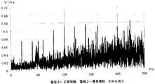
- FIG. 9 is a waveform diagram showing an output of the FFT analyzer 22 during a time when a pair of bioelectrodes 2+ and 2- closely adhere to the body surface 51 and the muscle 50 is arbitrarily contracted.
- FIG. 9 is a waveform diagram showing an output of the FFT analyzer 22 during a time when a pair of bioelectrodes 2+ and 2- closely adhere to the body surface 51 and the muscle 50 is arbitrarily contracted.
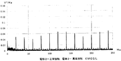
- FIG. 9 is a waveform diagram showing an output of the FFT analyzer 22 during a time when a pair of bioelectrodes 2+ and 2- closely adhere to the body surface 51 and the muscle 50 is not voluntarily contracted.
- FIG. 9 is a waveform diagram showing an output of the FFT analyzer 22 while the muscle 50 is arbitrarily contracted in a state where one of a pair of bioelectrodes 2+ and 2- is not in close contact with the body surface 51.
- FIG. 9 is a waveform diagram showing an output of the FFT analyzer 22 while the muscle 50 is not arbitrarily contracted in a state where one of a pair of bioelectrodes 2+ and 2- is not in close contact with the body surface 51.
- It is a block diagram showing the conventional muscle evaluation system 100.
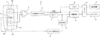
- the muscle evaluation system 1 includes a set of bioelectrodes 2+ and 2- that make a muscle action potential propagated along a muscle fiber of the muscle 50 when the muscle 50 voluntarily contracts close to a body surface 51 of the muscle 50.
- the abnormalities and fatigue of the muscle 50 are evaluated from the detected and amplified myoelectric signals (hereinafter referred to as EMG signals) in which the muscle action potentials are continuous, and a set of bioelectrodes 2+ and 2- is attached to the body surface 51.
- EMG signals detected and amplified myoelectric signals
- a close determination is made as to whether or not there is close contact.
- the bioelectrode 2 is in close contact with the body surface 51 means that the bioelectrode 2 and the body surface 51 are low enough that a muscle action potential sufficient to evaluate the state of the muscle 50 appears on the bioelectrode 2.
- the state of contact with contact resistance is referred to as normal contact.
- the state of close contact is referred to as normal contact, and the state where muscle action potential sufficient to evaluate the state of muscle 50 does not appear on bioelectrode 2 is referred to as abnormal contact. That.
- a pair of bioelectrodes 2+ and 2- are attached to both sides of the elongated insulating sheet 30 in the longitudinal direction so as to be in close contact with the body surface 51 along the muscle fibers of the muscle 50.
- the electrode surface is exposed on the back surface 30a on the side opposite to.
- a pair of bioelectrodes 2+ and 2- are connected to a non-inverting input 5+ and an inverting input 5- of an operational amplifier 5 constituting a differential amplifier circuit, respectively.
- the difference between the action potential and the potential of a common mode test signal described later is amplified and output. Therefore, the operational amplifier 5 has a common mode elimination function of removing, from its output, signals input to the non-inverting input 5+ and the inverting input 5- at the same phase and at the same level.
- a common electrode 4 to which a common mode test signal is output from the test signal output circuit 3 is mounted in the middle of the one set of the bioelectrodes 2+ and 2 ⁇ mounted on the insulating sheet 30.
- the electrode surface of the common electrode 4 is also exposed on the back surface 30 a of the insulating sheet 30, and the exposed position is adjusted according to the offset voltage Vos of the operational amplifier 5. That is, the distance between the common electrode 4 and the living body electrode 2+, which is in close contact with the body surface 51, and the distance between the common electrode 4 and the living body electrode 2 are made slightly different, so that the impedance between the common mode test signal flows is made different.
- the exposed position of the common electrode 4 is set so that the potential difference of the common mode test signal appearing at each of the bioelectrodes 2+, 2- coincides with the potential difference corresponding to the offset voltage Vos of the operational amplifier 5. To either side. As a result, the difference between the muscle action potential and the common mode test signal input to the non-inverting input 5+ and the inverting input 5- of the operational amplifier 5 is amplified and output without being affected by the internal error of the operational amplifier 5. .
- the common electrode 4 is thicker than the pair of bioelectrodes 2+, 2-, and further projects downward from the position where the pair of bioelectrodes 2+, 2-exposes on the back surface 30a of the insulating sheet 30 as shown in FIG. Then, it is brought into contact with the body surface 51 pushed inward.
- the signal strength of the common mode test signal appearing on the pair of bioelectrodes 2+ and 2- The state of contact with the body surface 51 can be determined.
- the test signal output circuit 3 outputs a common mode test signal of a voltage and a current that does not give a stimulus to a subject.
- a current of about 150 nA flows.
- the common mode test signal is output to the common electrode 4.
- the frequency of the common mode test signal is set to a predetermined frequency so that it can be detected from a signal appearing on the pair of bioelectrodes 2+ and 2-. In this case, the muscle generated when the muscle 50 contracts voluntarily.
- the EMG signal detected from the action potential is approximately 1 kHz or less, and the common mode test signal is also passed through the biological signal filter 6 that passes the EMG signal.
- the frequency is set to 20 Hz so that it can be identified and extracted.
- the biological signal filter 6 connected to the output of the operational amplifier 5 allows the output signal including the EMG signal having a frequency of 1 kHz or less and the output signal including the common mode test signal to pass from the output signal of the operational amplifier 5, and the logger 8 and the contact determination circuit. It outputs to the 9 and 20 Hz bandpass filters 7.
- the EMG signal output from the biological signal filter 6 is a signal output from the operational amplifier 5 having a common mode elimination function.
- the muscle action potential propagates along the muscle fiber of the muscle 50, and a set of biological signals is generated.
- the muscle action potentials having different phases appear on the electrodes 2+ and 2-, and are input to the non-inverting input 5+ and the inverting input 5- of the operational amplifier 5, so that the operational amplifier 5 amplifies the difference between the muscle action potentials having different phases.
- An EMG signal is output.
- the logger 8 records the EMG signal obtained by amplifying the difference between the muscle action potentials output from the biological signal filter 6 together with the elapsed time, and outputs the EMG signal to the microcomputer 10.
- the frequency, amplitude and changes in the EMG signal depend on the contractile activity of the muscle 50. For example, when the fatigue of the voluntarily contracting muscle 50 is increased, the number of mobilized motor units and the firing frequency for supplementing the contractility of the muscle 50 are reduced.
- the microcomputer 10 evaluates various activities of the muscle 50 from changes in the EMG signal input from the logger 8 and the elapsed time.
- a display device 11 and a speaker 12 are connected to the microcomputer 10, and the evaluation result of the streak 50 evaluated by the microcomputer 10 is displayed on the display device 11 and / or a sound emitted from the speaker 12 to use the streak evaluation system 1.
- the microcomputer 10 evaluates, the speaker 12 emits a voice prompting to stop the contraction movement of the muscle 50.
- the bandpass filter 7 further allows a signal of 20 Hz to pass from the output of the biological signal filter 6 to extract a common mode test signal, and outputs it to the phase comparison circuit 13 and the contact determination circuit 9.
- the phase circuit 9 compares the common mode test signal output from the bandpass filter 7 with the output timing of the common mode test signal from the test signal output circuit 3 and has the same phase as the common mode test signal output from the test signal output circuit 3. And whether the phases are reversed.
- the bioelectrode 2 connected to the inverting input 5 of the operational amplifier 5 is not in close contact with the body surface 51 of the set of bioelectrodes 2+ and 2-, the common mode test signal appearing on the bioelectrode 2+ Exceeds the inverting input 5 and is input to the non-inverting input 5+, so that the common mode test signal included in the output of the operational amplifier 5 is in phase with the common mode test signal output from the test signal output circuit 3, and the phase comparison is performed.
- the circuit 13 outputs the in-phase comparison result to the contact determination circuit 9.
- the phase comparison circuit 13 outputs a comparison result having an opposite phase to the contact determination circuit 9.
- the contact determination circuit 9 determines a set of each bioelectrode from the EMG signal output from the biological signal filter 6, the common mode test signal output from the bandpass filter 7, and the comparison result output from the phase comparison circuit 13. The contact state of the contact determination circuit 9 is determined in detail below.
- the contact determination circuit 9 determines that the signal strength of the common mode test signal output from the bandpass filter 7 is equal to or less than a predetermined allowable signal strength. Since the EMG signal output from the biological signal filter 6 exceeds a predetermined signal strength threshold value, it is determined that both of the pair of biological electrodes 2+ and 2- are in normal contact.
- the muscle action potential does not appear in the set of bioelectrodes 2+ and 2-, and is not input to the non-inverting input 5+ and the inverting input 5- of the operational amplifier 5, so that the EMG signal output from the biosignal filter 6 is If the signal strength of the common mode test signal output from the bandpass filter 7 is equal to or less than a predetermined allowable signal strength and the EMG signal output from the biological signal filter 6 is also a predetermined signal, Since the intensity is equal to or less than the intensity threshold value, it is determined that any of the pair of biological electrodes 2+ and 2- is abnormal contact.
- the contact determination circuit 9 It is determined that the bioelectrode 2+ connected to the non-inverting input 5+ is in normal contact and the bioelectrode 2- connected to the inverting input 5 is in non-contact.
- the signal strength of the common mode test signal output from the bandpass filter 7 exceeds a predetermined allowable signal strength and the comparison result of the opposite phase is input from the phase comparison circuit 13
- the bioelectrode 2- connected to the inverting input of the operational amplifier 5 is in normal contact, and the bioelectrode 2+ connected to the non-inverting input 5+ is non-contact.
- the common mode test signal output from the operational amplifier 5 Is set to a reference voltage, for example, 1 / the signal voltage of the common mode test signal input to the operational amplifier 5 when the output voltage of the operational amplifier 5 when the inverting input 5 ⁇ and the non-inverting input 5+ are short-circuited is used as the reference voltage.
- the bioelectrode 2+ connected to the non-inverting input 5+ of the operational amplifier 5 makes abnormal contact
- the bioelectrode 2- connected to the inverting input 5 makes normal contact.
- the voltage is equal to or lower than the lower limit voltage obtained by subtracting the allowable voltage error from the reference voltage. Therefore, when the signal strength of the common mode test signal output from the bandpass filter 7 exceeds a predetermined allowable signal strength and one of the pair of bioelectrodes 2+ and 2- is in normal contact, the contact determination circuit 9 is also used to compare whether the signal voltage of the common mode test signal output from the bandpass filter 7 is equal to or higher than the upper limit voltage or equal to or lower than the lower limit voltage without using the comparison result of the phase comparison circuit 13. Which of the biological electrodes 2+ and 2- is abnormal contact can be determined.
- the contact determination circuit 9 determines that one or both of the pair of bioelectrodes 2+ and 2- is abnormal contact
- the contact determination circuit 9 outputs the determination result to the microcomputer 10, and the microcomputer 10 displays the determination result indicating the abnormal contact.
- the information is transmitted to the user by a display on the device 11 and / or a sound emitted from the speaker 12. Therefore, the set of bioelectrodes 2+, 2- is brought into close contact with the body surface 51 of the muscle 50, and the abnormalities of the bioelectrodes 2+, 2- are evaluated before the muscle 50 is evaluated from the EMG signal or during the exercise of voluntarily contracting the muscle 50. Contact can be transmitted to the user, and re-adhesion of the bioelectrodes 2+ and 2- can be promoted.
- a muscle evaluation system 20 according to the second embodiment of the present invention will be described with reference to FIGS.
- the components of the muscle evaluation system 20 that have the same or similar functions as those of the muscle evaluation system 1 described above, the detailed description thereof will be omitted using the same reference numerals.
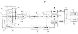
- This muscle evaluation system 20 also provides a muscle action potential transmitted along the muscle fibers of the muscle 50 when the muscle 50 voluntarily contracts from a set of bioelectrodes 2+ and 2- Unlike the muscle evaluation system 1, the pair of bioelectrodes 2 + and 2-and the common electrode 4 whose electrode surfaces are exposed on the back surface 30 a of the insulating sheet 30 are connected to the non-inverting input 21 + and the inverting input 21-, respectively. , A differential amplifier circuit 21 connected to the ref input 21R, an AD converter 23 for A / D converting an analog output of the differential amplifier circuit 21, and an EMG signal of the differential amplifier circuit 21 A / D converted by the AD converter 23. And an FFT analyzer 22 that performs a fast Fourier transform on an output signal including the common mode test signal and calculates a signal strength for each frequency.
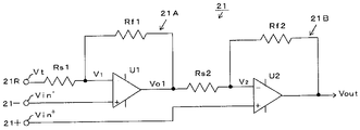
- the differential amplifier circuit 21 includes a first non-inverting amplifier circuit 21A and a second non-inverting amplifier circuit 21B in which an output of the first non-inverting amplifier circuit 21A is connected to an inverting input via a second input resistor Rs2. As shown in FIG. 4, the non-inverting input 21+ and the inverting input 21- of the differential amplifier circuit 21 are connected to the non-inverting inputs of the second operational amplifier U2 and the first operational amplifier U1, respectively. potential appearing 2 to Vin + and Vin - a second operational amplifier U2 respectively are input to the non-inverting input of the first operational amplifier U1.
- the ref input 21R of the differential amplifier circuit 21 connected to the common electrode 4 is connected to the inverting input of the first operational amplifier U1 via the inverting input resistor Rs1, and the signal of the common mode test signal output to the common electrode 4 is output.
- the voltage Vt is input to the inverting input of the first operational amplifier U1.
- the ratio of the resistance value of the first feedback resistor Rf1 to the first input resistor Rs1 of the first non-inverting amplifier circuit 21A is k
- the ratio of the resistance value of the second non-inverting amplifier circuit 21B to the second input resistor Rs2 is k.
- the ratio of the resistance value of the second feedback resistor Rf2 is 1 / k, which is the reciprocal of the above ratio.
- the differential amplifier circuit 21 removes a common mode rejection signal in which Vin + and Vin ⁇ input to the non-inverting input 21+ and the inverting input 21 ⁇ in the same phase have the same level.
- the signal voltage Vt of the common mode test signal to be input to the ref input 21R, a pair of bioelectrode 2 +, the potential Vin + appearing in 2-Vin - was amplified in the difference in (1 + k) / k
- the output signal to which the voltage is applied is output to the biological signal filter 6.
- the voltage gain A of the differential amplifier circuit 21 represented by (1 + k) / k is set to 1000, and the difference between the signal voltages of the common mode test signals appearing in the pair of bioelectrodes 2+ and 2- is obtained. , 0.2 mV, the differential amplifier 21 outputs a common mode test signal having a signal voltage of 200 mV.
- the biological signal filter 6 connected to the output of the differential amplifier circuit 21 passes an output signal including an EMG signal having a frequency of 1 kHz or less and a common mode test signal from the output signal of the differential amplifier circuit 21 and connects to the output side.
- a / D conversion is performed by the A / D converter 23, and the digital signal is calculated by the FFT analyzer 22.
- the output signal which is a digital signal output from the AD converter 23 includes an EMG signal and a common mode test signal
- the common mode test signal includes a ref input 21R as shown in Expression (3).
- Both the input common mode test signal and the common mode test signal obtained by amplifying the difference between the signal voltages of the common mode test signals appearing on each set of the biological electrodes 2+ and 2- by 1000 times are included.
- the difference between the common mode test signals appearing on the set of bioelectrodes 2+ and 2- is 0 or a small value, and the difference between the pair of bioelectrodes 2+ and 2- Any common mode test signal is negligible compared to the EMG signal output from the AD converter 23 by amplifying the difference of the appearing EMG signal by 1000 times. Sai.
- the output signal A / D-converted by the AD converter 23 can be regarded as representing the EMG signal as it is, and is temporarily stored in the logger 8.
- the microcomputer 10 evaluates the activity of the muscle 50 from the EMG signal stored in the logger 8 and transmits the result to the user via the display device 11 or the speaker 12.
- the microcomputer 10 receives a determination result from the contact determination circuit 9 that at least one of the pair of bioelectrodes 2+ and 2- is in abnormal contact as described later, the AD stored in the logger 8 is detected. Since the output signal of converter 23 includes a common mode test signal that cannot be ignored, it is not regarded as an EMG signal, and the activity of muscle 50 is not evaluated from the output signal.
- the output signal of the AD converter 23 is also output to the FFT analyzer 22 and the phase comparison circuit 13, and the FFT analyzer 22 performs a fast Fourier transform on the output signal of the AD converter 23 in a band including the EMG signal and the common mode test signal,
- the signal strength for each frequency is calculated, and the signal strength calculated for the common mode test signal of 20 Hz is output to the contact determination circuit 9.
- the FFT analyzer 22 expresses the signal strength for each frequency of the output signal of the AD converter 23 with the power value calculated by the square of the signal voltage per unit frequency width (1 Hz width), and the FFT analyzer 22 calculates for 20 Hz.
- the power value is used as the signal strength of the common mode test signal
- the signal power or signal voltage of the common mode test signal of 20 Hz output from the AD converter 23 may be used as the signal strength of the common mode test signal.
- the FFT analyzer 22 since the FFT analyzer 22 also calculates the signal strength of each frequency of the EMG signal, the FFT analyzer 22 outputs the calculation result to the logger 8 or the microcomputer 10, and the microcomputer 10 calculates the signal strength from the signal strength of each frequency of the EMG signal. , The activity of muscle 50 can also be evaluated.
- the common mode test signal output from the AD converter 23 includes the common mode test signal input to the ref input 21R of the differential amplifier circuit 21 as shown in Expression (3). Even if the respective biological electrodes 2+ and 2- are in normal contact, the signal strength of the 20 Hz common mode test signal output from the FFT analyzer 22 does not become zero. Further, even if the bioelectrodes 2+ and 2- are not completely in contact with the body surface 51, a signal intensity capable of evaluating the activity of the muscle 50 is detected from the signal level of the common mode test signal appearing on the bioelectrodes 2+ and 2-.
- the contact determination circuit 9 sets a predetermined allowable signal strength, and sets any one of them only when the signal strength of the common mode test signal of 20 Hz output from the FFT analyzer 22 exceeds this allowable signal strength. Are determined to be abnormal contacts.
- the contact determination circuit 9 determines that one of the set of bioelectrodes 2+ and 2- The other is determined to be abnormal contact, and it is determined which one is abnormal by referring to the phase determination result of the phase comparison circuit 13.
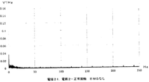
- FIG. 6 shows a state where a common mode test signal of 20 Hz and 0.3 mV is output from the test signal output circuit 3 and the pair of bioelectrodes 2+ and 2- are in normal contact without arbitrarily contracting the muscle 50.
- FIG. 4 is an output diagram output from the FFT analyzer 22 of FIG. 5.
- the signal strength of the 20 Hz common mode test signal calculated by the FFT analyzer 22 by the common mode removal function of the differential amplifier circuit 21 is 0.0017 V 2 / Hz. Has become.
- FIG. 8 showing an output diagram output from the FFT analyzer 22 under the same condition and one set of one of the biological electrodes 2 is in abnormal contact, a signal of 20 Hz and its multiple appear remarkably.
- FIG. 5 shows the output diagram of FIG. 6 showing the output of the FFT analyzer 22 in a state where the pair of bioelectrodes 2+ and 2- normally contact each other under the same conditions as in FIG.
- the muscle 50 voluntarily contracts, one of the pair of bioelectrodes 2+ and 2 ⁇ is erroneously determined to be an abnormal contact.
- the voltage becomes 0.0489 V 2 / Hz or more, and when any one of the pair of bioelectrodes 2+, 2- comes into normal contact, the voltage becomes 0.0169 V 2 / Hz or less. If the allowable signal strength is set during this time, even if the muscle 50 is arbitrarily contracted, it is possible to determine abnormal contact of one of the pair of bioelectrodes 2+ and 2-.
- the phase comparison circuit 13 compares the phase of the common mode test signal output from the AD converter 23 with the phase of the common mode test signal output from the test signal output circuit 3.
- the common mode test signal included in the output from the AD converter 23 includes a common mode test signal input to the ref input 21R of the differential amplifier circuit 21 and a common mode test signal appearing on each set of the biological electrodes 2+ and 2-. And the common mode test signal amplified by the differential amplifier circuit 21.
- the contact determination circuit 9 refers to one of the biological electrodes 2+, 2 When-is non-contact, the former common mode test signal is negligibly small compared to the latter common mode test signal.
- the phase comparison circuit 13 converts the amplified common mode test signal output from the AD converter 23 representing the difference between the signal voltages of the common mode test signals appearing on the set of each of the biological electrodes 2+, 2 ⁇ into a test signal output circuit. 3 is compared with the phase of the common mode test signal.
- a common mode test output from the AD converter 23 The signal is in phase with the common mode test signal output from the test signal output circuit 3, the phase comparison circuit 13 outputs the in-phase comparison result to the contact determination circuit 9, and the contact determination circuit 9 outputs the result from the FFT analyzer 22. Since the signal strength of the common mode test signal exceeds the allowable signal strength and the in-phase comparison result is input from the phase comparison circuit 13, it is determined that the bioelectrode 2+ is normal and the bioelectrode 2 is abnormal. .
- the common output from the AD converter 23 is The mode test signal has a phase opposite to that of the common mode test signal output from the test signal output circuit 3.
- the phase comparison circuit 13 outputs the comparison result of the opposite phase to the contact determination circuit 9, and the contact determination circuit 9 Since the signal strength of the common mode test signal output from the analyzer 22 exceeds the permissible signal strength and the result of the opposite phase comparison is input from the phase comparison circuit 13, the bioelectrode 2+ abnormally contacts and the bioelectrode 2- Judge as normal contact.
- the contact determination circuit 9 determines whether any one of the pair of bioelectrodes 2+ and 2- is in normal contact or none. Judge as abnormal contact.
- the contact determination circuit 9 determines whether any one of the pair of bioelectrodes 2+ and 2- is in normal contact or none. Judge as abnormal contact.
- both of the set of bioelectrodes 2+ and 2- are in normal contact, surface muscle action potentials having different phases appear on the set of bioelectrodes 2+ and 2-, and the differential amplifying circuit 21 Then, an EMG signal having a predetermined signal intensity obtained by amplifying the difference is output from the AD converter 23 to the FFT analyzer 22.
- the contact determination circuit 9 determines the signal strength of the EMG signal output from the FFT analyzer 22 for each frequency, Integrates in a band where the EMG signal exists (for example, 0 to 250 Hz), and furthermore, when the signal strength of the EMG signal represented by the integrated value is equal to or higher than a predetermined value, one of the pair of bioelectrodes 2+ and 2- Is normal contact, and if less than the predetermined value, both of the set of bioelectrodes 2+ and 2- are determined to be abnormal contact.
- the determination result by the contact determination circuit 9 is output to the microcomputer 10 as in the first embodiment, and the microcomputer 10 conveys the determination result to the user by displaying the result on the display device 11 and / or sound emitted from the speaker 12. . Therefore, when any of the bioelectrodes 2+, 2- does not adhere to the body surface 51 of the muscle 50, the user can know about the abnormally-contacted bioelectrodes 2+, 2-, and makes a normal contact. Can be re-attached.
- each set of three or more bioelectrodes to be brought into close contact with the body surface 51 is connected to a differential amplifier circuit having a common mode removal function, and a common mode test signal included in the output of each differential amplifier circuit. It can be determined from all the three or more biological electrodes whether the contact is normal or abnormal.
- the contact determination circuit determines whether the pair of bioelectrodes 2+ and 2- is in abnormal contact and whether one of the bioelectrodes 2+ and 2- is in abnormal contact. Alternatively, it may be possible to determine whether only one set of the biological electrodes 2+, 2- is in normal contact or only one of them is in abnormal contact.
- the present invention has been described with an example of a muscle evaluation system that evaluates a muscle activity state from a muscle action potential when a muscle voluntarily contracts.
- a muscle evaluation system that detects the activity state of the muscle by detecting from a biological electrode that is in close contact with the surface may be used.
- the present invention is suitable for an evaluation system for evaluating the activity state of a muscle by bringing a set of bioelectrodes into close contact with the surface of a muscle body.
Landscapes
- Life Sciences & Earth Sciences (AREA)
- Health & Medical Sciences (AREA)
- Medical Informatics (AREA)
- Biophysics (AREA)
- Pathology (AREA)
- Engineering & Computer Science (AREA)
- Biomedical Technology (AREA)
- Heart & Thoracic Surgery (AREA)
- Physics & Mathematics (AREA)
- Molecular Biology (AREA)
- Surgery (AREA)
- Animal Behavior & Ethology (AREA)
- General Health & Medical Sciences (AREA)
- Public Health (AREA)
- Veterinary Medicine (AREA)
- Measurement And Recording Of Electrical Phenomena And Electrical Characteristics Of The Living Body (AREA)
Abstract
Le problème traité par la présente invention est de fournir un système d'évaluation musculaire grâce auquel un circuit amplificateur différentiel destiné à détecter un potentiel d'action myoélectrique de surface est utilisé conjointement comme circuit de détection pour évaluer l'adhérence d'une bioélectrode à une surface corporelle, et l'adhérence de la bioélectrode à la surface du corps peut être évaluée même pendant la détection d'un potentiel d'action myoélectrique de surface. A cet effet, un ensemble d'électrodes biologiques est connecté à une entrée inverseuse et à une entrée non inverseuse, un signal de test de mode commun est délivré à une électrode commune adhérant à la surface du corps entre l'ensemble de bioélectrodes à l'aide d'une fonction d'élimination de mode commun d'un circuit amplificateur différentiel pour délivrer en sortie une différence de potentiels d'action myoélectrique de surface apparaissant dans l'ensemble de bioélectrodes, et un signal de test de mode commun ayant une intensité de signal prédéterminée est émis à partir du circuit amplificateur différentiel, à partir duquel une non-adhérence de l'une quelconque des bioélectrodes à la surface du corps est évaluée.
Applications Claiming Priority (2)
| Application Number | Priority Date | Filing Date | Title |
|---|---|---|---|
| JP2018-122641 | 2018-06-28 | ||
| JP2018122641A JP6575642B1 (ja) | 2018-06-28 | 2018-06-28 | 筋評価システム |
Publications (1)
| Publication Number | Publication Date |
|---|---|
| WO2020003976A1 true WO2020003976A1 (fr) | 2020-01-02 |
Family
ID=67982824
Family Applications (1)
| Application Number | Title | Priority Date | Filing Date |
|---|---|---|---|
| PCT/JP2019/022752 Ceased WO2020003976A1 (fr) | 2018-06-28 | 2019-06-07 | Système d'évaluation musculaire |
Country Status (3)
| Country | Link |
|---|---|
| JP (1) | JP6575642B1 (fr) |
| TW (1) | TW202000132A (fr) |
| WO (1) | WO2020003976A1 (fr) |
Citations (6)
| Publication number | Priority date | Publication date | Assignee | Title |
|---|---|---|---|---|
| JPH1028680A (ja) * | 1996-04-12 | 1998-02-03 | Siemens Elema Ab | 測定電極と中性電極およびそれらのリード線を監視する装置 |
| US20080027338A1 (en) * | 2006-02-28 | 2008-01-31 | Lu Zhong Q | Electrocardiogram Monitoring |
| JP2010538775A (ja) * | 2007-09-21 | 2010-12-16 | メドテック エイ/エス | 電極の接続状態の監視 |
| JP2016538022A (ja) * | 2013-10-23 | 2016-12-08 | ブレイン センティネル インコーポレイテッドBrain Sentinel,Inc. | 緩い電極のモニタリングを含む発作の検出 |
| JP2017217443A (ja) * | 2016-06-07 | 2017-12-14 | 学校法人梅村学園 | 筋状態測定シート |
| JP2017217189A (ja) * | 2016-06-07 | 2017-12-14 | Smk株式会社 | 筋状態測定シート |
-
2018
- 2018-06-28 JP JP2018122641A patent/JP6575642B1/ja active Active
- 2018-08-21 TW TW107129109A patent/TW202000132A/zh unknown
-
2019
- 2019-06-07 WO PCT/JP2019/022752 patent/WO2020003976A1/fr not_active Ceased
Patent Citations (6)
| Publication number | Priority date | Publication date | Assignee | Title |
|---|---|---|---|---|
| JPH1028680A (ja) * | 1996-04-12 | 1998-02-03 | Siemens Elema Ab | 測定電極と中性電極およびそれらのリード線を監視する装置 |
| US20080027338A1 (en) * | 2006-02-28 | 2008-01-31 | Lu Zhong Q | Electrocardiogram Monitoring |
| JP2010538775A (ja) * | 2007-09-21 | 2010-12-16 | メドテック エイ/エス | 電極の接続状態の監視 |
| JP2016538022A (ja) * | 2013-10-23 | 2016-12-08 | ブレイン センティネル インコーポレイテッドBrain Sentinel,Inc. | 緩い電極のモニタリングを含む発作の検出 |
| JP2017217443A (ja) * | 2016-06-07 | 2017-12-14 | 学校法人梅村学園 | 筋状態測定シート |
| JP2017217189A (ja) * | 2016-06-07 | 2017-12-14 | Smk株式会社 | 筋状態測定シート |
Also Published As
| Publication number | Publication date |
|---|---|
| JP6575642B1 (ja) | 2019-09-18 |
| JP2020000477A (ja) | 2020-01-09 |
| TW202000132A (zh) | 2020-01-01 |
Similar Documents
| Publication | Publication Date | Title |
|---|---|---|
| EP2086403B1 (fr) | Système de mesure de qualité de contact d'électrode d'ecg | |
| KR100825888B1 (ko) | 전극 동잡음 보상 회로 및 전극 동잡음 보상 방법 | |
| JPH1028680A (ja) | 測定電極と中性電極およびそれらのリード線を監視する装置 | |
| KR101947676B1 (ko) | 생체 신호를 측정하는 장치 및 방법 | |
| JP6565002B2 (ja) | 生体信号取得装置および生体信号取得方法 | |
| SE464557B (sv) | Saett och anordning vid elektromyografi | |
| CN114431863B (zh) | 用于测量电极接触阻抗的系统及阻抗测量方法 | |
| US8493072B2 (en) | Method and apparatus for detecting a short circuit | |
| Degen et al. | Enhancing interference rejection of preamplified electrodes by automated gain adaption | |
| CN103796580B (zh) | 生物信号测量装置 | |
| WO2020003976A1 (fr) | Système d'évaluation musculaire | |
| EP3202319A1 (fr) | Procédé de détection de position de source de signal dans un corps vivant, et dispositif de détection de position de source de signal dans un corps vivant | |
| JP6984315B2 (ja) | 生体信号測定装置、接触状態判定システム | |
| KR20140144009A (ko) | 생체 신호 측정 장치 | |
| Sarvaiya et al. | An impedance detector for glottography | |
| WO2018102855A1 (fr) | Bioamplificateur et système de mesure d'impédance | |
| Desa et al. | Development of EMG circuit for detection of leg movement | |
| US9936893B2 (en) | Device for detecting electric potentials | |
| US20160113532A1 (en) | Device for detecting electric potentials | |
| RU2148377C1 (ru) | Многоканальный усилитель биопотенциалов | |
| Garay et al. | An electromyography signal conditioning circuit simulation experience | |
| CN216933232U (zh) | 一种心理在线动态监测辅助装置 | |
| CN204671157U (zh) | 基于四电极的入体式血液阻抗测量系统 | |
| Tanaka et al. | Development of the EEG measurement technique under exercising | |
| JP7345472B2 (ja) | 双方向センサ回路 |
Legal Events
| Date | Code | Title | Description |
|---|---|---|---|
| 121 | Ep: the epo has been informed by wipo that ep was designated in this application |
Ref document number: 19825157 Country of ref document: EP Kind code of ref document: A1 |
|
| NENP | Non-entry into the national phase |
Ref country code: DE |
|
| 122 | Ep: pct application non-entry in european phase |
Ref document number: 19825157 Country of ref document: EP Kind code of ref document: A1 |