WO2020003976A1 - 筋評価システム - Google Patents
筋評価システム Download PDFInfo
- Publication number
- WO2020003976A1 WO2020003976A1 PCT/JP2019/022752 JP2019022752W WO2020003976A1 WO 2020003976 A1 WO2020003976 A1 WO 2020003976A1 JP 2019022752 W JP2019022752 W JP 2019022752W WO 2020003976 A1 WO2020003976 A1 WO 2020003976A1
- Authority
- WO
- WIPO (PCT)
- Prior art keywords
- signal
- test signal
- common mode
- bioelectrodes
- output
- Prior art date
- Legal status (The legal status is an assumption and is not a legal conclusion. Google has not performed a legal analysis and makes no representation as to the accuracy of the status listed.)
- Ceased
Links
Images


Classifications
-
- A—HUMAN NECESSITIES
- A61—MEDICAL OR VETERINARY SCIENCE; HYGIENE
- A61B—DIAGNOSIS; SURGERY; IDENTIFICATION
- A61B5/00—Measuring for diagnostic purposes; Identification of persons
- A61B5/24—Detecting, measuring or recording bioelectric or biomagnetic signals of the body or parts thereof
- A61B5/316—Modalities, i.e. specific diagnostic methods
- A61B5/389—Electromyography [EMG]
Definitions
- the present invention relates to a muscle evaluation system that evaluates a muscle activity state from a surface muscle action potential that appears on a bioelectrode that is in close contact with the body surface of a muscle, and more specifically, a bioelectrode that exhibits a surface muscle action potential and a body surface.
- the present invention relates to a muscle evaluation system that also determines a close contact state.
- a test signal is output from one of the bioelectrode and the common electrode, and a test signal of a predetermined level does not appear on the other.
- a muscle evaluation system that determines that a biological electrode is not in close contact with a body surface and transmits the determination result to a measurer.
- a test signal is alternately output from a set of bioelectrodes that are in close contact with the body surface, and the test signal is brought into close contact with the middle of the body surface where the set of bioelectrodes is in close contact.
- test signal of a predetermined level It is determined whether or not a test signal of a predetermined level appears on the common electrode. If a test signal of a predetermined level cannot be detected from the common electrode even when a test signal is output to any of the bioelectrodes, the bioelectrode is detected. It is determined that it does not adhere to the body surface.
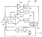
- the muscle evaluation system 100 disclosed in Patent Document 2 utilizes the inverting amplifier circuit 102 that amplifies and detects the surface muscle action potential, and detects the bioelectrodes 101+, It is possible to determine the close contact of 101-.
- the muscle evaluation system 100 will be described with reference to FIG. 1.
- a pair of bioelectrodes 101+ and 101 ⁇ that are in close contact with the muscle body surface are connected to a non-inverting input and an inverting input of an operational amplifier 102, respectively.
- a myoelectric signal hereinafter, referred to as an EMG signal
- EMG signal myoelectric signal of the difference between the surface muscle action potentials appearing between the pair of bioelectrodes 101+ and 101- is amplified by the operational amplifier 102 and output.
- the EMG signal output from the operational amplifier 102 is converted into a digital signal by an A / D converter 103 connected to the output side of the operational amplifier 102, and the activity of the muscle is controlled by a microprocessor (not shown) connected to the output side of the A / D converter 103. The condition is evaluated.
- a common electrode 104 is adhered to the vicinity of the body surface to which the pair of bioelectrodes 101+ and 101 ⁇ adhere, and a test signal is output from the test signal output circuit 110 to the common electrode 104 under the control of the clock / trigger circuit 109.
- the pair of bioelectrodes 101+ and 101 ⁇ are connected to the non-inverting input and the inverting input of the operational amplifier 102, and are connected to the amplifier circuits 105 and 106 that are separately configured from the operational amplifier 102, respectively.
- Outputs of the circuits 105 and 106 are A / D-converted by A / D converters 107 and 108 connected to outputs of the amplifier circuits 105 and 106, respectively, at a timing when the clock / trigger circuit 109 outputs a test signal.
- the A / D converters 107 and 108 perform A / D conversion at a timing when a test signal is output to the common electrode 104.
- the output test signal is output.
- the muscle evaluation system disclosed in Patent Document 1 outputs test signals alternately to one set of bioelectrodes in order to determine the closeness of one set of bioelectrodes to the body surface. It is necessary to connect the detection means for detecting the test signal separately from the detection means for detecting the surface muscle action potential appearing to the common electrode, and the signal of the test signal is compared with the surface muscle action potential appearing on a set of biological electrodes. Since the intensity is extremely high, it was not possible to simultaneously detect the surface muscle action potential and determine the close contact state of a set of biological electrodes.
- test signal is output alternately to a set of bioelectrodes to determine any bioelectrode that is not in close contact with the body surface
- output control of the test signal and detection control of the test signal are complicated.
- the amplifier circuits 105 and 106 and the A / D converters 107 and 108 are omitted, and the output of the operational amplifier 102 including the EMG signal of the surface muscle action potential includes the test signal at the output timing of the test signal.
- Another embodiment describes a muscle evaluation system that determines that the bioelectrodes 101+ and 101- are not in close contact with the body surface when they are not in contact. However, connecting the pair of bioelectrodes 101+ and 101- to the non-inverting input and the inverting input of the operational amplifier 102 appears on the pair of bioelectrodes 101+ and 101- by utilizing the common mode removal function of the operational amplifier 102.
- the inverting input and the non-inverting input of the operational amplifier 102 are intentionally unbalanced, and when one set of the bioelectrodes 101+ and 101- is normally in close contact with the body surface, the test signal is output. Appears in the output of the operational amplifier 102, and when a test signal of a predetermined signal voltage corresponding to the unbalance is not output, it is determined that the set of bioelectrodes 101+ and 101- is not in close contact with the body surface.
- the present invention has been made in view of such a conventional problem, and a differential amplifier circuit for detecting a surface muscle action potential is also used as a detection circuit for determining the close contact of a bioelectrode on a body surface. It is another object of the present invention to provide a muscle evaluation system capable of determining whether a bioelectrode is in close contact with a body surface even during detection of a surface muscle action potential.
- Another object of the present invention is to provide a muscle evaluation system capable of judging the close contact of each bioelectrode with the body surface without providing a detecting means for detecting a test signal for each set of bioelectrodes.
- the differential amplifier circuit that detects the surface muscle action potential is also used as a detection circuit that determines the adhesion of the bioelectrode to the body surface, the muscle that completely removes the common mode noise that appears on a set of bioelectrodes
- the purpose is to provide an evaluation system.
- the muscle evaluation system includes a pair of bioelectrodes exposed on a back surface of an insulating sheet facing a body surface, and a pair of bioelectrodes exposed to inverting input and non-inverting, respectively.
- a differential amplifier circuit that is connected to the input, amplifies the difference between the inverting input and the non-inverting input, and outputs the amplified signal.
- the surface appearing on the set of bioelectrodes in a state in which the set of bioelectrodes is in close contact with the body surface A muscle evaluation system that amplifies the difference between muscle action potentials and evaluates the activity of muscles in the body surface to which a set of bioelectrodes are in close contact from a myoelectric signal output from a differential amplifier circuit.
- a common electrode that is attached to and exposed to the body surface in the middle of a pair of biological electrodes, a test signal output unit that outputs a common mode test signal of a predetermined frequency to the common electrode, and a differential amplifier circuit.
- Predetermined frequency common mode If the signal strength of the common mode test signal extracted by the signal extracting means for extracting the strike signal and the common mode test signal extracted by the signal extracting means exceeds a predetermined allowable signal strength, it is determined that any of the bioelectrodes is not in close contact with the body surface. And a closeness determination unit that performs the determination.
- a differential amplifier circuit that connects an inverting input and a non-inverting input to a set of bioelectrodes Outputs a myoelectric signal obtained by amplifying the difference between the surface muscle action potentials appearing on a set of biological electrodes, and evaluates the muscle activity from the myoelectric signal.
- a common mode test signal with almost the same signal voltage and in-phase is output to the set of bioelectrodes.
- the output of the differential amplifier circuit has a very small signal strength less than a predetermined allowable signal strength. Output a common mode test signal.
- the signal extraction unit extracts a common mode test signal of a predetermined frequency from the output of the differential amplifier circuit on which the myoelectric signal is superimposed, and the adhesion determination unit determines that the signal intensity of the common mode test signal is equal to or less than the allowable signal intensity. Therefore, it is determined that one set of the biological electrodes is in close contact with the body surface.
- the contact determining means determines that any of the bioelectrodes is not in close contact with the body surface since the signal strength of the common mode test signal extracted by the signal extracting means exceeds the allowable signal strength.
- the signal strength of the common mode test signal extracted by the signal extraction means is equal to or less than the allowable signal strength
- the adhesion determination means determines the strength of the myoelectric signal output from the differential amplifier circuit.
- the signal strength of the common mode test signal extracted by the signal extraction means is equal to or less than the allowable signal strength, regardless of whether the set of bioelectrodes is in close contact with the body surface.
- the signal strength of the myoelectric signal representing the surface muscle action potential output from the differential amplifier circuit exceeds a predetermined signal strength threshold. Since the signal strength exceeds the threshold, the signal strength of the myoelectric signal is equal to or less than the predetermined signal strength threshold value, so that it can be determined that none of the bioelectrodes is in close contact with the body surface.
- the muscle evaluation system further comprising a phase comparison circuit that compares the phase of the common mode test signal extracted by the signal extraction unit with the phase of the common mode test signal output by the test signal output unit.
- a phase comparison circuit that compares the phase of the common mode test signal extracted by the signal extraction unit with the phase of the common mode test signal output by the test signal output unit.
- the common mode test signal input to the inverting input of the differential amplifier circuit is output from the differential amplifier circuit in the opposite phase to the common mode test signal output by the test signal output means, and is input to the non-inverting input.
- the signal is output from the differential amplifier circuit in the same phase as the common mode test signal output by the test signal output means. Therefore, when the phase of the common mode test signal extracted by the signal extraction means is in phase with the common mode test signal output by the test signal output means, the common mode test signal does not appear on the biological electrode connected to the inverting input, It is determined that the bioelectrode is not in close contact with the body surface.
- the phase of the common mode test signal extracted by the signal extraction unit is opposite to the common mode test signal output by the test signal output unit, the common mode test signal is displayed on the bioelectrode connected to the non-inverting input. Therefore, it is determined that the bioelectrode is not in close contact with the body surface.
- the adhesion determining means sets a common mode test output from the differential amplifier circuit using the output voltage of the differential amplifier circuit as a reference voltage when the inverting input and the non-inverting input are short-circuited.
- the signal voltage of the signal is equal to or higher than the upper limit voltage obtained by adding a predetermined allowable voltage error to the reference voltage
- the voltage is equal to or lower than the lower limit voltage obtained by subtracting the allowable voltage error from the reference voltage, it is determined that the other bioelectrode connected to the inverting input of the differential amplifier circuit is not in close contact with the body surface.
- the signal voltage of the common mode test signal output from the differential amplifier circuit is a voltage obtained by adding a reference voltage to a voltage obtained by amplifying a difference voltage between the common mode test signal input to the inverting input and the non-inverting input. In the state where the bioelectrode is in close contact with the body surface, no difference voltage is generated, so that the reference voltage is used.
- the adhesion determination unit determines It is determined that the other biological electrode connected to the inverting input is not in close contact with the body surface.
- the muscle evaluation system according to claim 5 is characterized in that the common electrode is exposed so as to protrude from the back surface of the insulating sheet from a set of living body electrodes.
- the common electrode that protrudes from the bioelectrode to the body surface also adheres to the body surface, and outputs a common mode test signal to the common electrode to adhere to the body surface.
- a common mode test signal appears on the living body electrode.
- the muscle evaluation system wherein the distance from the common electrode exposed on the back surface of the insulating sheet to each set of living electrodes is different, and the common electrode and one set of each living body are caused by the flow of the common mode test signal.
- the potential difference between the electrodes is set as an offset voltage of the differential amplifier circuit.
- the distance between the common electrode and each set of bioelectrodes is adjusted to generate a potential difference in the signal voltage of the common mode test signal appearing on the set of bioelectrodes, which is used as the offset voltage of the differential amplifier circuit.
- the differential amplifier circuit can amplify and output the difference between the inverting input and the non-inverting input with high precision without preparing a voltage power supply.
- the signal extracting means extracts a common mode test signal having a predetermined frequency from an output of the differential amplifier circuit including the myoelectric signal.
- a signal of a predetermined frequency is separated from the output of the differential amplifier circuit to extract a common mode test signal, and a set of It is determined whether or not the living body electrode is in close contact with the body surface.
- the first aspect of the present invention it is determined whether or not a set of bioelectrodes is in close contact with the body surface by using the common mode removal function of the differential amplifier circuit that detects surface muscle action potentials. There is no need to provide another detecting means for detecting the mode test signal.
- test signal output means outputs a common mode test signal of a predetermined frequency to the common electrode
- the myoelectric signal and the common mode test signal are superimposed on the output of the differential amplifier circuit, and the myoelectric signal is detected to detect the myoelectric signal. Even during the evaluation of the activity, it is possible to extract only the common mode test signal and determine the adhesion of the bioelectrode to the body surface from the signal strength of the extracted common mode test signal.
- the common mode noise that appears on the set of bioelectrodes while the set of bioelectrodes is in close contact with the body surface is removed from the output by the common mode rejection function of the differential amplifier circuit. From the unaffected myoelectric signals, it is possible to evaluate activities such as muscle fatigue status and increase / decrease in the number of mobilizations.
- a common mode test signal having a predetermined signal strength is output from the differential amplifier circuit. Any biological electrode that is not in close contact with the body surface can be determined from the phase.
- the second aspect of the present invention it is possible to determine a case where none of a set of biological electrodes is in close contact with the body surface.
- the phase of the common mode test signal extracted by the signal extraction unit and the phase of the common mode test signal output by the test signal output unit are compared, and any one of the set of bioelectrodes is brought into close contact with the body surface. You can determine whether or not.
- the fourth aspect of the invention it is possible to determine any of the bioelectrodes that are not in close contact with the body surface from the signal voltage of the common mode test signal output from the differential amplifier circuit without using the phase comparison circuit.
- the common mode test signal since the common mode test signal can be reliably transmitted to the living body electrode in close contact with the body surface, the common mode test signal does not flow from the common electrode to the body surface. Adhesion of a set of bioelectrodes to the body surface can be reliably determined without erroneous determination of the adhesion of the bioelectrode to the body surface.
- the inverting input and the differential amplifier circuit can be used.
- the difference between non-inverting inputs can be amplified and output with high precision.
- the close contact state of the bioelectrode on the body surface can be determined at the same time.
- the state in which the bioelectrode is separated from the body surface can be immediately detected.
- FIG. 9 is a cross-sectional view showing a state in which an insulating sheet 30 is adhered to a back surface 30 a of a body surface 51 of a streak 50. It is a block diagram of muscle evaluation system 20 concerning a 2nd embodiment.
- FIG. 2 is a block diagram of a differential amplifier circuit 21.
- FIG. 9 is a waveform diagram showing an output of the FFT analyzer 22 during a time when a pair of bioelectrodes 2+ and 2- closely adhere to the body surface 51 and the muscle 50 is arbitrarily contracted.
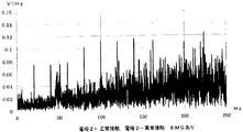
- FIG. 9 is a waveform diagram showing an output of the FFT analyzer 22 during a time when a pair of bioelectrodes 2+ and 2- closely adhere to the body surface 51 and the muscle 50 is arbitrarily contracted.
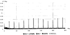
- FIG. 9 is a waveform diagram showing an output of the FFT analyzer 22 during a time when a pair of bioelectrodes 2+ and 2- closely adhere to the body surface 51 and the muscle 50 is not voluntarily contracted.
- FIG. 9 is a waveform diagram showing an output of the FFT analyzer 22 while the muscle 50 is arbitrarily contracted in a state where one of a pair of bioelectrodes 2+ and 2- is not in close contact with the body surface 51.
- FIG. 9 is a waveform diagram showing an output of the FFT analyzer 22 while the muscle 50 is not arbitrarily contracted in a state where one of a pair of bioelectrodes 2+ and 2- is not in close contact with the body surface 51.
- It is a block diagram showing the conventional muscle evaluation system 100.
- the muscle evaluation system 1 includes a set of bioelectrodes 2+ and 2- that make a muscle action potential propagated along a muscle fiber of the muscle 50 when the muscle 50 voluntarily contracts close to a body surface 51 of the muscle 50.
- the abnormalities and fatigue of the muscle 50 are evaluated from the detected and amplified myoelectric signals (hereinafter referred to as EMG signals) in which the muscle action potentials are continuous, and a set of bioelectrodes 2+ and 2- is attached to the body surface 51.
- EMG signals detected and amplified myoelectric signals
- a close determination is made as to whether or not there is close contact.
- the bioelectrode 2 is in close contact with the body surface 51 means that the bioelectrode 2 and the body surface 51 are low enough that a muscle action potential sufficient to evaluate the state of the muscle 50 appears on the bioelectrode 2.
- the state of contact with contact resistance is referred to as normal contact.
- the state of close contact is referred to as normal contact, and the state where muscle action potential sufficient to evaluate the state of muscle 50 does not appear on bioelectrode 2 is referred to as abnormal contact. That.
- a pair of bioelectrodes 2+ and 2- are attached to both sides of the elongated insulating sheet 30 in the longitudinal direction so as to be in close contact with the body surface 51 along the muscle fibers of the muscle 50.
- the electrode surface is exposed on the back surface 30a on the side opposite to.
- a pair of bioelectrodes 2+ and 2- are connected to a non-inverting input 5+ and an inverting input 5- of an operational amplifier 5 constituting a differential amplifier circuit, respectively.
- the difference between the action potential and the potential of a common mode test signal described later is amplified and output. Therefore, the operational amplifier 5 has a common mode elimination function of removing, from its output, signals input to the non-inverting input 5+ and the inverting input 5- at the same phase and at the same level.
- a common electrode 4 to which a common mode test signal is output from the test signal output circuit 3 is mounted in the middle of the one set of the bioelectrodes 2+ and 2 ⁇ mounted on the insulating sheet 30.
- the electrode surface of the common electrode 4 is also exposed on the back surface 30 a of the insulating sheet 30, and the exposed position is adjusted according to the offset voltage Vos of the operational amplifier 5. That is, the distance between the common electrode 4 and the living body electrode 2+, which is in close contact with the body surface 51, and the distance between the common electrode 4 and the living body electrode 2 are made slightly different, so that the impedance between the common mode test signal flows is made different.
- the exposed position of the common electrode 4 is set so that the potential difference of the common mode test signal appearing at each of the bioelectrodes 2+, 2- coincides with the potential difference corresponding to the offset voltage Vos of the operational amplifier 5. To either side. As a result, the difference between the muscle action potential and the common mode test signal input to the non-inverting input 5+ and the inverting input 5- of the operational amplifier 5 is amplified and output without being affected by the internal error of the operational amplifier 5. .
- the common electrode 4 is thicker than the pair of bioelectrodes 2+, 2-, and further projects downward from the position where the pair of bioelectrodes 2+, 2-exposes on the back surface 30a of the insulating sheet 30 as shown in FIG. Then, it is brought into contact with the body surface 51 pushed inward.
- the signal strength of the common mode test signal appearing on the pair of bioelectrodes 2+ and 2- The state of contact with the body surface 51 can be determined.
- the test signal output circuit 3 outputs a common mode test signal of a voltage and a current that does not give a stimulus to a subject.
- a current of about 150 nA flows.
- the common mode test signal is output to the common electrode 4.
- the frequency of the common mode test signal is set to a predetermined frequency so that it can be detected from a signal appearing on the pair of bioelectrodes 2+ and 2-. In this case, the muscle generated when the muscle 50 contracts voluntarily.
- the EMG signal detected from the action potential is approximately 1 kHz or less, and the common mode test signal is also passed through the biological signal filter 6 that passes the EMG signal.
- the frequency is set to 20 Hz so that it can be identified and extracted.
- the biological signal filter 6 connected to the output of the operational amplifier 5 allows the output signal including the EMG signal having a frequency of 1 kHz or less and the output signal including the common mode test signal to pass from the output signal of the operational amplifier 5, and the logger 8 and the contact determination circuit. It outputs to the 9 and 20 Hz bandpass filters 7.
- the EMG signal output from the biological signal filter 6 is a signal output from the operational amplifier 5 having a common mode elimination function.
- the muscle action potential propagates along the muscle fiber of the muscle 50, and a set of biological signals is generated.
- the muscle action potentials having different phases appear on the electrodes 2+ and 2-, and are input to the non-inverting input 5+ and the inverting input 5- of the operational amplifier 5, so that the operational amplifier 5 amplifies the difference between the muscle action potentials having different phases.
- An EMG signal is output.
- the logger 8 records the EMG signal obtained by amplifying the difference between the muscle action potentials output from the biological signal filter 6 together with the elapsed time, and outputs the EMG signal to the microcomputer 10.
- the frequency, amplitude and changes in the EMG signal depend on the contractile activity of the muscle 50. For example, when the fatigue of the voluntarily contracting muscle 50 is increased, the number of mobilized motor units and the firing frequency for supplementing the contractility of the muscle 50 are reduced.
- the microcomputer 10 evaluates various activities of the muscle 50 from changes in the EMG signal input from the logger 8 and the elapsed time.
- a display device 11 and a speaker 12 are connected to the microcomputer 10, and the evaluation result of the streak 50 evaluated by the microcomputer 10 is displayed on the display device 11 and / or a sound emitted from the speaker 12 to use the streak evaluation system 1.
- the microcomputer 10 evaluates, the speaker 12 emits a voice prompting to stop the contraction movement of the muscle 50.
- the bandpass filter 7 further allows a signal of 20 Hz to pass from the output of the biological signal filter 6 to extract a common mode test signal, and outputs it to the phase comparison circuit 13 and the contact determination circuit 9.
- the phase circuit 9 compares the common mode test signal output from the bandpass filter 7 with the output timing of the common mode test signal from the test signal output circuit 3 and has the same phase as the common mode test signal output from the test signal output circuit 3. And whether the phases are reversed.
- the bioelectrode 2 connected to the inverting input 5 of the operational amplifier 5 is not in close contact with the body surface 51 of the set of bioelectrodes 2+ and 2-, the common mode test signal appearing on the bioelectrode 2+ Exceeds the inverting input 5 and is input to the non-inverting input 5+, so that the common mode test signal included in the output of the operational amplifier 5 is in phase with the common mode test signal output from the test signal output circuit 3, and the phase comparison is performed.
- the circuit 13 outputs the in-phase comparison result to the contact determination circuit 9.
- the phase comparison circuit 13 outputs a comparison result having an opposite phase to the contact determination circuit 9.
- the contact determination circuit 9 determines a set of each bioelectrode from the EMG signal output from the biological signal filter 6, the common mode test signal output from the bandpass filter 7, and the comparison result output from the phase comparison circuit 13. The contact state of the contact determination circuit 9 is determined in detail below.
- the contact determination circuit 9 determines that the signal strength of the common mode test signal output from the bandpass filter 7 is equal to or less than a predetermined allowable signal strength. Since the EMG signal output from the biological signal filter 6 exceeds a predetermined signal strength threshold value, it is determined that both of the pair of biological electrodes 2+ and 2- are in normal contact.
- the muscle action potential does not appear in the set of bioelectrodes 2+ and 2-, and is not input to the non-inverting input 5+ and the inverting input 5- of the operational amplifier 5, so that the EMG signal output from the biosignal filter 6 is If the signal strength of the common mode test signal output from the bandpass filter 7 is equal to or less than a predetermined allowable signal strength and the EMG signal output from the biological signal filter 6 is also a predetermined signal, Since the intensity is equal to or less than the intensity threshold value, it is determined that any of the pair of biological electrodes 2+ and 2- is abnormal contact.
- the contact determination circuit 9 It is determined that the bioelectrode 2+ connected to the non-inverting input 5+ is in normal contact and the bioelectrode 2- connected to the inverting input 5 is in non-contact.
- the signal strength of the common mode test signal output from the bandpass filter 7 exceeds a predetermined allowable signal strength and the comparison result of the opposite phase is input from the phase comparison circuit 13
- the bioelectrode 2- connected to the inverting input of the operational amplifier 5 is in normal contact, and the bioelectrode 2+ connected to the non-inverting input 5+ is non-contact.
- the common mode test signal output from the operational amplifier 5 Is set to a reference voltage, for example, 1 / the signal voltage of the common mode test signal input to the operational amplifier 5 when the output voltage of the operational amplifier 5 when the inverting input 5 ⁇ and the non-inverting input 5+ are short-circuited is used as the reference voltage.
- the bioelectrode 2+ connected to the non-inverting input 5+ of the operational amplifier 5 makes abnormal contact
- the bioelectrode 2- connected to the inverting input 5 makes normal contact.
- the voltage is equal to or lower than the lower limit voltage obtained by subtracting the allowable voltage error from the reference voltage. Therefore, when the signal strength of the common mode test signal output from the bandpass filter 7 exceeds a predetermined allowable signal strength and one of the pair of bioelectrodes 2+ and 2- is in normal contact, the contact determination circuit 9 is also used to compare whether the signal voltage of the common mode test signal output from the bandpass filter 7 is equal to or higher than the upper limit voltage or equal to or lower than the lower limit voltage without using the comparison result of the phase comparison circuit 13. Which of the biological electrodes 2+ and 2- is abnormal contact can be determined.
- the contact determination circuit 9 determines that one or both of the pair of bioelectrodes 2+ and 2- is abnormal contact
- the contact determination circuit 9 outputs the determination result to the microcomputer 10, and the microcomputer 10 displays the determination result indicating the abnormal contact.
- the information is transmitted to the user by a display on the device 11 and / or a sound emitted from the speaker 12. Therefore, the set of bioelectrodes 2+, 2- is brought into close contact with the body surface 51 of the muscle 50, and the abnormalities of the bioelectrodes 2+, 2- are evaluated before the muscle 50 is evaluated from the EMG signal or during the exercise of voluntarily contracting the muscle 50. Contact can be transmitted to the user, and re-adhesion of the bioelectrodes 2+ and 2- can be promoted.
- a muscle evaluation system 20 according to the second embodiment of the present invention will be described with reference to FIGS.
- the components of the muscle evaluation system 20 that have the same or similar functions as those of the muscle evaluation system 1 described above, the detailed description thereof will be omitted using the same reference numerals.
- This muscle evaluation system 20 also provides a muscle action potential transmitted along the muscle fibers of the muscle 50 when the muscle 50 voluntarily contracts from a set of bioelectrodes 2+ and 2- Unlike the muscle evaluation system 1, the pair of bioelectrodes 2 + and 2-and the common electrode 4 whose electrode surfaces are exposed on the back surface 30 a of the insulating sheet 30 are connected to the non-inverting input 21 + and the inverting input 21-, respectively. , A differential amplifier circuit 21 connected to the ref input 21R, an AD converter 23 for A / D converting an analog output of the differential amplifier circuit 21, and an EMG signal of the differential amplifier circuit 21 A / D converted by the AD converter 23. And an FFT analyzer 22 that performs a fast Fourier transform on an output signal including the common mode test signal and calculates a signal strength for each frequency.
- the differential amplifier circuit 21 includes a first non-inverting amplifier circuit 21A and a second non-inverting amplifier circuit 21B in which an output of the first non-inverting amplifier circuit 21A is connected to an inverting input via a second input resistor Rs2. As shown in FIG. 4, the non-inverting input 21+ and the inverting input 21- of the differential amplifier circuit 21 are connected to the non-inverting inputs of the second operational amplifier U2 and the first operational amplifier U1, respectively. potential appearing 2 to Vin + and Vin - a second operational amplifier U2 respectively are input to the non-inverting input of the first operational amplifier U1.
- the ref input 21R of the differential amplifier circuit 21 connected to the common electrode 4 is connected to the inverting input of the first operational amplifier U1 via the inverting input resistor Rs1, and the signal of the common mode test signal output to the common electrode 4 is output.
- the voltage Vt is input to the inverting input of the first operational amplifier U1.
- the ratio of the resistance value of the first feedback resistor Rf1 to the first input resistor Rs1 of the first non-inverting amplifier circuit 21A is k
- the ratio of the resistance value of the second non-inverting amplifier circuit 21B to the second input resistor Rs2 is k.
- the ratio of the resistance value of the second feedback resistor Rf2 is 1 / k, which is the reciprocal of the above ratio.
- the differential amplifier circuit 21 removes a common mode rejection signal in which Vin + and Vin ⁇ input to the non-inverting input 21+ and the inverting input 21 ⁇ in the same phase have the same level.
- the signal voltage Vt of the common mode test signal to be input to the ref input 21R, a pair of bioelectrode 2 +, the potential Vin + appearing in 2-Vin - was amplified in the difference in (1 + k) / k
- the output signal to which the voltage is applied is output to the biological signal filter 6.
- the voltage gain A of the differential amplifier circuit 21 represented by (1 + k) / k is set to 1000, and the difference between the signal voltages of the common mode test signals appearing in the pair of bioelectrodes 2+ and 2- is obtained. , 0.2 mV, the differential amplifier 21 outputs a common mode test signal having a signal voltage of 200 mV.
- the biological signal filter 6 connected to the output of the differential amplifier circuit 21 passes an output signal including an EMG signal having a frequency of 1 kHz or less and a common mode test signal from the output signal of the differential amplifier circuit 21 and connects to the output side.
- a / D conversion is performed by the A / D converter 23, and the digital signal is calculated by the FFT analyzer 22.
- the output signal which is a digital signal output from the AD converter 23 includes an EMG signal and a common mode test signal
- the common mode test signal includes a ref input 21R as shown in Expression (3).
- Both the input common mode test signal and the common mode test signal obtained by amplifying the difference between the signal voltages of the common mode test signals appearing on each set of the biological electrodes 2+ and 2- by 1000 times are included.
- the difference between the common mode test signals appearing on the set of bioelectrodes 2+ and 2- is 0 or a small value, and the difference between the pair of bioelectrodes 2+ and 2- Any common mode test signal is negligible compared to the EMG signal output from the AD converter 23 by amplifying the difference of the appearing EMG signal by 1000 times. Sai.
- the output signal A / D-converted by the AD converter 23 can be regarded as representing the EMG signal as it is, and is temporarily stored in the logger 8.
- the microcomputer 10 evaluates the activity of the muscle 50 from the EMG signal stored in the logger 8 and transmits the result to the user via the display device 11 or the speaker 12.
- the microcomputer 10 receives a determination result from the contact determination circuit 9 that at least one of the pair of bioelectrodes 2+ and 2- is in abnormal contact as described later, the AD stored in the logger 8 is detected. Since the output signal of converter 23 includes a common mode test signal that cannot be ignored, it is not regarded as an EMG signal, and the activity of muscle 50 is not evaluated from the output signal.
- the output signal of the AD converter 23 is also output to the FFT analyzer 22 and the phase comparison circuit 13, and the FFT analyzer 22 performs a fast Fourier transform on the output signal of the AD converter 23 in a band including the EMG signal and the common mode test signal,
- the signal strength for each frequency is calculated, and the signal strength calculated for the common mode test signal of 20 Hz is output to the contact determination circuit 9.
- the FFT analyzer 22 expresses the signal strength for each frequency of the output signal of the AD converter 23 with the power value calculated by the square of the signal voltage per unit frequency width (1 Hz width), and the FFT analyzer 22 calculates for 20 Hz.
- the power value is used as the signal strength of the common mode test signal
- the signal power or signal voltage of the common mode test signal of 20 Hz output from the AD converter 23 may be used as the signal strength of the common mode test signal.
- the FFT analyzer 22 since the FFT analyzer 22 also calculates the signal strength of each frequency of the EMG signal, the FFT analyzer 22 outputs the calculation result to the logger 8 or the microcomputer 10, and the microcomputer 10 calculates the signal strength from the signal strength of each frequency of the EMG signal. , The activity of muscle 50 can also be evaluated.
- the common mode test signal output from the AD converter 23 includes the common mode test signal input to the ref input 21R of the differential amplifier circuit 21 as shown in Expression (3). Even if the respective biological electrodes 2+ and 2- are in normal contact, the signal strength of the 20 Hz common mode test signal output from the FFT analyzer 22 does not become zero. Further, even if the bioelectrodes 2+ and 2- are not completely in contact with the body surface 51, a signal intensity capable of evaluating the activity of the muscle 50 is detected from the signal level of the common mode test signal appearing on the bioelectrodes 2+ and 2-.
- the contact determination circuit 9 sets a predetermined allowable signal strength, and sets any one of them only when the signal strength of the common mode test signal of 20 Hz output from the FFT analyzer 22 exceeds this allowable signal strength. Are determined to be abnormal contacts.
- the contact determination circuit 9 determines that one of the set of bioelectrodes 2+ and 2- The other is determined to be abnormal contact, and it is determined which one is abnormal by referring to the phase determination result of the phase comparison circuit 13.
- FIG. 6 shows a state where a common mode test signal of 20 Hz and 0.3 mV is output from the test signal output circuit 3 and the pair of bioelectrodes 2+ and 2- are in normal contact without arbitrarily contracting the muscle 50.
- FIG. 4 is an output diagram output from the FFT analyzer 22 of FIG. 5.
- the signal strength of the 20 Hz common mode test signal calculated by the FFT analyzer 22 by the common mode removal function of the differential amplifier circuit 21 is 0.0017 V 2 / Hz. Has become.
- FIG. 8 showing an output diagram output from the FFT analyzer 22 under the same condition and one set of one of the biological electrodes 2 is in abnormal contact, a signal of 20 Hz and its multiple appear remarkably.
- FIG. 5 shows the output diagram of FIG. 6 showing the output of the FFT analyzer 22 in a state where the pair of bioelectrodes 2+ and 2- normally contact each other under the same conditions as in FIG.
- the muscle 50 voluntarily contracts, one of the pair of bioelectrodes 2+ and 2 ⁇ is erroneously determined to be an abnormal contact.
- the voltage becomes 0.0489 V 2 / Hz or more, and when any one of the pair of bioelectrodes 2+, 2- comes into normal contact, the voltage becomes 0.0169 V 2 / Hz or less. If the allowable signal strength is set during this time, even if the muscle 50 is arbitrarily contracted, it is possible to determine abnormal contact of one of the pair of bioelectrodes 2+ and 2-.
- the phase comparison circuit 13 compares the phase of the common mode test signal output from the AD converter 23 with the phase of the common mode test signal output from the test signal output circuit 3.
- the common mode test signal included in the output from the AD converter 23 includes a common mode test signal input to the ref input 21R of the differential amplifier circuit 21 and a common mode test signal appearing on each set of the biological electrodes 2+ and 2-. And the common mode test signal amplified by the differential amplifier circuit 21.
- the contact determination circuit 9 refers to one of the biological electrodes 2+, 2 When-is non-contact, the former common mode test signal is negligibly small compared to the latter common mode test signal.
- the phase comparison circuit 13 converts the amplified common mode test signal output from the AD converter 23 representing the difference between the signal voltages of the common mode test signals appearing on the set of each of the biological electrodes 2+, 2 ⁇ into a test signal output circuit. 3 is compared with the phase of the common mode test signal.
- a common mode test output from the AD converter 23 The signal is in phase with the common mode test signal output from the test signal output circuit 3, the phase comparison circuit 13 outputs the in-phase comparison result to the contact determination circuit 9, and the contact determination circuit 9 outputs the result from the FFT analyzer 22. Since the signal strength of the common mode test signal exceeds the allowable signal strength and the in-phase comparison result is input from the phase comparison circuit 13, it is determined that the bioelectrode 2+ is normal and the bioelectrode 2 is abnormal. .
- the common output from the AD converter 23 is The mode test signal has a phase opposite to that of the common mode test signal output from the test signal output circuit 3.
- the phase comparison circuit 13 outputs the comparison result of the opposite phase to the contact determination circuit 9, and the contact determination circuit 9 Since the signal strength of the common mode test signal output from the analyzer 22 exceeds the permissible signal strength and the result of the opposite phase comparison is input from the phase comparison circuit 13, the bioelectrode 2+ abnormally contacts and the bioelectrode 2- Judge as normal contact.
- the contact determination circuit 9 determines whether any one of the pair of bioelectrodes 2+ and 2- is in normal contact or none. Judge as abnormal contact.
- the contact determination circuit 9 determines whether any one of the pair of bioelectrodes 2+ and 2- is in normal contact or none. Judge as abnormal contact.
- both of the set of bioelectrodes 2+ and 2- are in normal contact, surface muscle action potentials having different phases appear on the set of bioelectrodes 2+ and 2-, and the differential amplifying circuit 21 Then, an EMG signal having a predetermined signal intensity obtained by amplifying the difference is output from the AD converter 23 to the FFT analyzer 22.
- the contact determination circuit 9 determines the signal strength of the EMG signal output from the FFT analyzer 22 for each frequency, Integrates in a band where the EMG signal exists (for example, 0 to 250 Hz), and furthermore, when the signal strength of the EMG signal represented by the integrated value is equal to or higher than a predetermined value, one of the pair of bioelectrodes 2+ and 2- Is normal contact, and if less than the predetermined value, both of the set of bioelectrodes 2+ and 2- are determined to be abnormal contact.
- the determination result by the contact determination circuit 9 is output to the microcomputer 10 as in the first embodiment, and the microcomputer 10 conveys the determination result to the user by displaying the result on the display device 11 and / or sound emitted from the speaker 12. . Therefore, when any of the bioelectrodes 2+, 2- does not adhere to the body surface 51 of the muscle 50, the user can know about the abnormally-contacted bioelectrodes 2+, 2-, and makes a normal contact. Can be re-attached.
- each set of three or more bioelectrodes to be brought into close contact with the body surface 51 is connected to a differential amplifier circuit having a common mode removal function, and a common mode test signal included in the output of each differential amplifier circuit. It can be determined from all the three or more biological electrodes whether the contact is normal or abnormal.
- the contact determination circuit determines whether the pair of bioelectrodes 2+ and 2- is in abnormal contact and whether one of the bioelectrodes 2+ and 2- is in abnormal contact. Alternatively, it may be possible to determine whether only one set of the biological electrodes 2+, 2- is in normal contact or only one of them is in abnormal contact.
- the present invention has been described with an example of a muscle evaluation system that evaluates a muscle activity state from a muscle action potential when a muscle voluntarily contracts.
- a muscle evaluation system that detects the activity state of the muscle by detecting from a biological electrode that is in close contact with the surface may be used.
- the present invention is suitable for an evaluation system for evaluating the activity state of a muscle by bringing a set of bioelectrodes into close contact with the surface of a muscle body.
Landscapes
- Life Sciences & Earth Sciences (AREA)
- Health & Medical Sciences (AREA)
- Medical Informatics (AREA)
- Biophysics (AREA)
- Pathology (AREA)
- Engineering & Computer Science (AREA)
- Biomedical Technology (AREA)
- Heart & Thoracic Surgery (AREA)
- Physics & Mathematics (AREA)
- Molecular Biology (AREA)
- Surgery (AREA)
- Animal Behavior & Ethology (AREA)
- General Health & Medical Sciences (AREA)
- Public Health (AREA)
- Veterinary Medicine (AREA)
- Measurement And Recording Of Electrical Phenomena And Electrical Characteristics Of The Living Body (AREA)
Abstract
【課題】表面筋活動電位を検出する差動増幅回路を、生体電極の体表面への密着を判定する検出回路に兼用し、表面筋活動電位を検出する間であっても、生体電極の体表面への密着を判定できる筋評価システムを提供する。 【解決手段】一組の生体電極を反転入力と非反転入力に接続し、一組の生体電極に表れる表面筋活動電位の差分を出力する差動増幅回路のコモンモード除去機能を利用し、一組の生体電極の中間で体表面に密着するコモン電極にコモンモードテスト信号を出力し、差動増幅回路から所定の信号強度のコモンモードテスト信号が出力されることから、いずれかの生体電極が体表面に密着していないと判定する。
Description
本発明は、筋の体表面に密着させた生体電極に表れる表面筋活動電位から筋の活動状態を評価する筋評価システムに関し、更に詳しくは、表面筋活動電位が表れる生体電極と体表面との密着状態を併せて判定する筋評価システムに関する。
骨格筋は、脳からの神経刺激によって随意収縮する際に活動電位を生じるので、従来から筋の体表面に密着させた一組の生体電極間に表れる表面筋活動電位を検出して、表面筋活動電位の波形である筋電図(electromyogram:EMG)から筋の異常や疲労の状態を評価する筋評価システムが知られている。この表面筋活動電位は、数μVからmVと極めて微小な電圧であるので、いずれかの生体電極と体表面の間に汗や塵埃等の異物が介在し、生体電極と体表面間が低インピーダンスで密着していないと、検出精度が著しく低下し、正確に筋の活動状態を評価することができなかった。
そこで、一組の生体電極が密着する体表面の近傍にコモン電極を密着させて、生体電極とコモン電極のいずれか一方からテスト信号を出力し、他方に所定レベルのテスト信号が表れない場合に、生体電極が体表面に密着していないと判定し、その判定結果を測定者へ伝える筋評価システムが知られている。このうち、特許文献1に開示された筋評価システムでは、体表面に密着する一組の生体電極から交互にテスト信号を出力し、一組の生体電極が密着する体表面の中間に密着させたコモン電極に所定レベルのテスト信号が表れるか否かを判定し、いずれかの生体電極にテスト信号の出力してもコモン電極から所定レベルのテスト信号を検出できなかった場合に、その生体電極が体表面に密着していないと判定している。
また、特許文献2に開示された筋評価システム100は、表面筋活動電位を増幅して検出する反転増幅回路102を利用して、表面筋活動電位の検出中であっても、生体電極101+、101-の密着を判定可能としている。以下、この筋評価システム100を、図従1を用いて説明すると、筋の体表面に密着させる一組の生体電極101+、101-はオペアンプ102の非反転入力と反転入力に接続して、一組の生体電極101+、101-間に表れる表面筋活動電位の差分の筋電信号(以下、EMG信号という)がオペアンプ102で増幅されて出力される。オペアンプ102から出力されたEMG信号は、オペアンプ102の出力側に接続されたA/Dコンバータ103でデジタル信号に変換され、A/Dコンバータ103の出力側に接続する図示しないマイクロプロセッサで筋の活動状態が評価される。
一組の生体電極101+、101-が密着する体表面の近傍には、コモン電極104が密着され、このコモン電極104にクロック/トリガー回路109の制御でテスト信号出力回路110からテスト信号が出力される。また、一組の生体電極101+、101-は、上述のように、オペアンプ102の非反転入力と反転入力に接続するとともに、それぞれオペアンプ102と別に構成された増幅回路105、106に接続し、増幅回路105、106の出力は、クロック/トリガー回路109がテスト信号を出力するタイミングで、増幅回路105、106の出力にそれぞれ接続するA/Dコンバータ107、108でA/D変換される。
これにより、一組の生体電極101+、101-が体表面に密着している場合には、コモン電極104にテスト信号が出力されるタイミングで、A/Dコンバータ107、108からA/D変換されたテスト信号が出力される。一方、一組の生体電極101+、101-のいずれか一方若しくは双方が体表面に密着していない場合には、体表面に密着していない生体電極101+、101-にテスト信号が流れず、その生体電極101+、101-に増幅回路105、106を介して接続するA/Dコンバータ107、108にもA/D変換されたテスト信号が出力されないことから、その体表面に密着していない生体電極101+、101-を検出できる。従って、筋評価システム100によれば、上記オペアンプ102とA/Dコンバータ103で表面筋活動電位を検出している間であっても、生体電極101+、101-の密着状態を検出できる。
特許文献1に開示された筋評価システムは、一組の生体電極の体表面への密着を判定するために、一組の生体電極に交互にテスト信号を出力するので、一組の生体電極に表れる表面筋活動電位を検出する検出手段と別にテスト信号を検出する検出手段をコモン電極に接続する必要があり、また、一組の生体電極に表れる表面筋活動電位に比較してテスト信号の信号強度は極めて大きいので、表面筋活動電位の検出と、一組の生体電極の密着状態の判定を同時に行うことができなかった。
更に、体表面に密着していないいずれかの生体電極を判定するために、一組の生体電極に交互にテスト信号を出力するので、テスト信号の出力制御と、テスト信号の検出制御が複雑になるとともに、一組の生体電極の密着状態の判定に時間を要していた。
特許文献2に開示された筋評価システム100によれば、一組の生体電極101+、101-に表れる表面筋活動電位を検出している間であっても、生体電極101+、101-の密着状態を検出できるが、特許文献1の筋評価システムと同様に、一組の生体電極101+、101-に表れる表面筋活動電位を検出するオペアンプ102及びA/Dコンバータ103の検出手段の他に一組の生体電極101+、101-にそれぞれ表れるテスト信号を検出するための増幅回路105、106及びA/Dコンバータ107、108の検出手段を別に設ける必要があり、システム全体の構造が複雑、大型化するものとなっていた。
そこで、特許文献2には、増幅回路105、106及びA/Dコンバータ107、108を省略し、表面筋活動電位のEMG信号が含まれるオペアンプ102の出力にテスト信号の出力タイミングでテスト信号が含まれていない場合に、生体電極101+、101-が体表面に密着していないと判定する筋評価システムが他の実施の形態が記載されている。しかしながら、一組の生体電極101+、101-をオペアンプ102の非反転入力と反転入力に接続するのは、オペアンプ102のコモンモード除去機能を利用して、一組の生体電極101+、101-に表れる表面筋活動電位に同相で重畳するコモンモードノイズを除去するためであり、一組の生体電極101+、101-が正常に体表面に密着している場合には、コモン電極104から一組の生体電極101+、101-に流れるテスト信号もオペアンプ102のコモンモード除去機能によりオペアンプ102の出力に表れず、体表面に密着していないと誤判定する恐れが生じる。
そのため、この実施の形態では、オペアンプ102の反転入力と非反転入力を意図的に不平衡とし、一組の生体電極101+、101-が正常に体表面に密着している場合には、テスト信号がオペアンプ102の出力に表れるようにして、不平衡に応じた所定の信号電圧のテスト信号が出力されない場合に、一組の生体電極101+、101-が体表面に密着していないと判定するが、いずれの生体電極101+、101-が密着していないかまでは判定できず、また、反転入力と非反転入力が不平衡となるので、生体電極101+、101-に表れるコモンモードノイズを除去できないという新たな課題も生じる。
更に特許文献2に開示されたこの実施態様では、オペアンプ102の出力にテスト信号が表れないことから、一組の生体電極101+、101-が体表面に密着していないことを判定するので、その出力の位相や信号電圧から一組の生体電極101+、101-のいずれが体表面に密着していないかまでは判定することができなかった。
本発明は、このような従来の問題点を考慮してなされたものであり、表面筋活動電位を検出する差動増幅回路を、生体電極の体表面への密着を判定する検出回路に兼用し、表面筋活動電位を検出する間であっても、生体電極の体表面への密着を判定できる筋評価システムを提供することを目的とする。
また、一組の生体電極毎にテスト信号を検出する検出手段を設けることなく、生体電極毎の体表面への密着を判定できる筋評価システムを提供することを目的とする。
また、一組のいずれの生体電極が体表面に密着していないかを判定可能な筋評価システムを提供する。
また、表面筋活動電位を検出する差動増幅回路を、生体電極の体表面への密着を判定する検出回路に兼用しても、一組の生体電極に表れるコモンモードノイズを完全に除去する筋評価システムを提供することを目的とする。
上述の目的を達成するため、請求項1に記載の筋評価システムは、体表面に対向する絶縁シートの裏面に露出する一組の生体電極と、一組の生体電極をそれぞれ反転入力と非反転入力に接続し、反転入力と非反転入力の差分を増幅して出力する差動増幅回路とを備え、一組の生体電極を体表面に密着させた状態で、一組の生体電極に表れる表面筋活動電位の差分を増幅して差動増幅回路から出力される筋電信号から一組の生体電極が密着する体表面内の筋の活動を評価する筋評価システムであって、絶縁シートの裏面に露出して取り付けられ、一組の生体電極の中間で体表面に密着するコモン電極と、コモン電極へ所定周波数のコモンモードテスト信号を出力するテスト信号出力手段と、差動増幅回路の出力から所定周波数のコモンモードテスト信号を抽出する信号抽出手段と、信号抽出手段で抽出したコモンモードテスト信号の信号強度が、所定の許容信号強度を越える場合に、いずれかの生体電極が体表面に密着していないと判定する密着判定手段とを、更に備えることを特徴とする。
筋活動電位は、筋繊維に沿って伝搬するので、一組の生体電極に表れる表面筋活動電位の位相は異なり、反転入力と非反転入力を一組の生体電極に接続させた差動増幅回路からは、一組の生体電極に表れる表面筋活動電位の差分を増幅した筋電信号が出力され、筋電信号から筋の活動を評価する。
一組の生体電極が体表面に密着する状態で、その中間で密着するコモン電極にコモンモードテスト信号を出力すると、一組の生体電極に、同相でほぼ同一の信号電圧のコモンモードテスト信号が表れ、反転入力と非反転入力を一組の生体電極に接続させた差動増幅回路のコモンモード除去機能により、差動増幅回路の出力には、信号強度が所定の許容信号強度以下となる微少なコモンモードテスト信号が出力される。従って、信号抽出手段は、筋電信号が重畳する差動増幅回路の出力から所定周波数のコモンモードテスト信号を抽出し、密着判定手段は、コモンモードテスト信号の信号強度が許容信号強度以下であることから、一組の生体電極が体表面に密着していると判定する。
一方、いずれかの生体電極が体表面に密着していない状態で、その中間で密着するコモン電極にコモンモードテスト信号を出力すると、一方の生体電極にのみコモンモードテスト信号が表れ、反転入力と非反転入力の一方にのみコモンモードテスト信号が入力されるので、差動増幅回路の出力には、信号強度が許容信号強度を越えるコモンモードテスト信号が出力される。従って、密着判定手段は、信号抽出手段が抽出するコモンモードテスト信号の信号強度が、許容信号強度を越えることから、いずれかの生体電極が体表面に密着していないと判定する。
請求項2に記載の筋評価システムは、密着判定手段が、信号抽出手段で抽出したコモンモードテスト信号の信号強度が、許容信号強度以下であり、差動増幅回路から出力される筋電信号の信号強度が、所定の信号強度閾値以下である場合に、一組のいずれの生体電極も体表面に密着していないと判定することを特徴とする。
一組の生体電極が体表面に密着していても、密着していなくても、信号抽出手段で抽出したコモンモードテスト信号の信号強度は、許容信号強度以下となる。このうち、一組の生体電極のいずれも体表面に密着している場合には、差動増幅回路から出力される表面筋活動電位を表す筋電信号の信号強度が、所定の信号強度閾値を越えるので、筋電信号の信号強度が、所定の信号強度閾値以下であることから、いずれの生体電極も体表面に密着していないと判定できる。
請求項3に記載の筋評価システムは、信号抽出手段で抽出したコモンモードテスト信号とテスト信号出力手段が出力したコモンモードテスト信号の位相を比較する位相比較回路を更に備え、密着判定手段は、信号抽出手段で抽出したコモンモードテスト信号の信号強度が許容信号強度を越え、該コモンモードテスト信号の位相が、テスト信号出力手段が出力したコモンモードテスト信号と同相である場合に差動増幅回路の反転入力に接続する一方の生体電極が体表面に密着していないと、テスト信号出力手段が出力したコモンモードテスト信号と逆相である場合に差動増幅回路の非反転入力に接続する他方の生体電極が体表面に密着していないと、判定することを特徴とする。
差動増幅回路の反転入力に入力されるコモンモードテスト信号は、テスト信号出力手段が出力したコモンモードテスト信号と逆相で差動増幅回路から出力され、非反転入力に入力されるコモンモードテスト信号は、テスト信号出力手段が出力したコモンモードテスト信号と同相で差動増幅回路から出力される。従って、信号抽出手段で抽出したコモンモードテスト信号の位相が、テスト信号出力手段が出力したコモンモードテスト信号と同相である場合に、反転入力に接続する生体電極にコモンモードテスト信号が表れず、その生体電極が体表面に密着していないと判定する。また、信号抽出手段で抽出したコモンモードテスト信号の位相が、テスト信号出力手段が出力したコモンモードテスト信号と逆相である場合に、非反転入力に接続する生体電極にコモンモードテスト信号が表れず、その生体電極が体表面に密着していないと判定する。
請求項4に記載の筋評価システムは、密着判定手段は、反転入力と非反転入力を短絡した場合に差動増幅回路の出力電圧を基準電圧として、差動増幅回路から出力されるコモンモードテスト信号の信号電圧が、基準電圧に所定の許容電圧誤差を加えた上限電圧以上である場合に、差動増幅回路の非反転入力に接続する一方の生体電極が体表面に密着していないと、基準電圧から許容電圧誤差を減じた下限電圧以下である場合に差動増幅回路の反転入力に接続する他方の生体電極が体表面に密着していないと、判定することを特徴とする。
差動増幅回路から出力されるコモンモードテスト信号の信号電圧は、反転入力と非反転入力に入力されるコモンモードテスト信号の差電圧を増幅した電圧に基準電圧に加えた電圧となり、一組の生体電極が体表面に密着している状態では、差電圧が生じないので、基準電圧となる。
反転入力に接続する生体電極が体表面に密着していない状態では、反転入力にコモンモードテスト信号が入力されないので、差動増幅回路から出力されるコモンモードテスト信号の信号電圧は、非反転入力に入力されるコモンモードテスト信号の信号電圧を増幅した電圧に基準電圧を加えた電圧となり、基準電圧に所定の許容電圧誤差を加えた上限電圧以上となることから、密着判定手段は、反転入力に接続する一方の生体電極が体表面に密着していないと判定する。
非反転入力に接続する生体電極が体表面に密着していない状態では、非反転入力にコモンモードテスト信号が入力されないので、差動増幅回路から出力されるコモンモードテスト信号の信号電圧は、基準電圧から反転入力に入力されるコモンモードテスト信号の信号電圧を増幅した電圧を減じた電圧となり、基準電圧から所定の許容電圧誤差を減じた下限電圧以下となることから、密着判定手段は、非反転入力に接続する他方の生体電極が体表面に密着していないと判定する。
請求項5に記載の筋評価システムは、コモン電極が、一組の生体電極より絶縁シートの裏面から突出する状態で露出することを特徴とする。
生体電極が体表面に密着している場合には、その生体電極より体表面側に突出するコモン電極も体表面に密着し、コモン電極へコモンモードテスト信号を出力することにより体表面に密着している生体電極に確実にコモンモードテスト信号が表れる。
請求項6に記載の筋評価システムは、絶縁シートの裏面に露出するコモン電極から一組の各生体電極までの距離を異ならせ、コモンモードテスト信号が流れることによるコモン電極と一組の各生体電極間の電位差を差動増幅回路のオフセット電圧とすることを特徴とする。
コモン電極と一組の各生体電極間の距離を調整して、一組の生体電極に表れるコモンモードテスト信号の信号電圧に電位差を発生させ、差動増幅回路のオフセット電圧とするので、別にオフセット電圧の電源を用意することなく、差動増幅回路において反転入力と非反転入力の差分を高精度に増幅して出力できる。
請求項7に記載の筋評価システムは、信号抽出手段は、筋電信号を含む差動増幅回路の出力から所定周波数のコモンモードテスト信号を抽出することを特徴とする。
差動増幅回路の出力に含まれる筋電信号から筋の活動を評価するのと平行して、差動増幅回路の出力から所定周波数の信号を分離してコモンモードテスト信号を抽出し、一組の生体電極が体表面に密着しているか否かを判定する。
請求項1の発明によれば、表面筋活動電位を検出する差動増幅回路のコモンモード除去機能を利用して一組の生体電極の体表面への密着を判定するので、生体電極に表れるコモンモードテスト信号を検出するための別の検出手段を設ける必要がない。
テスト信号出力手段は、所定周波数のコモンモードテスト信号をコモン電極へ出力するので、差動増幅回路の出力に、筋電信号とコモンモードテスト信号が重畳し、筋電信号を検出して筋の活動を評価する間であっても、コモンモードテスト信号のみを抽出し、抽出したコモンモードテスト信号の信号強度から生体電極の体表面への密着を判定できる。
また、一組の生体電極を体表面に密着させた状態で、一組の生体電極に表れるコモンモードノイズは、差動増幅回路のコモンモード除去機能により出力から除去されるので、コモンモードノイズの影響を受けない筋電信号から、筋の疲労状態や動員数の増減などの活動を評価できる。
また、一組の生体電極のいずれかが体表面に密着していない場合に、差動増幅回路から所定の信号強度のコモンモードテスト信号が出力されるので、そのコモンモードテスト信号の信号電位や位相から体表面に密着していないいずれかの生体電極を判定できる。
請求項2の発明によれば、一組の生体電極が、いずれも体表面に密着していない場合についても判定できる。
請求項3の発明によれば、信号抽出手段で抽出したコモンモードテスト信号とテスト信号出力手段が出力したコモンモードテスト信号の位相を比較して、一組のいずれの生体電極が体表面に密着していないかを判定できる。
請求項4の発明によれば、位相比較回路を用いずに、差動増幅回路から出力されるコモンモードテスト信号の信号電圧から、体表面に密着していないいずれかの生体電極を判定できる。
請求項5の発明によれば、体表面に密着している生体電極に確実にコモンモードテスト信号を伝達させることができるので、コモン電極から体表面にコモンモードテスト信号が流れないことを原因として生体電極の体表面への密着を誤判定することがなく、一組の生体電極の体表面への密着を確実に判定できる。
請求項6の発明によれば、コモン電極と一組の各生体電極間の距離を調整するだけで、別にオフセット電圧を差動増幅回路の入力へ加えることなく、差動増幅回路において反転入力と非反転入力の差分を高精度に増幅して出力できる。
請求項7の発明によれば、筋電信号から筋の活動状態を検出している間であっても、同時に生体電極の体表面への密着状態を判定できるので、筋を伸縮させる運動中に生体電極が体表面から離れた状態を即時に検出できる。
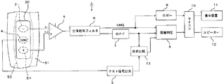
以下、本発明の第1実施の形態に係る筋評価システム1を図1と図2を用いて説明する。この筋評価システム1は、筋50が随意収縮する際に筋50の筋線維に沿って伝搬される筋活動電位を、筋50の体表面51に密着させる一組の生体電極2+、2-から検出し、増幅した筋活動電位が連続する筋電信号(以下、EMG信号という)から、筋50の異常や疲労の状態を評価するとともに、一組の生体電極2+、2-が体表面51に密着しているか否かの密着判定を行う。ここで、生体電極2が体表面51に密着しているとは、筋50の状態を評価するのに十分な筋活動電位が生体電極2に表れる程度に、生体電極2と体表面51が低接触抵抗で接触している状態をいい、以下、この密着している状態を正常接触と、筋50の状態を評価するのに十分な筋活動電位が生体電極2に表れない状態を、異常接触という。
一組の生体電極2+、2-は、筋50の筋線維に沿って体表面51へ密着させるように、細長の絶縁シート30の長手方向の両側に取り付けられ、それぞれ絶縁シート30の体表面51に対向する側の裏面30aに電極面を露出させている。一組の生体電極2+、2-はそれぞれ差動増幅回路を構成するオペアンプ5の非反転入力5+と反転入力5-に接続し、オペアンプ5は、一組の生体電極2+、2-に表れる筋活動電位や後述するコモンモードテスト信号の電位の差分を増幅して出力する。従って、オペアンプ5は、非反転入力5+と反転入力5-に同相で同一レベルで入力される信号をその出力から除く、コモンモード除去機能を有している。
絶縁シート30の一組の生体電極2+、2-が取り付けられた中間には、テスト信号出力回路3からコモンモードテスト信号が出力されるコモン電極4が取り付けられている。コモン電極4もその電極面を、絶縁シート30の裏面30aに露出させているが、その露出位置は、上記オペアンプ5のオフセット電圧Vosに応じて調整している。すなわち、体表面51に密着するコモン電極4と生体電極2+間と、コモン電極4と生体電極2-間の距離をわずかに異ならせて、コモンモードテスト信号が流れるこれらの間のインピーダンスを異ならせ、各生体電極2+、2-に表れるコモンモードテスト信号の電位差が、オペアンプ5のオフセット電圧Vosに相当する電位差に一致するように、コモン電極4の露出位置を一組の生体電極2+、2-のいずれか側に偏らせる。これにより、オペアンプ5の非反転入力5+と反転入力5-に入力される筋活動電位やコモンモードテスト信号は、オペアンプ5の内部誤差の影響を受けずに、その差分が増幅されて出力される。
また、コモン電極4は、一組の生体電極2+、2-より厚く、一組の生体電極2+、2-が絶縁シート30の裏面30aに露出する位置より更に図2に示す下方に突出して露出し、内方に押し込んだ体表面51に接触させている。これにより、コモン電極4から体表面51へ確実にコモンモードテスト信号を流した状態で、一組の生体電極2+、2-に表れるコモンモードテスト信号の信号強度から、生体電極2+、2-の体表面51への接触状態を判定できる。
テスト信号出力回路3は、被験者に刺激を与えない電圧と電流のコモンモードテスト信号を出力し、ここでは、0.3mVで、体表面51のインピーダンスを2kΩとした場合に150nA程度の電流が流れるコモンモードテスト信号をコモン電極4へ出力する。コモンモードテスト信号の周波数は、一組の生体電極2+、2-に表れる信号から検出可能とするために、予め定めた所定の周波数とし、ここでは、筋50が随意収縮する際に発生する筋活動電位から検出されるEMG信号が概ね1kHz以下であり、EMG信号を通過させる生体信号フィルタ6にコモンモードテスト信号も通過させるように、加えて、商用交流電源線から生じるコモンモードノイズの周波数と識別して抽出できるように、20Hzとしている。
オペアンプ5の出力に接続する生体信号フィルタ6は、上述のように、オペアンプ5の出力信号から1kHz以下の周波数のEMG信号とコモンモードテスト信号を含む出力信号を通過させ、ロガー8、接触判定回路9及び20Hzの帯域フィルタ7に出力している。ここで生体信号フィルタ6から出力されるEMG信号は、コモンモード除去機能を有するオペアンプ5から出力された信号であるが、筋活動電位は筋50の筋繊維に沿って伝搬し、一組の生体電極2+、2-には、位相が異なる筋活動電位が表れ、オペアンプ5の非反転入力5+と反転入力5-に入力されるので、オペアンプ5は、位相の異なる筋活動電位の差分を増幅したEMG信号を出力する。
ロガー8は、生体信号フィルタ6から出力される筋活動電位の差分を増幅したEMG信号を経過時間と共に記録し、マイコン10へ出力する。EMG信号の周波数、振幅やその変化は、筋50の収縮活動に依存し、例えば随意収縮する筋50の疲労が亢進すると、筋50の収縮性を補うための運動単位の動員数及び発火頻度が増加し、EMG信号の振幅も大きくなるので、マイコン10は、ロガー8から入力されるEMG信号とその経過時間による変化から、筋50の種々の活動を評価する。
マイコン10には、表示装置11とスピーカ12が接続され、マイコン10で評価した筋50の評価結果を表示装置11による表示及び/又はスピーカ12から発する音で、この筋評価システム1を利用する利用者へ伝える。例えば、表示措置11に複数のLEDが備えられ、マイコン10が評価した筋50の収縮力に応じた複数の段階毎にLEDの点灯数を異ならせたり、筋50の疲労が限界に達したとマイコン10が評価した場合に、スピーカ12から筋50の収縮運動の停止を促す音声が発せられる。
帯域フィルタ7は、生体信号フィルタ6の出力から更に20Hzの信号を通過させて、コモンモードテスト信号を抽出し、位相比較回路13と接触判定回路9へ出力する。位相回路9は、帯域フィルタ7から出力されるコモンモードテスト信号を、テスト信号出力回路3によるコモンモードテスト信号の出力タイミングと比較し、テスト信号出力回路3から出力されるコモンモードテスト信号と同相であるか逆相であるかを比較する。
すなわち、一組の生体電極2+、2-のうち、オペアンプ5の反転入力5-に接続する生体電極2-が体表面51に密着していない場合には、生体電極2+に表れるコモンモードテスト信号が反転入力5-に勝って非反転入力5+に入力されるので、オペアンプ5の出力に含まれるコモンモードテスト信号は、テスト信号出力回路3から出力されるコモンモードテスト信号と同相となり、位相比較回路13は、同相である比較結果を接触判定回路9へ出力する。一方、生体電極2+が体表面51に密着していない場合には、生体電極2-に表れるコモンモードテスト信号が非反転入力5+に勝って反転入力5-に入力されるので、オペアンプ5の出力に含まれるコモンモードテスト信号は、テスト信号出力回路3から出力されるコモンモードテスト信号と逆相となり、位相比較回路13は、逆相である比較結果を接触判定回路9へ出力する。
接触判定回路9は、生体信号フィルタ6から出力されるEMG信号と、帯域フィルタ7から出力されるコモンモードテスト信号と、位相比較回路13から出力される比較結果とから、一組の各生体電極2+、2-の体表面51への接触状態を判定するもので、以下、この接触判定回路9における接触状態の判定方法について詳述する。
(一組の生体電極2+、2-のいずれも、体表面51に正常接触している場合)
一組の生体電極2+、2-のいずれも、体表面51に正常接触している場合には一組の生体電極2+、2-の中間で体表面51に接触するコモン電極4から出力されるコモンモードテスト信号は、一組の生体電極2+、2-に同相でほぼ同一レベルで表れ、それぞれオペアンプ5の非反転入力5+と反転入力5-に入力されるので、オペアンプ5のコモンモード除去機能により、出力に表れない。その結果、帯域フィルタ7から出力されるコモンモードテスト信号の信号強度は所定の許容信号強度以下となる。
一方、コモンモードテスト信号と無関係に、体表面51に正常接触している生体電極2+、2-には、それぞれ位相の異なる表面筋活動電位が表れるので、オペアンプ5においてその筋活動電位の差分を増幅して生体信号フィルタ6から出力されるEMG信号は、所定の信号強度閾値を越え、接触判定回路9は、帯域フィルタ7から出力されるコモンモードテスト信号の信号強度が所定の許容信号強度以下で、生体信号フィルタ6から出力されるEMG信号が、所定の信号強度閾値を越えることから、一組の生体電極2+、2-のいずれも正常接触と判定する。
一組の生体電極2+、2-のいずれも、体表面51に正常接触している場合には一組の生体電極2+、2-の中間で体表面51に接触するコモン電極4から出力されるコモンモードテスト信号は、一組の生体電極2+、2-に同相でほぼ同一レベルで表れ、それぞれオペアンプ5の非反転入力5+と反転入力5-に入力されるので、オペアンプ5のコモンモード除去機能により、出力に表れない。その結果、帯域フィルタ7から出力されるコモンモードテスト信号の信号強度は所定の許容信号強度以下となる。
一方、コモンモードテスト信号と無関係に、体表面51に正常接触している生体電極2+、2-には、それぞれ位相の異なる表面筋活動電位が表れるので、オペアンプ5においてその筋活動電位の差分を増幅して生体信号フィルタ6から出力されるEMG信号は、所定の信号強度閾値を越え、接触判定回路9は、帯域フィルタ7から出力されるコモンモードテスト信号の信号強度が所定の許容信号強度以下で、生体信号フィルタ6から出力されるEMG信号が、所定の信号強度閾値を越えることから、一組の生体電極2+、2-のいずれも正常接触と判定する。
(一組の生体電極2+、2-のいずれも、体表面51に異常接触している場合)
一組の生体電極2+、2-のいずれも、体表面51に異常接触している場合には一組のいずれの生体電極2+、2-にもコモンモードテスト信号が表れず、オペアンプ5の非反転入力5+と反転入力5-にコモンモードテスト信号が入力されないので、オペアンプ5の出力にも表れない。その結果、帯域フィルタ7から出力されるコモンモードテスト信号の信号強度は所定の許容信号強度以下となる。
また、筋活動電位も一組の生体電極2+、2-に表れず、オペアンプ5の非反転入力5+と反転入力5-に入力されないので、生体信号フィルタ6から出力されるEMG信号は、所定の信号強度閾値以下となり、接触判定回路9は、帯域フィルタ7から出力されるコモンモードテスト信号の信号強度が所定の許容信号強度以下で、生体信号フィルタ6から出力されるEMG信号も、所定の信号強度閾値以下であることから、一組の生体電極2+、2-のいずれも異常接触と判定する。
一組の生体電極2+、2-のいずれも、体表面51に異常接触している場合には一組のいずれの生体電極2+、2-にもコモンモードテスト信号が表れず、オペアンプ5の非反転入力5+と反転入力5-にコモンモードテスト信号が入力されないので、オペアンプ5の出力にも表れない。その結果、帯域フィルタ7から出力されるコモンモードテスト信号の信号強度は所定の許容信号強度以下となる。
また、筋活動電位も一組の生体電極2+、2-に表れず、オペアンプ5の非反転入力5+と反転入力5-に入力されないので、生体信号フィルタ6から出力されるEMG信号は、所定の信号強度閾値以下となり、接触判定回路9は、帯域フィルタ7から出力されるコモンモードテスト信号の信号強度が所定の許容信号強度以下で、生体信号フィルタ6から出力されるEMG信号も、所定の信号強度閾値以下であることから、一組の生体電極2+、2-のいずれも異常接触と判定する。
(一組の生体電極2+、2-の一方のみが体表面51に正常接触している場合)
一組の生体電極2+、2-のいずれかが、体表面51に正常接触し、他方が異常接触している場合には正常接触しているいずれかの生体電極2+、2-にコモンモードテスト信号が表れ、オペアンプ5の非反転入力5+と反転入力5-の一方にのみコモンモードテスト信号入力されるので、帯域フィルタ7から出力されるコモンモードテスト信号の信号強度は所定の許容信号強度を越える。
接触判定回路9は、帯域フィルタ7から出力されるコモンモードテスト信号の信号強度が所定の許容信号強度を越え、位相比較回路13から同相である比較結果が入力された場合には、オペアンプ5の非反転入力5+に接続する生体電極2+が正常接触と、反転入力5-に接続する生体電極2-が非接触と判定する。
また、接触判定回路9は、帯域フィルタ7から出力されるコモンモードテスト信号の信号強度が所定の許容信号強度を越え、位相比較回路13から逆相である比較結果が入力された場合には、オペアンプ5の反転入力に接続する生体電極2-が正常接触と、非反転入力5+に接続する生体電極2+が非接触と判定する。
一組の生体電極2+、2-のいずれかが、体表面51に正常接触し、他方が異常接触している場合には正常接触しているいずれかの生体電極2+、2-にコモンモードテスト信号が表れ、オペアンプ5の非反転入力5+と反転入力5-の一方にのみコモンモードテスト信号入力されるので、帯域フィルタ7から出力されるコモンモードテスト信号の信号強度は所定の許容信号強度を越える。
接触判定回路9は、帯域フィルタ7から出力されるコモンモードテスト信号の信号強度が所定の許容信号強度を越え、位相比較回路13から同相である比較結果が入力された場合には、オペアンプ5の非反転入力5+に接続する生体電極2+が正常接触と、反転入力5-に接続する生体電極2-が非接触と判定する。
また、接触判定回路9は、帯域フィルタ7から出力されるコモンモードテスト信号の信号強度が所定の許容信号強度を越え、位相比較回路13から逆相である比較結果が入力された場合には、オペアンプ5の反転入力に接続する生体電極2-が正常接触と、非反転入力5+に接続する生体電極2+が非接触と判定する。
尚、オペアンプ5の非反転入力5+に接続する生体電極2+が正常接触し、反転入力5-に接続する生体電極2-が非接触である場合には、オペアンプ5から出力されるコモンモードテスト信号の信号電圧は、反転入力5-と非反転入力5+を短絡した場合のオペアンプ5の出力電圧を基準電圧として、基準電圧に、例えばオペアンプ5に入力されるコモンモードテスト信号の信号電圧の1/2とした所定の許容電圧誤差を加えた上限電圧以上となり、一方、オペアンプ5の非反転入力5+に接続する生体電極2+が異常接触し、反転入力5-に接続する生体電極2-が正常接触である場合には、基準電圧から許容電圧誤差を減じた下限電圧以下となる。
従って、帯域フィルタ7から出力されるコモンモードテスト信号の信号強度が所定の許容信号強度を越え、一組の生体電極2+、2-のいずれか一方が正常接触している場合に、接触判定回路9は、位相比較回路13の比較結果を用いずに、帯域フィルタ7から出力されるコモンモードテスト信号の信号電圧が上記上限電圧以上や下限電圧以下であるかを比較することからも、一組のいずれの生体電極2+、2-が異常接触であるかを判定できる。
従って、帯域フィルタ7から出力されるコモンモードテスト信号の信号強度が所定の許容信号強度を越え、一組の生体電極2+、2-のいずれか一方が正常接触している場合に、接触判定回路9は、位相比較回路13の比較結果を用いずに、帯域フィルタ7から出力されるコモンモードテスト信号の信号電圧が上記上限電圧以上や下限電圧以下であるかを比較することからも、一組のいずれの生体電極2+、2-が異常接触であるかを判定できる。
接触判定回路9は、一組の生体電極2+、2-のいずれか、若しくは双方が異常接触と判定すると、その判定結果をマイコン10へ出力し、マイコン10は、異常接触とした判定結果を表示装置11への表示及び/又はスピーカ12から発する音で利用者へ伝える。従って、筋50の体表面51に一組の生体電極2+、2-を密着させ、EMG信号から筋50を評価する前若しくは筋50を随意収縮させる運動中に、生体電極2+、2-の異常接触を利用者へ伝えることができ、生体電極2+、2-の再密着を促すことができる。
次に、本発明の第2の実施の形態に係る筋評価システム20を、図3乃至図8を用いて説明する。筋評価システム20の各部について、上述の筋評価システム1と同一若しくは同様に作用する構成には、同一の番号を用いてその詳細な説明を省略する。
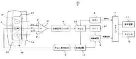
この筋評価システム20も、筋50が随意収縮する際に筋50の筋線維に沿って伝搬される筋活動電位を、筋50の体表面51に密着させる一組の生体電極2+、2-から検出するもので、筋評価システム1と異なり、絶縁シート30の裏面30aに電極面を露出させた一組の生体電極2+、2-とコモン電極4を、それぞれ非反転入力21+と反転入力21-とref入力21Rに接続した差動増幅回路21と、差動増幅回路21のアナログ出力をA/D変換するADコンバータ23と、ADコンバータ23でA/D変換した差動増幅回路21のEMG信号とコモンモードテスト信号を含む出力信号を、高速フーリエ変換し、周波数毎の信号強度を算出するFFTアナライザ22を備えている。
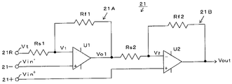
差動増幅回路21は、第1非反転増幅回路21Aと第1非反転増幅回路21Aの出力に第2入力抵抗Rs2を介して反転入力を接続させた第2非反転増幅回路21Bとから構成され、図4に示すように、差動増幅回路21の非反転入力21+と反転入力21-を、それぞれ第2オペアンプU2と第1オペアンプU1の非反転入力に接続し、一組の生体電極2+、2-に表れる電位Vin+とVin-をそれぞれ第2オペアンプU2と第1オペアンプU1の非反転入力に入力している。また、コモン電極4に接続する差動増幅回路21のref入力21Rは、反転入力抵抗Rs1を介して第1オペアンプU1の反転入力に接続し、コモン電極4に出力されるコモンモードテスト信号の信号電圧Vtを第1オペアンプU1の反転入力に入力している。
この差動増幅回路21では、第1非反転増幅回路21Aの第1入力抵抗Rs1に対する第1帰還抵抗Rf1の抵抗値の比をkとして、第2非反転増幅回路21Bの第2入力抵抗Rs2に対する第2帰還抵抗Rf2の抵抗値の比を、上記の比の逆数の1/kとしている。
これにより第1オペアンプU1の反転入力の電位をV1、第2オペアンプU2の反転入力の電位をV2とすると、第1非反転増幅回路21Aの出力電圧Vo1は、

第2非反転増幅回路21Bの出力電圧である差動増幅回路21の出力電圧Voutは、

となり、第1オペアンプU1の反転入力と非反転入力間と第2オペアンプU2の反転入力と非反転入力間は仮想短絡状態であるので、V1=Vin-、V2=Vin+として、(2)式のVo1に(1)式を代入すれば、

となる。
(3)式に示すように、差動増幅回路21は、非反転入力21+と反転入力21-に同相で入力されるVin+とVin-が同一レベルの信号をその出力から除く、コモンモード除去機能を有し、ref入力21Rに入力されるコモンモードテスト信号の信号電圧Vtに、一組の生体電極2+、2-に表れる電位Vin+とVin-の差分を(1+k)/kで増幅した電圧が加えられた出力信号を生体信号フィルタ6へ出力する。
本実施の形態では、(1+k)/kで表される差動増幅回路21の電圧利得Aを、1000とし、一組の生体電極2+、2-に表れるコモンモードテスト信号の信号電圧の差分が、0.2mVであるとすれば、差動増幅回路21から200mVの信号電圧のコモンモードテスト信号が出力される。
差動増幅回路21の出力に接続する生体信号フィルタ6は、差動増幅回路21の出力信号から1kHz以下の周波数のEMG信号とコモンモードテスト信号を含む出力信号を通過させ、その出力側に接続するADコンバータ23においてA/D変換し、FFTアナライザ22で算定可能なデジタル信号とする。
ここで、ADコンバータ23から出力されるデジタル信号である出力信号には、EMG信号とコモンモードテスト信号が含まれ、コモンモードテスト信号には、(3)式に示すように、ref入力21Rに入力されるコモンモードテスト信号と、一組の各生体電極2+、2-に表れるコモンモードテスト信号の信号電圧の差分を1000倍に増幅したコモンモードテスト信号の両者が含まれるが、一組の生体電極2+、2-が正常接触している状態では、一組の生体電極2+、2-に表れるコモンモードテスト信号の差分が0若しくは微少値であり、一組の生体電極2+、2-に表れるEMG信号の差分を1000倍に増幅してADコンバータ23から出力されるEMG信号に比べて、いずれのコモンモードテスト信号も無視できる程度に小さい。
一方、一組の生体電極2+、2-のいずれかが、体表面51に正常接触し、他方が異常接触している場合には、一組の生体電極2+、2-に表れるコモンモードテスト信号の信号電圧の差分が大きく、差動増幅回路21においてその差分が1000倍に増幅され、ADコンバータ23から出力される。
従って、一組の生体電極2+、2-が正常接触している限り、ADコンバータ23においてA/D変換された出力信号は、そのままEMG信号を表しているとみなすことができ、ロガー8に一時記憶され、マイコン10は、ロガー8に記憶されたEMG信号から、筋50の活動を評価し、その結果を表示装置11やスピーカ12で利用者へ伝える。一方、マイコン10が、後述するように接触判定回路9から一組の生体電極2+、2-の少なくといずれかが異常接触であるとの判定結果を受けたときには、ロガー8に記憶されたADコンバータ23の出力信号には無視できないコモンモードテスト信号が含まれるので、EMG信号とみなさず、その出力信号からは筋50の活動を評価しない。
ADコンバータ23の出力信号は、FFTアナライザ22と位相比較回路13へも出力され、FFTアナライザ22は、EMG信号とコモンモードテスト信号を含む帯域で、ADコンバータ23の出力信号を高速フーリエ変換し、周波数毎の信号強度を算出し、更に、そのうち20Hzのコモンモードテスト信号について算出した信号強度を接触判定回路9へ出力する。ここでFFTアナライザ22は、単位周波数幅(1Hz幅)あたりの信号電圧の二乗で算定するパワー値で、ADコンバータ23の出力信号の周波数毎の信号強度を表し、FFTアナライザ22で20Hzについて算定したパワー値をコモンモードテスト信号の信号強度とするが、ADコンバータ23から出力される20Hzのコモンモードテスト信号の信号電力や信号電圧を、コモンモードテスト信号の信号強度としてもよい。
尚、上述のように、FFTアナライザ22は、EMG信号の周波数毎の信号強度も算出するので、その算出結果をロガー8若しくはマイコン10へ出力し、マイコン10においてEMG信号の周波数毎の信号強度から、筋50の活動を評価することもできる。
上述の通り、ADコンバータ23から出力されるコモンモードテスト信号には、(3)式に示すように、差動増幅回路21のref入力21Rに入力されるコモンモードテスト信号が含まれ、一組の各生体電極2+、2-が正常接触していても、FFTアナライザ22から出力される20Hzのコモンモードテスト信号の信号強度は、0とならない。また、生体電極2+、2-が体表面51に完全に接触していなくても、生体電極2+、2-に表れるコモンモードテスト信号の信号レベルから筋50の活動を評価可能な信号強度を検出できれば十分であるので、接触判定回路9は、所定の許容信号強度を設定し、FFTアナライザ22から出力される20Hzのコモンモードテスト信号の信号強度がこの許容信号強度を超える場合にのみ、いずれかの生体電極2+、2-が異常接触であると判定する。
すなわち、接触判定回路9は、FFTアナライザ22から出力されるコモンモードテスト信号の信号強度が、許容信号強度を越える場合に、一組の各生体電極2+、2-のいずれか一方が正常接触、他方が異常接触と判定し、位相比較回路13の位相判定結果を参照していずれが異常接触であるかを判定する。
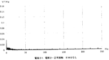
図6は、テスト信号出力回路3から20Hz、0.3mVのコモンモードテスト信号を出力し、筋50を随意収縮させずに、一組の生体電極2+、2-が正常接触している状態でのFFTアナライザ22から出力される出力図であり、差動増幅回路21のコモンモード除去機能により、FFTアナライザ22で算定された20Hzのコモンモードテスト信号の信号強度は、0.0017V2/Hzとなっている。一方、同一条件で、一組の一方の生体電極2-が異常接触する状態で、FFTアナライザ22から出力される出力図を示す図8においては、20Hz及びその逓倍の信号が顕著に表れ、20Hzのコモンモードテスト信号の信号強度は、0.0489V2/Hzとなっている。従って、例えば、許容信号強度をこの間の0.01V2/Hzに設定すれば、一組の生体電極2+、2-のいずれか一方の異常接触を判定できる。
しかしながら、コモンモードテスト信号の周波数を、EMG信号が存在する帯域中の20Hzに設定しているので、筋50が随意収縮している間は、ADコンバータ23から出力される20Hzの出力信号にコモンモードテスト信号とEMG信号が含まれ、EMG信号の信号強度と識別してコモンモードテスト信号の信号強度を算定することが困難となる。例えば、図6と同一条件で一組の生体電極2+、2-が正常接触し、筋50が随意収縮させた状態でFFTアナライザ22の出力を示す図6の出力図においては、図5に示す20Hzの0.0017V2/Hzのコモンモードテスト信号の信号強度に、20HzのEMG信号の信号強度が加わった0.0169V2/Hzとなり、許容信号強度を0.01V2/Hzと設定した場合には、筋50が随意収縮した場合に、一組の生体電極2+、2-のいずれか一方が異常接触と誤判定してしまう。
一方、図8と同一条件で一組の生体電極2+、2-の一方が異常接触し、筋50が随意収縮する状態でFFTアナライザ22から出力される図7に示す出力図では、20Hzの信号の信号強度は、EMG信号の信号強度が加わった0.0748V2/Hzであり、図8に示す0.0489V2/Hzより更に大きくなる。すなわち、FFTアナライザ22が算定するコモンモードテスト信号の信号周波数である20Hzの信号の信号強度は、筋50が随意収縮するか否かにかかわらず、一組の生体電極2+、2-の一方が異常接触している場合には、0.0489V2/Hz以上となり、一組のいずれの生体電極2+、2-も正常接触している場合には、0.0169V2/Hz以下となるので、この間に許容信号強度を設定すれば、筋50が随意収縮していても、一組の生体電極2+、2-の一方の異常接触を判定できる。
位相比較回路13は、ADコンバータ23から出力されるコモンモードテスト信号とテスト信号出力回路3から出力されるコモンモードテスト信号との位相を比較する。ADコンバータ23から出力に含まれるコモンモードテスト信号には、差動増幅回路21のref入力21Rに入力されるコモンモードテスト信号と、一組の各生体電極2+、2-に表れるコモンモードテスト信号の信号電圧の差分が差動増幅回路21において増幅されたコモンモードテスト信号の両者が含まれるが、接触判定回路9が位相比較回路13の比較結果を参照するいずれか一方の生体電極2+、2-が非接触である場合の前者のコモンモードテスト信号は、後者のコモンモードテスト信号に比べて無視できる程度に小さい。
従って、位相比較回路13は、一組の各生体電極2+、2-に表れるコモンモードテスト信号の信号電圧の差分を表すADコンバータ23から出力される増幅したコモンモードテスト信号を、テスト信号出力回路3から出力されるコモンモードテスト信号との位相を比較する。差動増幅回路21の非反転入力21+に接続する生体電極2+が正常接触、反転入力21-に接続する生体電極2-が異常接触である場合には、ADコンバータ23から出力されるコモンモードテスト信号は、テスト信号出力回路3から出力されるコモンモードテスト信号と同相となり、位相比較回路13は、同相の比較結果を接触判定回路9へ出力し、接触判定回路9は、FFTアナライザ22から出力されるコモンモードテスト信号の信号強度が、許容信号強度を越え、位相比較回路13から同相の比較結果が入力されることから、生体電極2+が正常接触、生体電極2-が異常接触と判定する。
一方、差動増幅回路21の非反転入力21+に接続する生体電極2+が異常接触、反転入力21-に接続する生体電極2-が正常接触である場合には、ADコンバータ23から出力されるコモンモードテスト信号は、テスト信号出力回路3から出力されるコモンモードテスト信号と逆相となり、位相比較回路13は、逆相の比較結果を接触判定回路9へ出力し、接触判定回路9は、FFTアナライザ22から出力されるコモンモードテスト信号の信号強度が、許容信号強度を越え、位相比較回路13から逆相の比較結果が入力されることから、生体電極2+が異常接触、生体電極2-が正常接触と判定する。
また、接触判定回路9は、FFTアナライザ22から出力されるコモンモードテスト信号の信号強度が、許容信号強度以下である場合には一組の生体電極2+、2-のいずれも正常接触またはいずれも異常接触と判定する。ここで、一組の各生体電極2+、2-のいずれも正常接触である場合には、一組の各生体電極2+、2-に位相の異なる表面筋活動電位が表れ、差動増幅回路21においてその差分を増幅した所定の信号強度のEMG信号が、ADコンバータ23からFFTアナライザ22へ出力される。逆に、一組の生体電極2+、2-のいずれも異常接触である場合には、各生体電極2+、2-に表面筋活動電位が表れず、差動増幅回路21とADコンバータ23を介してFFTアナライザ22へも所定の信号強度のEMG信号が表れない。
そこで、接触判定回路9は、FFTアナライザ22から出力されるコモンモードテスト信号の信号強度が、許容信号強度以下である場合に、FFTアナライザ22から出力されるEMG信号の周波数毎の信号強度を、EMG信号が存在する帯域(例えば0乃至250Hz)で積分し、更に、その積分値で表されるEMG信号の信号強度が所定値以上である場合に、一組の生体電極2+、2-のいずれも正常接触と、所定値未満である場合に一組の生体電極2+、2-のいずれも異常接触と判定する。
接触判定回路9による判定結果は、第1実施の形態と同様にマイコン10へ出力され、マイコン10は、その判定結果を表示装置11への表示及び/又はスピーカ12から発する音で利用者へ伝える。従って、いずれかの生体電極2+、2-が筋50の体表面51にを密着していない場合に、利用者は、異常接触の生体電極2+、2-について知ることができので、正常接触するように装着し直すことができる。
上述の各実施の形態では、筋50の体表面51に密着させる一組の生体電極2+、2-について、体表面51に密着している正常接触か、十分に密着していない異常接触かを判定したが、体表面51に密着させる3個以上の生体電極の各一組についてそれぞれコモンモード除去機能を有する差動増幅回路に接続し、各差動増幅回路の出力に含まれるコモンモードテスト信号の信号強度から、3個以上の生体電極の全てについて正常接触か、異常接触かを判定することもできる。
また、一組の生体電極2+、2-のいずれもが異常接触している状態や、一方のいずれの生体電極2+、2-が異常接触であるかまで、接触判定回路で判定しているが、一組の生体電極2+、2-が正常接触しているか、いずれかが異常接触しているかのみを判定するものであってもよい。
また、本発明は、筋が随意収縮する際の筋活動電位から筋の活動状態を評価する筋評価システムの例で説明したが、一定の電気刺激を加えて筋か発生する筋活動電位を体表面に密着させる生体電極から検出し、筋の活動状態を評価する筋評価システムであってもよい。
本発明は、一組の生体電極を筋の体表面に密着させて、筋の活動状態を評価する評価システムに適している。
1 第1実施の形態の筋評価システム
2+、2- 生体電極
3 テスト信号出力回路(テスト信号出力手段)
4 コモン電極
5 オペアンプ(差動増幅回路)
5- 反転入力
5+ 非反転入力
7 帯域フィルタ(信号抽出手段)
9 接触判定回路(密着判定手段)
13 位相比較回路
20 第2実施の形態の筋評価システム
21 差動増幅回路
21- 反転入力
21+ 非反転入力
21R ref入力
22 FFTアナライザ(信号抽出手段)
30 絶縁シート
30a 裏面
50 筋
51 体表面
2+、2- 生体電極
3 テスト信号出力回路(テスト信号出力手段)
4 コモン電極
5 オペアンプ(差動増幅回路)
5- 反転入力
5+ 非反転入力
7 帯域フィルタ(信号抽出手段)
9 接触判定回路(密着判定手段)
13 位相比較回路
20 第2実施の形態の筋評価システム
21 差動増幅回路
21- 反転入力
21+ 非反転入力
21R ref入力
22 FFTアナライザ(信号抽出手段)
30 絶縁シート
30a 裏面
50 筋
51 体表面
Claims (7)
- 体表面に対向する絶縁シートの裏面に露出する一組の生体電極と、
前記一組の生体電極をそれぞれ反転入力と非反転入力に接続し、反転入力と非反転入力の差分を増幅して出力する差動増幅回路とを備え、
前記一組の生体電極を体表面に密着させた状態で、前記一組の生体電極に表れる表面筋活動電位の差分を増幅して前記差動増幅回路から出力される筋電信号から前記一組の生体電極が密着する体表面内の筋の活動を評価する筋評価システムであって、
前記絶縁シートの裏面に露出して取り付けられ、前記一組の生体電極の中間で体表面に密着するコモン電極と、
前記コモン電極へ所定周波数のコモンモードテスト信号を出力するテスト信号出力手段と、
前記差動増幅回路の出力から前記所定周波数のコモンモードテスト信号を抽出する信号抽出手段と、
前記信号抽出手段で抽出したコモンモードテスト信号の信号強度が、所定の許容信号強度を越える場合に、いずれかの生体電極が体表面に密着していないと判定する密着判定手段とを、
更に備えることを特徴とする筋評価システム。 - 密着判定手段は、前記信号抽出手段で抽出したコモンモードテスト信号の信号強度が、前記許容信号強度以下であり、前記差動増幅回路から出力される前記筋電信号の信号強度が、所定の信号強度閾値以下である場合に、一組のいずれの生体電極も体表面に密着していないと判定することを特徴とする請求項1に記載の筋評価システム。
- 前記信号抽出手段で抽出したコモンモードテスト信号と前記テスト信号出力手段が出力したコモンモードテスト信号の位相を比較する位相比較回路を更に備え、
前記密着判定手段は、前記信号抽出手段で抽出したコモンモードテスト信号の信号強度が前記許容信号強度を越え、該コモンモードテスト信号の位相が、テスト信号出力手段が出力したコモンモードテスト信号と同相である場合に前記差動増幅回路の反転入力に接続する一方の生体電極が体表面に密着していないと、テスト信号出力手段が出力したコモンモードテスト信号と逆相である場合に前記差動増幅回路の非反転入力に接続する他方の生体電極が体表面に密着していないと、判定することを特徴とする請求項1に記載の筋評価システム。 - 前記密着判定手段は、前記反転入力と前記非反転入力を短絡した場合に前記差動増幅回路の出力電圧を基準電圧として、前記差動増幅回路から出力されるコモンモードテスト信号の信号電圧が、基準電圧に所定の許容電圧誤差を加えた上限電圧以上である場合に、前記差動増幅回路の非反転入力に接続する一方の生体電極が体表面に密着していないと、基準電圧から前記許容電圧誤差を減じた下限電圧以下である場合に前記差動増幅回路の反転入力に接続する他方の生体電極が体表面に密着していないと、判定することを特徴とする請求項1に記載の筋評価システム。
- 前記コモン電極は、一組の前記生体電極より絶縁シートの裏面から突出する状態で露出することを特徴とする請求項1乃至請求項4のいずれか1項に記載の筋評価システム。
- 前記絶縁シートの裏面に露出する前記コモン電極から前記一組の各生体電極までの距離を異ならせ、コモンモードテスト信号が流れることによる前記コモン電極と前記一組の各生体電極間の電位差を前記差動増幅回路のオフセット電圧とすることを特徴とする請求項1乃至請求項5のいずれか1項に記載の筋評価システム。
- 前記信号抽出手段は、前記筋電信号を含む前記差動増幅回路の出力から前記所定周波数のコモンモードテスト信号を抽出することを特徴とする請求項1乃至請求項6のいずれか1項に記載の筋評価システム。
Applications Claiming Priority (2)
| Application Number | Priority Date | Filing Date | Title |
|---|---|---|---|
| JP2018-122641 | 2018-06-28 | ||
| JP2018122641A JP6575642B1 (ja) | 2018-06-28 | 2018-06-28 | 筋評価システム |
Publications (1)
| Publication Number | Publication Date |
|---|---|
| WO2020003976A1 true WO2020003976A1 (ja) | 2020-01-02 |
Family
ID=67982824
Family Applications (1)
| Application Number | Title | Priority Date | Filing Date |
|---|---|---|---|
| PCT/JP2019/022752 Ceased WO2020003976A1 (ja) | 2018-06-28 | 2019-06-07 | 筋評価システム |
Country Status (3)
| Country | Link |
|---|---|
| JP (1) | JP6575642B1 (ja) |
| TW (1) | TW202000132A (ja) |
| WO (1) | WO2020003976A1 (ja) |
Citations (6)
| Publication number | Priority date | Publication date | Assignee | Title |
|---|---|---|---|---|
| JPH1028680A (ja) * | 1996-04-12 | 1998-02-03 | Siemens Elema Ab | 測定電極と中性電極およびそれらのリード線を監視する装置 |
| US20080027338A1 (en) * | 2006-02-28 | 2008-01-31 | Lu Zhong Q | Electrocardiogram Monitoring |
| JP2010538775A (ja) * | 2007-09-21 | 2010-12-16 | メドテック エイ/エス | 電極の接続状態の監視 |
| JP2016538022A (ja) * | 2013-10-23 | 2016-12-08 | ブレイン センティネル インコーポレイテッドBrain Sentinel,Inc. | 緩い電極のモニタリングを含む発作の検出 |
| JP2017217443A (ja) * | 2016-06-07 | 2017-12-14 | 学校法人梅村学園 | 筋状態測定シート |
| JP2017217189A (ja) * | 2016-06-07 | 2017-12-14 | Smk株式会社 | 筋状態測定シート |
-
2018
- 2018-06-28 JP JP2018122641A patent/JP6575642B1/ja active Active
- 2018-08-21 TW TW107129109A patent/TW202000132A/zh unknown
-
2019
- 2019-06-07 WO PCT/JP2019/022752 patent/WO2020003976A1/ja not_active Ceased
Patent Citations (6)
| Publication number | Priority date | Publication date | Assignee | Title |
|---|---|---|---|---|
| JPH1028680A (ja) * | 1996-04-12 | 1998-02-03 | Siemens Elema Ab | 測定電極と中性電極およびそれらのリード線を監視する装置 |
| US20080027338A1 (en) * | 2006-02-28 | 2008-01-31 | Lu Zhong Q | Electrocardiogram Monitoring |
| JP2010538775A (ja) * | 2007-09-21 | 2010-12-16 | メドテック エイ/エス | 電極の接続状態の監視 |
| JP2016538022A (ja) * | 2013-10-23 | 2016-12-08 | ブレイン センティネル インコーポレイテッドBrain Sentinel,Inc. | 緩い電極のモニタリングを含む発作の検出 |
| JP2017217443A (ja) * | 2016-06-07 | 2017-12-14 | 学校法人梅村学園 | 筋状態測定シート |
| JP2017217189A (ja) * | 2016-06-07 | 2017-12-14 | Smk株式会社 | 筋状態測定シート |
Also Published As
| Publication number | Publication date |
|---|---|
| TW202000132A (zh) | 2020-01-01 |
| JP2020000477A (ja) | 2020-01-09 |
| JP6575642B1 (ja) | 2019-09-18 |
Similar Documents
| Publication | Publication Date | Title |
|---|---|---|
| EP2086403B1 (en) | Ecg electrode contact quality measurement system | |
| KR100825888B1 (ko) | 전극 동잡음 보상 회로 및 전극 동잡음 보상 방법 | |
| JP3980702B2 (ja) | 測定電極と中性電極およびそれらのリード線を監視する装置 | |
| KR101947676B1 (ko) | 생체 신호를 측정하는 장치 및 방법 | |
| JP6565002B2 (ja) | 生体信号取得装置および生体信号取得方法 | |
| EP3209197B1 (en) | Simultaneous impedance testing method and apparatus | |
| SE464557B (sv) | Saett och anordning vid elektromyografi | |
| CN114431863B (zh) | 用于测量电极接触阻抗的系统及阻抗测量方法 | |
| US8493072B2 (en) | Method and apparatus for detecting a short circuit | |
| Degen et al. | Enhancing interference rejection of preamplified electrodes by automated gain adaption | |
| CN103796580B (zh) | 生物信号测量装置 | |
| JP6575642B1 (ja) | 筋評価システム | |
| JP6984315B2 (ja) | 生体信号測定装置、接触状態判定システム | |
| EP3202319A1 (en) | Method for detecting position of signal source in living body, and device for detecting position of signal source in living body | |
| KR20140144009A (ko) | 생체 신호 측정 장치 | |
| Sarvaiya et al. | An impedance detector for glottography | |
| WO2018102855A1 (en) | Bioamplifier and impedance measurement system | |
| US9936893B2 (en) | Device for detecting electric potentials | |
| JP7345472B2 (ja) | 双方向センサ回路 | |
| US20160113532A1 (en) | Device for detecting electric potentials | |
| Desa et al. | Development of EMG circuit for detection of leg movement | |
| Garay et al. | An electromyography signal conditioning circuit simulation experience | |
| CN216933232U (zh) | 一种心理在线动态监测辅助装置 | |
| CN204671157U (zh) | 基于四电极的入体式血液阻抗测量系统 | |
| Tanaka et al. | Development of the EEG measurement technique under exercising |
Legal Events
| Date | Code | Title | Description |
|---|---|---|---|
| 121 | Ep: the epo has been informed by wipo that ep was designated in this application |
Ref document number: 19825157 Country of ref document: EP Kind code of ref document: A1 |
|
| NENP | Non-entry into the national phase |
Ref country code: DE |
|
| 122 | Ep: pct application non-entry in european phase |
Ref document number: 19825157 Country of ref document: EP Kind code of ref document: A1 |