WO2020004029A1 - Control device, method, and program - Google Patents
Control device, method, and program Download PDFInfo
- Publication number
- WO2020004029A1 WO2020004029A1 PCT/JP2019/023232 JP2019023232W WO2020004029A1 WO 2020004029 A1 WO2020004029 A1 WO 2020004029A1 JP 2019023232 W JP2019023232 W JP 2019023232W WO 2020004029 A1 WO2020004029 A1 WO 2020004029A1
- Authority
- WO
- WIPO (PCT)
- Prior art keywords
- shooting
- photographing
- control unit
- image
- unit
- Prior art date
- Legal status (The legal status is an assumption and is not a legal conclusion. Google has not performed a legal analysis and makes no representation as to the accuracy of the status listed.)
- Ceased
Links
Images











Classifications
-
- H—ELECTRICITY
- H04—ELECTRIC COMMUNICATION TECHNIQUE
- H04N—PICTORIAL COMMUNICATION, e.g. TELEVISION
- H04N23/00—Cameras or camera modules comprising electronic image sensors; Control thereof
- H04N23/60—Control of cameras or camera modules
- H04N23/68—Control of cameras or camera modules for stable pick-up of the scene, e.g. compensating for camera body vibrations
- H04N23/682—Vibration or motion blur correction
- H04N23/685—Vibration or motion blur correction performed by mechanical compensation
- H04N23/687—Vibration or motion blur correction performed by mechanical compensation by shifting the lens or sensor position
-
- G—PHYSICS
- G05—CONTROLLING; REGULATING
- G05D—SYSTEMS FOR CONTROLLING OR REGULATING NON-ELECTRIC VARIABLES
- G05D1/00—Control of position, course, altitude or attitude of land, water, air or space vehicles, e.g. using automatic pilots
- G05D1/0094—Control of position, course, altitude or attitude of land, water, air or space vehicles, e.g. using automatic pilots involving pointing a payload, e.g. camera, weapon, sensor, towards a fixed or moving target
-
- B—PERFORMING OPERATIONS; TRANSPORTING
- B64—AIRCRAFT; AVIATION; COSMONAUTICS
- B64C—AEROPLANES; HELICOPTERS
- B64C13/00—Control systems or transmitting systems for actuating flying-control surfaces, lift-increasing flaps, air brakes, or spoilers
- B64C13/02—Initiating means
- B64C13/16—Initiating means actuated automatically, e.g. responsive to gust detectors
- B64C13/18—Initiating means actuated automatically, e.g. responsive to gust detectors using automatic pilot
-
- B—PERFORMING OPERATIONS; TRANSPORTING
- B64—AIRCRAFT; AVIATION; COSMONAUTICS
- B64C—AEROPLANES; HELICOPTERS
- B64C39/00—Aircraft not otherwise provided for
- B64C39/02—Aircraft not otherwise provided for characterised by special use
- B64C39/024—Aircraft not otherwise provided for characterised by special use of the remote controlled vehicle type, i.e. RPV
-
- B—PERFORMING OPERATIONS; TRANSPORTING
- B64—AIRCRAFT; AVIATION; COSMONAUTICS
- B64D—EQUIPMENT FOR FITTING IN OR TO AIRCRAFT; FLIGHT SUITS; PARACHUTES; ARRANGEMENT OR MOUNTING OF POWER PLANTS OR PROPULSION TRANSMISSIONS IN AIRCRAFT
- B64D47/00—Equipment not otherwise provided for
- B64D47/08—Arrangements of cameras
-
- B—PERFORMING OPERATIONS; TRANSPORTING
- B64—AIRCRAFT; AVIATION; COSMONAUTICS
- B64U—UNMANNED AERIAL VEHICLES [UAV]; EQUIPMENT THEREFOR
- B64U10/00—Type of UAV
- B64U10/10—Rotorcrafts
- B64U10/13—Flying platforms
-
- G—PHYSICS
- G03—PHOTOGRAPHY; CINEMATOGRAPHY; ANALOGOUS TECHNIQUES USING WAVES OTHER THAN OPTICAL WAVES; ELECTROGRAPHY; HOLOGRAPHY
- G03B—APPARATUS OR ARRANGEMENTS FOR TAKING PHOTOGRAPHS OR FOR PROJECTING OR VIEWING THEM; APPARATUS OR ARRANGEMENTS EMPLOYING ANALOGOUS TECHNIQUES USING WAVES OTHER THAN OPTICAL WAVES; ACCESSORIES THEREFOR
- G03B15/00—Special procedures for taking photographs; Apparatus therefor
-
- G—PHYSICS
- G03—PHOTOGRAPHY; CINEMATOGRAPHY; ANALOGOUS TECHNIQUES USING WAVES OTHER THAN OPTICAL WAVES; ELECTROGRAPHY; HOLOGRAPHY
- G03B—APPARATUS OR ARRANGEMENTS FOR TAKING PHOTOGRAPHS OR FOR PROJECTING OR VIEWING THEM; APPARATUS OR ARRANGEMENTS EMPLOYING ANALOGOUS TECHNIQUES USING WAVES OTHER THAN OPTICAL WAVES; ACCESSORIES THEREFOR
- G03B37/00—Panoramic or wide-screen photography; Photographing extended surfaces, e.g. for surveying; Photographing internal surfaces, e.g. of pipe
-
- G—PHYSICS
- G05—CONTROLLING; REGULATING
- G05D—SYSTEMS FOR CONTROLLING OR REGULATING NON-ELECTRIC VARIABLES
- G05D1/00—Control of position, course, altitude or attitude of land, water, air or space vehicles, e.g. using automatic pilots
- G05D1/04—Control of altitude or depth
- G05D1/06—Rate of change of altitude or depth
- G05D1/0607—Rate of change of altitude or depth specially adapted for aircraft
-
- G—PHYSICS
- G05—CONTROLLING; REGULATING
- G05D—SYSTEMS FOR CONTROLLING OR REGULATING NON-ELECTRIC VARIABLES
- G05D1/00—Control of position, course, altitude or attitude of land, water, air or space vehicles, e.g. using automatic pilots
- G05D1/40—Control within particular dimensions
- G05D1/46—Control of position or course in three dimensions [3D]
-
- H—ELECTRICITY
- H04—ELECTRIC COMMUNICATION TECHNIQUE
- H04N—PICTORIAL COMMUNICATION, e.g. TELEVISION
- H04N23/00—Cameras or camera modules comprising electronic image sensors; Control thereof
- H04N23/60—Control of cameras or camera modules
-
- H—ELECTRICITY
- H04—ELECTRIC COMMUNICATION TECHNIQUE
- H04N—PICTORIAL COMMUNICATION, e.g. TELEVISION
- H04N23/00—Cameras or camera modules comprising electronic image sensors; Control thereof
- H04N23/60—Control of cameras or camera modules
- H04N23/65—Control of camera operation in relation to power supply
-
- H—ELECTRICITY
- H04—ELECTRIC COMMUNICATION TECHNIQUE
- H04N—PICTORIAL COMMUNICATION, e.g. TELEVISION
- H04N23/00—Cameras or camera modules comprising electronic image sensors; Control thereof
- H04N23/60—Control of cameras or camera modules
- H04N23/68—Control of cameras or camera modules for stable pick-up of the scene, e.g. compensating for camera body vibrations
- H04N23/681—Motion detection
- H04N23/6811—Motion detection based on the image signal
-
- H—ELECTRICITY
- H04—ELECTRIC COMMUNICATION TECHNIQUE
- H04N—PICTORIAL COMMUNICATION, e.g. TELEVISION
- H04N23/00—Cameras or camera modules comprising electronic image sensors; Control thereof
- H04N23/60—Control of cameras or camera modules
- H04N23/695—Control of camera direction for changing a field of view, e.g. pan, tilt or based on tracking of objects
-
- B—PERFORMING OPERATIONS; TRANSPORTING
- B64—AIRCRAFT; AVIATION; COSMONAUTICS
- B64U—UNMANNED AERIAL VEHICLES [UAV]; EQUIPMENT THEREFOR
- B64U2101/00—UAVs specially adapted for particular uses or applications
- B64U2101/30—UAVs specially adapted for particular uses or applications for imaging, photography or videography
-
- B—PERFORMING OPERATIONS; TRANSPORTING
- B64—AIRCRAFT; AVIATION; COSMONAUTICS
- B64U—UNMANNED AERIAL VEHICLES [UAV]; EQUIPMENT THEREFOR
- B64U2201/00—UAVs characterised by their flight controls
- B64U2201/20—Remote controls
-
- H—ELECTRICITY
- H04—ELECTRIC COMMUNICATION TECHNIQUE
- H04N—PICTORIAL COMMUNICATION, e.g. TELEVISION
- H04N5/00—Details of television systems
- H04N5/14—Picture signal circuitry for video frequency region
- H04N5/144—Movement detection
Definitions
- the present technology relates to a control device, a method, and a program, and more particularly, to a control device, a method, and a program capable of performing shooting under optimal shooting conditions.
- Patent Document 1 proposes a camera unit for mapping a situation of land as a camera unit for mounting a drone.
- the present technology has been made in view of such a situation, and is to enable shooting under optimal shooting conditions.
- a control device includes a control unit that corrects a preset photographing condition based on an analysis result of an image photographed by a photographing device provided on a moving body, and a control unit that corrects the photographing condition based on the corrected photographing condition.
- a drive control unit for controlling the driving of the moving body.
- a preset photographing condition is corrected based on an analysis result of an image photographed by a photographing device provided on a moving body.
- the driving of the moving body is controlled based on the corrected photographing condition.
- FIG. 1 is a diagram illustrating a moving object control system to which the present technology is applied.
- FIG. 4 is a diagram illustrating a flow of a shooting process.
- FIG. 4 is a diagram illustrating a detailed example of a shooting condition. It is a figure showing an example of a photography range and a photography route.
- FIG. 3 is a diagram illustrating an example of a shooting location, a shooting interval, a shooting altitude, and a moving speed. It is a figure showing an example of an amount of overlap.
- FIG. 3 is a block diagram illustrating a configuration example of a moving object.
- FIG. 9 is a diagram illustrating an example in which a photographing altitude is corrected by analyzing a band of a photographed image.
- FIG. 9 is a flowchart illustrating a control process of FIG. 8.
- FIG. 4 is a diagram illustrating an example of a relationship between a band of a captured image and a shooting altitude.
- FIG. 7 is a diagram illustrating an example of correcting an overlap amount by analyzing a band of a captured image.
- FIG. 4 is a diagram schematically illustrating a range captured by a lens in a single shutter. It is a figure which shows typically the range taken in by the lens in the continuous several times of a shutter. It is a flowchart explaining the control process of FIG.
- FIG. 6 is a diagram illustrating an example of a relationship between a band of a captured image and an overlap amount.
- FIG. 4 is a diagram illustrating an example of a relationship between a band of a captured image and a shooting altitude.
- FIG. 7 is a diagram illustrating an example of correcting an overlap amount by analyzing a band of a captured image.
- FIG. 4 is a diagram schematic
- FIG. 9 is a diagram illustrating an example of correcting a moving speed by analyzing a blur amount of a captured image.
- 17 is a flowchart illustrating a control process of FIG. 16.
- FIG. 9 is a diagram illustrating an example of a relationship between an image blur amount and a moving speed.
- FIG. 9 is a diagram illustrating an example in which a photographing route is corrected by determining the success or failure of photographing of a photographed image.
- 20 is a flowchart illustrating a control process in FIG. 19.
- FIG. 11 is a diagram illustrating an example in which a photographing altitude or a moving speed is corrected by analyzing remaining power of a moving object.
- 22 is a flowchart illustrating a control process of FIG. 21.
- FIG. 21 is a flowchart illustrating a control process of FIG. 21.
- FIG. 6 is a diagram illustrating a relationship between a band of a captured image and a shooting altitude.
- FIG. 9 is a diagram illustrating a relationship between a predicted remaining power amount and a correction amount when photographing is completed.
- FIG. 21 is a block diagram illustrating another example of a mobile object control system to which the present technology is applied.
- FIG. 9 is a diagram illustrating an example of correcting a shooting range by analyzing power of two moving objects.
- 27 is a flowchart illustrating a control process of FIG. 26. It is a figure which shows the relationship of the residual electric power prediction amount at the time of imaging completion of two moving bodies.
- FIG. 11 is a diagram illustrating a configuration example of a computer.
- FIG. 1 is a diagram illustrating a moving object control system to which the present technology is applied.
- the moving object control system 1 includes a moving object 11 having an imaging unit 21 such as a camera.
- the mobile object 11 shown in FIG. 1 is a so-called drone which is an aircraft capable of unmanned flight.
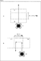
- a mobile body that can move autonomously, such as a robot, a car, or a trolley, may be used as the mobile body 11.
- ⁇ When photographing a certain area using the moving body 11, it is necessary to determine a photographing plan in advance.
- a user specifies a desired shooting resolution and a shooting area, so that shooting conditions such as a route and a shooting location are set.
- the moving body 11 controls the photographing unit 21 to photograph the subject while moving based on the set photographing conditions.
- the moving body 11 corrects the preset photographing conditions based on the analysis result of the image photographed by the photographing unit 21. In the moving body 11, movement and shooting timing are controlled based on the corrected shooting conditions.
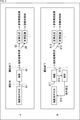
- FIG. 2 schematically shows a flow of a conventional moving object photographing process.
- a shooting condition is created before shooting, and then shooting is performed based on the created shooting condition as indicated by the tip of arrow # 1.
- the captured image is acquired by being taken in, for example, a PC as indicated by the arrow # 2, and a high-resolution image is generated by performing image synthesis as indicated by the arrow # 3.
- the control of the moving object is performed by performing the image recognition as indicated by the tip of arrow # 4.
- a moving object can only be photographed in accordance with a preset photographing condition. Therefore, for example, when it is not possible to take a picture according to the conditions due to disturbance such as a wind, an obstacle, or backlight, it is necessary to take a picture again or monitor a manned person.
- FIG. 2B schematically shows the flow of the photographing process in the mobile object control system 1 of FIG.
- a shooting condition is created before shooting, and then shooting is performed based on the created shooting condition, as indicated by the tip of arrow # 11.
- the captured image is acquired by being taken in, for example, a PC as shown by the arrow # 12, and a high-resolution image is generated by performing image synthesis as shown by the arrow # 13. You. Further, by performing the image recognition as shown at the tip of arrow # 14, the control of the moving body is performed.
- the flow of the photographing process shown in FIG. 2A is the same, but in the moving object control system 1, as shown at the end of arrow # 15, the analysis of the photographed image is completed before the photographing is completed. Done. Further, based on the analysis result, the photographing condition is corrected as indicated by the tip of arrow # 16. After the correction of the shooting conditions, shooting is performed based on the corrected shooting conditions.
- the mobile control system 1 it is possible to perform shooting under shooting conditions according to the situation at the time of shooting without re-taking the image.
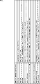
- FIG. 3 is a diagram illustrating an example of the photographing conditions.
- the shooting conditions include six shooting conditions for the moving object and two shooting conditions for the camera.
- the shooting conditions for the moving object include, for example, shooting altitude, shooting range, shooting route, shooting location, shooting speed, and overlap amount (side overlap amount).
- the shooting altitude is the shooting (flight) height from the ground (standard surface).
- the shooting range is the shooting target range (area).
- the shooting route is the flight order.
- the shooting route is usually set so as to cover the shooting range with one stroke.
- the photographing location is a position where the moving object is present while the shutter for photographing is opened and closed.
- the moving speed at the time of shooting is the moving speed or flying speed of the moving object at the time of shooting. If the moving speed during shooting is high, the shooting result may be blurred.
- the moving speed at the time of shooting is hereinafter referred to as a moving speed.
- the overlap amount is the amount of the overlapping range of the images to be synthesized when the moving body goes straight.
- the side overlap amount is the amount of the overlapping range of the images to be synthesized when the moving body bends.
- the amount of overlap and the amount of side overlap are represented by the ratio of how much overlap with the shooting range of one shutter.
- the photographing conditions for the camera include, for example, a photographed image storage resolution and a photographing exposure time.
- the captured image storage resolution is the number of pixels per unit area when a captured image is stored. The higher the captured image storage resolution, the more detailed objects can be described.
- the photographing exposure time is the shutter opening / closing time of one photographing. If the shooting exposure time is long, you can shoot brightly, but it is easy to shake.
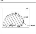
- FIG. 4 is a diagram showing an example of a shooting range and a shooting route as shooting conditions.
- FIG. 4 shows a map or aerial photograph of an area.
- the shooting range as the shooting condition in FIG. 3 is represented by a range surrounded by a broken line.
- the photographing path as the photographing condition in FIG. 3 is represented by a solid line connecting the photographing range and the vicinity of the edge with a single stroke.
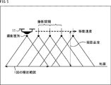
- FIG. 5 is a diagram illustrating an example of a shooting location, a shooting interval, a shooting altitude, and a moving speed as shooting conditions.
- FIG. 5 shows a state where the moving body 11 is photographing the ground.
- the shooting range of one shutter is represented by the base of the triangle.
- the shooting location under the shooting conditions in FIG. 3 is represented by a black circle at the vertex of the triangle.
- the shooting interval is represented between black circles.
- the shooting altitude under the shooting conditions in FIG. 3 is represented by an arrow from the moving body 11 to the ground.
- the moving speed under the photographing conditions in FIG. 3 is represented by an arrow pointing right from the moving body 11.
- FIG. 6 is a diagram showing an example of the amount of overlap.
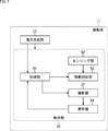
- FIG. 7 is a block diagram illustrating a configuration example of a moving object.
- the moving body 11 is composed of a power supply unit 51 and an operation unit 52.
- the power supply unit 51 includes a battery and a circuit for supplying power.
- the power supply unit 51 supplies power to the operation unit 52.
- the power supply unit 51 outputs information such as remaining power information to the operation unit 52.
- the remaining power information indicates the remaining power of the battery at the timing when the measurement is performed.
- the operation unit 52 includes a control unit 61, a sensing unit 62, a drive control unit 63, and an analysis unit 64 in addition to the above-described imaging unit 21. Each unit of the operation unit 52 operates with the power supplied from the power supply unit 51.
- the photographing unit 21 performs photographing based on the photographing instruction supplied from the control unit 61.
- the photographing unit 21 outputs a photographed image obtained by photographing to the analyzing unit 64.
- the control unit 61 is configured by a CPU, a ROM, a RAM, and the like, and controls the entire operation of the moving body 11 by executing a predetermined program.
- the control unit 61 creates shooting conditions for the mobile object 11 based on the input from the user and stores the shooting conditions in an internal memory.
- the control unit 61 corrects a preset photographing condition based on the analysis result of the image photographed by the photographing unit 21.
- control unit 61 calculates a correction value of the shooting condition for correcting the shooting condition based on the analysis result supplied from the analysis unit 64.
- the control unit 61 corrects the shooting conditions based on the calculated correction values, and outputs the corrected shooting conditions to the drive control unit 63.
- a method for example, among the photographing conditions, the photographing altitude, the photographing speed, the overlap amount, the photographing route, and the photographing range are corrected.
- the control unit 61 calculates a predicted remaining power amount at the end of all shooting. The control unit 61 corrects the shooting condition based on the calculated remaining power estimation amount.
- the sensing unit 62 includes various sensors for detecting altitude, attitude, speed, and the like.
- the sensing unit 62 outputs, to the drive control unit 63, sensing information indicating detection results such as altitude, attitude, and speed.
- the drive control unit 63 controls the driving of the moving body 11 based on the corrected photographing conditions. For example, the drive control unit 63 drives a motor or the like based on shooting conditions to move the moving body 11 to a desired position. When the moving body 11 is not operating according to the imaging conditions, the drive control unit 63 corrects the drive of the motor or the like using the sensing information supplied from the sensing unit 62.
- the analysis unit 64 analyzes the captured image supplied from the imaging unit 21 and outputs an analysis result such as a feature amount to the control unit 61.
- the analysis is performed in real time.
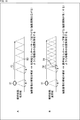
- FIG. 8 is a diagram illustrating an example in which the photographing altitude is corrected by analyzing the band of the photographed image.
- the analysis of the band of the captured image is performed by analyzing, for example, which frequency component is large as the spatial frequency of the captured image.
- a photographed image having a low band means that the image has a low frequency component and a gentle image
- a photographed image having a high band means that the image has a high frequency component and a fine image.
- the mobile unit 11 is corrected to increase the shooting altitude to the shooting altitude H1 (> H).
- the photographed image becomes an image having a lower resolution that cannot express fineness than the image at the photographing height H.
- the photographing range W1 > W
- the space P1 between the photographed places is also widened. Further, the number of photographing shutters is reduced, and the time required for photographing is reduced.
- the mobile body 11 is corrected to lower the shooting altitude to the shooting altitude H2 ( ⁇ H). .
- the shot image is an image having higher resolution that can be expressed more finely than the image at the shooting height H.
- the photographing range W2 ( ⁇ W) that can be photographed at one time becomes narrow. Further, the number of shooting shutters increases, and the time required for shooting increases.
- control for lowering the altitude may be performed in order to perform fine shooting.
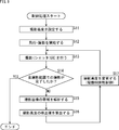
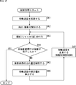
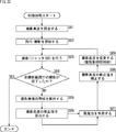
- step S11 the control unit 61 sets the shooting altitude.
- step S12 the drive control section 63 starts flying / photographing.
- step S13 the photographing unit 21 performs one photographing with the shutter.
- the photographing unit 21 outputs a photographed image obtained by photographing to the analyzing unit 64.
- step S14 the control unit 61 determines whether or not shooting in the entire shooting range has been completed. If it is determined in step S14 that shooting in the entire shooting range has not been completed, the process proceeds to step S15.
- step S15 the analysis unit 64 analyzes the band of the captured image.
- the analysis unit 64 outputs the analysis result of the band of the captured image to the control unit 61.
- step S16 the control unit 61 calculates a correction value for correcting the photographing altitude based on the analysis result.
- the correction value of the photographing altitude is calculated using a graph as shown in FIG.
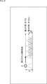
- FIG. 10 shows the relationship between the band of the photographed image and the photographing altitude. As shown in FIG. 10, as the band of the photographed image becomes higher, the photographing altitude becomes lower. For example, information indicating a relationship as shown in FIG. 10 preset by the user is stored in the memory of the control unit 61.
- the control unit 61 corrects the photographing altitude based on the correction value according to the analysis result of the band of the photographed image, and outputs the corrected photographing altitude to the drive control unit 63.
- step S17 the drive control unit 63 changes the shooting altitude based on the corrected shooting altitude supplied from the control unit 61.
- step S14 if it is determined in step S14 that the photographing in the entire photographing range has been completed, the control process ends.
- FIG. 11 is a diagram illustrating an example in which the overlap amount is corrected by analyzing the band of the captured image.
- the photographing by the moving body 11 is performed in one photographing range W, the overlap amount R, and the photographing interval P.
- the moving body 11 is modified to reduce the overlap amount R to the overlap amount R3 ( ⁇ R). You. In the case of FIG. 11A, the overlap amount R3 is almost zero.
- the captured image becomes an image having low resolution in which fineness cannot be expressed.
- the interval P3 between the imaging locations is also widened. Further, the number of photographing shutters is reduced, and the time required for photographing is reduced.
- the mobile unit 11 increases the overlap amount to the overlap amount R4 (> R). Will be modified.
- the shooting interval is controlled to be narrowed to the shooting interval P4 (> P).
- FIG. 12 is a diagram schematically showing a range captured by the lens in one shutter.
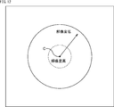
- ⁇ Circle around (1) ⁇ in FIG. 12 indicates a range captured by the lens in one shutter, and a circle indicated by a broken line indicates a region near the center point C of the captured image.
- the shooting resolution is high in an area near the center point. As indicated by the dashed circle, in a region near the center point C of the captured image, the imaging resolution is high and decreases toward the end. It should be noted that the degree of reduction in the shooting resolution differs depending on the lens characteristics.
- FIG. 13 is a diagram schematically showing a range captured by the lens in a plurality of successive times of the shutter.
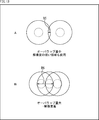
- FIG. 13 shows an overlap region of a range captured by the lens in a plurality of successive times of the shutter.
- the higher the overlap amount the higher the quality of the captured image can be obtained.
- step S21 the control unit 61 sets the amount of overlap.
- step S22 the drive control section 63 starts flying / photographing.
- step S23 the photographing unit 21 performs one photographing with the shutter.
- the photographing unit 21 outputs a photographed image obtained by photographing to the analyzing unit 64.
- step S24 the control unit 61 determines whether or not shooting in the entire shooting range has been completed. If it is determined in step S24 that shooting in the entire shooting range has not been completed, the process proceeds to step S25.
- step S25 the analysis unit 64 analyzes the band of the captured image.
- the analysis unit 64 outputs the analysis result of the band of the captured image to the control unit 61.
- step S26 the control unit 61 calculates a correction value for correcting the overlap amount based on the analysis result.
- the correction value of the overlap amount is calculated using a graph as shown in FIG.
- FIG. 15 shows the relationship between the band of the captured image and the amount of overlap. As shown in FIG. 15, as the band of the captured image becomes higher, the amount of overlap increases. For example, information indicating a relationship as shown in FIG. 15 preset by the user is stored in the memory of the control unit 61.
- the control unit 61 corrects the overlap amount based on the correction value according to the analysis result of the band of the captured image, and outputs the corrected overlap amount to the drive control unit 63.
- step S27 the drive control unit 63 changes the overlap amount based on the corrected overlap amount supplied from the control unit 61.
- step S24 if it is determined in step S24 that shooting in the entire shooting range has been completed, the control process ends.
- FIG. 16 is a diagram illustrating an example of correcting a moving speed by analyzing a blur amount of a captured image.
- Conditions that are likely to cause blurring in the captured image include when the brightness is low, when the wind is strong during flight, and when the aperture of the camera that constitutes the imaging unit is reduced (the depth of the subject is increased).
- the moving speed of the moving body 11 is set to the moving speed V1 ( ⁇ V). Modified to lower.
- the moving body 11 when the blur amount of the captured image by the moving body 11 that is shooting at the moving speed V is smaller than a predetermined threshold and the analysis result indicates that there is no blur, the moving body 11 Is modified to increase the moving speed to the moving speed V2 (> V).
- step S41 the control unit 61 sets a shooting speed.
- step S42 the drive control section 63 starts flying and photographing.
- step S43 the photographing section 21 performs one shutter photographing.
- the photographing unit 21 outputs a photographed image obtained by photographing to the analyzing unit 64.
- step S44 the control unit 61 determines whether or not shooting in the entire shooting range has been completed. If it is determined in step S44 that shooting in the entire shooting range has not been completed, the process proceeds to step S45.
- step S45 the analysis unit 64 analyzes the blur amount of the captured image by comparing it with a predetermined threshold.
- the analysis unit 64 outputs an analysis result of the blur amount of the captured image to the control unit 61.
- step S46 the control unit 61 calculates a correction value for correcting the shooting speed based on the analysis result.
- the correction value of the shooting speed is calculated using a graph as shown in FIG.
- FIG. 18 shows the relationship between the image blur amount and the moving speed. As shown in FIG. 18, as the blur amount of the captured image increases, the moving speed decreases. For example, information indicating a relationship as shown in FIG. 18 preset by the user is stored in the memory of the control unit 61.
- the control unit 61 corrects the moving speed based on a correction value according to the analysis result of the blur amount of the captured image, and outputs the corrected moving speed to the drive control unit 63.
- step S47 the drive control unit 63 changes the moving speed based on the corrected moving speed supplied from the control unit 61.
- step S44 if it is determined in step S44 that shooting in the entire shooting range has been completed, the control process ends.
- FIG. 19 is a diagram illustrating an example in which the photographing route is corrected by determining the success or failure of the photographed image.
- the photographing image success / failure judgment of the photographed image for example, when the blur amount of the photographed image exceeds a predetermined threshold, the result of the judgment is a photographing failure. If the blur amount of the captured image does not exceed the predetermined threshold, the determination result is that the image capture has succeeded.
- the photographing route of the moving body 11 is corrected so as to return to the previous photographing place and photograph again. You. At this time, the shooting altitude does not change. It should be noted that the present invention is not limited to the immediately preceding shooting location, and may return to the two preceding shooting location.
- the photographing path is corrected, and control is performed so that the moving body 11 is returned to the previous photographing position and photographed again.
- the time required for shooting can be reduced as compared with the related art in which a portion where shooting failed after all shooting is completed is re-shot.
- step S61 the control section 61 sets a photographing route.
- step S62 the drive control section 63 starts flying / photographing.
- step S63 the photographing unit 21 performs photographing with one shutter.
- the photographing unit 21 outputs a photographed image obtained by photographing to the analyzing unit 64.
- step S64 the control unit 61 determines whether or not shooting in the entire shooting range has been completed. If it is determined in step S64 that shooting in the entire shooting range has not been completed, the process proceeds to step S65.
- step S65 the analysis unit 64 analyzes the captured image.
- the analysis unit 64 outputs the analysis result of the captured image to the control unit 61.
- step S66 the control unit 61 determines the success or failure of the photographed image based on the analysis result to determine whether the photographing was successful. If it is determined in step S66 that the shooting has been successful, the process returns to step S63, and the subsequent processing is repeated.
- step S66 If it is determined in step S66 that the shooting has failed, the process proceeds to step S67.
- the control unit 61 corrects the shooting path of the shooting condition with the correction value of the shooting path that has been corrected so as to include the path to the immediately preceding shooting location, and outputs the corrected shooting path to the drive control unit 63. .
- step S67 the drive control unit 63 changes the destination (imaging route) to the immediately preceding imaging location based on the corrected imaging route supplied from the control unit 61, and performs imaging.
- FIG. 21 is a diagram illustrating an example in which the photographing altitude or the moving speed is corrected by analyzing the remaining power of the moving object.
- the photographing altitude of the moving body 11 is calculated to have the same value so as to continue moving at the photographing altitude H.
- a correction value of the shooting altitude is calculated.
- the remaining power is predicted.
- control based on the calculated imaging altitude is performed.
- the photographing altitude or the correction value of the photographing altitude is corrected based on the remaining power. As a result, it is possible to use the remaining power efficiently and perform shooting until the end.
- steps S81 to S85 in FIG. 22 are the same as the processes in steps S11 to S15 in FIG. Duplicate descriptions will be omitted as appropriate.
- step S86 the control unit 61 calculates a correction value of the photographing altitude based on the analysis result of the band of the photographed image.
- the correction value of the shooting altitude is calculated using a graph as shown in FIG.
- FIG. 23 shows the relationship between the band of the photographed image and the photographing altitude.
- the band of the captured image is divided into three ranges: a low band, a middle band, and a high band.
- the photographing altitude becomes higher as the band becomes lower.
- the middle band range the shooting altitude is constant.
- the photographing altitude becomes lower as the band becomes higher.
- Information indicating a relationship as shown in FIG. 23 preset by the user is stored in the memory of the control unit 61.
- step S87 the control unit 61 predicts the remaining power.
- step S88 the control unit 61 corrects the correction value of the shooting altitude based on the estimated remaining power.
- the correction of the correction value of the photographing altitude is performed, for example, by multiplying the correction value by the correction amount.
- the correction amount is calculated using a graph as shown in FIG.
- FIG. 24 shows the relationship between the remaining power prediction amount and the correction amount at the time of completion of shooting.
- the correction amount is set to 1.0.
- the correction amount also approaches 0 according to the predicted remaining power.
- Information indicating the relationship as shown in FIG. 24 is stored in the memory of the control unit 61.
- the control unit 61 multiplies the correction value of the photographing altitude according to the analysis result of the band of the photographed image by the correction amount to correct the photographing altitude of the photographing condition, and outputs the corrected photographing altitude to the drive control unit 63.
- step S89 the drive control unit 63 changes the shooting altitude based on the corrected shooting altitude supplied from the control unit 61.
- step S84 if it is determined in step S84 that the shooting in the entire shooting range has been completed, the control processing ends.
- FIG. 25 is a block diagram illustrating another example of a moving object control system to which the present technology is applied.
- the moving object control system 101 includes a moving object 111 and a control device 112. Parts corresponding to those in FIG. 7 are denoted by the same reference numerals.
- the configuration of the mobile control system 101 in FIG. 25 differs from the configuration in FIG. 7 in that the control unit 61 and the analysis unit 64 are provided in the control device 112. That is, the control of the moving body is not performed autonomously by the moving body, but is performed by the control device 112 which is an external device.
- the mobile object 111 and the control device 112 are provided with a receiving unit and a transmitting unit, respectively. Between the mobile unit 111 and the control device 112, the photographing conditions are transmitted at any time by wireless communication or the like. Note that there may be some transmission intervals, but in that case, a delay may occur and control accuracy may decrease.
- the moving body 111 includes a drone, a robot, a car, a trolley, and the like having the photographing unit 21 as in the case of the moving body 11 in FIG.
- the moving body 111 includes the power supply unit 51 and the operation unit 121.
- the operation unit 121 includes a transmission unit 131 and a reception unit 132 in addition to the above-described imaging unit 21, sensing unit 62, and drive control unit 63. Each unit of the operation unit 121 operates with the power supplied from the power supply unit 51.
- the transmission unit 131 transmits the captured image supplied from the imaging unit 21 and information such as remaining power information supplied from the power supply unit 51 to the control device 112.
- the receiving unit 132 receives the photographing condition transmitted from the control device 112 and outputs the photographing condition to the drive control unit 63.
- the receiving unit 132 receives the photographing instruction transmitted from the control device 112 and outputs it to the photographing unit 21.
- the control device 112 is configured by a personal computer, a tablet terminal, a smartphone, or the like.
- the control device 112 includes the control unit 61, the analysis unit 64, the reception unit 141, and the transmission unit 142 in FIG.
- the receiving unit 141 receives the captured image and the remaining power information transmitted from the moving body 111 and outputs the information to the analyzing unit 64.
- the transmission unit 142 transmits the imaging instruction supplied from the control unit 61 and information such as the imaging conditions supplied from the control unit 61 to the mobile unit 111.
- the correction of the photographing conditions as described above is performed by the control device 112.
- FIG. 26 is a diagram illustrating an example in which the photographing range is corrected by analyzing the remaining power of two moving objects.
- the entire photographing range is photographed by the two moving bodies 111A and 111B.
- the moving body 111A and the moving body 111B have the same configuration as that of the moving body 111 in FIG. Under the photographing conditions before photographing, the size of the photographing range of the moving body 111A is substantially the same as the size of the photographing range of the moving body 111B.
- the control device 112 analyzes the captured images from the moving bodies 111A and 111B, and calculates the correction values of the photographing altitude and the photographing speed based on the analysis result of the photographed images. Further, the control device 112 predicts the remaining power at the time of the completion of the imaging based on the remaining power information from the moving bodies 111A and 111B.
- the control device 112 calculates a correction value of the shooting range in which a part of the shooting range of the moving body 111A is reduced, as indicated by a white arrow in FIG.
- the control device 112 corrects the shooting range of the shooting condition with the calculated correction value of the shooting range, and transmits the corrected shooting range to the moving body 111A.
- the control device 112 calculates a correction value of the imaging range obtained by increasing a part of the imaging range of the moving body 111B.
- the control device 112 corrects the shooting range of the shooting condition with the calculated correction value of the shooting range, and transmits the corrected shooting range to the moving body 111B.
- step S111 the control unit 61 sets the photographing range of the moving body 111A and the moving body 111B.
- step S112 the drive control section 63 starts flying / photographing.
- step S113 the photographing section 21 performs one-time photographing with the shutter.
- the photographing unit 21 outputs a photographed image obtained by photographing to the analyzing unit 64.
- step S114 the control unit 61 determines whether or not each of the mobile object 111A and the mobile object 111B has completed shooting in the shooting range in charge. If it is determined in step S114 that shooting in the assigned shooting range has not been completed, the process proceeds to step S115.
- step S115 the analysis unit 64 analyzes the captured image.
- the analysis unit 64 outputs the analysis result of the captured image to the control unit 61.
- step S116 the control unit 61 controls the mobile unit 111A and the mobile unit 111B based on the analysis result. For example, among the photographing conditions, the photographing altitude, the moving speed, the overlap amount, and the like are controlled as described above.
- step S117 the control unit 61 predicts the remaining power based on the remaining power information from the moving bodies 111A and 111B.
- step S118 the control unit 61 calculates a correction value of the shooting range based on the remaining power prediction amount that is information indicating the remaining power predicted by the moving bodies 111A and 111B.
- the correction value of the imaging range is calculated based on the increase or decrease of the allocation of the imaging range to each of the moving bodies 111A and 111B.
- FIG. 28 shows the relationship between the estimated remaining power of the mobile unit 111A at the time of completion of imaging and the estimated amount of remaining power of the mobile unit 111B at the completion of imaging.
- the control unit 61 corrects the imaging ranges of the imaging conditions of the mobile object 111A and the mobile object 111B with the correction values of the imaging range calculated based on the estimated remaining power.
- step S119 the control unit 61 causes the drive control unit 63 of the moving body 111A and the moving body 111B to change the photographing range by transmitting the corrected shooting range to the moving body 111A and the moving body 111B, respectively.
- FIG. 27 an example in which the control method of FIG. 26 is performed by the mobile control system 101 of FIG. 25 has been described, but the control method of FIG. 26 may be performed by the mobile control system 1 of FIG.
- control methods of FIGS. 8, 11, 16, 19, and 21 which describe the example performed by the mobile control system 1 of FIG. 1 are executed by the mobile control system 101 of FIG. It may be made to be performed.
- a preset imaging condition is corrected from an analysis result of an image captured by an imaging device provided on a moving object, and driving of the moving object is performed based on the corrected imaging condition. Controlled.
- Computer> ⁇ Computer hardware configuration example>
- the series of processes described above can be executed by hardware or can be executed by software.
- a program constituting the software is installed in a computer.
- the computer includes a computer incorporated in dedicated hardware, a general-purpose personal computer that can execute various functions by installing various programs, and the like.
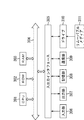
- FIG. 29 is a block diagram showing a configuration example of hardware of a computer that executes the above-described series of processing by a program.
- a CPU Central Processing UNIT
- ROM Read Only Memory
- RAM Random Access Memory
- the input / output interface 305 is further connected to the bus 304.
- the input unit 306, the output unit 307, the storage unit 308, the communication unit 309, and the drive 310 are connected to the input / output interface 305.
- the input unit 306 includes a keyboard, a mouse, a microphone, and the like.
- the output unit 307 includes a display, a speaker, and the like.
- the storage unit 308 includes a hard disk, a nonvolatile memory, and the like.
- the communication unit 309 includes a network interface and the like.
- the drive 310 drives a removable medium 311 such as a magnetic disk, an optical disk, a magneto-optical disk, or a semiconductor memory.
- the CPU 301 loads, for example, a program stored in the storage unit 308 into the RAM 303 via the input / output interface 305 and the bus 304 and executes the program. Is performed.
- the program executed by the computer (CPU 301) can be provided by being recorded on a removable medium 311 as a package medium or the like, for example. Further, the program can be provided via a wired or wireless transmission medium such as a local area network, the Internet, or digital satellite broadcasting.
- the program can be installed in the storage unit 308 via the input / output interface 305 by attaching the removable medium 311 to the drive 310. Further, the program can be received by the communication unit 309 via a wired or wireless transmission medium and installed in the storage unit 308. In addition, the program can be installed in the ROM 302 or the storage unit 308 in advance.
- the program executed by the computer may be a program in which processing is performed in chronological order according to the order described in this specification, or may be performed in parallel or at a necessary timing such as when a call is made. It may be a program that performs processing.
- a system refers to a set of a plurality of components (devices, modules (parts), and the like), and it does not matter whether all components are in the same housing. Therefore, a plurality of devices housed in separate housings and connected via a network, and one device housing a plurality of modules in one housing are all systems. .
- the present technology can adopt a configuration of cloud computing in which one function is shared by a plurality of devices via a network and processed jointly.
- each step described in the above-described flowchart can be executed by one device, or can be shared and executed by a plurality of devices.
- one step includes a plurality of processes
- the plurality of processes included in the one step may be executed by one device or may be shared and executed by a plurality of devices.
- the present technology can also have the following configurations.
- a control unit that corrects a preset photographing condition based on an analysis result of an image photographed by a photographing device provided in the moving body A drive control unit configured to control driving of the moving body based on the corrected imaging condition.
- the control device according to (1) further including: an analysis unit configured to analyze the image in real time.
- the control unit corrects the photographing condition based on an analysis result of a frequency component of the image, The control device according to (1) or (2), wherein the drive control unit changes a shooting altitude of the moving object based on the corrected shooting condition.
- the control unit corrects the photographing condition based on an analysis result of a frequency component of the image, The control device according to any one of (1) to (3), wherein the drive control unit changes a shooting interval of the moving object based on the corrected shooting condition.
- the control unit corrects the imaging condition based on the analysis result of the blur amount of the image, The control device according to (1) or (2), wherein the drive control unit changes the speed of the moving object based on the corrected imaging condition.
- the control unit corrects the imaging conditions based on an analysis result of analyzing whether the imaging of the image was successful or failed, The control device according to (1) or (2), wherein the drive control unit changes a shooting location of the moving body based on the corrected shooting conditions.
- the control unit based on the analysis result of the remaining power of the moving body, corrects the corrected imaging conditions, The control device according to any one of (1) to (6), wherein the drive control unit changes a shooting altitude or a speed of the moving object based on the corrected shooting conditions.
- the control unit corrects the imaging condition based on the analysis result of the remaining power of the plurality of moving objects, The control device according to (1) or (2), wherein the drive control unit changes a shooting range of the plurality of moving objects based on the corrected shooting condition.
- the control device is Correct the photographing conditions based on the analysis result of the image photographed by the photographing device provided on the moving body, A control method for controlling driving of the moving body based on the corrected photographing condition.
- a control unit that corrects a photographing condition based on an analysis result of an image photographed by a photographing device provided in the moving body A program that causes a computer to function as a drive control unit that controls driving of the moving object based on the corrected shooting conditions.
- 1 ⁇ mobile unit control system ⁇ 11 ⁇ mobile unit, ⁇ 51 ⁇ power supply unit, ⁇ 52 ⁇ operation unit, ⁇ 61 ⁇ control unit, ⁇ 62 ⁇ sensing unit, ⁇ 63 ⁇ drive control unit, ⁇ 64 ⁇ analysis unit, ⁇ 101 ⁇ mobile unit control system, ⁇ 111, 111A, 111B ⁇ mobile unit, 112 control device, ⁇ 121 ⁇ operation unit, ⁇ 131 ⁇ transmission unit, ⁇ 132 ⁇ reception unit, ⁇ 141 ⁇ reception unit, ⁇ 142 ⁇ transmission unit
Landscapes
- Engineering & Computer Science (AREA)
- Aviation & Aerospace Engineering (AREA)
- Remote Sensing (AREA)
- Physics & Mathematics (AREA)
- General Physics & Mathematics (AREA)
- Multimedia (AREA)
- Signal Processing (AREA)
- Automation & Control Theory (AREA)
- Radar, Positioning & Navigation (AREA)
- Mechanical Engineering (AREA)
- Studio Devices (AREA)
- Stereoscopic And Panoramic Photography (AREA)
Abstract
Description
本技術は、制御装置および方法、並びにプログラムに関し、特に、最適な撮影条件で撮影することができるようにした制御装置および方法、並びにプログラムに関する。 The present technology relates to a control device, a method, and a program, and more particularly, to a control device, a method, and a program capable of performing shooting under optimal shooting conditions.
地図の作成用の航空写真などを、ドローンを用いて撮影する場合、撮影計画を事前に決める必要がある。従来、所望の撮影解像度と撮影エリアを指定することで、最短の経路と撮影箇所が算出される提案があった。 撮 影 When shooting aerial photos for creating maps using a drone, it is necessary to determine the shooting plan in advance. Conventionally, there has been a proposal that a shortest route and a shooting location are calculated by designating a desired shooting resolution and a shooting area.
特許文献1には、ドローン搭載用のカメラユニットとして、土地の状況をマッピングするカメラユニットが提案されている。
風や障害物、逆光などの外乱により計画通りに撮影できない場合の対応が困難であった。このような場合、撮影し直したり、撮影時に有人のモニタリングをしたりすることが必要であった。 対 応 It was difficult to deal with situations where shooting could not be performed as planned due to disturbances such as wind, obstacles, and backlight. In such a case, it is necessary to retake the image or to monitor a manned person at the time of imaging.
本技術はこのような状況に鑑みてなされたものであり、最適な撮影条件で撮影することができるようにするものである。 技術 The present technology has been made in view of such a situation, and is to enable shooting under optimal shooting conditions.
本技術の一側面の制御装置は、移動体に備えられた撮影装置により撮影された画像の解析結果に基づいて予め設定された撮影条件を修正する制御部と、修正された前記撮影条件に基づいて前記移動体の駆動を制御する駆動制御部とを備える。 A control device according to an embodiment of the present technology includes a control unit that corrects a preset photographing condition based on an analysis result of an image photographed by a photographing device provided on a moving body, and a control unit that corrects the photographing condition based on the corrected photographing condition. A drive control unit for controlling the driving of the moving body.
本技術の一側面においては、移動体に備えられた撮影装置により撮影された画像の解析結果に基づいて予め設定された撮影条件が修正される。修正された前記撮影条件に基づいて前記移動体の駆動が制御される。 According to one aspect of the present technology, a preset photographing condition is corrected based on an analysis result of an image photographed by a photographing device provided on a moving body. The driving of the moving body is controlled based on the corrected photographing condition.
本技術によれば、最適な撮影条件で撮影することができる。 According to the present technology, it is possible to shoot under the optimum shooting conditions.
なお、ここに記載された効果は必ずしも限定されるものではなく、本開示中に記載されたいずれかの効果であってもよい。 Note that the effects described here are not necessarily limited, and may be any of the effects described in the present disclosure.
以下、本技術を実施するための形態について説明する。説明は以下の順序で行う。
1.第1の実施の形態(移動体)
2.第2の実施の形態(移動体+制御装置)
3.コンピュータ
Hereinafter, embodiments for implementing the present technology will be described. The description will be made in the following order.
1. First embodiment (moving body)
2. Second embodiment (moving body + control device)
3. Computer
<1.第1の実施の形態>
<移動体制御システムの例>
図1は、本技術を適用した移動体制御システムを示す図である。
<1. First Embodiment>
<Example of mobile control system>
FIG. 1 is a diagram illustrating a moving object control system to which the present technology is applied.
図1に示されるように、移動体制御システム1には、カメラなどの撮影部21を有する移動体11が含まれる。図1に示す移動体11は、無人飛行が可能な航空機であるいわゆるドローンである。ロボット、車、台車などの、自律的に移動が可能な移動体が移動体11として用いられるようにしてもよい。
As shown in FIG. 1, the moving
移動体11を用いてある地域を撮影する場合、撮影計画を事前に決める必要がある。移動体11においては、ユーザが、所望の撮影解像度と撮影エリアを指定することで、経路や撮影箇所などの撮影条件が設定される。
撮 影 When photographing a certain area using the moving
移動体11は、設定された撮影条件に基づいて移動しながら、撮影部21を制御して被写体を撮影する。
The moving
また、移動体11は、撮影部21により撮影された画像の解析結果に基づいて、事前に設定された撮影条件を修正する。移動体11においては、修正された撮影条件に基づいて、移動や撮影タイミングが制御される。
{Circle around (4)} The
<撮影処理の流れ>
図2を参照して、撮影処理の流れを説明する。
<Flow of shooting process>
With reference to FIG. 2, the flow of the photographing process will be described.
図2のAには、従来の移動体の撮影処理の流れが簡易的に示されている。 {Circle around (A)} in FIG. 2 schematically shows a flow of a conventional moving object photographing process.
図2のAの例においては、撮影前に撮影条件が作成され、その後、矢印#1の先に示すように、作成された撮影条件に基づいて撮影が行われる。撮影終了後、矢印#2の先に示すように、撮影画像が例えばPCなどに取り込まれることによって取得され、矢印#3の先に示すように画像合成が行われることによって高解像度画像が生成される。また、矢印#4の先に示すように画像認識が行われることによって、移動体の制御が行われる。
In the example shown in FIG. 2A, a shooting condition is created before shooting, and then shooting is performed based on the created shooting condition as indicated by the tip of
このように、従来においては、移動体は、予め設定された撮影条件通りに撮影することしかできない。したがって、例えば、風や障害物、逆光などの外乱により、条件通りに撮影できない場合、撮影し直したり、有人のモニタリングをしたりする必要があった。 As described above, in the related art, a moving object can only be photographed in accordance with a preset photographing condition. Therefore, for example, when it is not possible to take a picture according to the conditions due to disturbance such as a wind, an obstacle, or backlight, it is necessary to take a picture again or monitor a manned person.
図2のBには、図1の移動体制御システム1における撮影処理の流れが簡易的に示されている。
FIG. 2B schematically shows the flow of the photographing process in the mobile
図2のBの例においては、撮影前に撮影条件が作成され、その後、矢印#11の先に示すように、作成された撮影条件に基づいて撮影が行われる。
撮 影 In the example of FIG. 2B, a shooting condition is created before shooting, and then shooting is performed based on the created shooting condition, as indicated by the tip of
撮影終了後、矢印#12の先に示すように、撮影画像が例えばPCなどに取り込まれることによって取得され、矢印#13の先に示すように画像合成が行われることによって高解像度画像が生成される。また、矢印#14の先に示すように画像認識が行われることによって、移動体の制御が行われる。
After the photographing is completed, the captured image is acquired by being taken in, for example, a PC as shown by the
ここまでは、図2のAに示す撮影処理の流れと同様であるが、移動体制御システム1においては、矢印#15の先に示すように、撮影終了前に、撮影された画像の解析が行われる。また、解析結果に基づいて、矢印#16の先に示すように撮影条件が修正される。撮影条件の修正後、修正された撮影条件に基づいて撮影が行われる。
Up to this point, the flow of the photographing process shown in FIG. 2A is the same, but in the moving
撮影条件に応じた撮影、撮影された画像の解析、画像の解析結果に基づく撮影条件の修正が、撮影終了までの間、ユーザの操作によらずに自動的に繰り返される。 撮 影 Shooting according to the shooting conditions, analysis of the shot images, and correction of the shooting conditions based on the analysis results of the images are automatically repeated without the user's operation until the shooting ends.
これにより、移動体制御システム1においては、撮影し直すことなく、撮影するときの状況に応じた撮影条件での撮影を行うことができる。
Accordingly, in the
<撮影条件の詳細>
図3は、撮影条件の例を示す図である。
<Details of shooting conditions>
FIG. 3 is a diagram illustrating an example of the photographing conditions.
図3に示されるように、撮影条件には、移動体に関する6つの撮影条件と、カメラに関する2つの撮影条件がある。 (3) As shown in FIG. 3, the shooting conditions include six shooting conditions for the moving object and two shooting conditions for the camera.
移動体に関する撮影条件には、例えば、撮影高度、撮影範囲、撮影経路、撮影箇所、撮影時移動速度、およびオーバラップ量(サイドオーバラップ量)がある。 撮 影 The shooting conditions for the moving object include, for example, shooting altitude, shooting range, shooting route, shooting location, shooting speed, and overlap amount (side overlap amount).
撮影高度は、地面(標準面)からの撮影(飛行)高さである。 The shooting altitude is the shooting (flight) height from the ground (standard surface).
撮影範囲は、撮影対象範囲(面積)である。 The shooting range is the shooting target range (area).
撮影経路は、飛行順序である。撮影経路は、通常、撮影範囲を一筆書きで網羅するように設定される。 The shooting route is the flight order. The shooting route is usually set so as to cover the shooting range with one stroke.
撮影箇所は、撮影時のシャッタを開閉している間に移動体が存在している位置である。 The photographing location is a position where the moving object is present while the shutter for photographing is opened and closed.
撮影時移動速度は、撮影時の移動体の移動速度または飛行速度である。撮影時移動速度が速いと撮影結果がぶれてしまう可能性がある。なお、撮影時移動速度を、以下、移動速度と称する。 移動 The moving speed at the time of shooting is the moving speed or flying speed of the moving object at the time of shooting. If the moving speed during shooting is high, the shooting result may be blurred. The moving speed at the time of shooting is hereinafter referred to as a moving speed.
オーバラップ量は、移動体が直進するときの合成する画像の重なり範囲の量である。サイドオーバラップ量は、移動体が曲がるときの合成する画像の重なり範囲の量である。オーバラップ量およびサイドオーバラップ量は、シャッタ1回の撮影範囲に対してどのくらい重なるかという割合で表される。 The overlap amount is the amount of the overlapping range of the images to be synthesized when the moving body goes straight. The side overlap amount is the amount of the overlapping range of the images to be synthesized when the moving body bends. The amount of overlap and the amount of side overlap are represented by the ratio of how much overlap with the shooting range of one shutter.
カメラに関する撮影条件には、例えば、撮影画像保存解像度と撮影露光時間がある。 撮 影 The photographing conditions for the camera include, for example, a photographed image storage resolution and a photographing exposure time.
撮影画像保存解像度は、撮影画像を保存する際の単位面積当たりのピクセル数である。撮影画像保存解像度が大きいほど、精細な物体が描写できる。 The captured image storage resolution is the number of pixels per unit area when a captured image is stored. The higher the captured image storage resolution, the more detailed objects can be described.
撮影露光時間は、1回の撮影のシャッタ開閉時間である。撮影露光時間が長ければ明るく撮影できるが、ぶれやすい。 The photographing exposure time is the shutter opening / closing time of one photographing. If the shooting exposure time is long, you can shoot brightly, but it is easy to shake.
図4は、撮影条件としての撮影範囲と撮影経路の例を示す図である。 FIG. 4 is a diagram showing an example of a shooting range and a shooting route as shooting conditions.
図4には、ある範囲の地図または航空写真が示されている。図3の撮影条件としての撮影範囲は、破線で囲む範囲で表される。図3の撮影条件としての撮影経路は、撮影範囲とその縁近傍を一筆書きで繋ぐ実線で表される。 FIG. 4 shows a map or aerial photograph of an area. The shooting range as the shooting condition in FIG. 3 is represented by a range surrounded by a broken line. The photographing path as the photographing condition in FIG. 3 is represented by a solid line connecting the photographing range and the vicinity of the edge with a single stroke.
図5は、撮影条件としての撮影箇所、撮影間隔、撮影高度、移動速度の例を示す図である。 FIG. 5 is a diagram illustrating an example of a shooting location, a shooting interval, a shooting altitude, and a moving speed as shooting conditions.
図5には、移動体11が地面を撮影している様子が示されている。図5において、シャッタ1回の撮影範囲は、三角形の底辺で表される。図4を参照して説明した撮影範囲の撮影を行う場合、複数回の撮影が行われる。
FIG. 5 shows a state where the moving
また、図3の撮影条件における撮影箇所は、三角形の頂点にある黒丸で表される。撮影間隔は、黒丸と黒丸の間で表される。図3の撮影条件における撮影高度は、移動体11から地面までの矢印で表される。図3の撮影条件における移動速度は、移動体11から右を差す矢印で表される。
撮 影 In addition, the shooting location under the shooting conditions in FIG. 3 is represented by a black circle at the vertex of the triangle. The shooting interval is represented between black circles. The shooting altitude under the shooting conditions in FIG. 3 is represented by an arrow from the moving
図6は、オーバラップ量の例を示す図である。 FIG. 6 is a diagram showing an example of the amount of overlap.
図6のAの破線矢印で示すように上方向に移動しながら、一点鎖線で示される画像I1と破線で示される画像I2の撮影が行われた場合、画像I1と画像I2の重複する量がオーバラップ量となる。 When the image I1 indicated by the dashed-dotted line and the image I2 indicated by the dashed line are taken while moving upward as indicated by the dashed arrow in FIG. 6A, the amount of overlap between the image I1 and the image I2 is reduced. This is the amount of overlap.
図6のBの破線矢印で示すように上方向、左方向、左方向に移動しながら一点鎖線で示される画像I11と破線で示される画像I12の撮影が行われた場合、画像I11と画像I12の重複する量がサイドオーバラップ量となる。 As shown by the dashed arrows in FIG. 6B, when the image I11 indicated by a dashed line and the image I12 indicated by a broken line are taken while moving upward, leftward, and leftward, the images I11 and I12 are taken. Is the side overlap amount.
<移動体の構成例>
図7は、移動体の構成例を示すブロック図である。
<Configuration example of moving object>
FIG. 7 is a block diagram illustrating a configuration example of a moving object.
移動体11は、電力供給部51および動作部52により構成される。
The moving
電力供給部51は、電池と電力を供給する回路などにより構成される。電力供給部51は、動作部52に対して電力を供給する。また、電力供給部51は、残電力情報などの情報を動作部52に出力する。残電力情報により、計測が行われたタイミングにおける電池の残電力量が表される。
(4) The
動作部52は、上述した撮影部21の他に、制御部61、センシング部62、駆動制御部63、および解析部64により構成される。動作部52の各部は、電力供給部51から供給された電力によって動作する。
The
撮影部21は、制御部61から供給された撮影指示に基づいて撮影を行う。撮影部21は、撮影によって得られた撮影画像を解析部64に出力する。
The photographing
制御部61は、CPU、ROM、RAMなどにより構成され、所定のプログラムを実行することにより移動体11の全体の動作を制御する。制御部61は、ユーザからの入力に基づいて、移動体11の撮影条件を作成し、内部のメモリに記憶する。
The
また、制御部61は、撮影部21により撮影された画像の解析結果に基づいて、予め設定された撮影条件を修正する。
{Circle around (4)} The
具体的には、制御部61は、解析部64から供給された解析結果に基づいて、撮影条件を修正するための撮影条件の修正値を算出する。制御部61は、算出した修正値に基づいて撮影条件を修正し、修正した撮影条件を駆動制御部63に出力する。このような方法により、例えば、撮影条件のうち、撮影高度、撮影速度、オーバラップ量、撮影経路、および撮影範囲が修正される。
Specifically, the
また、制御部61は、電力供給部51から供給された残電力情報に基づいて、全撮影終了時の残電力予測量を算出する。制御部61は、算出した残電力予測量にも基づいて、撮影条件を修正する。
{Circle around (5)} Based on the remaining power information supplied from the
センシング部62は、高度、姿勢、速度などを検出する各種のセンサからなる。センシング部62は、高度、姿勢、速度などの検出結果を表すセンシング情報を駆動制御部63に出力する。
The
駆動制御部63は、修正された撮影条件に基づいて移動体11の駆動を制御する。例えば、駆動制御部63は、撮影条件に基づいてモータなどを駆動させ、移動体11を所望の位置に移動させる。また、駆動制御部63は、移動体11が撮影条件どおりの動作をしていない場合、センシング部62から供給されたセンシング情報を用いて、モータなどの駆動を補正する。
The
解析部64は、撮影部21から供給された撮影画像を解析し、特徴量などの解析結果を制御部61に出力する。解析は、リアルタイムに行われる。
The
<帯域の解析による撮影高度の修正>
図8は、撮影画像の帯域を解析することで、撮影高度を修正する例を示す図である。
<Correcting the shooting altitude by analyzing the band>
FIG. 8 is a diagram illustrating an example in which the photographing altitude is corrected by analyzing the band of the photographed image.
撮影画像の帯域の解析は、撮影画像の空間周波数として、例えば、どの周波数成分が多いかを解析するようにして行われる。撮影画像が低帯域であることは、低い周波数成分が多い、なだらかな画像であることを意味し、撮影画像が高帯域であることは、高い周波数成分が多い、細かい画像であることを意味する。 The analysis of the band of the captured image is performed by analyzing, for example, which frequency component is large as the spatial frequency of the captured image. A photographed image having a low band means that the image has a low frequency component and a gentle image, and a photographed image having a high band means that the image has a high frequency component and a fine image. .
移動体11による撮影が、撮影高度H、1回の撮影範囲W、撮影間隔Pで行われているものとする。
撮 影 It is assumed that the shooting by the moving
図8のAに示されるように、撮影画像の帯域の解析結果が低帯域である場合、移動体11においては、撮影高度を、撮影高度H1(>H)に上げるように修正される。
As shown in FIG. 8A, when the analysis result of the band of the captured image is a low band, the
撮影高度が撮影高度H1に上がった場合、撮影画像は、撮影高度Hの場合の画像よりも、細かさが表現できない、低い解像性を有する画像となる。その反面、1回に撮影できる撮影範囲W1(>W)が広くなるため、撮影箇所の間隔P1も広くなる。また、撮影シャッタ回数が少なくなり、撮影に要する時間が短くなる。 (4) When the photographing altitude increases to the photographing height H1, the photographed image becomes an image having a lower resolution that cannot express fineness than the image at the photographing height H. On the other hand, since the photographing range W1 (> W) that can be photographed at one time is widened, the space P1 between the photographed places is also widened. Further, the number of photographing shutters is reduced, and the time required for photographing is reduced.
一方、図8のBに示されるように、撮影画像の帯域の解析結果が高帯域である場合、移動体11においては、撮影高度を、撮影高度H2(<H)に下げるように修正される。
On the other hand, as shown in FIG. 8B, when the analysis result of the band of the captured image is a high band, the
撮影高度が撮影高度H2に下がった場合、撮影画像は、撮影高度Hの場合の画像よりも、より細かく表現可能な、高い解像性を有する画像となる。その反面、1回に撮影できる撮影範囲W2(<W)が狭くなる。また、撮影シャッタ回数が多くなり、撮影に要する時間が長くなる。 (4) When the shooting altitude is lowered to the shooting altitude H2, the shot image is an image having higher resolution that can be expressed more finely than the image at the shooting height H. On the other hand, the photographing range W2 (<W) that can be photographed at one time becomes narrow. Further, the number of shooting shutters increases, and the time required for shooting increases.
以上のように、撮影画像の帯域、すなわち、被写体の細かさに応じて撮影高度を修正し、修正後の撮影高度で制御することにより、適切な品質での撮影が可能となる。 As described above, by correcting the photographing altitude according to the band of the photographed image, that is, the fineness of the subject, and controlling with the corrected photographing altitude, photographing with appropriate quality can be performed.
なお、帯域の解析に用いる撮影画像の具体的な範囲と帯域の解析方法については、以下が考えられる。
(a)シャッタ1回の撮影画像の全体を解析に用いる。
(b)シャッタ1回の撮影画像の非オーバラップ部分のみを解析に用いる。
(c-1)画像認識技術を用いて、予め設定した特定の被写体を認識し、特定の被写体の写っている範囲のみを解析に用いる。
(c-2)設定した特定の被写体が映っていれば、範囲と帯域によらず、撮影高度を下げるという動作でもよい。
The following is conceivable for a specific range of a captured image used for analyzing a band and a method of analyzing the band.
(a) The whole captured image of one shutter is used for analysis.
(b) Only the non-overlapping part of the image captured by one shutter is used for analysis.
(c-1) A specific subject set in advance is recognized using an image recognition technique, and only a range where the specific subject is captured is used for analysis.
(c-2) If the set specific subject is reflected, the operation of lowering the shooting altitude may be performed regardless of the range and the band.
(a)の場合、画素値の急激な変化が平滑化されるので、安定した制御を行うことができる。 In the case of (a), a sharp change in the pixel value is smoothed, so that stable control can be performed.
撮影画像のオーバラップ部分は重なってしまうことから、実際に撮影画像として用いられない可能性があるが、(b)の場合の非オーバラップ部分は、実際に撮影画像として用いる画像箇所を限定するので、精度が高い。 Since the overlapped portion of the captured image overlaps, there is a possibility that it is not actually used as the captured image, but the non-overlapping portion in the case of (b) limits the image location actually used as the captured image So high accuracy.
なお、(c-2)の逆で、特定の被写体が認識不能だった場合、細かく撮影を行うために高度を下げるという制御が行われるようにしてもよい。 Note that, in the reverse of (c-2), when a specific subject cannot be recognized, control for lowering the altitude may be performed in order to perform fine shooting.
次に、図9のフローチャートを参照して、移動体制御システム1による図8の制御処理について説明する。
Next, the control processing of FIG. 8 by the mobile
ステップS11において、制御部61は、撮影高度を設定する。
In step S11, the
ステップS12において、駆動制御部63は、飛行・撮影を開始する。
に お い て In step S12, the
ステップS13において、撮影部21は、シャッタ1回の撮影を行う。撮影部21は、撮影により得られた撮影画像を解析部64に出力する。
In step S13, the photographing
ステップS14において、制御部61は、全撮影範囲での撮影が完了したか否かを判定する。ステップS14において、全撮影範囲での撮影が完了していないと判定された場合、処理はステップS15に進む。
In step S14, the
ステップS15において、解析部64は、撮影画像の帯域を解析する。解析部64は、撮影画像の帯域の解析結果を制御部61に出力する。
In step S15, the
ステップS16において、制御部61は、解析結果に基づいて、撮影高度を修正するための修正値を算出する。撮影高度の修正値は、図10に示されるようなグラフを用いて算出される。
In step S16, the
図10には、撮影画像の帯域と撮影高度の関係が示されている。図10に示すように、撮影画像の帯域が高帯域になるにつれて、撮影高度が低くなる。例えば、ユーザにより予め設定された図10に示すような関係を表す情報が、制御部61のメモリに記憶されている。
FIG. 10 shows the relationship between the band of the photographed image and the photographing altitude. As shown in FIG. 10, as the band of the photographed image becomes higher, the photographing altitude becomes lower. For example, information indicating a relationship as shown in FIG. 10 preset by the user is stored in the memory of the
制御部61は、撮影画像の帯域の解析結果に応じた修正値に基づいて撮影高度を修正し、修正した撮影高度を駆動制御部63に出力する。
The
ステップS17において、駆動制御部63は、制御部61から供給された修正後の撮影高度に基づいて撮影高度を変更する。
In step S17, the
一方、ステップS14において、全撮影範囲での撮影が完了したと判定された場合、制御処理は終了される。 On the other hand, if it is determined in step S14 that the photographing in the entire photographing range has been completed, the control process ends.
<帯域の解析によるオーバラップ量の修正>
図11は、撮影画像の帯域を解析することで、オーバラップ量を修正する例を示す図である。
<Correction of overlap amount by analysis of band>
FIG. 11 is a diagram illustrating an example in which the overlap amount is corrected by analyzing the band of the captured image.
移動体11による撮影が、1回の撮影範囲W、オーバラップ量R、撮影間隔Pで行われている。
撮 影 The photographing by the moving
図11のAに示されるように、撮影画像の帯域の解析結果が低帯域である場合、移動体11においては、オーバラップ量Rを、オーバラップ量R3(<R)に減らすように修正される。なお、図11のAの場合、オーバラップ量R3はほぼ0である。
As shown in FIG. 11A, when the analysis result of the band of the captured image is a low band, the moving
オーバラップ量を減らすことは、撮影間隔を広げることと同じである。図11のAでは、撮影間隔を撮影間隔P3(>P)に広げるように修正される。 減 ら す Reducing the amount of overlap is the same as increasing the shooting interval. In FIG. 11A, the correction is made so that the shooting interval is extended to the shooting interval P3 (> P).
オーバラップ量がオーバラップ量R3に減った場合、撮影画像は、細かさが表現できない、低い解像性を有する画像となる。その反面、撮影箇所の間隔P3も広くなる。また、撮影シャッタ回数が少なくなり、撮影に要する時間が短くなる。 (4) When the overlap amount is reduced to the overlap amount R3, the captured image becomes an image having low resolution in which fineness cannot be expressed. On the other hand, the interval P3 between the imaging locations is also widened. Further, the number of photographing shutters is reduced, and the time required for photographing is reduced.
一方、図11のBに示されるように、撮影画像の帯域の解析結果が高帯域であった場合、移動体11においては、オーバラップ量を、オーバラップ量R4(>R)に増やすように修正される。
On the other hand, as shown in FIG. 11B, when the analysis result of the band of the captured image is a high band, the
オーバラップ量を増やすことは、撮影間隔を狭くすることと同じであるので、図11のBでは、撮影間隔を撮影間隔P4(>P)に狭くするように制御される。 増 や す Increasing the overlap amount is the same as reducing the shooting interval, and therefore, in FIG. 11B, the shooting interval is controlled to be narrowed to the shooting interval P4 (> P).
オーバラップ量が、オーバラップ量R4に増した場合、撮影画像は、より細かく表現可能な高い解像性を有する画像となる。その反面、撮影箇所の間隔P4も広くなり、撮影シャッタ回数が多くなり、撮影に要する時間が長くなる。 (4) When the amount of overlap increases to the amount of overlap R4, the captured image becomes an image with high resolution that can be expressed more finely. On the other hand, the interval P4 between the shooting locations is also widened, the number of shooting shutters is increased, and the time required for shooting is prolonged.
以上のように、撮影画像の帯域、すなわち、被写体の細かさに応じてオーバラップ量を修正し、修正後のオーバラップ量に基づいて位置制御することにより、適切な品質での撮影が可能となる。 As described above, by correcting the overlap amount according to the band of the captured image, that is, the fineness of the subject, and performing position control based on the corrected overlap amount, it is possible to perform shooting with appropriate quality. Become.
図12は、シャッタ1回でのレンズに取り込まれる範囲を模式的に示す図である。 FIG. 12 is a diagram schematically showing a range captured by the lens in one shutter.
図12の実線の円は、シャッタ1回でのレンズに取り込まれる範囲を示しており、破線の円は、撮影画像の中心点Cに近い領域を示している。 {Circle around (1)} in FIG. 12 indicates a range captured by the lens in one shutter, and a circle indicated by a broken line indicates a region near the center point C of the captured image.
一般的に、撮影解像度は、中心点に近い領域においては高くなる。破線の円に示されるように、撮影画像の中心点Cに近い領域においては、撮影解像度が高く、端に向かうにつれて低下する。なお、撮影解像度の低下の程度はレンズ特性によって異なる。 Generally, the shooting resolution is high in an area near the center point. As indicated by the dashed circle, in a region near the center point C of the captured image, the imaging resolution is high and decreases toward the end. It should be noted that the degree of reduction in the shooting resolution differs depending on the lens characteristics.
図13は、シャッタの連続する複数回でのレンズに取り込まれる範囲を模式的に示す図である。 FIG. 13 is a diagram schematically showing a range captured by the lens in a plurality of successive times of the shutter.
図13には、シャッタの連続する複数回でのレンズに取り込まれる範囲のオーバラップ領域が示されている。 FIG. 13 shows an overlap region of a range captured by the lens in a plurality of successive times of the shutter.
図13のAに示されるように、オーバラップ領域のオーバラップ量R5が小さい場合、実際に出力する撮影画像として、撮影解像度の低い領域も使用しなければならない。 (13) As shown in FIG. 13A, when the overlap amount R5 of the overlap area is small, a low-resolution area must be used as the actually output captured image.
これに対して、図13のBに示されるように、オーバラップ領域のオーバラップ量R6が大きい場合、実際に出力する撮影画像として、撮影解像度の高い領域を使用することになる。 On the other hand, as shown in FIG. 13B, when the overlap amount R6 of the overlap area is large, an area having a high shooting resolution is used as the actually output shot image.
このように、オーバラップ量が大きいほど、品質のよい撮影画像を得ることができる。 Thus, the higher the overlap amount, the higher the quality of the captured image can be obtained.
次に、図14のフローチャートを参照して、移動体制御システム1による図11の制御処理について説明する。
Next, the control processing in FIG. 11 by the mobile
ステップS21において、制御部61は、オーバラップ量を設定する。
に お い て In step S21, the
ステップS22において、駆動制御部63は、飛行・撮影を開始する。
に お い て In step S22, the
ステップS23において、撮影部21は、シャッタ1回の撮影を行う。撮影部21は、撮影により得られた撮影画像を、解析部64に出力する。
In step S23, the photographing
ステップS24において、制御部61は、全撮影範囲での撮影が完了したか否かを判定する。ステップS24において、全撮影範囲での撮影が完了していないと判定された場合、処理は、ステップS25に進む。
In step S24, the
ステップS25において、解析部64は、撮影画像の帯域を解析する。解析部64は、撮影画像の帯域の解析結果を制御部61に出力する。
In step S25, the
ステップS26において、制御部61は、解析結果に基づいて、オーバラップ量を修正するための修正値を算出する。オーバラップ量の修正値は、図15に示されるようなグラフを用いて算出される。
In step S26, the
図15には、撮影画像の帯域とオーバラップ量の関係が示されている。図15に示すように、撮影画像の帯域が高帯域になるにつれて、オーバラップ量が大きくなる。例えば、ユーザにより予め設定された図15に示すような関係を表す情報が、制御部61のメモリに記憶されている。
FIG. 15 shows the relationship between the band of the captured image and the amount of overlap. As shown in FIG. 15, as the band of the captured image becomes higher, the amount of overlap increases. For example, information indicating a relationship as shown in FIG. 15 preset by the user is stored in the memory of the
制御部61は、撮影画像の帯域の解析結果に応じた修正値に基づいて、オーバラップ量を修正し、修正したオーバラップ量を駆動制御部63に出力する。
The
ステップS27において、駆動制御部63は、制御部61から供給された修正後のオーバラップ量に基づいてオーバラップ量を変更する。
In step S27, the
一方、ステップS24において、全撮影範囲での撮影が完了したと判定された場合、制御処理は終了される。 On the other hand, if it is determined in step S24 that shooting in the entire shooting range has been completed, the control process ends.
<撮影画像のぶれ量の解析による移動速度の修正>
図16は、撮影画像のぶれ量を解析することで、移動速度を修正する例を示す図である。
<Correction of moving speed by analysis of blur amount of captured image>
FIG. 16 is a diagram illustrating an example of correcting a moving speed by analyzing a blur amount of a captured image.
撮影画像にぶれが発生しやすい条件としては、明るさが暗いとき、飛行時の風の強いとき、撮影部を構成するカメラの絞りを小さくしているとき(被写体深度を深くする)などがあげられる。 Conditions that are likely to cause blurring in the captured image include when the brightness is low, when the wind is strong during flight, and when the aperture of the camera that constitutes the imaging unit is reduced (the depth of the subject is increased). Can be
移動体11が移動速度Vで移動しているものとする。
と す る It is assumed that the moving
図16のAに示されるように、撮影画像のぶれ量が所定の閾値より大きく、解析結果がぶれありとされる場合、移動体11においては、移動速度を、移動速度V1(<V)に下げるように修正される。
As shown in FIG. 16A, when the blur amount of the captured image is larger than the predetermined threshold value and the analysis result is determined to be blurred, the moving speed of the moving
移動速度が移動速度V1に下がった場合、ぶれが少ない撮影が可能になる。その反面、移動速度が遅くなるため、撮影に要する時間が長くなる。 場合 When the moving speed is reduced to the moving speed V1, shooting with less blur becomes possible. On the other hand, since the moving speed is slow, the time required for shooting is long.
一方、図16のBに示されるように、移動速度Vで撮影している移動体11による撮影画像のぶれ量が所定の閾値より小さく、解析結果がぶれなしとされる場合、移動体11においては、移動速度を、移動速度V2(>V)に上げるように修正される。
On the other hand, as shown in FIG. 16B, when the blur amount of the captured image by the moving
移動速度が移動速度V2に上がった場合、ぶれが少ない状態で、移動速度が速くなるため、撮影に要する時間を短くすることができる。その反面、ぶれが生じやすくなってしまう。 (4) When the moving speed increases to the moving speed V2, the moving speed increases with less blur, so that the time required for shooting can be shortened. On the other hand, blurring tends to occur.
以上のように、撮影画像のぶれの量に応じて移動速度を修正し、修正後の移動速度に基づいて移動体11を制御することにより、適切な品質での撮影が可能となる。
As described above, by correcting the moving speed according to the amount of blur of the captured image and controlling the moving
次に、図17のフローチャートを参照して、移動体制御システム1による図16の制御処理について説明する。
Next, the control processing in FIG. 16 by the mobile
ステップS41において、制御部61は、撮影速度を設定する。
In step S41, the
ステップS42において、駆動制御部63は、飛行・撮影を開始する。
In step S42, the
ステップS43において、撮影部21は、シャッタ1回の撮影を行う。撮影部21は、撮影により得られた撮影画像を、解析部64に出力する。
In step S43, the photographing
ステップS44において、制御部61は、全撮影範囲での撮影が完了したか否かを判定する。ステップS44において、全撮影範囲での撮影が完了していないと判定された場合、処理は、ステップS45に進む。
In step S44, the
ステップS45において、解析部64は、撮影画像のぶれ量を、所定の閾値と比較することで解析する。解析部64は、撮影画像のぶれ量の解析結果を、制御部61に出力する。
In step S45, the
ステップS46において、制御部61は、解析結果に基づいて、撮影速度を修正するための修正値を算出する。撮影速度の修正値は、図18に示されるようなグラフを用いて算出される。
In step S46, the
図18には、画像のぶれ量と移動速度の関係が示されている。図18に示すように、撮影画像のぶれ量が大きくなるにつれて、移動速度が遅くなる。例えば、ユーザにより予め設定された図18に示すような関係を表す情報が、制御部61のメモリに記憶されている。
FIG. 18 shows the relationship between the image blur amount and the moving speed. As shown in FIG. 18, as the blur amount of the captured image increases, the moving speed decreases. For example, information indicating a relationship as shown in FIG. 18 preset by the user is stored in the memory of the
制御部61は、撮影画像のぶれ量の解析結果に応じた修正値に基づいて移動速度を修正し、修正した移動速度を駆動制御部63に出力する。
The
ステップS47において、駆動制御部63は、制御部61から供給された修正後の移動速度に基づいて移動速度を変更する。
In step S47, the
一方、ステップS44において、全撮影範囲での撮影が完了したと判定された場合、制御処理は終了される。 On the other hand, if it is determined in step S44 that shooting in the entire shooting range has been completed, the control process ends.
<撮影画像の撮影成否判定による撮影経路の修正>
図19は、撮影画像の撮影成否を判定することで、撮影経路を修正する例を示す図である。
<Correction of shooting route by determining success or failure of shooting image>
FIG. 19 is a diagram illustrating an example in which the photographing route is corrected by determining the success or failure of the photographed image.
撮影画像の撮影成否判定では、例えば、撮影画像のぶれ量が所定の閾値を超えた場合などに判定結果が撮影失敗とされる。撮影画像のぶれ量が所定の閾値を超えていない場合、判定結果が撮影成功となる。 In the photographing image success / failure judgment of the photographed image, for example, when the blur amount of the photographed image exceeds a predetermined threshold, the result of the judgment is a photographing failure. If the blur amount of the captured image does not exceed the predetermined threshold, the determination result is that the image capture has succeeded.
図19のAに示されるように、撮影画像の撮影成否判定の結果が撮影失敗であった場合、移動体11は、1つ前の撮影箇所に戻って再撮影するように撮影経路が修正される。このとき、撮影高度は変化しない。なお、1つ前の撮影箇所に限らず、2つ前の撮影箇所に戻るようにしてもよい。
As shown in FIG. 19A, when the result of the determination of the success or failure of the photographing of the photographed image indicates that the photographing has failed, the photographing route of the moving
一方、図19のBに示されるように、撮影画像の撮影成否判定の結果が撮影成功であった場合、撮影条件に沿った撮影経路での撮影が継続される。 On the other hand, as shown in FIG. 19B, when the result of the photographing success / failure determination of the photographed image is successful, the photographing is continued on the photographing route according to the photographing conditions.
以上のように、撮影画像の撮影成否判定の結果が、撮影失敗の場合、撮影経路を修正し、移動体11を、1つ前の撮影箇所まで戻り撮影し直すように制御する。これにより、全撮影終了後に撮影を失敗した箇所を再撮影していた従来と比して、撮影にかかる時間を短縮することができる。
As described above, if the result of the determination of the success or failure of the photographed image indicates that the photographing is unsuccessful, the photographing path is corrected, and control is performed so that the moving
次に、図20のフローチャートを参照して、移動体制御システム1による図19の制御処理について説明する。
Next, the control processing of FIG. 19 by the mobile
ステップS61において、制御部61は、撮影経路を設定する。
In step S61, the
ステップS62において、駆動制御部63は、飛行・撮影を開始する。
に お い て In step S62, the
ステップS63において、撮影部21は、シャッタ1回の撮影を行う。撮影部21は、撮影により得られた撮影画像を、解析部64に出力する。
に お い て In step S63, the photographing
ステップS64において、制御部61は、全撮影範囲での撮影が完了したか否かを判定する。ステップS64において、全撮影範囲での撮影が完了していないと判定された場合、処理は、ステップS65に進む。
In step S64, the
ステップS65において、解析部64は、撮影画像を解析する。解析部64は、撮影画像の解析結果を、制御部61に出力する。
In step S65, the
ステップS66において、制御部61は、解析結果に基づいて、撮影が成功したか否かを判定する、撮影画像の撮影成否判定を行う。ステップS66において、撮影が成功したと判定された場合、ステップS63に戻り、それ以降の処理が繰り返される。
In step S66, the
ステップS66において、撮影が失敗したと判定された場合、ステップS67に進む。 If it is determined in step S66 that the shooting has failed, the process proceeds to step S67.
制御部61は、1つ前の撮影箇所への経路を含むように修正されている撮影経路の修正値で、撮影条件の撮影経路を修正し、修正した撮影経路を駆動制御部63に出力する。
The
ステップS67において、駆動制御部63は、制御部61から供給された修正後の撮影経路に基づいて1つ前の撮影箇所に行き先(撮影経路)を変更して移動し、撮影を行う。
In step S67, the
<残電力の解析による撮影高度の修正>
図21は、移動体の残電力を解析することで、撮影高度または移動速度を修正する例を示す図である。
<Correction of shooting altitude by analysis of remaining power>
FIG. 21 is a diagram illustrating an example in which the photographing altitude or the moving speed is corrected by analyzing the remaining power of the moving object.
例えば、撮影画像の帯域の解析結果が低帯域であった場合、移動体11においては、撮影高度を、撮影高度Hでの移動を続けるように同じ値の撮影高度が算出される。撮影高度を変更する場合には、撮影高度の修正値が算出される。
For example, when the analysis result of the band of the photographed image is a low band, the photographing altitude of the moving
その際、残電力の予測が行われる。撮影終了までの電力が足りると予測されたとき、算出した撮影高度に基づく制御が行われる。一方、撮影終了までの電力が足りないと予測されたとき、算出された撮影高度よりも電力を用いない撮影高度、例えば、撮影高度H3(=1/2H)に補正される。 際 At that time, the remaining power is predicted. When it is predicted that the electric power until the end of imaging is sufficient, control based on the calculated imaging altitude is performed. On the other hand, when it is predicted that the electric power until the end of the photographing is insufficient, the calculated photographing altitude is corrected to a photographing altitude that does not use power, for example, the photographing altitude H3 (= (H).
移動速度の場合も同様に修正、補正される。 In the case of the moving speed, it is similarly corrected and corrected.
以上のように、残電力に基づいて、撮影高度または撮影高度の修正値を補正するようにした。これにより、残電力を効率よく使用して、最後まで撮影を行うことができる。 As described above, the photographing altitude or the correction value of the photographing altitude is corrected based on the remaining power. As a result, it is possible to use the remaining power efficiently and perform shooting until the end.
次に、図22のフローチャートを参照して、移動体制御システム1による図21の制御処理について説明する。
Next, the control processing in FIG. 21 by the mobile
なお、図22のステップS81乃至S85の処理は、図9のステップS11乃至S15の処理と同様の処理である。重複する説明については適宜省略する。 The processes in steps S81 to S85 in FIG. 22 are the same as the processes in steps S11 to S15 in FIG. Duplicate descriptions will be omitted as appropriate.
ステップS86において、制御部61は、撮影画像の帯域の解析結果に基づいて、撮影高度の修正値を算出する。撮影高度の修正値は、図23に示されるようなグラフを用いて算出される。
In step S86, the
図23には、撮影画像の帯域と撮影高度の関係が示されている。図23の例においては、撮影画像の帯域が、低帯域、中帯域、高帯域の3つの範囲に区切られている。低帯域の範囲においては、低帯域になるにつれて撮影高度が高くなる。中帯域の範囲においては、撮影高度は一定である。高帯域の範囲においては、高帯域になるにつれて撮影高度が低くなる。ユーザにより予め設定された図23に示すような関係を表す情報が、制御部61のメモリに記憶されている。
FIG. 23 shows the relationship between the band of the photographed image and the photographing altitude. In the example of FIG. 23, the band of the captured image is divided into three ranges: a low band, a middle band, and a high band. In the low band range, the photographing altitude becomes higher as the band becomes lower. In the middle band range, the shooting altitude is constant. In the high band range, the photographing altitude becomes lower as the band becomes higher. Information indicating a relationship as shown in FIG. 23 preset by the user is stored in the memory of the
ステップS87において、制御部61は、残電力を予測する。
制 御 In step S87, the
ステップS88において、制御部61は、残電力予測量に基づいて、撮影高度の修正値を補正する。撮影高度の修正値の補正は、例えば、修正値に補正量を乗算することで行われる。補正量は、図24に示されるようなグラフを用いて算出される。
In step S88, the
図24には、撮影完了時の残電力予測量と補正量の関係が示されている。 FIG. 24 shows the relationship between the remaining power prediction amount and the correction amount at the time of completion of shooting.
図24のグラフに示されるように、撮影完了時の残電力予測量が所定の電力量を表す値α以上ある場合、補正量は1.0とされる。また、撮影完了時の残電力予測量が値αより少ない場合、残電力予測量に応じて補正量も0に近づくものとされる。図24に示すような関係を表す情報が、制御部61のメモリに記憶されている。
場合 As shown in the graph of FIG. 24, when the estimated remaining power at the time of the completion of the photographing is equal to or larger than the value α representing the predetermined power, the correction amount is set to 1.0. When the predicted remaining power at the time of the completion of the photographing is smaller than the value α, the correction amount also approaches 0 according to the predicted remaining power. Information indicating the relationship as shown in FIG. 24 is stored in the memory of the
制御部61は、撮影画像の帯域の解析結果に応じた撮影高度の修正値に補正量を乗算して、撮影条件の撮影高度を修正し、修正した撮影高度を駆動制御部63に出力する。
The
ステップS89において、駆動制御部63は、制御部61から供給された修正後の撮影高度に基づいて撮影高度を変更する。
In step S89, the
一方、ステップS84において、全撮影範囲での撮影が完了したと判定された場合、制御処理は終了される。 On the other hand, if it is determined in step S84 that the shooting in the entire shooting range has been completed, the control processing ends.
<2.第2の実施の形態>
以上においては、移動体制御システムが移動体単体から構成される場合について説明したが、移動体制御システムが、移動体と、解析部および制御部を備えた制御装置とから構成されるようにしてもよい。
<2. Second Embodiment>
In the above, the case has been described where the moving object control system is constituted by a single moving object. Is also good.
<移動体と制御装置からなる移動体制御システムの例>
図25は、本技術を適用した移動体制御システムの他の例を示すブロック図である。
<Example of a moving object control system including a moving object and a control device>
FIG. 25 is a block diagram illustrating another example of a moving object control system to which the present technology is applied.
図25に示されるように、移動体制御システム101は、移動体111および制御装置112から構成される。なお、図7と対応する部分には同じ符号が付けられる。
移動 As shown in FIG. 25, the moving
図25の移動体制御システム101の構成は、制御部61および解析部64が制御装置112に設けられる点で、図7の構成と異なる。すなわち、移動体の制御が移動体により自律的に行われるのではなく、外部の装置である制御装置112により行われる。
The configuration of the
また、図25の移動体制御システム101においては、移動体111および制御装置112に、それぞれ、受信部および送信部が設けられる。移動体111と制御装置112の間では、無線通信などにより、撮影条件の伝送が随時行われる。なお、ある程度の伝送インターバルはあってもよいが、その場合、遅延が起こり、制御の精度が低下する恐れがある。
In the mobile
具体的には、移動体111は、図1の移動体11と同様に、撮影部21を有するドローンやロボット、車、台車などからなる。
Specifically, the moving
移動体111は、電力供給部51および動作部121より構成される。
The moving
動作部121は、上述した撮影部21、センシング部62、駆動制御部63の他に、送信部131および受信部132より構成される。動作部121の各部は、電力供給部51から供給された電力によって動作する。
The
送信部131は、撮影部21から供給された撮影画像と、電力供給部51から供給された残電力情報などの情報を、制御装置112に送信する。
The
受信部132は、制御装置112から送信されてくる撮影条件を受信し、駆動制御部63に出力する。受信部132は、制御装置112から送信されてくる撮影指示を受信し、撮影部21に出力する。
The receiving
制御装置112は、パーソナルコンピュータ、タブレット端末、スマートフォンなどで構成される。制御装置112は、図9の制御部61および解析部64、受信部141、並びに送信部142により構成される。
The control device 112 is configured by a personal computer, a tablet terminal, a smartphone, or the like. The control device 112 includes the
受信部141は、移動体111から送信されてくる撮影画像および残電力情報を受信し、解析部64に出力する。
The receiving
送信部142は、制御部61から供給された撮影指示と、制御部61から供給された撮影条件などの情報を移動体111に送信する。
The
このような構成を有する移動体制御システムにおいて、上述したような撮影条件の修正が制御装置112により行われる。 In the mobile object control system having such a configuration, the correction of the photographing conditions as described above is performed by the control device 112.
<2つの移動体の残電力による撮影範囲の修正>
図26は、2つの移動体の残電力を解析することで、撮影範囲を修正する例を示す図である。
<Correction of shooting range by remaining power of two moving objects>
FIG. 26 is a diagram illustrating an example in which the photographing range is corrected by analyzing the remaining power of two moving objects.
2つの移動体111Aおよび移動体111Bで全撮影範囲を撮影する。移動体111Aおよび移動体111Bは、図25の移動体111の構成と同様の構成である。撮影前の撮影条件では、移動体111Aの撮影範囲の大きさと移動体111Bの撮影範囲の大きさは略同じである。
(4) The entire photographing range is photographed by the two moving
制御装置112は、移動体111Aと移動体111Bからの撮影画像を解析して、撮影画像の解析結果に基づいて、撮影高度や撮影速度の修正値を算出する。また、制御装置112は、移動体111Aと移動体111Bからの残電力情報に基づいて、撮影完了時の残電力を予測する。
The control device 112 analyzes the captured images from the moving
移動体111Aの残電力が不足する場合、図26の白抜き矢印に示されるように、制御装置112は、移動体111Aの撮影範囲の一部を減らした撮影範囲の修正値を算出する。制御装置112は、算出した撮影範囲の修正値で、撮影条件の撮影範囲を修正し、修正した撮影範囲を移動体111Aに送信する。
When the remaining power of the moving
また、制御装置112は、移動体111Bの撮影範囲の一部を増やした撮影範囲の修正値を算出する。制御装置112は、算出した撮影範囲の修正値で、撮影条件の撮影範囲を修正し、修正した撮影範囲を移動体111Bに送信する。
{Circle around (1)} The control device 112 calculates a correction value of the imaging range obtained by increasing a part of the imaging range of the moving
移動体111Aの撮影範囲の一部を移動体111Bに受け渡すように撮影範囲の修正を行うことで、残電力を効率よく使用して、最後まで撮影を行うことができる。
(4) By correcting the photographing range so that a part of the photographing range of the moving
次に、図27のフローチャートを参照して、移動体制御システム101による図26の制御処理について説明する。
Next, the control processing in FIG. 26 by the mobile
ステップS111において、制御部61は、移動体111Aおよび移動体111Bの撮影範囲を設定する。
In step S111, the
ステップS112において、駆動制御部63は、飛行・撮影を開始する。
に お い て In step S112, the
ステップS113において、撮影部21は、シャッタ1回の撮影を行う。撮影部21は、撮影により得られた撮影画像を、解析部64に出力する。
In step S113, the photographing
ステップS114において、制御部61は、移動体111Aおよび移動体111Bのそれぞれが担当の撮影範囲での撮影が完了したか否かを判定する。ステップS114において、担当の撮影範囲での撮影が完了していないと判定された場合、処理は、ステップS115に進む。
In step S114, the
ステップS115において、解析部64は、撮影画像を解析する。解析部64は、撮影画像の解析結果を、制御部61に出力する。
In step S115, the
ステップS116において、制御部61は、解析結果に基づいて、移動体111Aおよび移動体111Bの制御を行う。例えば、撮影条件のうち、撮影高度、移動速度、オーバラップ量などが、上述したように制御される。
In step S116, the
ステップS117において、制御部61は、制御装置112は、移動体111Aと移動体111Bからの残電力情報に基づいて、残電力を予測する。
In step S117, the
ステップS118において、制御部61は、移動体111Aおよび移動体111Bの予測した残電力を示す情報である残電力予測量に基づいて、撮影範囲の修正値を算出する。撮影範囲の修正値は、各移動体111Aおよび移動体111Bへの撮影範囲の割り当ての増減に基づいて算出される。
In step S118, the
割り当ての増減は、図28に示されるようなグラフを用いて求められる。 増 減 The increase or decrease of the assignment is obtained using a graph as shown in FIG.
図28には、移動体111Aの撮影完了時の残電力予測量と移動体111Bの撮影完了時の残電力予測量の関係が示されている。
FIG. 28 shows the relationship between the estimated remaining power of the
図28に示すように、移動体111Aの残電力予測量がプラスで、移動体111Bの残電力予測量がマイナスの場合、移動体111Aへの割り当てが増やされる。また、移動体111Aの残電力予測量がマイナスで、移動体111Bの残電力予測量がプラスの場合、移動体111Aへの割り当てが減らされる。ユーザにより予め設定された図28に示すような関係を表す情報が、制御部61のメモリに記憶されている。
場合 As shown in FIG. 28, when the predicted remaining power of the
制御部61は、残電力予測量に基づいて算出された撮影範囲の修正値で、移動体111Aと移動体111Bの撮影条件の撮影範囲をそれぞれ修正する。
The
ステップS119において、制御部61は、修正された撮影範囲を、移動体111Aおよび移動体111Bにそれぞれ送信することで、移動体111Aおよび移動体111Bの駆動制御部63に撮影範囲を変更させる。
In step S119, the
その後、ステップS113に戻り、それ以降の処理が繰り返される。 Thereafter, the process returns to step S113, and the subsequent processes are repeated.
なお、図27においては、図26の制御方法を、図25の移動体制御システム101が行う例を説明したが、図1の移動体制御システム1が行うことも可能である。
In FIG. 27, an example in which the control method of FIG. 26 is performed by the
また、上記説明において、図1の移動体制御システム1が行う例を説明した図8、図11、図16、図19、図21の各制御方法は、図25の移動体制御システム101により行われるようにしてもよい。
Also, in the above description, the control methods of FIGS. 8, 11, 16, 19, and 21 which describe the example performed by the
また、上記説明においては、移動体の撮影により2次元平面画像を取得することを前提としているが、本技術は、3次元モデル画像撮影を行う場合にも適用できる。 In the above description, it is assumed that a two-dimensional planar image is acquired by photographing a moving object. However, the present technology can be applied to a case where a three-dimensional model image is photographed.
以上のように、本技術においては、移動体に備えられた撮影装置により撮影された画像の解析結果から予め設定された撮影条件が修正され、修正された撮影条件に基づいて移動体の駆動が制御される。 As described above, in the present technology, a preset imaging condition is corrected from an analysis result of an image captured by an imaging device provided on a moving object, and driving of the moving object is performed based on the corrected imaging condition. Controlled.
これにより、撮影し直すことなしに最適な撮影条件で撮影することができる。さらに、より高画質な撮影画像を低消費電力、短時間で撮影できる。 This allows shooting under optimal shooting conditions without having to retake the image. Furthermore, a higher quality captured image can be captured with low power consumption and in a short time.
<3.コンピュータ>
<コンピュータのハードウエア構成例>
上述した一連の処理は、ハードウエアにより実行することもできるし、ソフトウエアにより実行することもできる。一連の処理をソフトウエアにより実行する場合には、そのソフトウエアを構成するプログラムが、コンピュータにインストールされる。ここで、コンピュータには、専用のハードウエアに組み込まれているコンピュータや、各種のプログラムをインストールすることで、各種の機能を実行することが可能な、例えば汎用のパーソナルコンピュータなどが含まれる。
<3. Computer>
<Computer hardware configuration example>
The series of processes described above can be executed by hardware or can be executed by software. When a series of processing is executed by software, a program constituting the software is installed in a computer. Here, the computer includes a computer incorporated in dedicated hardware, a general-purpose personal computer that can execute various functions by installing various programs, and the like.
図29は、上述した一連の処理をプログラムにより実行するコンピュータのハードウエアの構成例を示すブロック図である。 FIG. 29 is a block diagram showing a configuration example of hardware of a computer that executes the above-described series of processing by a program.
コンピュータにおいて、CPU(Central Processing UNIT)301、ROM(Read Only Memory)302、RAM(Random Access Memory)303は、バス304により相互に接続されている。
In the computer, a CPU (Central Processing UNIT) 301, a ROM (Read Only Memory) 302, and a RAM (Random Access Memory) 303 are interconnected by a
バス304には、さらに、入出力インタフェース305が接続されている。入出力インタフェース305には、入力部306、出力部307、記憶部308、通信部309、及びドライブ310が接続されている。
The input /
入力部306は、キーボード、マウス、マイクロフォンなどよりなる。出力部307は、ディスプレイ、スピーカなどよりなる。記憶部308は、ハードディスクや不揮発性のメモリなどよりなる。通信部309は、ネットワークインタフェースなどよりなる。ドライブ310は、磁気ディスク、光ディスク、光磁気ディスク、又は半導体メモリなどのリムーバブルメディア311を駆動する。
The
以上のように構成されるコンピュータでは、CPU301が、例えば、記憶部308に記憶されているプログラムを、入出力インタフェース305およびバス304を介して、RAM303にロードして実行することにより、上述した一連の処理が行われる。
In the computer configured as described above, the
コンピュータ(CPU301)が実行するプログラムは、例えば、パッケージメディア等としてのリムーバブルメディア311に記録して提供することができる。また、プログラムは、ローカルエリアネットワーク、インターネット、デジタル衛星放送といった、有線または無線の伝送媒体を介して提供することができる。
The program executed by the computer (CPU 301) can be provided by being recorded on a
コンピュータでは、プログラムは、リムーバブルメディア311をドライブ310に装着することにより、入出力インタフェース305を介して、記憶部308にインストールすることができる。また、プログラムは、有線または無線の伝送媒体を介して、通信部309で受信し、記憶部308にインストールすることができる。その他、プログラムは、ROM302や記憶部308に、あらかじめインストールしておくことができる。
In the computer, the program can be installed in the
なお、コンピュータが実行するプログラムは、本明細書で説明する順序に沿って時系列に処理が行われるプログラムであっても良いし、並列に、あるいは呼び出しが行われたとき等の必要なタイミングで処理が行われるプログラムであっても良い。 The program executed by the computer may be a program in which processing is performed in chronological order according to the order described in this specification, or may be performed in parallel or at a necessary timing such as when a call is made. It may be a program that performs processing.
また、本明細書において、システムとは、複数の構成要素(装置、モジュール(部品)等)の集合を意味し、すべての構成要素が同一筐体中にあるか否かは問わない。従って、別個の筐体に収納され、ネットワークを介して接続されている複数の装置、および、1つの筐体の中に複数のモジュールが収納されている1つの装置は、いずれも、システムである。 シ ス テ ム In this specification, a system refers to a set of a plurality of components (devices, modules (parts), and the like), and it does not matter whether all components are in the same housing. Therefore, a plurality of devices housed in separate housings and connected via a network, and one device housing a plurality of modules in one housing are all systems. .
なお、本明細書に記載された効果はあくまで例示であって限定されるものでは無く、また他の効果があってもよい。 効果 Note that the effects described in the present specification are merely examples and are not limited, and other effects may be provided.
本技術の実施の形態は、上述した実施の形態に限定されるものではなく、本技術の要旨を逸脱しない範囲において種々の変更が可能である。 実 施 Embodiments of the present technology are not limited to the above-described embodiments, and various modifications can be made without departing from the spirit of the present technology.
例えば、本技術は、1つの機能をネットワークを介して複数の装置で分担、共同して処理するクラウドコンピューティングの構成をとることができる。 For example, the present technology can adopt a configuration of cloud computing in which one function is shared by a plurality of devices via a network and processed jointly.
また、上述のフローチャートで説明した各ステップは、1つの装置で実行する他、複数の装置で分担して実行することができる。 各 Moreover, each step described in the above-described flowchart can be executed by one device, or can be shared and executed by a plurality of devices.
さらに、1つのステップに複数の処理が含まれる場合には、その1つのステップに含まれる複数の処理は、1つの装置で実行する他、複数の装置で分担して実行することができる。 Furthermore, when one step includes a plurality of processes, the plurality of processes included in the one step may be executed by one device or may be shared and executed by a plurality of devices.
<構成の組み合わせ例>
本技術は、以下のような構成をとることもできる。
(1)
移動体に備えられた撮影装置により撮影された画像の解析結果に基づいて予め設定された撮影条件を修正する制御部と、
修正された前記撮影条件に基づいて前記移動体の駆動を制御する駆動制御部と
を備える制御装置。
(2)
前記画像をリアルタイムに解析する解析部
をさらに備える前記(1)に記載の制御装置。
(3)
前記制御部は、前記画像の周波数成分の解析結果に基づいて前記撮影条件を修正し、
前記駆動制御部は、修正された前記撮影条件に基づいて前記移動体の撮影高度を変更する
前記(1)または(2)に記載の制御装置。
(4)
前記制御部は、前記画像の周波数成分の解析結果に基づいて前記撮影条件を修正し、
前記駆動制御部は、修正された前記撮影条件に基づいて前記移動体の撮影間隔を変更する
前記(1)乃至(3)のいずれかに記載の制御装置。
(5)
前記制御部は、前記画像のぶれ量の解析結果に基づいて前記撮影条件を修正し、
前記駆動制御部は、修正された前記撮影条件に基づいて前記移動体の速度を変更する
前記(1)または(2)に記載の制御装置。
(6)
前記制御部は、前記画像の撮影が成功したかまたは失敗したかを解析する解析結果に基づいて前記撮影条件を修正し、
前記駆動制御部は、修正された前記撮影条件に基づいて前記移動体の撮影箇所を変更する
前記(1)または(2)に記載の制御装置。
(7)
前記制御部は、前記移動体の残電力の解析結果に基づいて、修正された前記撮影条件を補正し、
前記駆動制御部は、補正された前記撮影条件に基づいて前記移動体の撮影高度または速度を変更する
前記(1)乃至(6)のいずれかに記載の制御装置。
(8)
前記制御部は、複数の前記移動体の残電力の解析結果に基づいて前記撮影条件を修正し、
前記駆動制御部は、修正された前記撮影条件に基づいて、複数の前記移動体の撮影範囲を変更する
前記(1)または(2)に記載の制御装置。
(9)
制御装置が、
移動体に備えられた撮影装置により撮影された画像の解析結果に基づいて撮影条件を修正し、
修正された前記撮影条件に基づいて前記移動体の駆動を制御する
制御方法。
(10)
移動体に備えられた撮影装置により撮影された画像の解析結果に基づいて撮影条件を修正する制御部と、
修正された前記撮影条件に基づいて前記移動体の駆動を制御する駆動制御部
として、コンピュータを機能させるプログラム。
<Example of configuration combination>
The present technology can also have the following configurations.
(1)
A control unit that corrects a preset photographing condition based on an analysis result of an image photographed by a photographing device provided in the moving body,
A drive control unit configured to control driving of the moving body based on the corrected imaging condition.
(2)
The control device according to (1), further including: an analysis unit configured to analyze the image in real time.
(3)
The control unit corrects the photographing condition based on an analysis result of a frequency component of the image,
The control device according to (1) or (2), wherein the drive control unit changes a shooting altitude of the moving object based on the corrected shooting condition.
(4)
The control unit corrects the photographing condition based on an analysis result of a frequency component of the image,
The control device according to any one of (1) to (3), wherein the drive control unit changes a shooting interval of the moving object based on the corrected shooting condition.
(5)
The control unit corrects the imaging condition based on the analysis result of the blur amount of the image,
The control device according to (1) or (2), wherein the drive control unit changes the speed of the moving object based on the corrected imaging condition.
(6)
The control unit corrects the imaging conditions based on an analysis result of analyzing whether the imaging of the image was successful or failed,
The control device according to (1) or (2), wherein the drive control unit changes a shooting location of the moving body based on the corrected shooting conditions.
(7)
The control unit, based on the analysis result of the remaining power of the moving body, corrects the corrected imaging conditions,
The control device according to any one of (1) to (6), wherein the drive control unit changes a shooting altitude or a speed of the moving object based on the corrected shooting conditions.
(8)
The control unit corrects the imaging condition based on the analysis result of the remaining power of the plurality of moving objects,
The control device according to (1) or (2), wherein the drive control unit changes a shooting range of the plurality of moving objects based on the corrected shooting condition.
(9)
The control device is
Correct the photographing conditions based on the analysis result of the image photographed by the photographing device provided on the moving body,
A control method for controlling driving of the moving body based on the corrected photographing condition.
(10)
A control unit that corrects a photographing condition based on an analysis result of an image photographed by a photographing device provided in the moving body,
A program that causes a computer to function as a drive control unit that controls driving of the moving object based on the corrected shooting conditions.
1 移動体制御システム, 11 移動体, 51 電力供給部, 52 動作部, 61 制御部, 62 センシング部, 63 駆動制御部, 64 解析部, 101 移動体制御システム, 111,111A,111B 移動体, 112 制御装置, 121 動作部, 131 送信部, 132 受信部, 141 受信部, 142 送信部 1} mobile unit control system, {11} mobile unit, {51} power supply unit, {52} operation unit, {61} control unit, {62} sensing unit, {63} drive control unit, {64} analysis unit, {101} mobile unit control system, {111, 111A, 111B} mobile unit, 112 control device, {121} operation unit, {131} transmission unit, {132} reception unit, {141} reception unit, {142} transmission unit
Claims (10)
修正された前記撮影条件に基づいて前記移動体の駆動を制御する駆動制御部と
を備える制御装置。 A control unit that corrects a preset imaging condition based on an analysis result of an image captured by an imaging device included in the moving object,
A drive control unit configured to control driving of the moving body based on the corrected imaging condition.
をさらに備える請求項1に記載の制御装置。 The control device according to claim 1, further comprising: an analysis unit configured to analyze the image in real time.
前記駆動制御部は、修正された前記撮影条件に基づいて前記移動体の撮影高度を変更する
請求項1に記載の制御装置。 The control unit corrects the photographing condition based on an analysis result of a frequency component of the image,
The control device according to claim 1, wherein the drive control unit changes a shooting altitude of the moving object based on the corrected shooting condition.
前記駆動制御部は、修正された前記撮影条件に基づいて前記移動体の撮影間隔を変更する
請求項1に記載の制御装置。 The control unit corrects the photographing condition based on an analysis result of a frequency component of the image,
The control device according to claim 1, wherein the drive control unit changes a photographing interval of the moving object based on the corrected photographing condition.
前記駆動制御部は、修正された前記撮影条件に基づいて前記移動体の速度を変更する
請求項1に記載の制御装置。 The control unit corrects the imaging condition based on the analysis result of the blur amount of the image,
The control device according to claim 1, wherein the drive control unit changes a speed of the moving body based on the corrected shooting condition.
前記駆動制御部は、修正された前記撮影条件に基づいて前記移動体の撮影箇所を変更する
請求項1に記載の制御装置。 The control unit corrects the imaging conditions from an analysis result of analyzing whether the imaging of the image was successful or failed,
The control device according to claim 1, wherein the drive control unit changes a shooting location of the moving body based on the corrected shooting condition.
前記駆動制御部は、補正された前記撮影条件に基づいて前記移動体の撮影高度または速度を変更する
請求項1に記載の制御装置。 The control unit, based on the analysis result of the remaining power of the moving body, corrects the corrected imaging conditions,
The control device according to claim 1, wherein the drive control unit changes a shooting altitude or a speed of the moving object based on the corrected shooting conditions.
前記駆動制御部は、修正された前記撮影条件に基づいて、複数の前記移動体の撮影範囲を変更する
請求項1に記載の制御装置。 The control unit corrects the imaging condition based on the analysis result of the remaining power of the plurality of moving objects,
The control device according to claim 1, wherein the drive control unit changes a shooting range of the plurality of moving objects based on the corrected shooting condition.
移動体に備えられた撮影装置により撮影された画像の解析結果に基づいて撮影条件を修正し、
修正された前記撮影条件に基づいて前記移動体の駆動を制御する
制御方法。 The control device is
Correct the photographing conditions based on the analysis result of the image photographed by the photographing device provided on the moving body,
A control method for controlling driving of the moving body based on the corrected photographing condition.
修正された前記撮影条件に基づいて前記移動体の駆動を制御する駆動制御部
として、コンピュータを機能させるプログラム。 A control unit that corrects a photographing condition based on an analysis result of an image photographed by a photographing device provided in the moving body,
A program that causes a computer to function as a drive control unit that controls driving of the moving object based on the corrected shooting conditions.
Priority Applications (4)
| Application Number | Priority Date | Filing Date | Title |
|---|---|---|---|
| CN201980041166.9A CN112335226A (en) | 2018-06-26 | 2019-06-12 | Control device, method and program |
| JP2020527376A JP7310811B2 (en) | 2018-06-26 | 2019-06-12 | Control device and method, and program |
| US17/252,888 US12010426B2 (en) | 2018-06-26 | 2019-06-12 | Control device and method |
| US18/673,722 US12556819B2 (en) | 2018-06-26 | 2024-05-24 | Control device and method |
Applications Claiming Priority (2)
| Application Number | Priority Date | Filing Date | Title |
|---|---|---|---|
| JP2018120458 | 2018-06-26 | ||
| JP2018-120458 | 2018-06-26 |
Related Child Applications (2)
| Application Number | Title | Priority Date | Filing Date |
|---|---|---|---|
| US17/252,888 A-371-Of-International US12010426B2 (en) | 2018-06-26 | 2019-06-12 | Control device and method |
| US18/673,722 Continuation US12556819B2 (en) | 2018-06-26 | 2024-05-24 | Control device and method |
Publications (1)
| Publication Number | Publication Date |
|---|---|
| WO2020004029A1 true WO2020004029A1 (en) | 2020-01-02 |
Family
ID=68987077
Family Applications (1)
| Application Number | Title | Priority Date | Filing Date |
|---|---|---|---|
| PCT/JP2019/023232 Ceased WO2020004029A1 (en) | 2018-06-26 | 2019-06-12 | Control device, method, and program |
Country Status (4)
| Country | Link |
|---|---|
| US (2) | US12010426B2 (en) |
| JP (1) | JP7310811B2 (en) |
| CN (1) | CN112335226A (en) |
| WO (1) | WO2020004029A1 (en) |
Cited By (4)
| Publication number | Priority date | Publication date | Assignee | Title |
|---|---|---|---|---|
| WO2021014699A1 (en) * | 2019-07-19 | 2021-01-28 | 株式会社Nttドコモ | Information processing device |
| WO2021255940A1 (en) * | 2020-06-19 | 2021-12-23 | 株式会社ナイルワークス | Drone for diagnosing crop growth, and camera system for same |
| JP2023072353A (en) * | 2021-11-12 | 2023-05-24 | 株式会社Soken | Mobile body travel route determination device, mobile body travel route determination method, and mobile body travel route determination program |
| WO2023233997A1 (en) * | 2022-05-31 | 2023-12-07 | ソニーグループ株式会社 | Imaging instruction method, moving object, and program |
Citations (3)
| Publication number | Priority date | Publication date | Assignee | Title |
|---|---|---|---|---|
| JP2006145357A (en) * | 2004-11-18 | 2006-06-08 | Pasuko:Kk | Photography planning support apparatus and program therefor |
| JP2017007603A (en) * | 2015-06-25 | 2017-01-12 | 三菱自動車工業株式会社 | Operation support controlling apparatus |
| JP2018152737A (en) * | 2017-03-13 | 2018-09-27 | ヤンマー株式会社 | Unmanned flight photography system |
Family Cites Families (20)
| Publication number | Priority date | Publication date | Assignee | Title |
|---|---|---|---|---|
| KR101842031B1 (en) * | 2013-12-11 | 2018-03-26 | 한화테크윈 주식회사 | Surveillance system |
| US9688403B2 (en) * | 2014-05-20 | 2017-06-27 | Infatics, Inc. | Method for adaptive mission execution on an unmanned aerial vehicle |
| US10788235B2 (en) * | 2014-11-07 | 2020-09-29 | Sony Corporation | Control system, control method, and storage medium |
| GB201506329D0 (en) * | 2015-04-14 | 2015-05-27 | Vito Nv | System and method for processing images of a ground surface |
| EP3101889A3 (en) * | 2015-06-02 | 2017-03-08 | LG Electronics Inc. | Mobile terminal and controlling method thereof |
| FR3038482B1 (en) | 2015-06-30 | 2017-08-11 | Parrot | CAMERA BLOCK CAPABLE OF INBOARDING A DRONE FOR MAPPING A FIELD AND METHOD OF MANAGING IMAGE CAPTURE BY A CAMERA BLOCK |
| JP6557534B2 (en) | 2015-07-22 | 2019-08-07 | 鹿島建設株式会社 | Monitoring device |
| KR102364730B1 (en) * | 2015-07-29 | 2022-02-18 | 엘지전자 주식회사 | Mobile terminal and method of controlling the same |
| CN106476562A (en) | 2015-08-31 | 2017-03-08 | 株式会社电装 | Air conditioner for vehicles and Vehicular air conditioner control device |
| US10008123B2 (en) * | 2015-10-20 | 2018-06-26 | Skycatch, Inc. | Generating a mission plan for capturing aerial images with an unmanned aerial vehicle |
| JP6727791B2 (en) * | 2015-11-05 | 2020-07-22 | キヤノン株式会社 | Tracking control device, tracking control method, and imaging device |
| US10086309B2 (en) * | 2015-11-25 | 2018-10-02 | Casio Computer Co., Ltd. | Flight device, flight method thrown by user and storage medium |
| KR20170136750A (en) * | 2016-06-02 | 2017-12-12 | 삼성전자주식회사 | Electronic apparatus and operating method thereof |
| US9984672B2 (en) * | 2016-09-15 | 2018-05-29 | Gopro, Inc. | Noise cancellation for aerial vehicle |
| KR20180051996A (en) * | 2016-11-09 | 2018-05-17 | 삼성전자주식회사 | An unmanned aerialvehicles and method for pthotographing a subject using the same |
| US11184524B2 (en) * | 2016-11-25 | 2021-11-23 | Sony Group Corporation | Focus control device, focus control method, program, and imaging device |
| KR20180064148A (en) * | 2016-12-05 | 2018-06-14 | 삼성전자주식회사 | Electronic apparatus and controlling method thereof |
| CN107589691A (en) | 2017-08-11 | 2018-01-16 | 北京小米移动软件有限公司 | The filming control method and device of unmanned plane |
| WO2019148088A1 (en) * | 2018-01-29 | 2019-08-01 | Aerovironment, Inc. | Methods and systems for energy-efficient take-offs and landings for vertical take-off and landing (vtol) aerial vehicles |
| US11592838B2 (en) * | 2018-02-28 | 2023-02-28 | Instrumems Inc. | Velocity sensing for aircraft |
-
2019
- 2019-06-12 US US17/252,888 patent/US12010426B2/en active Active
- 2019-06-12 JP JP2020527376A patent/JP7310811B2/en active Active
- 2019-06-12 WO PCT/JP2019/023232 patent/WO2020004029A1/en not_active Ceased
- 2019-06-12 CN CN201980041166.9A patent/CN112335226A/en active Pending
-
2024
- 2024-05-24 US US18/673,722 patent/US12556819B2/en active Active
Patent Citations (3)
| Publication number | Priority date | Publication date | Assignee | Title |
|---|---|---|---|---|
| JP2006145357A (en) * | 2004-11-18 | 2006-06-08 | Pasuko:Kk | Photography planning support apparatus and program therefor |
| JP2017007603A (en) * | 2015-06-25 | 2017-01-12 | 三菱自動車工業株式会社 | Operation support controlling apparatus |
| JP2018152737A (en) * | 2017-03-13 | 2018-09-27 | ヤンマー株式会社 | Unmanned flight photography system |
Cited By (7)
| Publication number | Priority date | Publication date | Assignee | Title |
|---|---|---|---|---|
| WO2021014699A1 (en) * | 2019-07-19 | 2021-01-28 | 株式会社Nttドコモ | Information processing device |
| JPWO2021014699A1 (en) * | 2019-07-19 | 2021-01-28 | ||
| JP7208402B2 (en) | 2019-07-19 | 2023-01-18 | 株式会社Nttドコモ | Information processing equipment |
| WO2021255940A1 (en) * | 2020-06-19 | 2021-12-23 | 株式会社ナイルワークス | Drone for diagnosing crop growth, and camera system for same |
| JPWO2021255940A1 (en) * | 2020-06-19 | 2021-12-23 | ||
| JP2023072353A (en) * | 2021-11-12 | 2023-05-24 | 株式会社Soken | Mobile body travel route determination device, mobile body travel route determination method, and mobile body travel route determination program |
| WO2023233997A1 (en) * | 2022-05-31 | 2023-12-07 | ソニーグループ株式会社 | Imaging instruction method, moving object, and program |
Also Published As
| Publication number | Publication date |
|---|---|
| US12556819B2 (en) | 2026-02-17 |
| JPWO2020004029A1 (en) | 2021-08-05 |
| US20210266464A1 (en) | 2021-08-26 |
| US12010426B2 (en) | 2024-06-11 |
| US20240314436A1 (en) | 2024-09-19 |
| CN112335226A (en) | 2021-02-05 |
| JP7310811B2 (en) | 2023-07-19 |
Similar Documents
| Publication | Publication Date | Title |
|---|---|---|
| US11003893B2 (en) | Face location tracking method, apparatus, and electronic device | |
| US12556819B2 (en) | Control device and method | |
| EP3627821B1 (en) | Focusing method and apparatus for realizing clear human face, and computer device | |
| US20180316864A1 (en) | Scene Motion Correction In Fused Image Systems | |
| US20180278820A1 (en) | Optical detection apparatus and methods | |
| US11388340B2 (en) | Image processing device, image processing method, and image processing system for image stabilization | |
| US20190230269A1 (en) | Monitoring camera, method of controlling monitoring camera, and non-transitory computer-readable storage medium | |
| US9648238B2 (en) | Image processing device that synthesizes a plurality of images, method of controlling the same, storage medium, and image pickup apparatus | |
| CN110383335A (en) | The background subtraction inputted in video content based on light stream and sensor | |
| US10951821B2 (en) | Imaging control device, imaging system, and imaging control method | |
| CN102318334A (en) | Image processing device, imaging device, and image processing method | |
| CN109949381B (en) | Image processing method and device, image processing chip, camera shooting assembly and aircraft | |
| CN115152200A (en) | Camera frame rate adjusting method and device, electronic equipment and storage medium | |
| US20200154023A1 (en) | Location estimation device, location estimation method, and program recording medium | |
| CN104243796A (en) | Photographing apparatus, photographing method, template creation apparatus, and template creation method | |
| US12162368B2 (en) | Computerized system and method for dynamic camera and scene adjustment for autonomous charging | |
| CN113661513A (en) | Image processing method, image processing device, image processing system and storage medium | |
| US20160156826A1 (en) | Image-capturing device and image-capturing method | |
| KR101783990B1 (en) | Digital image processing apparatus and, method for estimating global motion of image | |
| CN114608555B (en) | Target positioning method, system and storage medium | |
| CN108074247A (en) | Video frame generation method and system | |
| CN115047890A (en) | Unmanned ship control method, unmanned ship control device and computer-readable storage medium | |
| WO2018219274A1 (en) | Method and apparatus for denoising processing, storage medium and terminal | |
| US9911061B2 (en) | Fast histogram-based object tracking | |
| CN110401793A (en) | Method and apparatus for controlling intelligent terminal |
Legal Events
| Date | Code | Title | Description |
|---|---|---|---|
| 121 | Ep: the epo has been informed by wipo that ep was designated in this application |
Ref document number: 19825843 Country of ref document: EP Kind code of ref document: A1 |
|
| WWE | Wipo information: entry into national phase |
Ref document number: 2020527376 Country of ref document: JP |
|
| NENP | Non-entry into the national phase |
Ref country code: DE |
|
| 122 | Ep: pct application non-entry in european phase |
Ref document number: 19825843 Country of ref document: EP Kind code of ref document: A1 |