WO2020004029A1 - Dispositif de commande, procédé, et programme - Google Patents
Dispositif de commande, procédé, et programme Download PDFInfo
- Publication number
- WO2020004029A1 WO2020004029A1 PCT/JP2019/023232 JP2019023232W WO2020004029A1 WO 2020004029 A1 WO2020004029 A1 WO 2020004029A1 JP 2019023232 W JP2019023232 W JP 2019023232W WO 2020004029 A1 WO2020004029 A1 WO 2020004029A1
- Authority
- WO
- WIPO (PCT)
- Prior art keywords
- shooting
- photographing
- control unit
- image
- unit
- Prior art date
- Legal status (The legal status is an assumption and is not a legal conclusion. Google has not performed a legal analysis and makes no representation as to the accuracy of the status listed.)
- Ceased
Links
Images











Classifications
-
- H—ELECTRICITY
- H04—ELECTRIC COMMUNICATION TECHNIQUE
- H04N—PICTORIAL COMMUNICATION, e.g. TELEVISION
- H04N23/00—Cameras or camera modules comprising electronic image sensors; Control thereof
- H04N23/60—Control of cameras or camera modules
- H04N23/68—Control of cameras or camera modules for stable pick-up of the scene, e.g. compensating for camera body vibrations
- H04N23/682—Vibration or motion blur correction
- H04N23/685—Vibration or motion blur correction performed by mechanical compensation
- H04N23/687—Vibration or motion blur correction performed by mechanical compensation by shifting the lens or sensor position
-
- G—PHYSICS
- G05—CONTROLLING; REGULATING
- G05D—SYSTEMS FOR CONTROLLING OR REGULATING NON-ELECTRIC VARIABLES
- G05D1/00—Control of position, course, altitude or attitude of land, water, air or space vehicles, e.g. using automatic pilots
- G05D1/0094—Control of position, course, altitude or attitude of land, water, air or space vehicles, e.g. using automatic pilots involving pointing a payload, e.g. camera, weapon, sensor, towards a fixed or moving target
-
- B—PERFORMING OPERATIONS; TRANSPORTING
- B64—AIRCRAFT; AVIATION; COSMONAUTICS
- B64C—AEROPLANES; HELICOPTERS
- B64C13/00—Control systems or transmitting systems for actuating flying-control surfaces, lift-increasing flaps, air brakes, or spoilers
- B64C13/02—Initiating means
- B64C13/16—Initiating means actuated automatically, e.g. responsive to gust detectors
- B64C13/18—Initiating means actuated automatically, e.g. responsive to gust detectors using automatic pilot
-
- B—PERFORMING OPERATIONS; TRANSPORTING
- B64—AIRCRAFT; AVIATION; COSMONAUTICS
- B64C—AEROPLANES; HELICOPTERS
- B64C39/00—Aircraft not otherwise provided for
- B64C39/02—Aircraft not otherwise provided for characterised by special use
- B64C39/024—Aircraft not otherwise provided for characterised by special use of the remote controlled vehicle type, i.e. RPV
-
- B—PERFORMING OPERATIONS; TRANSPORTING
- B64—AIRCRAFT; AVIATION; COSMONAUTICS
- B64D—EQUIPMENT FOR FITTING IN OR TO AIRCRAFT; FLIGHT SUITS; PARACHUTES; ARRANGEMENT OR MOUNTING OF POWER PLANTS OR PROPULSION TRANSMISSIONS IN AIRCRAFT
- B64D47/00—Equipment not otherwise provided for
- B64D47/08—Arrangements of cameras
-
- B—PERFORMING OPERATIONS; TRANSPORTING
- B64—AIRCRAFT; AVIATION; COSMONAUTICS
- B64U—UNMANNED AERIAL VEHICLES [UAV]; EQUIPMENT THEREFOR
- B64U10/00—Type of UAV
- B64U10/10—Rotorcrafts
- B64U10/13—Flying platforms
-
- G—PHYSICS
- G03—PHOTOGRAPHY; CINEMATOGRAPHY; ANALOGOUS TECHNIQUES USING WAVES OTHER THAN OPTICAL WAVES; ELECTROGRAPHY; HOLOGRAPHY
- G03B—APPARATUS OR ARRANGEMENTS FOR TAKING PHOTOGRAPHS OR FOR PROJECTING OR VIEWING THEM; APPARATUS OR ARRANGEMENTS EMPLOYING ANALOGOUS TECHNIQUES USING WAVES OTHER THAN OPTICAL WAVES; ACCESSORIES THEREFOR
- G03B15/00—Special procedures for taking photographs; Apparatus therefor
-
- G—PHYSICS
- G03—PHOTOGRAPHY; CINEMATOGRAPHY; ANALOGOUS TECHNIQUES USING WAVES OTHER THAN OPTICAL WAVES; ELECTROGRAPHY; HOLOGRAPHY
- G03B—APPARATUS OR ARRANGEMENTS FOR TAKING PHOTOGRAPHS OR FOR PROJECTING OR VIEWING THEM; APPARATUS OR ARRANGEMENTS EMPLOYING ANALOGOUS TECHNIQUES USING WAVES OTHER THAN OPTICAL WAVES; ACCESSORIES THEREFOR
- G03B37/00—Panoramic or wide-screen photography; Photographing extended surfaces, e.g. for surveying; Photographing internal surfaces, e.g. of pipe
-
- G—PHYSICS
- G05—CONTROLLING; REGULATING
- G05D—SYSTEMS FOR CONTROLLING OR REGULATING NON-ELECTRIC VARIABLES
- G05D1/00—Control of position, course, altitude or attitude of land, water, air or space vehicles, e.g. using automatic pilots
- G05D1/04—Control of altitude or depth
- G05D1/06—Rate of change of altitude or depth
- G05D1/0607—Rate of change of altitude or depth specially adapted for aircraft
-
- G—PHYSICS
- G05—CONTROLLING; REGULATING
- G05D—SYSTEMS FOR CONTROLLING OR REGULATING NON-ELECTRIC VARIABLES
- G05D1/00—Control of position, course, altitude or attitude of land, water, air or space vehicles, e.g. using automatic pilots
- G05D1/40—Control within particular dimensions
- G05D1/46—Control of position or course in three dimensions [3D]
-
- H—ELECTRICITY
- H04—ELECTRIC COMMUNICATION TECHNIQUE
- H04N—PICTORIAL COMMUNICATION, e.g. TELEVISION
- H04N23/00—Cameras or camera modules comprising electronic image sensors; Control thereof
- H04N23/60—Control of cameras or camera modules
-
- H—ELECTRICITY
- H04—ELECTRIC COMMUNICATION TECHNIQUE
- H04N—PICTORIAL COMMUNICATION, e.g. TELEVISION
- H04N23/00—Cameras or camera modules comprising electronic image sensors; Control thereof
- H04N23/60—Control of cameras or camera modules
- H04N23/65—Control of camera operation in relation to power supply
-
- H—ELECTRICITY
- H04—ELECTRIC COMMUNICATION TECHNIQUE
- H04N—PICTORIAL COMMUNICATION, e.g. TELEVISION
- H04N23/00—Cameras or camera modules comprising electronic image sensors; Control thereof
- H04N23/60—Control of cameras or camera modules
- H04N23/68—Control of cameras or camera modules for stable pick-up of the scene, e.g. compensating for camera body vibrations
- H04N23/681—Motion detection
- H04N23/6811—Motion detection based on the image signal
-
- H—ELECTRICITY
- H04—ELECTRIC COMMUNICATION TECHNIQUE
- H04N—PICTORIAL COMMUNICATION, e.g. TELEVISION
- H04N23/00—Cameras or camera modules comprising electronic image sensors; Control thereof
- H04N23/60—Control of cameras or camera modules
- H04N23/695—Control of camera direction for changing a field of view, e.g. pan, tilt or based on tracking of objects
-
- B—PERFORMING OPERATIONS; TRANSPORTING
- B64—AIRCRAFT; AVIATION; COSMONAUTICS
- B64U—UNMANNED AERIAL VEHICLES [UAV]; EQUIPMENT THEREFOR
- B64U2101/00—UAVs specially adapted for particular uses or applications
- B64U2101/30—UAVs specially adapted for particular uses or applications for imaging, photography or videography
-
- B—PERFORMING OPERATIONS; TRANSPORTING
- B64—AIRCRAFT; AVIATION; COSMONAUTICS
- B64U—UNMANNED AERIAL VEHICLES [UAV]; EQUIPMENT THEREFOR
- B64U2201/00—UAVs characterised by their flight controls
- B64U2201/20—Remote controls
-
- H—ELECTRICITY
- H04—ELECTRIC COMMUNICATION TECHNIQUE
- H04N—PICTORIAL COMMUNICATION, e.g. TELEVISION
- H04N5/00—Details of television systems
- H04N5/14—Picture signal circuitry for video frequency region
- H04N5/144—Movement detection
Definitions
- the present technology relates to a control device, a method, and a program, and more particularly, to a control device, a method, and a program capable of performing shooting under optimal shooting conditions.
- Patent Document 1 proposes a camera unit for mapping a situation of land as a camera unit for mounting a drone.
- the present technology has been made in view of such a situation, and is to enable shooting under optimal shooting conditions.
- a control device includes a control unit that corrects a preset photographing condition based on an analysis result of an image photographed by a photographing device provided on a moving body, and a control unit that corrects the photographing condition based on the corrected photographing condition.
- a drive control unit for controlling the driving of the moving body.
- a preset photographing condition is corrected based on an analysis result of an image photographed by a photographing device provided on a moving body.
- the driving of the moving body is controlled based on the corrected photographing condition.
- FIG. 1 is a diagram illustrating a moving object control system to which the present technology is applied.
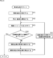
- FIG. 4 is a diagram illustrating a flow of a shooting process.
- FIG. 4 is a diagram illustrating a detailed example of a shooting condition. It is a figure showing an example of a photography range and a photography route.
- FIG. 3 is a diagram illustrating an example of a shooting location, a shooting interval, a shooting altitude, and a moving speed. It is a figure showing an example of an amount of overlap.
- FIG. 3 is a block diagram illustrating a configuration example of a moving object.
- FIG. 9 is a diagram illustrating an example in which a photographing altitude is corrected by analyzing a band of a photographed image.
- FIG. 9 is a flowchart illustrating a control process of FIG. 8.
- FIG. 4 is a diagram illustrating an example of a relationship between a band of a captured image and a shooting altitude.
- FIG. 7 is a diagram illustrating an example of correcting an overlap amount by analyzing a band of a captured image.
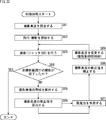
- FIG. 4 is a diagram schematically illustrating a range captured by a lens in a single shutter. It is a figure which shows typically the range taken in by the lens in the continuous several times of a shutter. It is a flowchart explaining the control process of FIG.
- FIG. 6 is a diagram illustrating an example of a relationship between a band of a captured image and an overlap amount.
- FIG. 4 is a diagram illustrating an example of a relationship between a band of a captured image and a shooting altitude.
- FIG. 7 is a diagram illustrating an example of correcting an overlap amount by analyzing a band of a captured image.
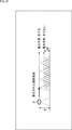
- FIG. 4 is a diagram schematic
- FIG. 9 is a diagram illustrating an example of correcting a moving speed by analyzing a blur amount of a captured image.
- 17 is a flowchart illustrating a control process of FIG. 16.
- FIG. 9 is a diagram illustrating an example of a relationship between an image blur amount and a moving speed.
- FIG. 9 is a diagram illustrating an example in which a photographing route is corrected by determining the success or failure of photographing of a photographed image.
- 20 is a flowchart illustrating a control process in FIG. 19.
- FIG. 11 is a diagram illustrating an example in which a photographing altitude or a moving speed is corrected by analyzing remaining power of a moving object.
- 22 is a flowchart illustrating a control process of FIG. 21.
- FIG. 21 is a flowchart illustrating a control process of FIG. 21.
- FIG. 6 is a diagram illustrating a relationship between a band of a captured image and a shooting altitude.
- FIG. 9 is a diagram illustrating a relationship between a predicted remaining power amount and a correction amount when photographing is completed.
- FIG. 21 is a block diagram illustrating another example of a mobile object control system to which the present technology is applied.
- FIG. 9 is a diagram illustrating an example of correcting a shooting range by analyzing power of two moving objects.
- 27 is a flowchart illustrating a control process of FIG. 26. It is a figure which shows the relationship of the residual electric power prediction amount at the time of imaging completion of two moving bodies.
- FIG. 11 is a diagram illustrating a configuration example of a computer.
- FIG. 1 is a diagram illustrating a moving object control system to which the present technology is applied.
- the moving object control system 1 includes a moving object 11 having an imaging unit 21 such as a camera.
- the mobile object 11 shown in FIG. 1 is a so-called drone which is an aircraft capable of unmanned flight.
- a mobile body that can move autonomously, such as a robot, a car, or a trolley, may be used as the mobile body 11.
- ⁇ When photographing a certain area using the moving body 11, it is necessary to determine a photographing plan in advance.
- a user specifies a desired shooting resolution and a shooting area, so that shooting conditions such as a route and a shooting location are set.
- the moving body 11 controls the photographing unit 21 to photograph the subject while moving based on the set photographing conditions.
- the moving body 11 corrects the preset photographing conditions based on the analysis result of the image photographed by the photographing unit 21. In the moving body 11, movement and shooting timing are controlled based on the corrected shooting conditions.
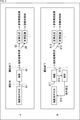
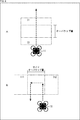
- FIG. 2 schematically shows a flow of a conventional moving object photographing process.
- a shooting condition is created before shooting, and then shooting is performed based on the created shooting condition as indicated by the tip of arrow # 1.
- the captured image is acquired by being taken in, for example, a PC as indicated by the arrow # 2, and a high-resolution image is generated by performing image synthesis as indicated by the arrow # 3.
- the control of the moving object is performed by performing the image recognition as indicated by the tip of arrow # 4.
- a moving object can only be photographed in accordance with a preset photographing condition. Therefore, for example, when it is not possible to take a picture according to the conditions due to disturbance such as a wind, an obstacle, or backlight, it is necessary to take a picture again or monitor a manned person.
- FIG. 2B schematically shows the flow of the photographing process in the mobile object control system 1 of FIG.
- a shooting condition is created before shooting, and then shooting is performed based on the created shooting condition, as indicated by the tip of arrow # 11.
- the captured image is acquired by being taken in, for example, a PC as shown by the arrow # 12, and a high-resolution image is generated by performing image synthesis as shown by the arrow # 13. You. Further, by performing the image recognition as shown at the tip of arrow # 14, the control of the moving body is performed.
- the flow of the photographing process shown in FIG. 2A is the same, but in the moving object control system 1, as shown at the end of arrow # 15, the analysis of the photographed image is completed before the photographing is completed. Done. Further, based on the analysis result, the photographing condition is corrected as indicated by the tip of arrow # 16. After the correction of the shooting conditions, shooting is performed based on the corrected shooting conditions.
- the mobile control system 1 it is possible to perform shooting under shooting conditions according to the situation at the time of shooting without re-taking the image.
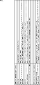
- FIG. 3 is a diagram illustrating an example of the photographing conditions.
- the shooting conditions include six shooting conditions for the moving object and two shooting conditions for the camera.
- the shooting conditions for the moving object include, for example, shooting altitude, shooting range, shooting route, shooting location, shooting speed, and overlap amount (side overlap amount).
- the shooting altitude is the shooting (flight) height from the ground (standard surface).
- the shooting range is the shooting target range (area).
- the shooting route is the flight order.
- the shooting route is usually set so as to cover the shooting range with one stroke.
- the photographing location is a position where the moving object is present while the shutter for photographing is opened and closed.
- the moving speed at the time of shooting is the moving speed or flying speed of the moving object at the time of shooting. If the moving speed during shooting is high, the shooting result may be blurred.
- the moving speed at the time of shooting is hereinafter referred to as a moving speed.
- the overlap amount is the amount of the overlapping range of the images to be synthesized when the moving body goes straight.
- the side overlap amount is the amount of the overlapping range of the images to be synthesized when the moving body bends.
- the amount of overlap and the amount of side overlap are represented by the ratio of how much overlap with the shooting range of one shutter.
- the photographing conditions for the camera include, for example, a photographed image storage resolution and a photographing exposure time.
- the captured image storage resolution is the number of pixels per unit area when a captured image is stored. The higher the captured image storage resolution, the more detailed objects can be described.
- the photographing exposure time is the shutter opening / closing time of one photographing. If the shooting exposure time is long, you can shoot brightly, but it is easy to shake.
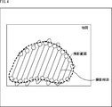
- FIG. 4 is a diagram showing an example of a shooting range and a shooting route as shooting conditions.
- FIG. 4 shows a map or aerial photograph of an area.
- the shooting range as the shooting condition in FIG. 3 is represented by a range surrounded by a broken line.
- the photographing path as the photographing condition in FIG. 3 is represented by a solid line connecting the photographing range and the vicinity of the edge with a single stroke.
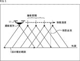
- FIG. 5 is a diagram illustrating an example of a shooting location, a shooting interval, a shooting altitude, and a moving speed as shooting conditions.
- FIG. 5 shows a state where the moving body 11 is photographing the ground.
- the shooting range of one shutter is represented by the base of the triangle.
- the shooting location under the shooting conditions in FIG. 3 is represented by a black circle at the vertex of the triangle.
- the shooting interval is represented between black circles.
- the shooting altitude under the shooting conditions in FIG. 3 is represented by an arrow from the moving body 11 to the ground.
- the moving speed under the photographing conditions in FIG. 3 is represented by an arrow pointing right from the moving body 11.
- FIG. 6 is a diagram showing an example of the amount of overlap.
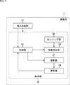
- FIG. 7 is a block diagram illustrating a configuration example of a moving object.
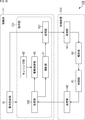
- the moving body 11 is composed of a power supply unit 51 and an operation unit 52.
- the power supply unit 51 includes a battery and a circuit for supplying power.
- the power supply unit 51 supplies power to the operation unit 52.
- the power supply unit 51 outputs information such as remaining power information to the operation unit 52.
- the remaining power information indicates the remaining power of the battery at the timing when the measurement is performed.
- the operation unit 52 includes a control unit 61, a sensing unit 62, a drive control unit 63, and an analysis unit 64 in addition to the above-described imaging unit 21. Each unit of the operation unit 52 operates with the power supplied from the power supply unit 51.
- the photographing unit 21 performs photographing based on the photographing instruction supplied from the control unit 61.
- the photographing unit 21 outputs a photographed image obtained by photographing to the analyzing unit 64.
- the control unit 61 is configured by a CPU, a ROM, a RAM, and the like, and controls the entire operation of the moving body 11 by executing a predetermined program.
- the control unit 61 creates shooting conditions for the mobile object 11 based on the input from the user and stores the shooting conditions in an internal memory.
- the control unit 61 corrects a preset photographing condition based on the analysis result of the image photographed by the photographing unit 21.
- control unit 61 calculates a correction value of the shooting condition for correcting the shooting condition based on the analysis result supplied from the analysis unit 64.
- the control unit 61 corrects the shooting conditions based on the calculated correction values, and outputs the corrected shooting conditions to the drive control unit 63.
- a method for example, among the photographing conditions, the photographing altitude, the photographing speed, the overlap amount, the photographing route, and the photographing range are corrected.
- the control unit 61 calculates a predicted remaining power amount at the end of all shooting. The control unit 61 corrects the shooting condition based on the calculated remaining power estimation amount.
- the sensing unit 62 includes various sensors for detecting altitude, attitude, speed, and the like.
- the sensing unit 62 outputs, to the drive control unit 63, sensing information indicating detection results such as altitude, attitude, and speed.
- the drive control unit 63 controls the driving of the moving body 11 based on the corrected photographing conditions. For example, the drive control unit 63 drives a motor or the like based on shooting conditions to move the moving body 11 to a desired position. When the moving body 11 is not operating according to the imaging conditions, the drive control unit 63 corrects the drive of the motor or the like using the sensing information supplied from the sensing unit 62.
- the analysis unit 64 analyzes the captured image supplied from the imaging unit 21 and outputs an analysis result such as a feature amount to the control unit 61.
- the analysis is performed in real time.
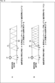
- FIG. 8 is a diagram illustrating an example in which the photographing altitude is corrected by analyzing the band of the photographed image.
- the analysis of the band of the captured image is performed by analyzing, for example, which frequency component is large as the spatial frequency of the captured image.
- a photographed image having a low band means that the image has a low frequency component and a gentle image
- a photographed image having a high band means that the image has a high frequency component and a fine image.
- the mobile unit 11 is corrected to increase the shooting altitude to the shooting altitude H1 (> H).
- the photographed image becomes an image having a lower resolution that cannot express fineness than the image at the photographing height H.
- the photographing range W1 > W
- the space P1 between the photographed places is also widened. Further, the number of photographing shutters is reduced, and the time required for photographing is reduced.
- the mobile body 11 is corrected to lower the shooting altitude to the shooting altitude H2 ( ⁇ H). .
- the shot image is an image having higher resolution that can be expressed more finely than the image at the shooting height H.
- the photographing range W2 ( ⁇ W) that can be photographed at one time becomes narrow. Further, the number of shooting shutters increases, and the time required for shooting increases.
- control for lowering the altitude may be performed in order to perform fine shooting.
- step S11 the control unit 61 sets the shooting altitude.
- step S12 the drive control section 63 starts flying / photographing.
- step S13 the photographing unit 21 performs one photographing with the shutter.
- the photographing unit 21 outputs a photographed image obtained by photographing to the analyzing unit 64.
- step S14 the control unit 61 determines whether or not shooting in the entire shooting range has been completed. If it is determined in step S14 that shooting in the entire shooting range has not been completed, the process proceeds to step S15.
- step S15 the analysis unit 64 analyzes the band of the captured image.
- the analysis unit 64 outputs the analysis result of the band of the captured image to the control unit 61.
- step S16 the control unit 61 calculates a correction value for correcting the photographing altitude based on the analysis result.
- the correction value of the photographing altitude is calculated using a graph as shown in FIG.
- FIG. 10 shows the relationship between the band of the photographed image and the photographing altitude. As shown in FIG. 10, as the band of the photographed image becomes higher, the photographing altitude becomes lower. For example, information indicating a relationship as shown in FIG. 10 preset by the user is stored in the memory of the control unit 61.
- the control unit 61 corrects the photographing altitude based on the correction value according to the analysis result of the band of the photographed image, and outputs the corrected photographing altitude to the drive control unit 63.
- step S17 the drive control unit 63 changes the shooting altitude based on the corrected shooting altitude supplied from the control unit 61.
- step S14 if it is determined in step S14 that the photographing in the entire photographing range has been completed, the control process ends.
- FIG. 11 is a diagram illustrating an example in which the overlap amount is corrected by analyzing the band of the captured image.
- the photographing by the moving body 11 is performed in one photographing range W, the overlap amount R, and the photographing interval P.
- the moving body 11 is modified to reduce the overlap amount R to the overlap amount R3 ( ⁇ R). You. In the case of FIG. 11A, the overlap amount R3 is almost zero.
- the captured image becomes an image having low resolution in which fineness cannot be expressed.
- the interval P3 between the imaging locations is also widened. Further, the number of photographing shutters is reduced, and the time required for photographing is reduced.
- the mobile unit 11 increases the overlap amount to the overlap amount R4 (> R). Will be modified.
- the shooting interval is controlled to be narrowed to the shooting interval P4 (> P).
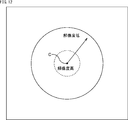
- FIG. 12 is a diagram schematically showing a range captured by the lens in one shutter.
- ⁇ Circle around (1) ⁇ in FIG. 12 indicates a range captured by the lens in one shutter, and a circle indicated by a broken line indicates a region near the center point C of the captured image.
- the shooting resolution is high in an area near the center point. As indicated by the dashed circle, in a region near the center point C of the captured image, the imaging resolution is high and decreases toward the end. It should be noted that the degree of reduction in the shooting resolution differs depending on the lens characteristics.
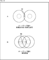
- FIG. 13 is a diagram schematically showing a range captured by the lens in a plurality of successive times of the shutter.
- FIG. 13 shows an overlap region of a range captured by the lens in a plurality of successive times of the shutter.
- the higher the overlap amount the higher the quality of the captured image can be obtained.
- step S21 the control unit 61 sets the amount of overlap.
- step S22 the drive control section 63 starts flying / photographing.
- step S23 the photographing unit 21 performs one photographing with the shutter.
- the photographing unit 21 outputs a photographed image obtained by photographing to the analyzing unit 64.
- step S24 the control unit 61 determines whether or not shooting in the entire shooting range has been completed. If it is determined in step S24 that shooting in the entire shooting range has not been completed, the process proceeds to step S25.
- step S25 the analysis unit 64 analyzes the band of the captured image.
- the analysis unit 64 outputs the analysis result of the band of the captured image to the control unit 61.
- step S26 the control unit 61 calculates a correction value for correcting the overlap amount based on the analysis result.
- the correction value of the overlap amount is calculated using a graph as shown in FIG.
- FIG. 15 shows the relationship between the band of the captured image and the amount of overlap. As shown in FIG. 15, as the band of the captured image becomes higher, the amount of overlap increases. For example, information indicating a relationship as shown in FIG. 15 preset by the user is stored in the memory of the control unit 61.
- the control unit 61 corrects the overlap amount based on the correction value according to the analysis result of the band of the captured image, and outputs the corrected overlap amount to the drive control unit 63.
- step S27 the drive control unit 63 changes the overlap amount based on the corrected overlap amount supplied from the control unit 61.
- step S24 if it is determined in step S24 that shooting in the entire shooting range has been completed, the control process ends.
- FIG. 16 is a diagram illustrating an example of correcting a moving speed by analyzing a blur amount of a captured image.
- Conditions that are likely to cause blurring in the captured image include when the brightness is low, when the wind is strong during flight, and when the aperture of the camera that constitutes the imaging unit is reduced (the depth of the subject is increased).
- the moving speed of the moving body 11 is set to the moving speed V1 ( ⁇ V). Modified to lower.
- the moving body 11 when the blur amount of the captured image by the moving body 11 that is shooting at the moving speed V is smaller than a predetermined threshold and the analysis result indicates that there is no blur, the moving body 11 Is modified to increase the moving speed to the moving speed V2 (> V).
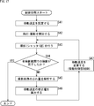
- step S41 the control unit 61 sets a shooting speed.
- step S42 the drive control section 63 starts flying and photographing.
- step S43 the photographing section 21 performs one shutter photographing.
- the photographing unit 21 outputs a photographed image obtained by photographing to the analyzing unit 64.
- step S44 the control unit 61 determines whether or not shooting in the entire shooting range has been completed. If it is determined in step S44 that shooting in the entire shooting range has not been completed, the process proceeds to step S45.
- step S45 the analysis unit 64 analyzes the blur amount of the captured image by comparing it with a predetermined threshold.
- the analysis unit 64 outputs an analysis result of the blur amount of the captured image to the control unit 61.
- step S46 the control unit 61 calculates a correction value for correcting the shooting speed based on the analysis result.
- the correction value of the shooting speed is calculated using a graph as shown in FIG.
- FIG. 18 shows the relationship between the image blur amount and the moving speed. As shown in FIG. 18, as the blur amount of the captured image increases, the moving speed decreases. For example, information indicating a relationship as shown in FIG. 18 preset by the user is stored in the memory of the control unit 61.
- the control unit 61 corrects the moving speed based on a correction value according to the analysis result of the blur amount of the captured image, and outputs the corrected moving speed to the drive control unit 63.
- step S47 the drive control unit 63 changes the moving speed based on the corrected moving speed supplied from the control unit 61.
- step S44 if it is determined in step S44 that shooting in the entire shooting range has been completed, the control process ends.
- FIG. 19 is a diagram illustrating an example in which the photographing route is corrected by determining the success or failure of the photographed image.
- the photographing image success / failure judgment of the photographed image for example, when the blur amount of the photographed image exceeds a predetermined threshold, the result of the judgment is a photographing failure. If the blur amount of the captured image does not exceed the predetermined threshold, the determination result is that the image capture has succeeded.
- the photographing route of the moving body 11 is corrected so as to return to the previous photographing place and photograph again. You. At this time, the shooting altitude does not change. It should be noted that the present invention is not limited to the immediately preceding shooting location, and may return to the two preceding shooting location.
- the photographing path is corrected, and control is performed so that the moving body 11 is returned to the previous photographing position and photographed again.
- the time required for shooting can be reduced as compared with the related art in which a portion where shooting failed after all shooting is completed is re-shot.
- step S61 the control section 61 sets a photographing route.
- step S62 the drive control section 63 starts flying / photographing.
- step S63 the photographing unit 21 performs photographing with one shutter.
- the photographing unit 21 outputs a photographed image obtained by photographing to the analyzing unit 64.
- step S64 the control unit 61 determines whether or not shooting in the entire shooting range has been completed. If it is determined in step S64 that shooting in the entire shooting range has not been completed, the process proceeds to step S65.
- step S65 the analysis unit 64 analyzes the captured image.
- the analysis unit 64 outputs the analysis result of the captured image to the control unit 61.
- step S66 the control unit 61 determines the success or failure of the photographed image based on the analysis result to determine whether the photographing was successful. If it is determined in step S66 that the shooting has been successful, the process returns to step S63, and the subsequent processing is repeated.
- step S66 If it is determined in step S66 that the shooting has failed, the process proceeds to step S67.
- the control unit 61 corrects the shooting path of the shooting condition with the correction value of the shooting path that has been corrected so as to include the path to the immediately preceding shooting location, and outputs the corrected shooting path to the drive control unit 63. .
- step S67 the drive control unit 63 changes the destination (imaging route) to the immediately preceding imaging location based on the corrected imaging route supplied from the control unit 61, and performs imaging.
- FIG. 21 is a diagram illustrating an example in which the photographing altitude or the moving speed is corrected by analyzing the remaining power of the moving object.
- the photographing altitude of the moving body 11 is calculated to have the same value so as to continue moving at the photographing altitude H.
- a correction value of the shooting altitude is calculated.
- the remaining power is predicted.
- control based on the calculated imaging altitude is performed.
- the photographing altitude or the correction value of the photographing altitude is corrected based on the remaining power. As a result, it is possible to use the remaining power efficiently and perform shooting until the end.
- steps S81 to S85 in FIG. 22 are the same as the processes in steps S11 to S15 in FIG. Duplicate descriptions will be omitted as appropriate.
- step S86 the control unit 61 calculates a correction value of the photographing altitude based on the analysis result of the band of the photographed image.
- the correction value of the shooting altitude is calculated using a graph as shown in FIG.
- FIG. 23 shows the relationship between the band of the photographed image and the photographing altitude.
- the band of the captured image is divided into three ranges: a low band, a middle band, and a high band.
- the photographing altitude becomes higher as the band becomes lower.
- the middle band range the shooting altitude is constant.
- the photographing altitude becomes lower as the band becomes higher.
- Information indicating a relationship as shown in FIG. 23 preset by the user is stored in the memory of the control unit 61.
- step S87 the control unit 61 predicts the remaining power.
- step S88 the control unit 61 corrects the correction value of the shooting altitude based on the estimated remaining power.
- the correction of the correction value of the photographing altitude is performed, for example, by multiplying the correction value by the correction amount.
- the correction amount is calculated using a graph as shown in FIG.
- FIG. 24 shows the relationship between the remaining power prediction amount and the correction amount at the time of completion of shooting.
- the correction amount is set to 1.0.
- the correction amount also approaches 0 according to the predicted remaining power.
- Information indicating the relationship as shown in FIG. 24 is stored in the memory of the control unit 61.
- the control unit 61 multiplies the correction value of the photographing altitude according to the analysis result of the band of the photographed image by the correction amount to correct the photographing altitude of the photographing condition, and outputs the corrected photographing altitude to the drive control unit 63.
- step S89 the drive control unit 63 changes the shooting altitude based on the corrected shooting altitude supplied from the control unit 61.
- step S84 if it is determined in step S84 that the shooting in the entire shooting range has been completed, the control processing ends.
- FIG. 25 is a block diagram illustrating another example of a moving object control system to which the present technology is applied.
- the moving object control system 101 includes a moving object 111 and a control device 112. Parts corresponding to those in FIG. 7 are denoted by the same reference numerals.
- the configuration of the mobile control system 101 in FIG. 25 differs from the configuration in FIG. 7 in that the control unit 61 and the analysis unit 64 are provided in the control device 112. That is, the control of the moving body is not performed autonomously by the moving body, but is performed by the control device 112 which is an external device.
- the mobile object 111 and the control device 112 are provided with a receiving unit and a transmitting unit, respectively. Between the mobile unit 111 and the control device 112, the photographing conditions are transmitted at any time by wireless communication or the like. Note that there may be some transmission intervals, but in that case, a delay may occur and control accuracy may decrease.
- the moving body 111 includes a drone, a robot, a car, a trolley, and the like having the photographing unit 21 as in the case of the moving body 11 in FIG.
- the moving body 111 includes the power supply unit 51 and the operation unit 121.
- the operation unit 121 includes a transmission unit 131 and a reception unit 132 in addition to the above-described imaging unit 21, sensing unit 62, and drive control unit 63. Each unit of the operation unit 121 operates with the power supplied from the power supply unit 51.
- the transmission unit 131 transmits the captured image supplied from the imaging unit 21 and information such as remaining power information supplied from the power supply unit 51 to the control device 112.
- the receiving unit 132 receives the photographing condition transmitted from the control device 112 and outputs the photographing condition to the drive control unit 63.
- the receiving unit 132 receives the photographing instruction transmitted from the control device 112 and outputs it to the photographing unit 21.
- the control device 112 is configured by a personal computer, a tablet terminal, a smartphone, or the like.
- the control device 112 includes the control unit 61, the analysis unit 64, the reception unit 141, and the transmission unit 142 in FIG.
- the receiving unit 141 receives the captured image and the remaining power information transmitted from the moving body 111 and outputs the information to the analyzing unit 64.
- the transmission unit 142 transmits the imaging instruction supplied from the control unit 61 and information such as the imaging conditions supplied from the control unit 61 to the mobile unit 111.
- the correction of the photographing conditions as described above is performed by the control device 112.
- FIG. 26 is a diagram illustrating an example in which the photographing range is corrected by analyzing the remaining power of two moving objects.
- the entire photographing range is photographed by the two moving bodies 111A and 111B.
- the moving body 111A and the moving body 111B have the same configuration as that of the moving body 111 in FIG. Under the photographing conditions before photographing, the size of the photographing range of the moving body 111A is substantially the same as the size of the photographing range of the moving body 111B.
- the control device 112 analyzes the captured images from the moving bodies 111A and 111B, and calculates the correction values of the photographing altitude and the photographing speed based on the analysis result of the photographed images. Further, the control device 112 predicts the remaining power at the time of the completion of the imaging based on the remaining power information from the moving bodies 111A and 111B.
- the control device 112 calculates a correction value of the shooting range in which a part of the shooting range of the moving body 111A is reduced, as indicated by a white arrow in FIG.
- the control device 112 corrects the shooting range of the shooting condition with the calculated correction value of the shooting range, and transmits the corrected shooting range to the moving body 111A.
- the control device 112 calculates a correction value of the imaging range obtained by increasing a part of the imaging range of the moving body 111B.
- the control device 112 corrects the shooting range of the shooting condition with the calculated correction value of the shooting range, and transmits the corrected shooting range to the moving body 111B.
- step S111 the control unit 61 sets the photographing range of the moving body 111A and the moving body 111B.
- step S112 the drive control section 63 starts flying / photographing.
- step S113 the photographing section 21 performs one-time photographing with the shutter.
- the photographing unit 21 outputs a photographed image obtained by photographing to the analyzing unit 64.
- step S114 the control unit 61 determines whether or not each of the mobile object 111A and the mobile object 111B has completed shooting in the shooting range in charge. If it is determined in step S114 that shooting in the assigned shooting range has not been completed, the process proceeds to step S115.
- step S115 the analysis unit 64 analyzes the captured image.
- the analysis unit 64 outputs the analysis result of the captured image to the control unit 61.
- step S116 the control unit 61 controls the mobile unit 111A and the mobile unit 111B based on the analysis result. For example, among the photographing conditions, the photographing altitude, the moving speed, the overlap amount, and the like are controlled as described above.
- step S117 the control unit 61 predicts the remaining power based on the remaining power information from the moving bodies 111A and 111B.
- step S118 the control unit 61 calculates a correction value of the shooting range based on the remaining power prediction amount that is information indicating the remaining power predicted by the moving bodies 111A and 111B.
- the correction value of the imaging range is calculated based on the increase or decrease of the allocation of the imaging range to each of the moving bodies 111A and 111B.
- FIG. 28 shows the relationship between the estimated remaining power of the mobile unit 111A at the time of completion of imaging and the estimated amount of remaining power of the mobile unit 111B at the completion of imaging.
- the control unit 61 corrects the imaging ranges of the imaging conditions of the mobile object 111A and the mobile object 111B with the correction values of the imaging range calculated based on the estimated remaining power.
- step S119 the control unit 61 causes the drive control unit 63 of the moving body 111A and the moving body 111B to change the photographing range by transmitting the corrected shooting range to the moving body 111A and the moving body 111B, respectively.
- FIG. 27 an example in which the control method of FIG. 26 is performed by the mobile control system 101 of FIG. 25 has been described, but the control method of FIG. 26 may be performed by the mobile control system 1 of FIG.
- control methods of FIGS. 8, 11, 16, 19, and 21 which describe the example performed by the mobile control system 1 of FIG. 1 are executed by the mobile control system 101 of FIG. It may be made to be performed.
- a preset imaging condition is corrected from an analysis result of an image captured by an imaging device provided on a moving object, and driving of the moving object is performed based on the corrected imaging condition. Controlled.
- Computer> ⁇ Computer hardware configuration example>
- the series of processes described above can be executed by hardware or can be executed by software.
- a program constituting the software is installed in a computer.
- the computer includes a computer incorporated in dedicated hardware, a general-purpose personal computer that can execute various functions by installing various programs, and the like.
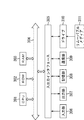
- FIG. 29 is a block diagram showing a configuration example of hardware of a computer that executes the above-described series of processing by a program.
- a CPU Central Processing UNIT
- ROM Read Only Memory
- RAM Random Access Memory
- the input / output interface 305 is further connected to the bus 304.
- the input unit 306, the output unit 307, the storage unit 308, the communication unit 309, and the drive 310 are connected to the input / output interface 305.
- the input unit 306 includes a keyboard, a mouse, a microphone, and the like.
- the output unit 307 includes a display, a speaker, and the like.
- the storage unit 308 includes a hard disk, a nonvolatile memory, and the like.
- the communication unit 309 includes a network interface and the like.
- the drive 310 drives a removable medium 311 such as a magnetic disk, an optical disk, a magneto-optical disk, or a semiconductor memory.
- the CPU 301 loads, for example, a program stored in the storage unit 308 into the RAM 303 via the input / output interface 305 and the bus 304 and executes the program. Is performed.
- the program executed by the computer (CPU 301) can be provided by being recorded on a removable medium 311 as a package medium or the like, for example. Further, the program can be provided via a wired or wireless transmission medium such as a local area network, the Internet, or digital satellite broadcasting.
- the program can be installed in the storage unit 308 via the input / output interface 305 by attaching the removable medium 311 to the drive 310. Further, the program can be received by the communication unit 309 via a wired or wireless transmission medium and installed in the storage unit 308. In addition, the program can be installed in the ROM 302 or the storage unit 308 in advance.
- the program executed by the computer may be a program in which processing is performed in chronological order according to the order described in this specification, or may be performed in parallel or at a necessary timing such as when a call is made. It may be a program that performs processing.
- a system refers to a set of a plurality of components (devices, modules (parts), and the like), and it does not matter whether all components are in the same housing. Therefore, a plurality of devices housed in separate housings and connected via a network, and one device housing a plurality of modules in one housing are all systems. .
- the present technology can adopt a configuration of cloud computing in which one function is shared by a plurality of devices via a network and processed jointly.
- each step described in the above-described flowchart can be executed by one device, or can be shared and executed by a plurality of devices.
- one step includes a plurality of processes
- the plurality of processes included in the one step may be executed by one device or may be shared and executed by a plurality of devices.
- the present technology can also have the following configurations.
- a control unit that corrects a preset photographing condition based on an analysis result of an image photographed by a photographing device provided in the moving body A drive control unit configured to control driving of the moving body based on the corrected imaging condition.
- the control device according to (1) further including: an analysis unit configured to analyze the image in real time.
- the control unit corrects the photographing condition based on an analysis result of a frequency component of the image, The control device according to (1) or (2), wherein the drive control unit changes a shooting altitude of the moving object based on the corrected shooting condition.
- the control unit corrects the photographing condition based on an analysis result of a frequency component of the image, The control device according to any one of (1) to (3), wherein the drive control unit changes a shooting interval of the moving object based on the corrected shooting condition.
- the control unit corrects the imaging condition based on the analysis result of the blur amount of the image, The control device according to (1) or (2), wherein the drive control unit changes the speed of the moving object based on the corrected imaging condition.
- the control unit corrects the imaging conditions based on an analysis result of analyzing whether the imaging of the image was successful or failed, The control device according to (1) or (2), wherein the drive control unit changes a shooting location of the moving body based on the corrected shooting conditions.
- the control unit based on the analysis result of the remaining power of the moving body, corrects the corrected imaging conditions, The control device according to any one of (1) to (6), wherein the drive control unit changes a shooting altitude or a speed of the moving object based on the corrected shooting conditions.
- the control unit corrects the imaging condition based on the analysis result of the remaining power of the plurality of moving objects, The control device according to (1) or (2), wherein the drive control unit changes a shooting range of the plurality of moving objects based on the corrected shooting condition.
- the control device is Correct the photographing conditions based on the analysis result of the image photographed by the photographing device provided on the moving body, A control method for controlling driving of the moving body based on the corrected photographing condition.
- a control unit that corrects a photographing condition based on an analysis result of an image photographed by a photographing device provided in the moving body A program that causes a computer to function as a drive control unit that controls driving of the moving object based on the corrected shooting conditions.
- 1 ⁇ mobile unit control system ⁇ 11 ⁇ mobile unit, ⁇ 51 ⁇ power supply unit, ⁇ 52 ⁇ operation unit, ⁇ 61 ⁇ control unit, ⁇ 62 ⁇ sensing unit, ⁇ 63 ⁇ drive control unit, ⁇ 64 ⁇ analysis unit, ⁇ 101 ⁇ mobile unit control system, ⁇ 111, 111A, 111B ⁇ mobile unit, 112 control device, ⁇ 121 ⁇ operation unit, ⁇ 131 ⁇ transmission unit, ⁇ 132 ⁇ reception unit, ⁇ 141 ⁇ reception unit, ⁇ 142 ⁇ transmission unit
Landscapes
- Engineering & Computer Science (AREA)
- Aviation & Aerospace Engineering (AREA)
- Remote Sensing (AREA)
- Physics & Mathematics (AREA)
- General Physics & Mathematics (AREA)
- Multimedia (AREA)
- Signal Processing (AREA)
- Automation & Control Theory (AREA)
- Radar, Positioning & Navigation (AREA)
- Mechanical Engineering (AREA)
- Studio Devices (AREA)
- Stereoscopic And Panoramic Photography (AREA)
Abstract
La présente technologie concerne un dispositif de contrôle, un procédé et un programme avec lesquels il est possible de capturer une image dans des conditions d'imagerie optimales. Dans la présente invention, une unité de commande corrige des conditions d'imagerie prédéfinies sur la base d'un résultat d'analyse d'une image capturée par un dispositif d'imagerie fourni à un corps mobile. Une unité de commande d'entraînement commande l'entraînement du corps mobile sur la base des conditions d'imagerie corrigées. La présente technologie peut être appliquée à un système de commande de corps mobile qui commande un corps mobile.
Priority Applications (4)
| Application Number | Priority Date | Filing Date | Title |
|---|---|---|---|
| CN201980041166.9A CN112335226A (zh) | 2018-06-26 | 2019-06-12 | 控制装置、方法以及程序 |
| JP2020527376A JP7310811B2 (ja) | 2018-06-26 | 2019-06-12 | 制御装置および方法、並びにプログラム |
| US17/252,888 US12010426B2 (en) | 2018-06-26 | 2019-06-12 | Control device and method |
| US18/673,722 US12556819B2 (en) | 2018-06-26 | 2024-05-24 | Control device and method |
Applications Claiming Priority (2)
| Application Number | Priority Date | Filing Date | Title |
|---|---|---|---|
| JP2018120458 | 2018-06-26 | ||
| JP2018-120458 | 2018-06-26 |
Related Child Applications (2)
| Application Number | Title | Priority Date | Filing Date |
|---|---|---|---|
| US17/252,888 A-371-Of-International US12010426B2 (en) | 2018-06-26 | 2019-06-12 | Control device and method |
| US18/673,722 Continuation US12556819B2 (en) | 2018-06-26 | 2024-05-24 | Control device and method |
Publications (1)
| Publication Number | Publication Date |
|---|---|
| WO2020004029A1 true WO2020004029A1 (fr) | 2020-01-02 |
Family
ID=68987077
Family Applications (1)
| Application Number | Title | Priority Date | Filing Date |
|---|---|---|---|
| PCT/JP2019/023232 Ceased WO2020004029A1 (fr) | 2018-06-26 | 2019-06-12 | Dispositif de commande, procédé, et programme |
Country Status (4)
| Country | Link |
|---|---|
| US (2) | US12010426B2 (fr) |
| JP (1) | JP7310811B2 (fr) |
| CN (1) | CN112335226A (fr) |
| WO (1) | WO2020004029A1 (fr) |
Cited By (4)
| Publication number | Priority date | Publication date | Assignee | Title |
|---|---|---|---|---|
| WO2021014699A1 (fr) * | 2019-07-19 | 2021-01-28 | 株式会社Nttドコモ | Dispositif de traitement d'informations |
| WO2021255940A1 (fr) * | 2020-06-19 | 2021-12-23 | 株式会社ナイルワークス | Drone pour diagnostiquer une croissance de récolte, et système de caméra pour celui-ci |
| JP2023072353A (ja) * | 2021-11-12 | 2023-05-24 | 株式会社Soken | 移動体の移動経路決定装置、移動体の移動経路決定方法及び移動体の移動経路決定プログラム |
| WO2023233997A1 (fr) * | 2022-05-31 | 2023-12-07 | ソニーグループ株式会社 | Procédé d'instruction d'imagerie, objet mobile et programme |
Citations (3)
| Publication number | Priority date | Publication date | Assignee | Title |
|---|---|---|---|---|
| JP2006145357A (ja) * | 2004-11-18 | 2006-06-08 | Pasuko:Kk | 撮影計画支援装置及びそのためのプログラム |
| JP2017007603A (ja) * | 2015-06-25 | 2017-01-12 | 三菱自動車工業株式会社 | 運転支援制御装置 |
| JP2018152737A (ja) * | 2017-03-13 | 2018-09-27 | ヤンマー株式会社 | 無人飛行撮影装置 |
Family Cites Families (20)
| Publication number | Priority date | Publication date | Assignee | Title |
|---|---|---|---|---|
| KR101842031B1 (ko) * | 2013-12-11 | 2018-03-26 | 한화테크윈 주식회사 | 감시 시스템 |
| US9688403B2 (en) * | 2014-05-20 | 2017-06-27 | Infatics, Inc. | Method for adaptive mission execution on an unmanned aerial vehicle |
| US10788235B2 (en) * | 2014-11-07 | 2020-09-29 | Sony Corporation | Control system, control method, and storage medium |
| GB201506329D0 (en) * | 2015-04-14 | 2015-05-27 | Vito Nv | System and method for processing images of a ground surface |
| EP3101889A3 (fr) * | 2015-06-02 | 2017-03-08 | LG Electronics Inc. | Terminal mobile et son procédé de contrôle |
| FR3038482B1 (fr) | 2015-06-30 | 2017-08-11 | Parrot | Bloc camera apte a etre embarque dans un drone pour cartographier un terrain et procede de gestion de capture d'images par un bloc camera |
| JP6557534B2 (ja) | 2015-07-22 | 2019-08-07 | 鹿島建設株式会社 | 監視装置 |
| KR102364730B1 (ko) * | 2015-07-29 | 2022-02-18 | 엘지전자 주식회사 | 이동 단말기 및 이의 제어방법 |
| CN106476562A (zh) | 2015-08-31 | 2017-03-08 | 株式会社电装 | 车辆用空调装置以及车辆用空调控制装置 |
| US10008123B2 (en) * | 2015-10-20 | 2018-06-26 | Skycatch, Inc. | Generating a mission plan for capturing aerial images with an unmanned aerial vehicle |
| JP6727791B2 (ja) * | 2015-11-05 | 2020-07-22 | キヤノン株式会社 | 追尾制御装置および追尾制御方法、撮像装置 |
| US10086309B2 (en) * | 2015-11-25 | 2018-10-02 | Casio Computer Co., Ltd. | Flight device, flight method thrown by user and storage medium |
| KR20170136750A (ko) * | 2016-06-02 | 2017-12-12 | 삼성전자주식회사 | 전자 장치 및 그의 동작 방법 |
| US9984672B2 (en) * | 2016-09-15 | 2018-05-29 | Gopro, Inc. | Noise cancellation for aerial vehicle |
| KR20180051996A (ko) * | 2016-11-09 | 2018-05-17 | 삼성전자주식회사 | 무인 비행 장치 및 이를 이용한 피사체 촬영 방법 |
| US11184524B2 (en) * | 2016-11-25 | 2021-11-23 | Sony Group Corporation | Focus control device, focus control method, program, and imaging device |
| KR20180064148A (ko) * | 2016-12-05 | 2018-06-14 | 삼성전자주식회사 | 전자 장치 및 전자 장치 제어 방법 |
| CN107589691A (zh) | 2017-08-11 | 2018-01-16 | 北京小米移动软件有限公司 | 无人机的拍摄控制方法及装置 |
| WO2019148088A1 (fr) * | 2018-01-29 | 2019-08-01 | Aerovironment, Inc. | Procédés et systèmes de décollage et d'atterrissage écoénergétiques pour véhicules aériens à décollage et atterrissage verticaux (vtol) |
| US11592838B2 (en) * | 2018-02-28 | 2023-02-28 | Instrumems Inc. | Velocity sensing for aircraft |
-
2019
- 2019-06-12 US US17/252,888 patent/US12010426B2/en active Active
- 2019-06-12 JP JP2020527376A patent/JP7310811B2/ja active Active
- 2019-06-12 WO PCT/JP2019/023232 patent/WO2020004029A1/fr not_active Ceased
- 2019-06-12 CN CN201980041166.9A patent/CN112335226A/zh active Pending
-
2024
- 2024-05-24 US US18/673,722 patent/US12556819B2/en active Active
Patent Citations (3)
| Publication number | Priority date | Publication date | Assignee | Title |
|---|---|---|---|---|
| JP2006145357A (ja) * | 2004-11-18 | 2006-06-08 | Pasuko:Kk | 撮影計画支援装置及びそのためのプログラム |
| JP2017007603A (ja) * | 2015-06-25 | 2017-01-12 | 三菱自動車工業株式会社 | 運転支援制御装置 |
| JP2018152737A (ja) * | 2017-03-13 | 2018-09-27 | ヤンマー株式会社 | 無人飛行撮影装置 |
Cited By (7)
| Publication number | Priority date | Publication date | Assignee | Title |
|---|---|---|---|---|
| WO2021014699A1 (fr) * | 2019-07-19 | 2021-01-28 | 株式会社Nttドコモ | Dispositif de traitement d'informations |
| JPWO2021014699A1 (fr) * | 2019-07-19 | 2021-01-28 | ||
| JP7208402B2 (ja) | 2019-07-19 | 2023-01-18 | 株式会社Nttドコモ | 情報処理装置 |
| WO2021255940A1 (fr) * | 2020-06-19 | 2021-12-23 | 株式会社ナイルワークス | Drone pour diagnostiquer une croissance de récolte, et système de caméra pour celui-ci |
| JPWO2021255940A1 (fr) * | 2020-06-19 | 2021-12-23 | ||
| JP2023072353A (ja) * | 2021-11-12 | 2023-05-24 | 株式会社Soken | 移動体の移動経路決定装置、移動体の移動経路決定方法及び移動体の移動経路決定プログラム |
| WO2023233997A1 (fr) * | 2022-05-31 | 2023-12-07 | ソニーグループ株式会社 | Procédé d'instruction d'imagerie, objet mobile et programme |
Also Published As
| Publication number | Publication date |
|---|---|
| US12556819B2 (en) | 2026-02-17 |
| JPWO2020004029A1 (ja) | 2021-08-05 |
| US20210266464A1 (en) | 2021-08-26 |
| US12010426B2 (en) | 2024-06-11 |
| US20240314436A1 (en) | 2024-09-19 |
| CN112335226A (zh) | 2021-02-05 |
| JP7310811B2 (ja) | 2023-07-19 |
Similar Documents
| Publication | Publication Date | Title |
|---|---|---|
| US11003893B2 (en) | Face location tracking method, apparatus, and electronic device | |
| US12556819B2 (en) | Control device and method | |
| EP3627821B1 (fr) | Procédé et appareil de mise au point permettant d'obtenir un visage humain net, et dispositif informatique | |
| US20180316864A1 (en) | Scene Motion Correction In Fused Image Systems | |
| US20180278820A1 (en) | Optical detection apparatus and methods | |
| US11388340B2 (en) | Image processing device, image processing method, and image processing system for image stabilization | |
| US20190230269A1 (en) | Monitoring camera, method of controlling monitoring camera, and non-transitory computer-readable storage medium | |
| US9648238B2 (en) | Image processing device that synthesizes a plurality of images, method of controlling the same, storage medium, and image pickup apparatus | |
| CN110383335A (zh) | 视频内容中基于光流和传感器输入的背景减除 | |
| US10951821B2 (en) | Imaging control device, imaging system, and imaging control method | |
| CN102318334A (zh) | 图像处理装置、摄像装置以及图像处理方法 | |
| CN109949381B (zh) | 图像处理方法、装置、图像处理芯片、摄像组件及飞行器 | |
| CN115152200A (zh) | 摄像头的帧率调节方法、装置、电子设备及存储介质 | |
| US20200154023A1 (en) | Location estimation device, location estimation method, and program recording medium | |
| CN104243796A (zh) | 摄影装置、摄影方法、模板创建装置和模板创建方法 | |
| US12162368B2 (en) | Computerized system and method for dynamic camera and scene adjustment for autonomous charging | |
| CN113661513A (zh) | 一种图像处理方法、设备、图像处理系统及存储介质 | |
| US20160156826A1 (en) | Image-capturing device and image-capturing method | |
| KR101783990B1 (ko) | 디지털 영상 처리 장치 및 영상의 대표 움직임 예측 방법 | |
| CN114608555B (zh) | 目标定位方法、系统及存储介质 | |
| CN108074247A (zh) | 视频帧产生方法及其系统 | |
| CN115047890A (zh) | 无人船控制方法、设备及计算机可读存储介质 | |
| WO2018219274A1 (fr) | Procédé et appareil de traitement de débruitage, support d'informations et terminal | |
| US9911061B2 (en) | Fast histogram-based object tracking | |
| CN110401793A (zh) | 用于控制智能终端的方法和装置 |
Legal Events
| Date | Code | Title | Description |
|---|---|---|---|
| 121 | Ep: the epo has been informed by wipo that ep was designated in this application |
Ref document number: 19825843 Country of ref document: EP Kind code of ref document: A1 |
|
| WWE | Wipo information: entry into national phase |
Ref document number: 2020527376 Country of ref document: JP |
|
| NENP | Non-entry into the national phase |
Ref country code: DE |
|
| 122 | Ep: pct application non-entry in european phase |
Ref document number: 19825843 Country of ref document: EP Kind code of ref document: A1 |