WO2020004160A1 - Dispositif de transport pour corps de sac lié - Google Patents
Dispositif de transport pour corps de sac lié Download PDFInfo
- Publication number
- WO2020004160A1 WO2020004160A1 PCT/JP2019/024189 JP2019024189W WO2020004160A1 WO 2020004160 A1 WO2020004160 A1 WO 2020004160A1 JP 2019024189 W JP2019024189 W JP 2019024189W WO 2020004160 A1 WO2020004160 A1 WO 2020004160A1
- Authority
- WO
- WIPO (PCT)
- Prior art keywords
- bag
- transfer
- pair
- bag body
- connecting bag
- Prior art date
- Legal status (The legal status is an assumption and is not a legal conclusion. Google has not performed a legal analysis and makes no representation as to the accuracy of the status listed.)
- Ceased
Links
Images



Classifications
-
- B—PERFORMING OPERATIONS; TRANSPORTING
- B65—CONVEYING; PACKING; STORING; HANDLING THIN OR FILAMENTARY MATERIAL
- B65B—MACHINES, APPARATUS OR DEVICES FOR, OR METHODS OF, PACKAGING ARTICLES OR MATERIALS; UNPACKING
- B65B59/00—Arrangements to enable machines to handle articles of different sizes, to produce packages of different sizes, to vary the contents of packages, to handle different types of packaging material, or to give access for cleaning or maintenance purposes
- B65B59/001—Arrangements to enable adjustments related to the product to be packaged
-
- B—PERFORMING OPERATIONS; TRANSPORTING
- B65—CONVEYING; PACKING; STORING; HANDLING THIN OR FILAMENTARY MATERIAL
- B65B—MACHINES, APPARATUS OR DEVICES FOR, OR METHODS OF, PACKAGING ARTICLES OR MATERIALS; UNPACKING
- B65B61/00—Auxiliary devices, not otherwise provided for, for operating on sheets, blanks, webs, binding material, containers or packages
- B65B61/04—Auxiliary devices, not otherwise provided for, for operating on sheets, blanks, webs, binding material, containers or packages for severing webs, or for separating joined packages
- B65B61/06—Auxiliary devices, not otherwise provided for, for operating on sheets, blanks, webs, binding material, containers or packages for severing webs, or for separating joined packages by cutting
-
- B—PERFORMING OPERATIONS; TRANSPORTING
- B65—CONVEYING; PACKING; STORING; HANDLING THIN OR FILAMENTARY MATERIAL
- B65G—TRANSPORT OR STORAGE DEVICES, e.g. CONVEYORS FOR LOADING OR TIPPING, SHOP CONVEYOR SYSTEMS OR PNEUMATIC TUBE CONVEYORS
- B65G13/00—Roller-ways
-
- B—PERFORMING OPERATIONS; TRANSPORTING
- B65—CONVEYING; PACKING; STORING; HANDLING THIN OR FILAMENTARY MATERIAL
- B65G—TRANSPORT OR STORAGE DEVICES, e.g. CONVEYORS FOR LOADING OR TIPPING, SHOP CONVEYOR SYSTEMS OR PNEUMATIC TUBE CONVEYORS
- B65G2201/00—Indexing codes relating to handling devices, e.g. conveyors, characterised by the type of product or load being conveyed or handled
- B65G2201/02—Articles
- B65G2201/0235—Containers
- B65G2201/0238—Bags
Definitions
- the present invention is a connection for storing soups such as udon, buckwheat, ramen, sauces, sauces, liquids such as dressings, shampoos, drenches, powdered soups, spices, oysters, desiccants, deoxidizing materials, medicines, etc.
- the present invention relates to an apparatus for transferring a connected bag for cutting the bag into individual containers and putting the bag into a container or the like.
- Patent Literature 1 a connecting bag body connected with individual bags via a connecting piece is transferred by a transfer mechanism, and the connecting piece is cut by a cutting mechanism at a transfer destination and cut into individual packing bags.
- a transfer device that puts individual packaging bags into containers or packaging bags one by one is used.
- the transfer mechanism of the transfer device presses and holds both sides of the connecting bag with a pair of parallel belt conveyors, and transfers the connecting bag to the cutting mechanism by rotating the belt conveyor.
- the present invention is intended to solve the above-described problem, and there is a possibility that these foreign substances are erroneously mixed into a container or the like into which an individual bag is inserted, without generating foreign substances from members constituting the transfer device. It is an object of the present invention to obtain a transfer device for a connection bag without a connection bag.
- the present invention includes an individual bag in which the contents are housed and formed of a film member, and the sealing portion of the film member is formed in a band along one or both sides.
- the seal portion is a transfer device for connecting a plurality of connecting bags via a connecting piece formed in a vertical direction, and a transfer mechanism for transferring the connecting bags in a horizontal direction, and a transfer mechanism for transferring the connecting bags.
- a cutting mechanism that cuts the connecting piece of the connecting bag, and disposed at an interval between the transfer mechanism and the cutting mechanism, and by pressing and holding the seal portion of the connecting bag in the vertical direction and rotating in the transfer direction, And a pair of upper and lower rotating members capable of transferring the connection bag in the transfer direction, wherein the transfer mechanism includes a roller for mounting the connection bag, which is rotatably disposed in a direction perpendicular to the transfer direction. Part and the roller It is obtained by a pair of guide members which are arranged along the both sides of the coupling receptacle.
- the pair of guide bodies are assembled so as to be slidable in a direction perpendicular to the transfer direction, and the distance between the guide bodies can be adjusted according to the width direction length of the connecting bag body. It may be.
- the pair of guides has a flange protruding along the upper surface on one side opposed to each other, and a transfer interval of a connection bag formed by the flange and one side of the pair of guides. Therefore, the connecting bag located within the transfer interval may be prevented from protruding outward.
- the present invention provides a roller for placing a connecting bag, a pair of guides provided on both sides of the roller, and a connecting bag by pressing and holding a seal of the connecting bag.
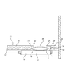
- FIG. 1 is a partially enlarged cross-sectional view illustrating a first embodiment of the present invention.
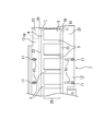
- FIG. 3 is a partially enlarged plan view showing a connecting bag body arranged in a transfer mechanism.
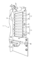
- FIG. 2 is a perspective view illustrating a roller unit according to the first embodiment.
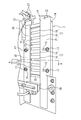
- FIG. 2 is a perspective view illustrating a transfer mechanism according to the first embodiment. The perspective view which shows a pair of rotating bodies.
- FIG. 5 is an end view taken along line AA of FIG. 4.
- FIG. 2 is a partially enlarged sectional view of FIG. 1.
- (1) is a connecting bag body of an individual bag (2), and an individual bag formed of a film member (3).
- the inside of (2) contains contents such as sauces and sauces, and a band-shaped seal portion (4) is provided on one side as shown in FIG.
- a connecting piece (5) for connecting adjacent individual packaging (2) is provided in a direction perpendicular to the seal portion (4).
- the seal portion (4) is provided on one side of the individual bag (2) in the present embodiment, the present invention is not limited to this in other different embodiments, and the seal portions (4) are provided on both sides of the individual bag (2). It is also possible to use those provided with 4).
- the transfer device (6) of the present embodiment includes a transfer mechanism (7) for transferring the connection bag (1), and a connection bag transferred from the transfer mechanism (7). And a cutting mechanism (8) for cutting the connecting piece (5) of (1) into an individual bag (2).
- the transfer mechanism (7) includes a roller portion (11) provided with a plurality of stainless steel rollers (10) as shown in FIG. 3 and an upper portion on both sides of the roller portion (11) as shown in FIG.
- the roller (10) is formed by assembling a pair of guide bodies (12) and (13) which are elongated in the vertical direction.
- the roller portion (11) includes a plurality of rollers (10) arranged in a long rectangular frame (14) in parallel with the width direction of the frame (14). 10) are assembled via bearings (not shown) so as to be individually rotatable. Above the roller portion (11), a pair of long plate-like guide bodies (12) and (13) are respectively placed at positions corresponding to both ends of the roller portion (11) as shown in FIG. It is fixedly arranged on the frame (14).
- a pair of long holes (15) are formed in the pair of guide bodies (12) and (13), respectively, in a direction perpendicular to the length direction of the guide bodies (12) and (13).
- a screw hole (16) is formed in the frame (14) of the roller portion (11) at a position corresponding to the elongated hole (15).
- the screw member (17) is screwed and fixed as shown in FIG.
- a pair of guide bodies (12) and (13) are fixedly arranged in the length direction of the frame body (14).
- the pair of guide bodies (12) and (13) are connected and fixed to the roller portion (11) through the elongated holes (15).
- the arrangement interval between the pair of guide bodies (12) and (13) can be appropriately changed depending on the screwing position. Therefore, within the range of the formation length of the elongated hole (15), the pair of guide bodies (12) and (13) can be assembled by widening or narrowing the gap.
- the pair of guides (12) and (13) are horizontally moved in the vertical direction with respect to the transfer direction of the connecting bag body (1) according to the width of the connecting bag body (1) to be transferred.
- the connecting bag body (1) can be assembled and fixed to the roller portion (11) while being adjusted so that the connecting bag body (1) can be arranged within the interval between the pair of guide bodies (12) and (13). Therefore, as shown in FIG. 5, a pair of guides (12) and (13) can be arranged along both sides (18) of the connecting bag (1) placed on the roller (11).
- the pair of guides (12) and (13) have upper surfaces (21) on one side (19) and (20) along one side (19) and (20) facing each other. Flanges (23) and (24) protrude from the (22) side. By providing the flanges (23) and (24) on the pair of guides (12) and (13), the flanges (23) and (24) of the pair of guides (12) and (13) are combined. From the transfer interval (25) of the connecting bag (1) formed by the sides (19) and (20), it is necessary to prevent the connecting bag (1) located within the transfer interval (25) from projecting outward. Can be prevented.
- a cutting mechanism (8) is provided at the transfer destination of the connecting bag body (1) by the transfer mechanism (7) configured as described above, as shown in FIG.
- the cutting mechanism (8) includes a cutter (26) slidable in the vertical direction.
- the cutter (26) allows the connecting bag (1) to be connected to the connecting bag (1) at the position of the connecting piece (5). (1) It can be cut in a direction perpendicular to the length direction.
- a pair of upper and lower rotating bodies (27) are provided between the transfer mechanism (7) and the cutting mechanism (8).
- the rotating body (27) is disposed at substantially the same height as the roller section (11) as shown in FIG. 6, and the seal section (4) of the connecting bag body (1) disposed on the roller section (11).
- the connecting bag (1) can be transferred in the transfer direction.
- a sensor (28) is arranged on the side of the transfer mechanism (7) opposite to the cutting mechanism (8).
- the sensor (28) senses the position of the connecting piece (5) of the connecting bag (1) transferred by the transfer mechanism (7) and transfers the connecting piece (5) to the cutting mechanism (8).
- a signal is sent at the point of time.
- the cutter (26) of the cutting mechanism (8) that has received the signal from the sensor (28) operates to cut the connecting piece (5), thereby forming the individual bag (2).
- the individual bag (2) falls under its own weight and is stored in the container (30) arranged below the cutting mechanism (8) as shown in FIG.
- the transfer mechanism (7) is formed by the stainless roller portion (11) and the plate-like guide bodies (12) and (13), and the connecting bag (1) is placed on the transfer mechanism (7). Since the connecting bag (1) is transferred in the transfer direction by the rotating body (27), the connecting bag (1) is conventionally used as shown in Patent Document 1 to transfer the connecting bag (1). There is no need for endless belts. Therefore, it is possible to prevent foreign matters such as broken pieces due to deterioration of the endless belt from being mixed into the container (30) into which the individual packaging (2) is inserted and arranged, and remove the individual packaging (2) in a safe and clean state. It can be stored in the container (30).
Landscapes
- Engineering & Computer Science (AREA)
- Mechanical Engineering (AREA)
- Auxiliary Devices For And Details Of Packaging Control (AREA)
- Supplying Of Containers To The Packaging Station (AREA)
Abstract
Priority Applications (3)
| Application Number | Priority Date | Filing Date | Title |
|---|---|---|---|
| KR1020207036886A KR20210011998A (ko) | 2018-06-28 | 2019-06-19 | 연결 봉지체의 이송 장치 |
| JP2020527436A JPWO2020004160A1 (ja) | 2018-06-28 | 2019-06-19 | 連結袋体の移送装置 |
| CN201980043840.7A CN112424072A (zh) | 2018-06-28 | 2019-06-19 | 连结袋体的移送装置 |
Applications Claiming Priority (2)
| Application Number | Priority Date | Filing Date | Title |
|---|---|---|---|
| JP2018122614 | 2018-06-28 | ||
| JP2018-122614 | 2018-06-28 |
Publications (1)
| Publication Number | Publication Date |
|---|---|
| WO2020004160A1 true WO2020004160A1 (fr) | 2020-01-02 |
Family
ID=68986588
Family Applications (1)
| Application Number | Title | Priority Date | Filing Date |
|---|---|---|---|
| PCT/JP2019/024189 Ceased WO2020004160A1 (fr) | 2018-06-28 | 2019-06-19 | Dispositif de transport pour corps de sac lié |
Country Status (5)
| Country | Link |
|---|---|
| JP (1) | JPWO2020004160A1 (fr) |
| KR (1) | KR20210011998A (fr) |
| CN (1) | CN112424072A (fr) |
| TW (1) | TWI706897B (fr) |
| WO (1) | WO2020004160A1 (fr) |
Citations (6)
| Publication number | Priority date | Publication date | Assignee | Title |
|---|---|---|---|---|
| US4466228A (en) * | 1981-11-12 | 1984-08-21 | L. C. Gess, Inc. | Method and apparatus for producing packages from cohesive-coated media |
| JPH02102301U (fr) * | 1989-01-31 | 1990-08-15 | ||
| JPH0595806U (ja) * | 1992-06-05 | 1993-12-27 | 高野ベアリング株式会社 | 連続した個装袋の分離装置 |
| JP2000356820A (ja) * | 1999-06-15 | 2000-12-26 | Noritsu Koki Co Ltd | 感光材料の搬送装置 |
| JP3129914U (ja) * | 2006-12-20 | 2007-03-08 | 高野ベアリング株式会社 | 連続した個装袋の分離装置 |
| JP2010018348A (ja) * | 2008-06-13 | 2010-01-28 | Toppan Printing Co Ltd | バッグインボックス搬入装置 |
Family Cites Families (7)
| Publication number | Priority date | Publication date | Assignee | Title |
|---|---|---|---|---|
| JPH07102842B2 (ja) * | 1992-07-08 | 1995-11-08 | 株式会社星光美装 | 封入物ガイドプレート |
| JP2868452B2 (ja) | 1996-01-29 | 1999-03-10 | 高野ベアリング株式会社 | 連結袋体の分離装置 |
| JP3045278B2 (ja) * | 1996-07-31 | 2000-05-29 | 日本精機株式会社 | 包装装置 |
| JP2016132454A (ja) * | 2015-01-15 | 2016-07-25 | 株式会社イシダ | 製袋包装機 |
| JP6649739B2 (ja) * | 2015-10-20 | 2020-02-19 | 株式会社イシダ | 袋検査装置 |
| CN205396687U (zh) * | 2016-03-02 | 2016-07-27 | 浙江海润丰化纤有限公司 | 一种封箱机 |
| CN207480192U (zh) * | 2017-11-01 | 2018-06-12 | 大族激光科技产业集团股份有限公司 | 板材进给装置 |
-
2019
- 2019-06-19 WO PCT/JP2019/024189 patent/WO2020004160A1/fr not_active Ceased
- 2019-06-19 KR KR1020207036886A patent/KR20210011998A/ko not_active Ceased
- 2019-06-19 CN CN201980043840.7A patent/CN112424072A/zh active Pending
- 2019-06-19 JP JP2020527436A patent/JPWO2020004160A1/ja active Pending
- 2019-06-28 TW TW108122885A patent/TWI706897B/zh active
Patent Citations (6)
| Publication number | Priority date | Publication date | Assignee | Title |
|---|---|---|---|---|
| US4466228A (en) * | 1981-11-12 | 1984-08-21 | L. C. Gess, Inc. | Method and apparatus for producing packages from cohesive-coated media |
| JPH02102301U (fr) * | 1989-01-31 | 1990-08-15 | ||
| JPH0595806U (ja) * | 1992-06-05 | 1993-12-27 | 高野ベアリング株式会社 | 連続した個装袋の分離装置 |
| JP2000356820A (ja) * | 1999-06-15 | 2000-12-26 | Noritsu Koki Co Ltd | 感光材料の搬送装置 |
| JP3129914U (ja) * | 2006-12-20 | 2007-03-08 | 高野ベアリング株式会社 | 連続した個装袋の分離装置 |
| JP2010018348A (ja) * | 2008-06-13 | 2010-01-28 | Toppan Printing Co Ltd | バッグインボックス搬入装置 |
Also Published As
| Publication number | Publication date |
|---|---|
| KR20210011998A (ko) | 2021-02-02 |
| TWI706897B (zh) | 2020-10-11 |
| CN112424072A (zh) | 2021-02-26 |
| JPWO2020004160A1 (ja) | 2021-07-08 |
| TW202005872A (zh) | 2020-02-01 |
Similar Documents
| Publication | Publication Date | Title |
|---|---|---|
| KR910700175A (ko) | 포장 방법 및 장치 | |
| DK2114776T3 (da) | Emballage til strømbare produkter, især madvarer, og anvendelse af en sådan emballage under transport, præsentation og konsumering | |
| US9212002B2 (en) | Belt conveyor | |
| WO2001083316A3 (fr) | Produit alimentaire avec nutraceutiques et sachet associe | |
| BG49379A3 (en) | Amry moving wafer conveyer | |
| JP3239694U (ja) | 連結袋体の移送装置 | |
| KR101650727B1 (ko) | 상부 개방 박스용 포장장치 | |
| JPWO2020004160A1 (ja) | 連結袋体の移送装置 | |
| JPS6116965Y2 (fr) | ||
| BE805084A (fr) | Equipement pour la manutention et le transport des matieres granulaires ou pulverulentes en vrac | |
| ATE459433T1 (de) | Reinigungsanlagen für behälter | |
| JP6100141B2 (ja) | X線検査装置 | |
| ITBO20010055U1 (it) | Trasportatore per il convogliamento di contenitori | |
| CN103635404B (zh) | 用于传送可倾倒食品的密封包装体的传送装置和从传送装置移除倒下的密封包装体的方法 | |
| JP2868452B2 (ja) | 連結袋体の分離装置 | |
| KR101592393B1 (ko) | 스틱포장지 반전장치 | |
| SE8504214L (sv) | Anordning for formning, svetsning och transport av forpackningar | |
| JP5097493B2 (ja) | 縦横連結包装体の個別切離装置 | |
| JPH072405Y2 (ja) | 包装装置用の容器搬送治具 | |
| JP5184231B2 (ja) | 複数包装品の位置決め包装方法及び装置 | |
| FR2845071B1 (fr) | Transporteur a sangle pour le transport de materiaux en vrac a maintenance simplifiee | |
| FR2695624B1 (fr) | Emballage pour produits alimentaires à entretoises superposées. | |
| ES8606785A1 (es) | Perfeccionamientos en los aparatos de manipular cierres de cremallera | |
| JP2003075285A (ja) | 包装袋の密封不良品検査装置 | |
| JPH04201821A (ja) | カップ包装装置 |
Legal Events
| Date | Code | Title | Description |
|---|---|---|---|
| 121 | Ep: the epo has been informed by wipo that ep was designated in this application |
Ref document number: 19827355 Country of ref document: EP Kind code of ref document: A1 |
|
| ENP | Entry into the national phase |
Ref document number: 2020527436 Country of ref document: JP Kind code of ref document: A |
|
| ENP | Entry into the national phase |
Ref document number: 20207036886 Country of ref document: KR Kind code of ref document: A |
|
| NENP | Non-entry into the national phase |
Ref country code: DE |
|
| 122 | Ep: pct application non-entry in european phase |
Ref document number: 19827355 Country of ref document: EP Kind code of ref document: A1 |