WO2020004161A1 - Module de détection magnétique, dispositif de détection, ensemble boîtier et procédé de production de module de détection magnétique - Google Patents
Module de détection magnétique, dispositif de détection, ensemble boîtier et procédé de production de module de détection magnétique Download PDFInfo
- Publication number
- WO2020004161A1 WO2020004161A1 PCT/JP2019/024190 JP2019024190W WO2020004161A1 WO 2020004161 A1 WO2020004161 A1 WO 2020004161A1 JP 2019024190 W JP2019024190 W JP 2019024190W WO 2020004161 A1 WO2020004161 A1 WO 2020004161A1
- Authority
- WO
- WIPO (PCT)
- Prior art keywords
- housing
- magnetic
- case
- cap
- detection module
- Prior art date
- Legal status (The legal status is an assumption and is not a legal conclusion. Google has not performed a legal analysis and makes no representation as to the accuracy of the status listed.)
- Ceased
Links
Images














Classifications
-
- G—PHYSICS
- G01—MEASURING; TESTING
- G01D—MEASURING NOT SPECIALLY ADAPTED FOR A SPECIFIC VARIABLE; ARRANGEMENTS FOR MEASURING TWO OR MORE VARIABLES NOT COVERED IN A SINGLE OTHER SUBCLASS; TARIFF METERING APPARATUS; MEASURING OR TESTING NOT OTHERWISE PROVIDED FOR
- G01D5/00—Mechanical means for transferring the output of a sensing member; Means for converting the output of a sensing member to another variable where the form or nature of the sensing member does not constrain the means for converting; Transducers not specially adapted for a specific variable
- G01D5/12—Mechanical means for transferring the output of a sensing member; Means for converting the output of a sensing member to another variable where the form or nature of the sensing member does not constrain the means for converting; Transducers not specially adapted for a specific variable using electric or magnetic means
- G01D5/244—Mechanical means for transferring the output of a sensing member; Means for converting the output of a sensing member to another variable where the form or nature of the sensing member does not constrain the means for converting; Transducers not specially adapted for a specific variable using electric or magnetic means influencing characteristics of pulses or pulse trains; generating pulses or pulse trains
- G01D5/24423—Mounting means or means for restraining during shipping
-
- G—PHYSICS
- G01—MEASURING; TESTING
- G01D—MEASURING NOT SPECIALLY ADAPTED FOR A SPECIFIC VARIABLE; ARRANGEMENTS FOR MEASURING TWO OR MORE VARIABLES NOT COVERED IN A SINGLE OTHER SUBCLASS; TARIFF METERING APPARATUS; MEASURING OR TESTING NOT OTHERWISE PROVIDED FOR
- G01D5/00—Mechanical means for transferring the output of a sensing member; Means for converting the output of a sensing member to another variable where the form or nature of the sensing member does not constrain the means for converting; Transducers not specially adapted for a specific variable
- G01D5/12—Mechanical means for transferring the output of a sensing member; Means for converting the output of a sensing member to another variable where the form or nature of the sensing member does not constrain the means for converting; Transducers not specially adapted for a specific variable using electric or magnetic means
- G01D5/14—Mechanical means for transferring the output of a sensing member; Means for converting the output of a sensing member to another variable where the form or nature of the sensing member does not constrain the means for converting; Transducers not specially adapted for a specific variable using electric or magnetic means influencing the magnitude of a current or voltage
- G01D5/142—Mechanical means for transferring the output of a sensing member; Means for converting the output of a sensing member to another variable where the form or nature of the sensing member does not constrain the means for converting; Transducers not specially adapted for a specific variable using electric or magnetic means influencing the magnitude of a current or voltage using Hall-effect devices
-
- G—PHYSICS
- G01—MEASURING; TESTING
- G01D—MEASURING NOT SPECIALLY ADAPTED FOR A SPECIFIC VARIABLE; ARRANGEMENTS FOR MEASURING TWO OR MORE VARIABLES NOT COVERED IN A SINGLE OTHER SUBCLASS; TARIFF METERING APPARATUS; MEASURING OR TESTING NOT OTHERWISE PROVIDED FOR
- G01D5/00—Mechanical means for transferring the output of a sensing member; Means for converting the output of a sensing member to another variable where the form or nature of the sensing member does not constrain the means for converting; Transducers not specially adapted for a specific variable
- G01D5/12—Mechanical means for transferring the output of a sensing member; Means for converting the output of a sensing member to another variable where the form or nature of the sensing member does not constrain the means for converting; Transducers not specially adapted for a specific variable using electric or magnetic means
- G01D5/14—Mechanical means for transferring the output of a sensing member; Means for converting the output of a sensing member to another variable where the form or nature of the sensing member does not constrain the means for converting; Transducers not specially adapted for a specific variable using electric or magnetic means influencing the magnitude of a current or voltage
- G01D5/16—Mechanical means for transferring the output of a sensing member; Means for converting the output of a sensing member to another variable where the form or nature of the sensing member does not constrain the means for converting; Transducers not specially adapted for a specific variable using electric or magnetic means influencing the magnitude of a current or voltage by varying resistance
-
- G—PHYSICS
- G01—MEASURING; TESTING
- G01D—MEASURING NOT SPECIALLY ADAPTED FOR A SPECIFIC VARIABLE; ARRANGEMENTS FOR MEASURING TWO OR MORE VARIABLES NOT COVERED IN A SINGLE OTHER SUBCLASS; TARIFF METERING APPARATUS; MEASURING OR TESTING NOT OTHERWISE PROVIDED FOR
- G01D5/00—Mechanical means for transferring the output of a sensing member; Means for converting the output of a sensing member to another variable where the form or nature of the sensing member does not constrain the means for converting; Transducers not specially adapted for a specific variable
- G01D5/12—Mechanical means for transferring the output of a sensing member; Means for converting the output of a sensing member to another variable where the form or nature of the sensing member does not constrain the means for converting; Transducers not specially adapted for a specific variable using electric or magnetic means
- G01D5/244—Mechanical means for transferring the output of a sensing member; Means for converting the output of a sensing member to another variable where the form or nature of the sensing member does not constrain the means for converting; Transducers not specially adapted for a specific variable using electric or magnetic means influencing characteristics of pulses or pulse trains; generating pulses or pulse trains
- G01D5/24428—Error prevention
- G01D5/24433—Error prevention by mechanical means
- G01D5/24442—Error prevention by mechanical means by mounting means
-
- G—PHYSICS
- G01—MEASURING; TESTING
- G01L—MEASURING FORCE, STRESS, TORQUE, WORK, MECHANICAL POWER, MECHANICAL EFFICIENCY, OR FLUID PRESSURE
- G01L3/00—Measuring torque, work, mechanical power, or mechanical efficiency, in general
- G01L3/02—Rotary-transmission dynamometers
- G01L3/04—Rotary-transmission dynamometers wherein the torque-transmitting element comprises a torsionally-flexible shaft
- G01L3/10—Rotary-transmission dynamometers wherein the torque-transmitting element comprises a torsionally-flexible shaft involving electric or magnetic means for indicating
-
- G—PHYSICS
- G01—MEASURING; TESTING
- G01L—MEASURING FORCE, STRESS, TORQUE, WORK, MECHANICAL POWER, MECHANICAL EFFICIENCY, OR FLUID PRESSURE
- G01L3/00—Measuring torque, work, mechanical power, or mechanical efficiency, in general
- G01L3/02—Rotary-transmission dynamometers
- G01L3/04—Rotary-transmission dynamometers wherein the torque-transmitting element comprises a torsionally-flexible shaft
- G01L3/10—Rotary-transmission dynamometers wherein the torque-transmitting element comprises a torsionally-flexible shaft involving electric or magnetic means for indicating
- G01L3/101—Rotary-transmission dynamometers wherein the torque-transmitting element comprises a torsionally-flexible shaft involving electric or magnetic means for indicating involving magnetic or electromagnetic means
- G01L3/104—Rotary-transmission dynamometers wherein the torque-transmitting element comprises a torsionally-flexible shaft involving electric or magnetic means for indicating involving magnetic or electromagnetic means involving permanent magnets
-
- G—PHYSICS
- G01—MEASURING; TESTING
- G01L—MEASURING FORCE, STRESS, TORQUE, WORK, MECHANICAL POWER, MECHANICAL EFFICIENCY, OR FLUID PRESSURE
- G01L5/00—Apparatus for, or methods of, measuring force, work, mechanical power, or torque, specially adapted for specific purposes
- G01L5/22—Apparatus for, or methods of, measuring force, work, mechanical power, or torque, specially adapted for specific purposes for measuring the force applied to control members, e.g. control members of vehicles, triggers
- G01L5/221—Apparatus for, or methods of, measuring force, work, mechanical power, or torque, specially adapted for specific purposes for measuring the force applied to control members, e.g. control members of vehicles, triggers to steering wheels, e.g. for power assisted steering
-
- G—PHYSICS
- G01—MEASURING; TESTING
- G01R—MEASURING ELECTRIC VARIABLES; MEASURING MAGNETIC VARIABLES
- G01R33/00—Arrangements or instruments for measuring magnetic variables
- G01R33/0011—Arrangements or instruments for measuring magnetic variables comprising means, e.g. flux concentrators, flux guides, for guiding or concentrating the magnetic flux, e.g. to the magnetic sensor
-
- G—PHYSICS
- G01—MEASURING; TESTING
- G01R—MEASURING ELECTRIC VARIABLES; MEASURING MAGNETIC VARIABLES
- G01R33/00—Arrangements or instruments for measuring magnetic variables
- G01R33/0047—Housings or packaging of magnetic sensors ; Holders
-
- G—PHYSICS
- G01—MEASURING; TESTING
- G01R—MEASURING ELECTRIC VARIABLES; MEASURING MAGNETIC VARIABLES
- G01R33/00—Arrangements or instruments for measuring magnetic variables
- G01R33/007—Environmental aspects, e.g. temperature variations, radiation, stray fields
- G01R33/0076—Protection, e.g. with housings against stray fields
-
- G—PHYSICS
- G01—MEASURING; TESTING
- G01R—MEASURING ELECTRIC VARIABLES; MEASURING MAGNETIC VARIABLES
- G01R33/00—Arrangements or instruments for measuring magnetic variables
- G01R33/02—Measuring direction or magnitude of magnetic fields or magnetic flux
- G01R33/06—Measuring direction or magnitude of magnetic fields or magnetic flux using galvano-magnetic devices
- G01R33/07—Hall effect devices
- G01R33/072—Constructional adaptation of the sensor to specific applications
-
- G—PHYSICS
- G01—MEASURING; TESTING
- G01R—MEASURING ELECTRIC VARIABLES; MEASURING MAGNETIC VARIABLES
- G01R33/00—Arrangements or instruments for measuring magnetic variables
- G01R33/02—Measuring direction or magnitude of magnetic fields or magnetic flux
- G01R33/06—Measuring direction or magnitude of magnetic fields or magnetic flux using galvano-magnetic devices
- G01R33/09—Magnetoresistive devices
- G01R33/091—Constructional adaptation of the sensor to specific applications
Definitions
- the present disclosure relates to a magnetic detection module, a detection device, a case assembly, and a method for manufacturing a magnetic detection module.
- a detection device that detects a magnetic flux generated in accordance with the movement of a movable body.
- a torque sensor disclosed in Patent Literature 1 detects a steering torque in a power steering device of a vehicle by detecting a magnetic flux change generated by a torsional displacement of a torsion bar housed in a housing with a magnetic sensor.
- a spigot cylinder portion is formed in a sensor holder to be joined to a mounting hole of a housing, and a seal member is interposed by compressing and interposing a sealing member between the mounting hole of the housing and the outer peripheral surface of the spigot cylinder portion. Seal.
- the elastic force of the seal member acts on the spigot cylinder in the radial direction of the outer peripheral surface.
- a detection device having a configuration in which a magnetic detection module including a magnetic sensor is inserted into a mounting hole of a housing is known.
- a case that is, a magnetic detection module
- a detection unit that is, a detection circuit board, and the like
- a through hole that is, a mounting hole
- the outer end of the through-hole of the housing and the outer surface of the case have a positioning surface for determining the position of the detection unit in the housing.
- a magnetic detection module that has a magnetic sensor and outputs a detection signal to the outside is attached to the housing that houses the movable body and the magnetic flux generation unit as a structure of the detection device that detects the magnetic flux generated according to the movement of the movable body.
- the magnetic detection module includes a case assembly in which a magnetic sensor is housed in a case.
- the case assembly includes, in addition to the magnetic sensor, a board on which a signal output circuit is mounted, a connector to which signal lines are wired, and the like.
- the torque sensor disclosed in Patent Literature 1 includes a seal member, but in reality, a waterproof function is required in a rack-mounted type, and a waterproof function is required in a column-mounted type, depending on the part of the vehicle in which the torque sensor is mounted. The difference is that no functionality is required. Therefore, it is necessary to provide a sealing material between the magnetic detection module and the housing when applied to a waterproof detection device, and between the magnetic detection module and the housing when applied to a non-waterproof detection device. No sealing material is required.
- Two types of molds are required if a dedicated case is manufactured for each of the waterproof and non-waterproof housings by, for example, resin molding, and production adjustment and inventory management man-hours for the two cases are required. Further, for example, when there are a plurality of specifications having different shapes and sizes of sealing materials among the waterproof specifications, it is necessary to switch production of another model, and the die cost and management cost increase.
- Patent Document 2 In the configuration of Patent Document 2, the inner wall of the mounting hole of the housing has a rectangular cylindrical shape. On the other hand, Patent Document 2 does not specifically disclose a positioning configuration when the inner wall of the mounting hole of the housing is cylindrical.
- An object of the disclosure of the first group is to provide a magnetic detection module that can be selectively attached to a plurality of housings having different specifications by a simple configuration change using a common component, a case assembly configuring the same, and manufacturing thereof. It is to provide a method.
- An object of the disclosure of the second group is to provide a detection device in which a magnetic detection module is mounted on a housing having an inner wall having a cylindrical mounting hole, wherein the detection device prevents interference between a sensor portion protruding from a front end surface and a member on the housing side. , And a magnetic detection module.
- the magnetic detection module according to the present disclosure is provided so as to be selectively attachable to any one of a plurality of specifications of housings having different shapes or sizes of attachment portions, and detects a magnetic flux generated in the housing.
- the magnetic detection module includes one or more magnetic sensors that detect a magnetic flux, a case in which the magnetic sensors are housed, and a cap that can be attached to an end of the case and provided with a sealing material.
- This magnetic detection module can be attached to the housing of the first specification in a state where the cap is not mounted on the case, and is mounted on the housing of the second specification via a sealing material while the cap is mounted on the case. Can be attached.
- the sealing material is not provided when the cap is mounted on the case, but may be provided before the cap is mounted on the housing.
- the magnetic detection module further includes one or more magnetic flux guide members for guiding the detected magnetic flux to the magnetic sensor in the case.
- the specification of attachment to the housing can be changed depending on the presence or absence of the cap.
- a magnetic detection module in which a cap provided with a sealing material is attached to a case is supplied to a waterproof housing.
- a case assembly without a cap is supplied alone as a magnetic detection module. Therefore, for example, when the case is manufactured by resin molding, only one type of mold is required for the case, and inventory management is simplified.
- the case assembly includes one or more magnetic sensors for detecting magnetic flux, and a case in which the magnetic sensors are housed.
- This case assembly can be attached alone to the housing of the first specification, and the cap provided with the sealing material is attached to the housing of the second specification via the sealing material with the cap provided on the end of the case. Can be attached.
- the method for manufacturing the magnetic detection module includes a storing step, a selecting step, and a mounting step.
- the housing step one or more magnetic sensors for detecting magnetic flux are housed in a case to manufacture a case assembly.
- the selection step depending on the specification of the housing to be attached, it is selected whether the case assembly is used alone or a cap set for each housing specification is attached to the end of the case.
- the attaching step when the cap is selected to be attached to the case in the selecting step, the cap is attached to the case and fixed.
- the detection device includes a housing and a magnetic detection module.
- the housing has a mounting hole in which a set of yokes for transmitting magnetic flux generated according to the magnitude of the physical quantity to be detected is provided.
- the magnetic detection module is mounted in a mounting hole of the housing, and detects magnetic flux transmitted from the yoke by one or more magnetic sensors housed in the case.
- One set of yokes has a ring portion facing each other to form a magnetic circuit.
- the mounting hole of the housing has a large hole formed on the opening side and a small hole formed in the back of the large hole.
- the magnetic detection module has a cylinder part and a sensor part.
- the tubular portion has a large shaft portion inserted into the large hole and a small shaft portion inserted into the small hole, facing the inner wall of the mounting hole.
- the cylindrical portion may be formed integrally with the case.
- the cylindrical portion may be configured by a plate-like cap body of a cap attached to an end of the case.
- the sensor section houses the magnetic sensor, protrudes from the distal end surface of the tubular section, and is inserted between the ring sections of a pair of yokes.
- the minimum distance between the sensor part and the ring part in the direction perpendicular to the axial direction of the mounting hole and the cylindrical part is defined as “sensor margin”. At least one of the one-side fitting gap between the large hole and the large shaft portion or the one-side fitting gap between the small hole and the small shaft portion is set smaller than the sensor margin.
- the “cylindrical part” is formed as a cylindrical “cylindrical part”.
- “large hole”, “small hole”, “large shaft” and “small shaft” are read as “large hole”, “small hole”, “large diameter” and “small diameter”, respectively.
- “the direction orthogonal to the axial direction of the cylindrical portion” is read as “radial direction of the cylindrical portion”.
- the detection device of the present disclosure displacement or inclination when the magnetic detection module is inserted into the mounting hole is suppressed. Therefore, the sensor section is prevented from interfering with the ring section of the yoke which is a member on the housing side. Also provided is a magnetic detection module attached to the housing in the above detection device.
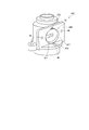
- FIG. 1 is an exploded perspective view illustrating a basic configuration of a torque detection device to which a magnetic detection module is applied.
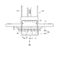
- FIG. 2A is a front view of a magnetic detection module mounting portion of a column-mounted type (non-waterproof specification) housing;
- FIG. 2B is a perspective view of FIG. 2A,
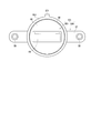
- FIG. 3A is a front view of a magnetic detection module mounting portion of a rack-mounted type (waterproof specification) housing,
- FIG. 3B is a perspective view of FIG. 3A,
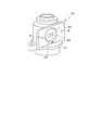
- FIG. 4 is an exploded perspective view of the magnetic detection module according to the first embodiment, FIG.
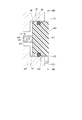
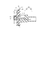
- FIG. 5A is a cross-sectional view of the cap and the case assembly
- FIG. 5B is a cross-sectional view of the torque detection device in which the case assembly is independently attached to a non-waterproof housing
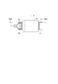
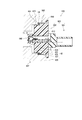
- FIG. 6A is a side view of a magnetic detection module in which a cap is attached to a case assembly
- FIG. 6B is a cross-sectional view of the torque detector in which the case assembly with the cap attached is attached to a waterproof housing.
- FIG. 7A is a plan view of a case assembly alone
- FIG. 7B is a front view taken along arrow VIIb of FIG. 7A
- FIG. 8A is a plan view showing a state where a cap is attached to the case assembly
- 8B is a front view taken along the arrow VIIIb in FIG.
- FIG. 9A is a schematic cross-sectional view of a torque detection device in which a cap according to a first modification of the first embodiment is attached to a housing
- FIG. 9B is a sectional view taken along line IXb-IXb of FIG. 9A
- FIG. 10 is a perspective view of a mounting hole of a housing to which the cap of FIG. 9A is mounted
- FIG. 11A is a schematic cross-sectional view of a torque detection device in which a cap according to a second modification of the first embodiment is attached to a housing
- 11B is a sectional view taken along line XIb-XIb of FIG. 11A
- FIG. 12 is a perspective view of a mounting hole of the housing to which the cap of FIG.
- FIG. 11A is mounted;
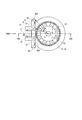
- FIG. 13A is a plan view illustrating a magnetic transmission operation between the yoke and the magnetic flux guide member in a state where the magnetic detection module is attached to the housing;
- FIG. 13B is a side view taken along arrow XIIIb in FIG. 13A.
- FIG. 14 is an axial sectional view taken along line XIV-XIV of FIG. 13A,
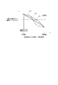
- FIG. 15 is a correlation diagram between the distance from the reference line and the magnetic permeance,
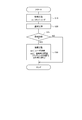
- FIG. 16 is a flowchart of a method for manufacturing a magnetic detection module,
- FIG. 17A is a plan view of a case assembly alone according to the second embodiment in which a magnetic shield member is provided in a case,
- FIG. 17B is a sectional view taken along line XVIIb-XVIIb of the magnetic shield member and the case assembly;
- FIG. 17C is a cross-sectional view of the case assembly provided with the magnetic shield member,
- FIG. 18A is a plan view of a magnetic detection module of a second embodiment in which a magnetic shield member is provided on a cap, 18B is a sectional view taken along line XVIIIb-XVIIIb in FIG. 18A,
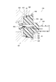
- FIG. 19 is a sectional view of a torque detection device in which the magnetic detection module according to the third embodiment is attached to a housing.
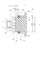
- FIG. 20 is a cross-sectional view of a torque detection device in which the magnetic detection module according to the fourth embodiment is attached to a housing.
- FIG. 21 is a schematic sectional view (1) showing a dimensional relationship between the third and fourth embodiments
- FIG. 22 is a schematic sectional view (2) showing a dimensional relationship between the third and fourth embodiments
- FIG. 23A is a cross-sectional view of the cylindrical portion taken along the line AA in FIGS. 21 and 22 showing a first example of the shape of the rotation restricting (preventing incorrect assembly) portion
- FIG. 23B is a front view of a mounting hole of the housing as viewed in the direction of arrow B in FIGS. 21 and 22, showing a first example of the shape of the rotation restricting (preventing incorrect assembly) portion
- FIG. 24A is a diagram similar to FIG. 23A, showing a shape example 2 of the rotation restricting (preventing incorrect assembly) portion
- FIG. 24A is a diagram similar to FIG. 23A, showing a shape example 2 of the rotation restricting (preventing incorrect assembly) portion
- FIG. 24B is a diagram similar to FIG. 23B, illustrating a second example of the shape of the rotation restricting (preventing incorrect assembly) portion
- FIG. 25A is a diagram similar to FIG. 23A, illustrating a third example of the shape of the rotation restricting (preventing incorrect assembly) portion.
- FIG. 25B is a diagram similar to FIG. 23B, illustrating a third example of the shape of the rotation restricting (preventing incorrect assembly) portion;
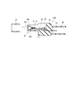
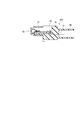
- FIG. 26A is a cross-sectional view of a cap and a case assembly using the cap of another embodiment,
- FIG. 26B is a side view of the magnetic detection module in which the cap of the other embodiment is mounted on the case assembly;
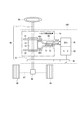
- FIG. 27 is a schematic configuration diagram of an electric power steering device to which the torque detection device is applied.
- the detection device of the present embodiment functions as a torque detection device that detects a steering torque in an electric power steering device. Further, the magnetic detection module of the present embodiment is applied to this torque detection device.
- the first and second embodiments correspond to [Disclosure of First Group].
- the third and fourth embodiments also correspond to [Disclosure of Second Group].
- the form in which the O-ring as the sealing material is mounted in the third embodiment also corresponds to [Disclosure of First Group].
- the torque detection device 10 includes a magnetic detection module 90, and detects a torque based on a magnetic flux generated according to the input torque.
- the torque detecting device 10 includes an element housed in the housing 40 mounted on the vehicle, and an element configured as the magnetic detection module 90 and attached to the housing 40.
- Elements housed in the housing 40 include the torsion bar 13, the multi-pole magnet 14, a pair of yokes 31, 32, and the like.
- Elements configured as the magnetic detection module 90 include the magnetic flux guide members 601 and 602 and the magnetic sensors 71 and 72.
- the torsion bar 13 has one end fixed to the input shaft 11 and the other end fixed to the output shaft 12 with fixing pins 15, respectively, and connects the input shaft 11 and the output shaft 12 coaxially with the center axis O.
- the torsion bar 13 is a rod-shaped elastic member, and converts the steering torque applied to the steering shaft 94 into a torsional displacement.
- the multipole magnet 14 is fixed to the input shaft 11 and has N poles and S poles arranged alternately in the circumferential direction.
- the pair of yokes 31 and 32 are formed of a soft magnetic material, and are fixed to the output shaft 12 outside the multipole magnet 14.
- Each of the yokes 31 and 32 has a ring portion 35 and 36 facing each other with a gap in the axial direction, and a plurality of claws 33 extending in the axial direction from the inner peripheral edge of each ring portion 35 and 36 toward the counterpart ring portion. , 34.
- the same number of claws 33 and 34 as the N pole and S pole of the multipole magnet 14 are provided at equal intervals around the entire circumference along the inner peripheral edges of the ring portions 35 and 36.
- the claws 33 of the one yoke 31 and the claws 34 of the other yoke 32 are alternately arranged while being shifted in the circumferential direction.
- the pair of yokes 31, 32 forms a magnetic circuit in the magnetic field generated by the multipole magnet 14.
- the center axis O may be defined based on any of them.
- the center axes O of the yokes 31, 32 are basically described with reference to the yokes 31, 32 for which the facing relationship with the magnetic flux guiding members 601 and 602 is noted.
- the axial and radial directions of the torsion bar 13, the multipole magnet 14, the pair of yokes 31, 32, and the like are simply referred to as "axial direction” and "radial direction.”
- the magnetic flux guide members 601 and 602 of the magnetic detection module 90 are formed of a soft magnetic material, and the pair of yokes 31 and 32 and the main body 600 are axially opposed to each other to guide magnetic flux of a magnetic circuit to the magnetic sensors 71 and 72. .
- a pair of magnetic flux guide members 601 and 602 facing each other in the axial direction are provided.
- the yoke 31 and the magnetic flux guiding member 601 arranged on the first shaft 11 side in FIG. 1 are referred to as “upper yoke 31” and “upper magnetic flux guiding member 601”.
- the yoke 32 and the magnetic flux guiding member 602 disposed on the second shaft 12 side are referred to as “the lower yoke 32” and “the lower magnetic flux guiding member 602”.
- the upper magnetic flux guiding member 601 faces the upper yoke 31, and the lower magnetic flux guiding member 602 faces the lower yoke 32.
- One set of magnetic flux guide members 601 and 602 of the present embodiment has two sets of extending portions 61 and 62 branched from the main body 600. Specifically, the extending portions 61 and 62 extend from the main body 600 radially outward of the yokes 31 and 32. The two magnetic sensors 71 and 72 are arranged between the extending portions 61 and 62, respectively. The extension portions 61 and 62 have a step in the axial direction so that a gap is minimized in a portion where the magnetic sensors 71 and 72 are arranged.
- the magnetic sensors 71 and 72 detect magnetic fluxes induced by the magnetic flux guiding members 601 and 602 from the ring portions 35 and 36 of the pair of yokes 31 and 32, convert the magnetic fluxes into voltage signals, and perform external processing via a harness. Output to the device.
- the magnetic sensors 71 and 72 are configured by a substantially rectangular parallelepiped IC package in which a hall element, a magnetoresistive element, and the like are resin-molded.
- the magnetic detection module 90 includes two magnetic sensors 71 and 72 and redundantly outputs two values as steering torque to the processing device. With such a redundant configuration, even if one of the information becomes unusable due to a failure of the magnetic sensor or the arithmetic circuit, the processing device can continue the control.
- FIG. 27 a schematic configuration of an electric power steering device to which the torque detection device is applied will be described with reference to FIG.
- the electric power steering device 100 shown in FIG. 27 is a column assist type
- the present invention can be similarly applied to a rack assist type electric power steering device.
- a torque detection device 10 for detecting a steering torque is installed on a steering shaft 94 connected to the steering wheel 93.
- a pinion gear 96 is provided at an end of the steering shaft 94, and the pinion gear 96 is engaged with a rack shaft 97.
- a pair of wheels 98 are rotatably connected to both ends of the rack shaft 97 via tie rods or the like. The rotational motion of the steering shaft 94 is converted into linear motion of the rack shaft 97 by the pinion gear 96, and the pair of wheels 98 is steered.
- the torque detecting device 10 is provided between the input shaft 11 and the output shaft 12 constituting the steering shaft 94, detects a steering torque applied to the steering shaft 94, and outputs the steering torque to the ECU 91.
- the ECU 91 controls the output of the motor 92 according to the detected steering torque.
- the steering assist torque generated by the motor 92 is reduced through the reduction gear 95 and transmitted to the steering shaft 94.
- a housing 401 shown in FIGS. 2A and 2B is a column-mounted housing provided on a steering shaft of the electric power steering device.
- a housing 402 shown in FIGS. 3A and 3B is a rack-mounted housing provided on a rack shaft that connects a pinion gear at the tip of a steering shaft and a wheel.
- the rack-mounted type housing 402 is in an environment where rainwater or the like is exposed to the road surface when the vehicle is running or the like, and it is necessary to provide a seal material on the mounting portion in order to prevent water from entering the housing through a gap between the mounting portions. is there.
- the column-mounted housing 401 provided in the vehicle cabin there is no risk of water infiltration, so that there is no need to provide a sealant on the mounting portion.
- non-waterproof housing 401 there are a non-waterproof housing 401 and a waterproof housing 402 depending on the mounting location of the torque detection device 10 in the vehicle.
- the housing 401 corresponds to a “housing of a first specification”
- the housing 402 corresponds to a “housing of a second specification”.
- water of “waterproof” means not only pure water but also any liquid that may enter the housing.
- Each of the housings 401 and 402 has a substantially cylindrical shape with the axis O as a central axis, and a flat mounting plate 400 is formed on a part of the outer periphery.
- the mounting plate 400 has mounting holes 41 and 42 formed over a plane including the central axis O, and fixing holes 48 such as bolts are formed on both circumferential sides of the mounting holes 41 and 42.
- the two-dot chain line indicates a portion where the flange 57 shown in FIGS. 7B and 8B abuts, and the fixing hole 48 corresponds to the position of the fixing hole 58 of the flange 57.
- the mounting hole 41 is formed in a substantially rectangular shape.
- One rotation restricting groove 44 is formed at the center lower part of the mounting hole 41, and two rotation restricting grooves 45 are formed on both sides of the mounting hole 41.
- the rotation regulating groove 44 in the lower center is formed relatively shallow, and the rotation regulating groove 45 in the upper part on both sides is formed relatively deep. The function of the rotation regulating grooves 44 and 45 will be described later with reference to FIG. 5B.
- the mounting hole 42 has a substantially rectangular case hole 421 on the far side in the depth direction, and a circular seal hole 422 in the middle in the depth direction. , And a circular spigot hole 423 on the end face side.
- One rotation regulating groove 471 is formed at the upper center of the spigot hole 423 so as to be continuous with the spigot hole 423. The function of the rotation restricting groove 471 will be described later with reference to FIG. 6B.
- an object is to provide a magnetic detection module that can be selectively attached to two types of housings 401 and 402 having different specifications by a simple configuration change using common components. I do.
- the first embodiment reflects the basic technical idea of sharing the case, and the second embodiment is different from the first embodiment in that a magnetic shield member that blocks external magnetic noise is further provided. It is provided.
- the numbers of the embodiments are given to the third digits following “10” and “90” for the reference numerals of the detection device and the magnetic detection module of each embodiment.
- the reference numerals of the constituent members in the case of a configuration unique to the embodiment, the number of the embodiment is similarly assigned to the third digit, and in the case of substantially the same configuration as the above-described embodiment, the reference numeral of the above-described embodiment is used. Invite.
- the magnetic detection module 901 includes a case assembly 500 and a cap 801.
- the case assembly 500 includes a case 501, magnetic flux guide members 601 and 602, magnetic sensors 71 and 72, and a substrate 70 housed in the box 51 of the case 501.
- the magnetic flux guiding members 601, 602 and the magnetic sensors 71, 72 are as described above with reference to FIG.
- the substrate 70 is provided with an output circuit for sensor signals in addition to the magnetic sensors 71 and 72.
- the case 501 is formed of resin, and has a rectangular parallelepiped box portion 51, a connector portion 56 to which a harness for transmitting a signal to an external processing device is connected, and a fixing hole 58 for attachment to the housings 401 and 402. It has a formed flange portion 57 and the like. Terminals 73 connected to the substrate 70 are insert-molded between the bottom of the box 51 and the bottom of the connector 56.
- the substantially rectangular substrate 70 on which the magnetic sensors 71 and 72 are mounted is installed on the bottom of the box 51.
- the open end 52 side of the box portion 51 is set to the upper side, and the bottom side of the box portion 51 is set to the lower side.
- the side of the box 51 where the magnetic sensors 71 and 72 are mounted is defined as the front, and the connector 56 is defined as the rear.
- An end portion of the case 501 located forward from the flange portion 57 of the box portion 51 forms an insertion portion 53.
- a diagram viewed from the opening end 52 side is shown as a plan view
- a diagram viewed from the insertion portion 53 side is shown as a front view.
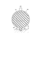
- “in a plan view” means “when viewed from the opening end 52 side”.
- the insertion portion 53 has a rectangular parallelepiped shape including a front wall 531, a side wall 532, and a bottom wall 533.
- Projections 55 are formed at the edges of the side walls 532 on both sides on the side of the opening end 52, which protrude upward and serve as an “erroneous assembly prevention part” and a “rotation restriction part”.
- a projection 54 as a “mis-assembly preventing portion” and a “rotation restricting portion” protruding downward is provided at a central portion in the left-right direction and near the flange portion 57 in the front-rear direction. Is formed.
- the “mis-assembly prevention section” enables the case 501 or the cap 801 to be assembled only in a posture positioned at a predetermined relative angle when the case 501 or the cap 801 is assembled to the housing 40, and prevents erroneous assembly in a posture positioned other than the predetermined relative angle.
- the “rotation restricting section” restricts rotation with respect to the housing 40 after the case 501 or the cap 801 is assembled to the housing 40.
- Each of the pair of magnetic flux guide members 601 and 602 includes a main body 600 that has a rectangular band shape in a plan view and collects magnetic flux, and two extending portions 61 and 62 extending from the main body 600 in the orthogonal direction.
- the parts 61 and 62 are installed so as to sandwich the magnetic sensors 71 and 72 in the vertical direction.
- the magnetic sensors 71 and 72 are arranged between the pair of magnetic flux guide members 601 and 602.
- the magnetic flux guiding members 601 and 602 are configured such that at least a part of the main body 600 faces the ring portions 35 and 36 of the cylindrical yokes 31 and 32 provided in the housing 40, and a magnetic flux from a magnetic circuit formed on the yokes 31 and 32. Is induced.
- the rectangular belt-shaped shapes of the magnetic flux guide members 601 and 602 are simply referred to as “linear”. The detailed configuration and operation of the magnetic flux guide members 601 and 602 will be described later.
- the box portion 51 of the case 501 is potted from the opening end 52 with the molten resin, and the stored components are fixed.
- a lid 59 for closing the opening end 52 may be used as a separate component.
- the upper magnetic flux guide member 601 can be insert-molded integrally with the lid 59.
- the opening end 52 may be closed with only the potting of the molten resin without using the lid 59 or with only the lid 59 without potting.
- the case assembly 500 in which the magnetic flux guide members 601 and 602, the magnetic sensors 71 and 72, and the substrate 70 are housed in the case 501 is configured.
- the case assembly 500 can be independently attached to the non-waterproof housing 401.
- the cap 801 attached to the insertion portion 53, the cap 801 can be attached to the waterproof housing 402.
- the single case assembly 500 constitutes a "magnetic detection module".
- the partner to which the cap 801 is mounted is the case assembly 500 in terms of the manufacturing process, but it can also be expressed as "the cap 801 is mounted on the case 501" from the viewpoint of parts.
- the cap 801 is formed of resin, and a receiving hole 83 into which the insertion portion 53 of the case 501 is inserted is formed in an end surface of the disk-shaped cap body 811 on the case 501 side.
- the receiving hole 83 is opened in a rectangular shape corresponding to the shape of the insertion portion 53 of the case 501, and the depth of the receiving hole 83 is deeper than the thickness of the cap body 811.
- Projection accommodation grooves 85 into which the projections 55 are inserted are formed in both upper portions of the receiving holes 83. Thereby, when inserting the insertion portion 53 into the receiving hole 83, it is prevented that the insertion portion 53 is inserted in the opposite direction by 180 °.
- a sealing portion 84 which is connected to the end surface of the cap body 811 on the side opposite to the case 501 and covers the bottom of the receiving hole 83 and has a bag shape is formed.
- the sealing portion 84 projects in a rectangular parallelepiped shape from the cap body 811 to the opposite side of the case 501, and the outer wall is formed to be slightly larger than the inner wall at the bottom of the receiving hole 83. In short, communication between the outer wall of the sealing portion 84 and the inner wall of the receiving portion 83 is blocked so that water does not leak.
- An outer flange 863 on the opening surface side of the receiving hole 83 and an inner flange 88 on the protruding side of the sealing portion 84 are provided in parallel on the outer periphery of the cap body 811, and the outer flange 863 and the inner flange 88 are provided. And an outer peripheral groove 82 is formed.
- a projecting portion 871 is formed at the upper center of the outer flange 863 so as to protrude outward in the radial direction, as a “erroneous assembly preventing portion” and also as a “rotation restricting portion”.
- O An O-ring 89 as a “sealant” is mounted in the outer peripheral groove 82. At this time, the inner peripheral surface of the O-ring 89 contacts the bottom wall of the outer peripheral groove 82.
- the O-ring 89 may be attached to the outer peripheral groove 82 before assembling the cap 801 and the case 501, or may be provided in the outer peripheral groove 82 after assembling the cap 801 and the case 501.
- FIG. 5B shows the torque detection device 101 in which the case assembly 500 is independently mounted in the mounting hole 41 of the non-waterproof specification housing 401.
- the insertion portion 53 of the case 501 is inserted into the substantially rectangular mounting hole 41.
- the lower protrusion 54 is inserted into the rotation restricting groove 44, and the protrusions 55 on both upper sides are inserted into the rotation restricting groove 45. Therefore, when the case assembly 500 is assembled to the housing 401, the case assembly 500 is prevented from being erroneously assembled in the mounting hole 41 in the opposite direction by 180 °. After the assembly, the rotation of the case assembly 500 with respect to the housing 401 is restricted.
- FIG. 6B shows the torque detection device 101 in which the magnetic detection module 901 with the cap 801 mounted on the case assembly 500 is mounted in the mounting hole 42 of the waterproof housing 402.
- the sealing portion 84 of the cap 801 is inserted into the substantially rectangular case hole 421, the inner flange 88 is inserted into the seal hole 422, and the outer flange 863 is inserted into the spigot hole 423.
- the protrusion 871 into the rotation regulating groove 471, when the magnetic detection module 901 is assembled to the housing 402, it is prevented from being erroneously assembled in the mounting hole 42 in the opposite direction by 180 °. After the assembly, the rotation of the magnetic detection module 901 with respect to the housing 402 is restricted.
- 9A and 11A are schematic cross-sectional views showing a state where the cap 801 is attached to the housing 402.
- the schematic cross-sectional view shows a schematic cross-section in which the cap 801 and the case 501 are fused, and an accurate illustration of the internal structure as in FIG. 6B is omitted.
- a prismatic portion covered by the bag portion 84 protruding from the tip end surface of the cap body 811 is referred to as a “sensor portion 840”.
- the magnetic sensors 71 and 72 are housed in the sensor section 840.
- “contained” includes a configuration that is molded.
- FIGS. 9B and 11B are radial cross-sectional views showing the “erroneous assembly prevention part” and the “rotation restriction part” provided on the cap 801 or the housing 402 on the base end side of the cap 801.
- 10 and 12 are perspective views of the mounting hole 42 of the housing 402 corresponding to FIG. 3B.
- a projection 871 similar to that of FIG. 4 and the like is formed on the upper portion of the cap body 811, and the radially outward direction is provided on the lower portion of the cap body 811 at a predetermined interval.
- a pair of biprotrusions 872 projecting substantially in parallel with each other is formed.
- a rotation restricting convex portion 472 sandwiched between the double protruding portions 872 is formed on the other hand.
- a portion corresponding to the protrusion 871 on the end face of the housing 402 is a flat end face without unevenness.
- the cap 801 is attached to the housing 402 at a rotation position where the double protrusion 872 sandwiches the rotation restricting protrusion 472, so that the double protrusion 872 functions as a “rotation restricting portion”.
- the protrusion 871 interferes with the rotation restricting projection 472 of the housing 402. Function as As described above, in the first modified example, the protrusion 871 and the double protrusion 872 of the cap body 811 use the rotation control protrusion 472 of the housing 402 to function as the “error assembly prevention unit” and the “rotation control unit”. To share.
- a projection 874 projecting radially outward is formed at the lower portion of the cap body 811.
- the upper part of the cap body 811 has a simple cylindrical surface without irregularities.
- a rotation regulating groove 474 in which the tip of the projection 874 is engaged is formed in the pedestal 46 below the mounting hole 42.
- An interference projection 473 is formed at the edge of the mounting hole 42 opposite to the rotation regulating groove 474.
- the cap 801 is assembled to the housing 402 at a rotational position where the tip of the projection 874 engages with the rotation regulating groove 474, so that the projection 874 functions as a “rotation regulating section”.
- the projection 874 interferes with the interference projection 473 of the housing 402. Function.
- the projection 874 of the cap body 811 functions as the “erroneous assembly prevention unit” using the interference projection 473 of the housing 402 and uses the rotation restricting groove 474 of the housing 402. Thus, it functions as a “rotation restriction unit”.
- FIGS. 13A to 14 are plan views and side views showing the magnetic flux transmitting action between the yokes 31 and 32, the magnetic flux guiding members 601 and 602, and the magnetic sensors 71 and 72 when the case assembly 500 is attached to the housing.
- the plan view means a view from the first shaft 11 side in the axial direction
- the side view means a view from the radial direction.
- the “plan view” is strictly a radial cross-sectional view obtained by cutting the multipole magnet 14 and the claws 33 and 34 of the yokes 31 and 32 at the upper part of the upper magnetic flux guide member 601, but from the viewpoint of the magnetic flux guide member 601. This is referred to as "plan view”. Although only the lower yoke 32 is actually visible in the radial cross section, the reference numerals including the upper yoke 31 are denoted by “31, 32” for convenience of explanation.
- a“ reference line X ” extending in the left-right direction through the central axis O is described.
- the reference line X is defined as an imaginary straight line connecting an intermediate position between the two magnetic sensors 71 and 72 and the central axis O.
- the two magnetic sensors 71 and 72 are arranged symmetrically with respect to the reference line X.
- the reference line X is defined as a virtual straight line connecting the magnetic sensor and the central axis O.
- FIG. 13B The side view of FIG. 13B is a view of the magnetic sensors 71 and 72 viewed from the radial outside along the reference line X.
- the two-dot chain line indicates the outer shape of the claws 33 and 34.
- illustration of the torsion bar 13 and the multipole magnet 14 is omitted.
- the axial sectional view of FIG. 14 is a sectional view on a plane including the central axis O and the reference line X.
- the illustration of the torsion bar 13 is omitted in the axial cross-sectional view, and only the outer shape of the multipole magnet 14 is shown.
- the main bodies of the magnetic flux guiding members 601 and 602 are formed in a rectangular band shape symmetrical with respect to the reference line X, that is, in a straight line shape in plan view.
- the longitudinal sides of the magnetic flux guide members 601 and 602 are straight lines orthogonal to the reference line X.
- the magnetic flux guide members 601 and 602 have extending portions 61 and 62 extending radially outward from the main body 600, and a “branch portion of the main body 600 to the extending contact portions 61 and 62” is referred to as an S portion.
- the “branch site to the extension portions 61, 62” means substantially near the magnetic sensors 71, 72.
- the “S part” is the same symbol as the S pole of the multipole magnet 14, but their distinction is obvious and there is no risk of confusion.
- peripheral ends 63 and 64 of the main body 600 are referred to as “peripheral ends 63 and 64 of the main body 600”.
- ”And is indicated by broken-line hatching in the figure.
- the distance ds from the S portion to the central axis O is shorter than the distance de from the peripheral ends 63 and 64 to the central axis O.
- the magnetic flux guide members 601 and 602 face the annular surfaces of the yokes 31 and 32 with a constant gap inside the axial direction in a side view and a sectional view in the axial direction. It is relatively large at 65 and becomes smaller toward the peripheral ends 63 and 64.
- the S portion which is a branch portion to the extension portions 61 and 62, has a larger opposing area than the peripheral end portions 63 and 64, so that the magnetic flux per unit area between the magnetic flux guiding members 601 and 602 and the yokes 31 and 32 is increased. Permeance increases.
- the meaning of “per unit area” is to clearly indicate that the area of the range in which the magnetic permeance is compared for each part is the same. In the following description, the description of “per unit area” is omitted each time, and “magnetic permeance” is interpreted as meaning “magnetic permeance per unit area”.
- the two magnetic sensors 71 and 72 are arranged between the extending portions 61 and 62, respectively.
- the extension portions 61 and 62 are bent in the axial direction so as to minimize the gap in a portion where the magnetic sensors 71 and 72 are arranged, and have a step.
- FIG. 15 shows a correlation diagram of the magnetic permeance between the magnetic flux guiding members 601 and 602 and the yokes 31 and 32 with respect to the distance or the rotation angle from the reference line X and the magnetic permeance.
- the magnetic flux guiding members 601 and 602 are formed of a single soft magnetic material
- the magnetic permeance P increases as L decreases.
- the gap between the magnetic flux guiding members 601 and 602 and the yokes 31 and 32 is constant, but the facing area becomes smaller from the intermediate portion 65 toward the peripheral ends 63 and 64, so that the magnetic force of the intermediate portion 65 is reduced.
- the permeance is larger than the magnetic permeance of the peripheral ends 63 and 64.
- the correlation characteristic may be any characteristic such as a straight line like P1, a simple curve without inflection point like P2, an S-shaped curve like P3, or a step-like broken line. Good.
- the magnetic sensors 71 and 72 are installed on the extending portions 61 and 62 branched from the main body 600 near the intermediate portion 65, and the magnetic flux guiding members 601 and 602 branch from the main body 600 to the extending contact portions 61 and 62, respectively. It substantially means “near the magnetic sensors 71 and 72”. Then, the magnetic flux guiding members 601 and 602 are branching portions to the extending contact portions 61 and 62, and have a “per unit area between the magnetic flux guiding members 601 and 602 and the yokes 31 and 32, compared to the peripheral ends 63 and 64. The magnetic permeance of "is increased. Thereby, the signals of the magnetic sensors 71 and 72 can be increased.
- the symbol S represents “step”.
- the magnetic flux guide members 601 and 602 the magnetic sensors 71 and 72, the substrate 70, and the like are stored in the box portion 51 of the case 501.
- the molten resin is potted in the remaining space of the box portion 51, and the magnetic sensors 71 and 72 are fixed.
- the box portion 51 may be covered with a lid 58.
- the case assembly 500 is manufactured.
- the selection result is determined. If it is attached to the waterproof housing 402, YES is determined in S25, and the process proceeds to S30. If it is attached to the non-waterproof housing 401, NO is determined in S25, and the process ends. In this case, the case assembly 500 is used alone without the cap 801 attached.
- the cap 801 is mounted on the case 501 and fixed.
- the insertion portion 53 formed at the end of the case 501 is inserted into the receiving hole 83 formed in the cap 801. Thereafter, the joint between the insertion portion 53 of the case 501 and the receiving hole 83 of the cap 801 is welded by laser welding or the like.
- the joining portion surrounding the magnetic sensors 71 and 72 is welded one round. Thus, water leakage from the bottom of the receiving hole 83 can be prevented.
- the cap 801 may be fixed with an adhesive in the mounting step. Further, when the molten resin is potted in the storage step, it is preferable that the curing of the potting and the curing of the adhesive are performed simultaneously. Thus, the cycle time can be reduced.
- the specification of attachment to the housing 40 can be changed depending on the presence or absence of the cap 801.
- a magnetic detection module in which a cap 801 provided with a sealing material 89 is attached to a case 501 is supplied to a waterproof housing 402.
- the case assembly 501 in which the cap 801 is not attached to the non-waterproof housing 401 is supplied alone as a magnetic detection module. Therefore, for example, when the case 501 is manufactured by resin molding, only one type of mold is required for the case 501, and inventory management is simplified.
- the magnetic shield member is formed of a soft magnetic material such as iron or permalloy, and blocks external magnetic noise.
- the rectangular frame-shaped magnetic shield member 37 is provided in the insertion portion 53 of the case assembly 500 which is independently attached to the non-waterproof housing 401. Specifically, after the molten resin is potted to the case 501, the magnetic shield member 37 is covered so as to surround the magnetic sensors 71 and 72 from all sides. Therefore, magnetic noise toward the magnetic sensors 71 and 72 is effectively shut off.
- a pair of arch-shaped magnetic shield members 38 are provided on a cap 801 of a magnetic detection module 902 attached to a waterproof housing 402.
- the pair of magnetic shield members 38 are provided so as to surround the sealing portion 84 from above and below.
- the magnetic shield member 38 is arranged such that the center line Ds in the depth direction overlaps the magnetic sensors 71 and 72. Therefore, magnetic noise toward the magnetic sensors 71 and 72 is effectively shut off.
- the torque detecting device 103 of the third embodiment includes a housing 402 having an inner wall having a cylindrical mounting hole 42, and a magnetic detection module 903 mounted in the mounting hole 42.
- a pair of yokes 31 and 32 for transmitting a magnetic flux generated according to the magnitude of the torque are provided inside the housing 402.
- the magnetic detection module 903 detects the magnetic flux transmitted from the yokes 31, 32 by one or more magnetic sensors 71, 72.
- the magnetic detection module 903 of the third embodiment has a disk-shaped cap 803 attached to the tip of a case 501, as in the first embodiment.
- the outer peripheral surface of the cap body 813 in the cap 803 faces the inner wall of the mounting hole 42.
- the outer peripheral groove 82 is formed between the outer flange 863 and the inner flange 88, whereas the inner flange is provided in the cap 803 of the third embodiment.
- a radial step 823 is formed on the outer periphery.
- the O-ring 89 is attached to the step portion 823 as a sealing material for shaft sealing, but the O-ring 89 may not be provided in other embodiments.
- the step portion 823 is formed by a step between a large diameter portion 866 on the base end side of the cap body 813 and a small diameter portion 865 on the front end side.
- the large diameter part 866 and the small diameter part 865 correspond to a “large shaft part” and a “small shaft part”.
- the mounting hole 42 has a case hole 424, a small-diameter hole 425, a large-diameter hole 426, and a chamfered portion 427 in order from the end face 428 side.
- the large diameter hole 426 and the small diameter hole 425 correspond to “large hole” and “small hole”.
- the large diameter portion 866 of the cap 803 is inserted into the large diameter hole 426, and the small diameter portion 865 is inserted into the small diameter hole 425.
- a flange portion 868 abutting on the end surface 428 of the housing 402 is formed.
- a sensor section 840 protrudes from the tip end surface of the cap body 813. The tip of the sensor section 840 is inserted between the ring sections 35 and 36 of the pair of yokes 31 and 32.
- the configuration, operation, and effect related to the dimensional relationship are the same as the configuration, operation, and effect of the torque detection device 104 according to the fourth embodiment, and will be described together in the fourth embodiment.
- the torque detecting device 104 of the fourth embodiment includes a housing 402 having an inner wall having a cylindrical mounting hole 42, and a magnetic detection module 904 mounted in the mounting hole 42.
- a pair of yokes 31 and 32 for transmitting magnetic flux generated according to the magnitude of the torque are provided inside the housing 402.
- the magnetic detection module 904 detects the magnetic flux transmitted from the yokes 31, 32 by one or more magnetic sensors 71, 72.
- the magnetic detection module 904 is not intended to be selectively attachable to a plurality of housings, and the attachment target is limited to the housing 402 whose inner wall has the cylindrical attachment hole 42.
- an object is to prevent interference between the sensor unit 840 and a member on the housing 402 side when the magnetic detection module 904 is inserted into the housing 402.
- the magnetic detection module 904 of the fourth embodiment is configured by an integral case 504 instead of a configuration in which a cap of another member is attached to the end of the case.
- the case 504 is integrally formed of resin in the same shape as the state where the cap 803 is attached to the case 501 in the third embodiment shown in FIG. That is, the case 501 and the cap 803 are combined to form the integrated case 504 of the fourth embodiment.
- a portion corresponding to the cap body 813 of the cap 803 of the third embodiment is referred to as a “cylindrical portion 814” in the fourth embodiment.
- the cylindrical portion 814 corresponds to a “cylindrical portion”, and faces the inner wall of the mounting hole 42.
- a sensor section 840 protrudes from the distal end surface of the cylindrical section 814.
- a form in which the cylindrical portion 814 of the case 504 of the fourth embodiment is constituted by the cap body 813 of the cap 803 as a separate member corresponds to the third embodiment.
- the O-ring 89 is attached in two forms: “selective attachment to a plurality of waterproof and non-waterproof housings” and “prevention of interference between the magnetic sensor and the housing side member”. It is positioned to satisfy two purposes.
- the configuration of the cylindrical portion 814 of the fourth embodiment and the mounting hole 42 facing the cylindrical portion 814 is the same as the cap body 813 of the third embodiment and the mounting hole 42 facing the outer peripheral surface of the cap body 813.
- the configuration is substantially the same.
- the attachment hole 42 has a large-diameter hole 426 formed on the opening side and a small-diameter hole 425 formed behind the large-diameter hole 426.
- the cylindrical portion 814 has a flange portion 868 abutting on the end surface 428 of the housing, a large-diameter portion 866 inserted into the large-diameter hole 426, and a proximal end toward the distal end where the magnetic sensors 71 and 72 are arranged.
- the small diameter portion 865 is inserted into the small diameter hole 425.
- the O-ring 89 is mounted as a sealant on the outer periphery of the small diameter portion 865, but the O-ring 89 may be omitted in other embodiments.
- the O-ring 89 is used for a shaft seal between the small-diameter hole 425 and the inner wall.
- FIGS. 9A and 11A The cross-sectional views of the torque detecting device 104 in FIGS. 21 and 22 are schematic as in FIGS. 9A and 11A.
- the magnetic sensors 71 and 72 are housed in a “sensor part 840” which is a prism-shaped part protruding from the distal end surface of the cylindrical part 814. “Contained” includes a configuration that is molded.
- the sensor unit 840 interferes with a member on the housing 402 side due to a positional shift or an inclination when the magnetic detection module 904 is inserted into the mounting hole 42, the magnetic sensors 71 and 72 may be damaged or a characteristic change may occur. Therefore, in the fourth embodiment, interference between the sensor unit 840 and members on the housing 402 side is prevented.
- the sensor section 840 is inserted between the ring sections 35 and 36 of the pair of yokes 31 and 32 facing each other.
- the magnetic sensors 71 and 72 detect the magnetic flux.
- the minimum distance between the sensor unit 840 and the ring units 35 and 36 is defined as “sensor margin ⁇ ”.
- the sensor margin ⁇ is determined based on the distance between the ring units 35 and 36. Is half the length obtained by subtracting the thickness.
- FIG. 21 and FIG. 22 show an embodiment of two patterns having different dimensional relationships of diameters.
- the symbols for the dimensions of each part are defined as follows.
- the “one-side fitting gap” corresponds to half the fitting gap between the diameter of the hole and the diameter of the shaft.
- the letter “h” in the symbol represents the housing, and “s” represents the sensor.
- ⁇ ds1 outer diameter of the large-diameter portion 866 ⁇ 1: one-side fitting gap between the large-diameter hole 426 and the large-diameter portion 866
- ⁇ ds2 outer diameter of small-diameter portion 865 ⁇ 2: one-side fitting gap between small-diameter hole 425 and small-diameter portion 865
- the one-sided fitting gap ⁇ 1 between the large-diameter hole 426 and the large-diameter portion 866 is set to a small gap of, for example, less than 0.1 mm. That is, the fitting between the large diameter hole 426 and the large diameter portion 866 has a spigot structure. Therefore, accuracy such as coaxiality and squareness when the cylindrical portion 814 is inserted into the mounting hole 42 is ensured.
- the gap ⁇ 1 is set smaller than the sensor margin ⁇ ( ⁇ 1 ⁇ ).
- gap ⁇ 1 is set extremely smaller than sensor margin ⁇ ( ⁇ 1 ⁇ ⁇ ).
- the one-side fitting gap ⁇ 2 between the small-diameter hole 425 and the small-diameter portion 865 may be equal to or larger than the gap ⁇ 1.
- the ring portions 35, 36 of the yokes 31, 32 from the insertion end of the large diameter hole 426 that is, the boundary between the chamfered portion 427 and the large diameter hole 426.
- the distance to the outer edge is defined as “housing-side distance Lh1”.
- the distance from the boundary between the large-diameter portion 426 and the small-diameter portion 425 to the tip of the sensor unit 840 is defined as “sensor-side distance Ls1”.
- the housing-side distance Lh1 is set to be longer than the sensor-side distance Ls1.
- the one-side fitting gap ⁇ 2 between the small-diameter hole 425 and the small-diameter portion 865 is set to a minute gap of, for example, less than 0.1 mm. That is, the fitting between the small diameter hole 425 and the small diameter portion 865 has a spigot structure. Therefore, accuracy such as coaxiality and squareness when the cylindrical portion 814 is inserted into the mounting hole 42 is ensured.
- the gap ⁇ 2 is set smaller than the sensor margin ⁇ ( ⁇ 2 ⁇ ).
- gap ⁇ 2 is set to be extremely smaller than sensor margin ⁇ ( ⁇ 2 ⁇ ⁇ ).
- the one-sided fitting gap ⁇ 1 between the large-diameter hole 426 and the large-diameter portion 866 may be equal to or larger than the gap ⁇ 2.
- the outer edges of the ring portions 35 and 36 of the yokes 31 and 32 from the insertion end of the small diameter hole 425 (that is, the boundary between the large diameter hole 426 and the small diameter hole 425).
- the distance from the distal end surface of the cylindrical portion 814 to the distal end of the sensor portion 840 is defined as “sensor-side distance Ls2”.
- the housing-side distance Lh2 is set to be longer than the sensor-side distance Ls2.
- the sensor portion 840 can be used. Of the tip position is suppressed to be smaller than the sensor margin ⁇ . Therefore, when the magnetic detection module is inserted, it is possible to prevent interference between the sensor unit 840 and the yokes 31, 32 that are the housing-side members.
- Patent Literature 2 Japanese Patent No. 4753545
- a magnetic ring is arranged radially outward of a magnetic yoke and radially opposes the magnetic yoke.
- it is effective to secure concentricity between the magnetic ring and the magnetic yoke by positioning, but the positional accuracy in the rotational direction does not significantly affect the performance.
- the rotation direction of the cylindrical portion 814 with respect to the mounting hole 42 Is important. It is also important to prevent the magnetic detection module 904 from being mounted in the wrong direction, for example, by 180 °.
- FIGS. 23A, 24A, and 25A show cross sections of the cylindrical portion 814 taken along the line AA in FIGS. 21 and 22.
- FIGS. 23B, 24B, and 25B show front views of the mounting holes of the housing as viewed in the direction of arrow B in FIGS. It should be noted that the illustration of the changed portions of the assembly cross sections in FIGS. 21 and 22 corresponding to the respective shapes in FIGS. 23A to 25B is omitted. Further, for example, when used in a column mounting type that does not require waterproofing, the O-ring 89 may be omitted in each drawing.
- a projection 875 projecting radially outward is formed at one location in the circumferential direction of the large diameter portion 866.
- a rotation restricting groove 475 is formed at a position corresponding to the mounting hole 42.
- This configuration example is similar to the configuration examples of the protrusion 871 and the rotation restricting portion 471 in FIGS. 3A, 3B, 4, and the like.
- the protrusion 871 is formed on the outer periphery of the outer flange 863 inserted into the spigot hole 423
- the protrusion 875 is formed on the outer periphery of the large diameter portion 866. Is formed.
- the rotation of the cylindrical portion 814 is regulated by the engagement of the protrusion 875 with the rotation regulating groove 475.
- the mounting can be performed only in a posture in which the relative angle between the cylindrical portion 814 and the mounting hole 42 is at a regular angle, and erroneous mounting in a posture in which the relative angle is out of the predetermined relative angle is prevented.
- the protrusion 875 and the rotation restricting groove 475 function as a “wrong assembly preventing part” and a “rotation restricting part”.
- a flat portion 876 is formed on one side of the large diameter portion 866 in the circumferential direction.
- a rotation restricting recess 476 is formed at a position corresponding to the mounting hole 42.
- the flat portion 876 corresponds to a form in which the width of the protruding portion 875 is increased and the protruding length of the large diameter portion 866 with respect to the outer diameter is reduced.
- the protruding length of the flat portion 876 with respect to the outer diameter of the large-diameter portion 866 is substantially zero.
- a flat portion 876 may be formed on the minus side (ie, the center side) of the outer diameter of the large diameter portion 866, and the outer peripheral shape of the large diameter portion 866 may be a D-shape in which a part of the circumferential direction is connected by a straight line. Good.
- the flat portion 876 engages with the rotation restricting concave portion 476, so that the flat portion 876 and the rotation restricting concave portion 476 function as an “erroneous assembly preventing portion” and a “rotation restricting portion”.
- the separating portion 877 is formed at a position apart from the circular large-diameter portion 866 in the radially outward direction.
- the separating portion 877 is connected to the flange portion 868 via a connecting portion 878 indicated by a two-dot chain line.
- a rotation regulating hole 477 is formed at a position corresponding to the mounting hole 42.
- the separation part 877 fits into the rotation restriction hole 477, so that the separation part 877 and the rotation restriction hole 477 function as an “erroneous assembly prevention part” and a “rotation restriction part”.
- the positions of the protruding portion 875, the flat portion 876, and the separating portion 877 are not limited to the illustrated positions, but may be any positions in the circumferential direction. Also, a plurality of these may be arranged in the circumferential direction. However, when functioning as the “erroneous assembly prevention section”, a plurality of rotationally symmetric positions must be arranged so that a plurality of rotationally symmetric positions do not exist. Further, as in the modification of the first embodiment shown in FIGS. 9A to 12, a protrusion may be provided on the housing 402 side.
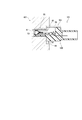
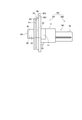
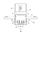
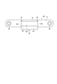
- the cap 801 in the form shown in FIGS. 4 to 8B has a bag-shaped sealing portion 84 formed at the tip, whereas the cap 801 has a bag like the magnetic detection module 905 shown in FIG.
- An unshaped cap 805 may be used.
- the distance (gap) between the opposing portions of the yokes 31, 32 and the magnetic flux guide members 601 and 602 is smaller by the thickness of the resin at the end than in the embodiment in which the sealing portion 84 is formed at the end. Sensitivity can be improved.
- the contact portion indicated by (*) in FIG. 26B be sealed with laser welding or an adhesive.
- the O-ring 89 as a sealing material is mounted on the outer peripheral groove 82 of the cap 801 and used for shaft sealing between the O-ring 89 and the inner wall of the mounting hole 42 of the housing 402.
- an O-ring, packing, gasket, or the like used for face sealing may be provided on the cap.
- the sealing material is not limited to a waterproof material, and may be an oil seal or a gas seal.
- the shape of the portion where the O-ring 89 is mounted on the outer periphery of the cap body 811 is not limited to the outer peripheral groove 82, and may be a radial step as in the third and fourth embodiments.
- attachment to the two types of housings 401 and 402 of the waterproof specification and the non-waterproof specification can be selected depending on whether or not the cap 801 is attached to the case 501.
- a cap according to each specification and put it on the case It may be attachable.
- a cap may be attached to the case as an adapter for a plurality of non-waterproof housings having different shapes and sizes of the mounting portions.
- the number of magnetic sensors provided in the magnetic detection module is not limited to two as exemplified in the above embodiment, and may be one or three or more. Further, the magnetic detection module may not include the magnetic flux guiding members 601 and 602, and the magnetic flux generated in the housing 40 may be directly transmitted from the pair of yokes 31 and 32 to the magnetic sensors 71 and 72.
- the shape of the main body of the magnetic flux guide member is not limited to a linear shape, may be an arc shape along the yoke, or the like, and the extension portion may not be provided. Further, the magnetic flux guiding member may face the pair of yokes 31 and 32 not in the axial direction but in the radial direction.
- the case 501 and the cap 801 are not limited to resin molded products, and may be made of another material that does not affect the magnetic detection.
- the method of mounting the cap 801 on the case 501 is not limited to the method of inserting the insertion portion 53 of the case 501 into the receiving hole 83 of the cap 801 and welding or bonding the joint portion. Good.
- the shapes of the erroneous assembly preventing portions and the rotation restricting portions on the housings 401 and 402 are not limited to the protrusions, grooves, and the like described in the above embodiment. Further, the positions and the numbers of the erroneous assembly preventing portion and the rotation restricting portion may be set as appropriate. Further, the present invention is not limited to a form having both functions, and may have only a mis-assembly prevention function or only a rotation regulating function. For example, the erroneous assembly preventing portion may be configured by an asymmetric shape. In addition, in the case where the purpose of preventing erroneous assembly or restricting rotation is achieved by another configuration, the erroneous assembly preventing unit or the rotation restricting unit may not be provided.
- the cylindrical portion 814 of the fourth embodiment is not limited to a cylindrical shape, and may be formed as a “cylindrical portion” including an elliptical cylindrical shape, a long cylindrical shape, a polygonal cylindrical shape, and the like. The same applies to the cap body 813 of the third embodiment.
- a sealing function by the O-ring is also ensured.
- it can be expressed using “diameter”.
- the large diameter portion and the small diameter portion are referred to as “large shaft portion”. And a "small shaft portion”.
- the large-diameter hole and the small-diameter hole of the mounting holes facing each other may be generalized as “large hole” and “small hole”.
- the direction perpendicular to the axial direction of the cylindrical portion and going from the center to the periphery is a pseudo "radial direction”
- the gap between the shaft portion and the hole on one side in the radial direction in the spigot structure is referred to as "one-side fitting gap". I just need to interpret it.
- the detection device to which the detection device of the present disclosure or the magnetic detection module of the present disclosure is applied is not limited to the torque detection device of the electric power steering device, and the magnetic flux generated according to the magnitude of the physical quantity to be detected. May be used as long as it can detect.
- the generated magnetic flux is transmitted by a pair of yokes provided inside the housing and detected by a magnetic sensor of the magnetic detection module.
- the present invention can be used as a rotation detector, a position detector, and the like that detect a magnetic flux generated in accordance with the rotation or linear movement of a movable body.
Landscapes
- Physics & Mathematics (AREA)
- General Physics & Mathematics (AREA)
- Condensed Matter Physics & Semiconductors (AREA)
- Electromagnetism (AREA)
- Health & Medical Sciences (AREA)
- Engineering & Computer Science (AREA)
- Environmental & Geological Engineering (AREA)
- Toxicology (AREA)
- Power Steering Mechanism (AREA)
Abstract
L'invention concerne un module de détection magnétique (901) pouvant être monté sélectivement sur n'importe lequel des boîtiers présents dans de multiples spécifications et différents les uns des autres en taille ou en forme d'une partie de montage, le module de détection magnétique étant destiné à détecter un flux magnétique généré à l'intérieur du boîtier. Le module de détection magnétique (901) comprend : un ou plusieurs capteurs (71, 72) permettant de détecter un flux magnétique ; un boîtier (501) dans lequel les capteurs magnétiques sont logés ; et un capuchon (801) pouvant être monté sur une extrémité du boîtier (501) et possédant à l'intérieur de ce dernier un matériau d'étanchéité (89). Le module de détection magnétique (901) peut être monté sur un boîtier présentant une première spécification dans un état dans lequel le boîtier (501) n'a pas le capuchon (801) monté sur ce dernier, et peut être monté, par l'intermédiaire du matériau d'étanchéité (89), à un boîtier présentant une seconde spécification dans un état dans lequel le boîtier (501) a le capuchon (801) monté sur ce dernier.
Priority Applications (4)
| Application Number | Priority Date | Filing Date | Title |
|---|---|---|---|
| EP22183102.7A EP4109064B1 (fr) | 2018-06-28 | 2019-06-19 | Module de détection magnétique, dispositif de détection, ensemble boîtier et procédé de production d'un module de détection magnétique |
| EP19826069.7A EP3816599B1 (fr) | 2018-06-28 | 2019-06-19 | Module de détection magnétique, dispositif de détection, ensemble boîtier et procédé de production de module de détection magnétique |
| US17/129,094 US11353521B2 (en) | 2018-06-28 | 2020-12-21 | Magnetic detection module, detection device, case assembly, and production method for magnetic detection module |
| US17/829,295 US11579211B2 (en) | 2018-06-28 | 2022-05-31 | Detection device |
Applications Claiming Priority (4)
| Application Number | Priority Date | Filing Date | Title |
|---|---|---|---|
| JP2018-123160 | 2018-06-28 | ||
| JP2018123160 | 2018-06-28 | ||
| JP2018195711A JP6908014B2 (ja) | 2018-06-28 | 2018-10-17 | 磁気検出モジュール、検出装置、ケースアセンブリ、及び、磁気検出モジュールの製造方法 |
| JP2018-195711 | 2018-10-17 |
Related Child Applications (1)
| Application Number | Title | Priority Date | Filing Date |
|---|---|---|---|
| US17/129,094 Continuation US11353521B2 (en) | 2018-06-28 | 2020-12-21 | Magnetic detection module, detection device, case assembly, and production method for magnetic detection module |
Publications (1)
| Publication Number | Publication Date |
|---|---|
| WO2020004161A1 true WO2020004161A1 (fr) | 2020-01-02 |
Family
ID=68985661
Family Applications (1)
| Application Number | Title | Priority Date | Filing Date |
|---|---|---|---|
| PCT/JP2019/024190 Ceased WO2020004161A1 (fr) | 2018-06-28 | 2019-06-19 | Module de détection magnétique, dispositif de détection, ensemble boîtier et procédé de production de module de détection magnétique |
Country Status (3)
| Country | Link |
|---|---|
| US (1) | US11579211B2 (fr) |
| EP (1) | EP4109064B1 (fr) |
| WO (1) | WO2020004161A1 (fr) |
Cited By (1)
| Publication number | Priority date | Publication date | Assignee | Title |
|---|---|---|---|---|
| US11372125B2 (en) * | 2019-04-19 | 2022-06-28 | Tsinghua University | Amphibious portable magnetism detector |
Families Citing this family (2)
| Publication number | Priority date | Publication date | Assignee | Title |
|---|---|---|---|---|
| JP7494819B2 (ja) | 2021-08-24 | 2024-06-04 | 株式会社デンソー | トルク検出装置 |
| EP4421466B1 (fr) * | 2021-10-22 | 2025-06-11 | Denso Corporation | Système de détection de couple |
Citations (6)
| Publication number | Priority date | Publication date | Assignee | Title |
|---|---|---|---|---|
| WO1997004318A1 (fr) * | 1995-07-21 | 1997-02-06 | Matsushita Electric Industrial Co., Ltd. | Capteur de vitesse de rotation magnetique |
| JP2008249598A (ja) * | 2007-03-30 | 2008-10-16 | Jtekt Corp | トルク検出装置 |
| US20110167920A1 (en) * | 2008-07-14 | 2011-07-14 | Continental Teves Ag & Co. Ohg | Torque sensor arrangement with rotational angle index detection |
| JP4753545B2 (ja) | 2004-04-08 | 2011-08-24 | 株式会社ジェイテクト | トルク検出装置及びこれの製造方法 |
| JP2012237728A (ja) * | 2011-05-13 | 2012-12-06 | Denso Corp | トルクセンサ |
| JP5153490B2 (ja) | 2008-07-11 | 2013-02-27 | カヤバ工業株式会社 | トルクセンサ |
Family Cites Families (20)
| Publication number | Priority date | Publication date | Assignee | Title |
|---|---|---|---|---|
| US5121289A (en) | 1990-01-31 | 1992-06-09 | Honeywell Inc. | Encapsulatable sensor assembly |
| US5414355A (en) | 1994-03-03 | 1995-05-09 | Honeywell Inc. | Magnet carrier disposed within an outer housing |
| US5563510A (en) | 1995-04-11 | 1996-10-08 | Component Sales & Consultants, Inc. | Variable reluctance sensor having hermetically sealed housing and damping element |
| US5631557A (en) | 1996-02-16 | 1997-05-20 | Honeywell Inc. | Magnetic sensor with encapsulated magnetically sensitive component and magnet |
| US6504366B2 (en) | 2001-03-29 | 2003-01-07 | Honeywell International Inc. | Magnetometer package |
| JP2005128870A (ja) | 2003-10-24 | 2005-05-19 | Jatco Ltd | 車両の制御装置 |
| EP2233901A1 (fr) | 2004-04-08 | 2010-09-29 | Jtekt Corporation | Détecteur de couple et son procédé de fabrication |
| JP4085078B2 (ja) | 2004-07-20 | 2008-04-30 | 住電エレクトロニクス株式会社 | 回転検出センサ |
| JP4645477B2 (ja) * | 2006-02-27 | 2011-03-09 | 株式会社デンソー | 回転検出装置 |
| JP4997474B2 (ja) | 2007-03-29 | 2012-08-08 | 株式会社ジェイテクト | トルク検出装置 |
| US8015885B2 (en) | 2007-03-29 | 2011-09-13 | Jtekt Corporation | Torque detector |
| JP2009042003A (ja) * | 2007-08-07 | 2009-02-26 | Denso Corp | 電流センサ |
| FR2929005B1 (fr) | 2008-03-18 | 2010-04-02 | Jtekt Europe Sas | Dispositif de detection de couple pour direction assistee de vehicule automobile |
| JP5843100B2 (ja) | 2011-11-08 | 2016-01-13 | 株式会社ジェイテクト | トルク検出装置および電動パワーステアリング装置 |
| US8776619B2 (en) | 2011-11-18 | 2014-07-15 | Bourns, Inc. | Small angle sensor for measuring steering shaft torque |
| JP5955611B2 (ja) | 2012-03-30 | 2016-07-20 | 株式会社ショーワ | パワーステアリング装置、およびパワーステアリング装置の製造方法 |
| US9244090B2 (en) | 2012-12-18 | 2016-01-26 | Trail Tech, Inc. | Speed sensor assembly |
| FR3047560B1 (fr) | 2016-02-10 | 2018-03-16 | Jtekt Europe | Procede de fabrication d’un capteur de couple comprenant une etape d’encapsulation du circuit electronique du capteur. |
| JP6726593B2 (ja) | 2016-10-05 | 2020-07-22 | Kyb株式会社 | トルクセンサ |
| JP6791065B2 (ja) | 2017-04-28 | 2020-11-25 | 株式会社Soken | トルク検出装置及びセンサモジュール |
-
2019
- 2019-06-19 WO PCT/JP2019/024190 patent/WO2020004161A1/fr not_active Ceased
- 2019-06-19 EP EP22183102.7A patent/EP4109064B1/fr active Active
-
2022
- 2022-05-31 US US17/829,295 patent/US11579211B2/en active Active
Patent Citations (6)
| Publication number | Priority date | Publication date | Assignee | Title |
|---|---|---|---|---|
| WO1997004318A1 (fr) * | 1995-07-21 | 1997-02-06 | Matsushita Electric Industrial Co., Ltd. | Capteur de vitesse de rotation magnetique |
| JP4753545B2 (ja) | 2004-04-08 | 2011-08-24 | 株式会社ジェイテクト | トルク検出装置及びこれの製造方法 |
| JP2008249598A (ja) * | 2007-03-30 | 2008-10-16 | Jtekt Corp | トルク検出装置 |
| JP5153490B2 (ja) | 2008-07-11 | 2013-02-27 | カヤバ工業株式会社 | トルクセンサ |
| US20110167920A1 (en) * | 2008-07-14 | 2011-07-14 | Continental Teves Ag & Co. Ohg | Torque sensor arrangement with rotational angle index detection |
| JP2012237728A (ja) * | 2011-05-13 | 2012-12-06 | Denso Corp | トルクセンサ |
Cited By (1)
| Publication number | Priority date | Publication date | Assignee | Title |
|---|---|---|---|---|
| US11372125B2 (en) * | 2019-04-19 | 2022-06-28 | Tsinghua University | Amphibious portable magnetism detector |
Also Published As
| Publication number | Publication date |
|---|---|
| US11579211B2 (en) | 2023-02-14 |
| EP4109064A1 (fr) | 2022-12-28 |
| US20220291297A1 (en) | 2022-09-15 |
| EP4109064B1 (fr) | 2024-11-13 |
Similar Documents
| Publication | Publication Date | Title |
|---|---|---|
| JP7103498B2 (ja) | 検出装置 | |
| US11579211B2 (en) | Detection device | |
| US9255857B2 (en) | Torque detecting device and electric power steering system | |
| JP6791065B2 (ja) | トルク検出装置及びセンサモジュール | |
| US20130220030A1 (en) | Torque detection device, method of manufacturing torque detection device, and electric power steering system including torque detection device | |
| JP2020008547A5 (fr) | ||
| EP3736539B1 (fr) | Dispositif de détection | |
| CN105358939B (zh) | 检测装置以及检测装置的制造方法 | |
| US20190226925A1 (en) | Torque sensor | |
| WO2014112361A1 (fr) | Raccord rotatif dans lequel est monté un capteur | |
| WO2018198576A1 (fr) | Dispositif de détection de couple et module de capteur | |
| CN103363089B (zh) | 自动变速器用控制开关 | |
| US9945742B2 (en) | Torque sensor and electric power steering apparatus | |
| JP2019028030A (ja) | 磁気検出装置、トルクセンサ及び電動パワーステアリング装置 | |
| JP6617612B2 (ja) | トルク角度検出装置 | |
| KR102105643B1 (ko) | 토크 센서 장치 | |
| JP2012194144A (ja) | トルクセンサ | |
| JP3206066U (ja) | センサ内蔵密封装置 | |
| KR20250146605A (ko) | 조향 센서 | |
| KR20250146611A (ko) | 조향 센서 | |
| JP6431466B2 (ja) | 回転検出装置 | |
| JP2019053076A (ja) | 回転検出装置 | |
| JP2014224789A (ja) | センサ内蔵密封装置 |
Legal Events
| Date | Code | Title | Description |
|---|---|---|---|
| 121 | Ep: the epo has been informed by wipo that ep was designated in this application |
Ref document number: 19826069 Country of ref document: EP Kind code of ref document: A1 |
|
| NENP | Non-entry into the national phase |
Ref country code: DE |
|
| WWE | Wipo information: entry into national phase |
Ref document number: 2019826069 Country of ref document: EP |
|
| ENP | Entry into the national phase |
Ref document number: 2019826069 Country of ref document: EP Effective date: 20210128 |