WO2020004224A1 - 光源装置、及び光増幅器 - Google Patents
光源装置、及び光増幅器 Download PDFInfo
- Publication number
- WO2020004224A1 WO2020004224A1 PCT/JP2019/024511 JP2019024511W WO2020004224A1 WO 2020004224 A1 WO2020004224 A1 WO 2020004224A1 JP 2019024511 W JP2019024511 W JP 2019024511W WO 2020004224 A1 WO2020004224 A1 WO 2020004224A1
- Authority
- WO
- WIPO (PCT)
- Prior art keywords
- light source
- light
- input port
- optical amplifier
- source device
- Prior art date
- Legal status (The legal status is an assumption and is not a legal conclusion. Google has not performed a legal analysis and makes no representation as to the accuracy of the status listed.)
- Ceased
Links
Images



Classifications
-
- H—ELECTRICITY
- H01—ELECTRIC ELEMENTS
- H01S—DEVICES USING THE PROCESS OF LIGHT AMPLIFICATION BY STIMULATED EMISSION OF RADIATION [LASER] TO AMPLIFY OR GENERATE LIGHT; DEVICES USING STIMULATED EMISSION OF ELECTROMAGNETIC RADIATION IN WAVE RANGES OTHER THAN OPTICAL
- H01S3/00—Lasers, i.e. devices using stimulated emission of electromagnetic radiation in the infrared, visible or ultraviolet wave range
- H01S3/09—Processes or apparatus for excitation, e.g. pumping
- H01S3/091—Processes or apparatus for excitation, e.g. pumping using optical pumping
- H01S3/094—Processes or apparatus for excitation, e.g. pumping using optical pumping by coherent light
- H01S3/0941—Processes or apparatus for excitation, e.g. pumping using optical pumping by coherent light of a laser diode
- H01S3/09415—Processes or apparatus for excitation, e.g. pumping using optical pumping by coherent light of a laser diode the pumping beam being parallel to the lasing mode of the pumped medium, e.g. end-pumping
-
- H—ELECTRICITY
- H01—ELECTRIC ELEMENTS
- H01S—DEVICES USING THE PROCESS OF LIGHT AMPLIFICATION BY STIMULATED EMISSION OF RADIATION [LASER] TO AMPLIFY OR GENERATE LIGHT; DEVICES USING STIMULATED EMISSION OF ELECTROMAGNETIC RADIATION IN WAVE RANGES OTHER THAN OPTICAL
- H01S3/00—Lasers, i.e. devices using stimulated emission of electromagnetic radiation in the infrared, visible or ultraviolet wave range
- H01S3/09—Processes or apparatus for excitation, e.g. pumping
- H01S3/091—Processes or apparatus for excitation, e.g. pumping using optical pumping
- H01S3/094—Processes or apparatus for excitation, e.g. pumping using optical pumping by coherent light
- H01S3/094003—Processes or apparatus for excitation, e.g. pumping using optical pumping by coherent light the pumped medium being a fibre
-
- G—PHYSICS
- G02—OPTICS
- G02B—OPTICAL ELEMENTS, SYSTEMS OR APPARATUS
- G02B27/00—Optical systems or apparatus not provided for by any of the groups G02B1/00 - G02B26/00, G02B30/00
- G02B27/28—Optical systems or apparatus not provided for by any of the groups G02B1/00 - G02B26/00, G02B30/00 for polarising
- G02B27/283—Optical systems or apparatus not provided for by any of the groups G02B1/00 - G02B26/00, G02B30/00 for polarising used for beam splitting or combining
-
- H—ELECTRICITY
- H01—ELECTRIC ELEMENTS
- H01S—DEVICES USING THE PROCESS OF LIGHT AMPLIFICATION BY STIMULATED EMISSION OF RADIATION [LASER] TO AMPLIFY OR GENERATE LIGHT; DEVICES USING STIMULATED EMISSION OF ELECTROMAGNETIC RADIATION IN WAVE RANGES OTHER THAN OPTICAL
- H01S3/00—Lasers, i.e. devices using stimulated emission of electromagnetic radiation in the infrared, visible or ultraviolet wave range
- H01S3/09—Processes or apparatus for excitation, e.g. pumping
- H01S3/091—Processes or apparatus for excitation, e.g. pumping using optical pumping
- H01S3/094—Processes or apparatus for excitation, e.g. pumping using optical pumping by coherent light
- H01S3/094049—Guiding of the pump light
-
- H—ELECTRICITY
- H01—ELECTRIC ELEMENTS
- H01S—DEVICES USING THE PROCESS OF LIGHT AMPLIFICATION BY STIMULATED EMISSION OF RADIATION [LASER] TO AMPLIFY OR GENERATE LIGHT; DEVICES USING STIMULATED EMISSION OF ELECTROMAGNETIC RADIATION IN WAVE RANGES OTHER THAN OPTICAL
- H01S3/00—Lasers, i.e. devices using stimulated emission of electromagnetic radiation in the infrared, visible or ultraviolet wave range
- H01S3/09—Processes or apparatus for excitation, e.g. pumping
- H01S3/091—Processes or apparatus for excitation, e.g. pumping using optical pumping
- H01S3/094—Processes or apparatus for excitation, e.g. pumping using optical pumping by coherent light
- H01S3/094061—Shared pump, i.e. pump light of a single pump source is used to pump plural gain media in parallel
-
- H—ELECTRICITY
- H01—ELECTRIC ELEMENTS
- H01S—DEVICES USING THE PROCESS OF LIGHT AMPLIFICATION BY STIMULATED EMISSION OF RADIATION [LASER] TO AMPLIFY OR GENERATE LIGHT; DEVICES USING STIMULATED EMISSION OF ELECTROMAGNETIC RADIATION IN WAVE RANGES OTHER THAN OPTICAL
- H01S3/00—Lasers, i.e. devices using stimulated emission of electromagnetic radiation in the infrared, visible or ultraviolet wave range
- H01S3/09—Processes or apparatus for excitation, e.g. pumping
- H01S3/091—Processes or apparatus for excitation, e.g. pumping using optical pumping
- H01S3/094—Processes or apparatus for excitation, e.g. pumping using optical pumping by coherent light
- H01S3/094073—Non-polarized pump, e.g. depolarizing the pump light for Raman lasers
-
- H—ELECTRICITY
- H01—ELECTRIC ELEMENTS
- H01S—DEVICES USING THE PROCESS OF LIGHT AMPLIFICATION BY STIMULATED EMISSION OF RADIATION [LASER] TO AMPLIFY OR GENERATE LIGHT; DEVICES USING STIMULATED EMISSION OF ELECTROMAGNETIC RADIATION IN WAVE RANGES OTHER THAN OPTICAL
- H01S3/00—Lasers, i.e. devices using stimulated emission of electromagnetic radiation in the infrared, visible or ultraviolet wave range
- H01S3/23—Arrangements of two or more lasers not provided for in groups H01S3/02 - H01S3/22, e.g. tandem arrangements of separate active media
- H01S3/2383—Parallel arrangements
-
- H—ELECTRICITY
- H04—ELECTRIC COMMUNICATION TECHNIQUE
- H04B—TRANSMISSION
- H04B10/00—Transmission systems employing electromagnetic waves other than radio-waves, e.g. infrared, visible or ultraviolet light, or employing corpuscular radiation, e.g. quantum communication
- H04B10/29—Repeaters
- H04B10/291—Repeaters in which processing or amplification is carried out without conversion of the main signal from optical form
- H04B10/293—Signal power control
-
- G—PHYSICS
- G02—OPTICS
- G02B—OPTICAL ELEMENTS, SYSTEMS OR APPARATUS
- G02B6/00—Light guides; Structural details of arrangements comprising light guides and other optical elements, e.g. couplings
- G02B6/24—Coupling light guides
- G02B6/26—Optical coupling means
- G02B6/28—Optical coupling means having data bus means, i.e. plural waveguides interconnected and providing an inherently bidirectional system by mixing and splitting signals
- G02B6/2804—Optical coupling means having data bus means, i.e. plural waveguides interconnected and providing an inherently bidirectional system by mixing and splitting signals forming multipart couplers without wavelength selective elements, e.g. "T" couplers, star couplers
- G02B6/2821—Optical coupling means having data bus means, i.e. plural waveguides interconnected and providing an inherently bidirectional system by mixing and splitting signals forming multipart couplers without wavelength selective elements, e.g. "T" couplers, star couplers using lateral coupling between contiguous fibres to split or combine optical signals
-
- H—ELECTRICITY
- H01—ELECTRIC ELEMENTS
- H01S—DEVICES USING THE PROCESS OF LIGHT AMPLIFICATION BY STIMULATED EMISSION OF RADIATION [LASER] TO AMPLIFY OR GENERATE LIGHT; DEVICES USING STIMULATED EMISSION OF ELECTROMAGNETIC RADIATION IN WAVE RANGES OTHER THAN OPTICAL
- H01S3/00—Lasers, i.e. devices using stimulated emission of electromagnetic radiation in the infrared, visible or ultraviolet wave range
- H01S3/05—Construction or shape of optical resonators; Accommodation of active medium therein; Shape of active medium
- H01S3/06—Construction or shape of active medium
- H01S3/063—Waveguide lasers, i.e. whereby the dimensions of the waveguide are of the order of the light wavelength
- H01S3/067—Fibre lasers
- H01S3/06754—Fibre amplifiers
-
- H—ELECTRICITY
- H01—ELECTRIC ELEMENTS
- H01S—DEVICES USING THE PROCESS OF LIGHT AMPLIFICATION BY STIMULATED EMISSION OF RADIATION [LASER] TO AMPLIFY OR GENERATE LIGHT; DEVICES USING STIMULATED EMISSION OF ELECTROMAGNETIC RADIATION IN WAVE RANGES OTHER THAN OPTICAL
- H01S3/00—Lasers, i.e. devices using stimulated emission of electromagnetic radiation in the infrared, visible or ultraviolet wave range
- H01S3/14—Lasers, i.e. devices using stimulated emission of electromagnetic radiation in the infrared, visible or ultraviolet wave range characterised by the material used as the active medium
- H01S3/16—Solid materials
- H01S3/1601—Solid materials characterised by an active (lasing) ion
- H01S3/1603—Solid materials characterised by an active (lasing) ion rare earth
- H01S3/1608—Solid materials characterised by an active (lasing) ion rare earth erbium
Definitions
- the present invention relates to a light source device and an optical amplifier, and more particularly, to a light source device that outputs pump light and an optical amplifier using the same.
- a fiber optical amplifier is used to amplify an attenuated optical signal.
- a fiber-type optical amplifier that amplifies this attenuated optical signal one that amplifies the signal intensity of the optical signal by inputting the excitation light output from the excitation light source to the rare-earth-doped fiber to which the optical signal is input. is there.
- Such a fiber amplifier has high efficiency and high gain, and is used as an amplifier for relaying an optical signal in an optical fiber communication system.
- Patent Documents 1 to 4 propose such an optical amplifier and an excitation light source for outputting excitation light used in the optical amplifier.
- Patent Documents 1 to 4 do not mention an optical amplifier configuration including a plurality of optical amplifiers, and when the intensity of pump light required by a plurality of optical amplifiers in such an optical amplifier configuration differs, No consideration is given to the input of the pump light having the optimum intensity to the optical amplifier.
- An object of the present invention is a light source device which is suitable for an optical amplifier including a plurality of optical amplifiers, and which can input excitation light having an optimum intensity to each of the plurality of optical amplifiers, and an optical amplifier using the light source device. Is to provide.
- a light source device includes a first light source and a second light source that output excitation light, a first input port, a second input port, a first output port, and a second output port.
- a polarization beam combiner that receives the excitation light from the first light source and the second light source and inputs and multiplexes and demultiplexes the excitation light to the first input port and the second input port.
- An optical amplifier includes: a light source device; a first optical amplifying unit that amplifies an optical signal using the pump light from the first output port and the second output port of the polarization beam combiner; A second optical amplifier.
- FIG. 2 is a configuration diagram illustrating a light source device according to an embodiment.
- FIG. 2 is a configuration diagram illustrating an optical amplifier according to a first embodiment.
- FIG. 4 is an explanatory diagram for explaining an operation of the light source device of the first embodiment.
- FIG. 4 is an explanatory diagram for explaining an operation of the light source device of the first embodiment.
- FIG. 4 is an explanatory diagram for explaining an operation of the light source device of the first embodiment.
- FIG. 6 is a configuration diagram for describing a light source device and an optical amplifier according to a second embodiment. It is an explanatory view for explaining operation of a light source device of a second embodiment. It is an explanatory view for explaining operation of a light source device of a second embodiment. It is an explanatory view for explaining operation of a light source device of a second embodiment. It is an explanatory view for explaining operation of a light source device of a second embodiment.
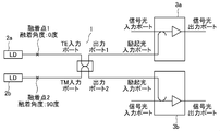
- FIG. 1A is a configuration diagram for explaining the light source device according to the first embodiment.
- FIG. 1B is a configuration diagram for explaining the optical amplifier according to the first embodiment.
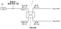
- 1C to 1E are explanatory diagrams for explaining the operation of the light source device according to the first embodiment.
- the light source device of FIG. 1A includes a laser diode (LD) 2a and a laser diode (LD) 2b as an example of a first light source and a second light source that output excitation light, an input port 1, an input port 2, an output port 1, and A polarization beam combiner (PBC) 1 that includes an output port 2 and that receives the pump light from the LDs 2a and 2b and is input to the input port 1 and the input port 2 to be multiplexed and demultiplexed.
- LD laser diode
- LD laser diode
- PBC polarization beam combiner
- the PBC 1 multiplexes or demultiplexes the pump light emitted from the LD 2a and the pump light emitted from the LD 2b, and then distributes the pump light to a plurality of rare earth-doped fibers of a fiber optical amplifier described later.
- the optical amplifier of FIG. 1B shows a more specific configuration using the light source device of FIG. 1A.
- the optical amplifier of FIG. 1B includes a light source device of FIG. 1A, a first optical amplifying unit that amplifies an optical signal using the pump light from the output port 1 and the pump light from the output port 2 of the PBC 1 of the light source device, and a second optical amplifying unit.
- An erbium-doped fiber optical amplifier (EDFA) 3a and an erbium-doped fiber optical amplifier (EDFA) 3b are included as examples of the optical amplifier.
- the input port 1 of the PBC 1 in FIG. 1A is a TE (Transverse Electric Wave) input port
- the input port 2 of the PBC 1 in FIG. 1A is a TM (Transverse Magnetic Wave) input port.
- the output fibers of the LDs 2a and 2b and the fibers of the TE input port and the TM input port of the PBC 1 are both polarization maintaining fibers.
- the fiber fusion angle at the fusion point 1 between the LD2a and the TE input port of the PBC1 at the fusion point 1 is 0 degree
- the output fiber of the LD 2a and the fiber of the TE input port of the PBC 1 are fused at the fusion point 1, and the angle formed by the slow axis of the fusion spliced fiber is 0 degree.
- the output fiber of the LD 2b and the fiber of the TM input port of the PBC 1 are fused at the fusion point 2, and the angle of the slow axis of the fusion spliced fiber is 90 degrees.
- the PBC 1 has a coupling portion 1a having a structure in which two fiber cores are brought close to each other, as shown in FIGS. 1C and 1D, thereby combining pump light input to the TE input port and the TM input port. Perform waves and split waves.
- the ratio of the intensity of the excitation light emitted from the two output ports of the PBC 1 can be changed by designing the coupling unit 1a. Specifically, the distance between adjacent cores at the coupling portion 1a, the length of the section at the coupling portion 1a, the refractive index and cross-sectional size of the core of the coupling portion 1a, the refractive index of the cladding of the coupling portion 1a, and the like. Design as design parameters.
- the EDFA 3a and the EDFA 3b each receive excitation light from the light source device into the excitation light input port, amplify the signal light to the signal light input port, and output the amplified signal light from the signal light output port.
- the operation of the optical amplifier and light source device of FIG. 1B will be described with reference to FIGS. 1C, 1D, and 1E.
- the pumping lights emitted from the LDs 2a and 2b are input to the input ports 1 and 2 of the PBC 1, multiplexed and demultiplexed, and then input to the respective pumping light input ports of the EDFAs 3a and 3b.
- the optical signals input to the respective signal light input ports of the EDFAs 3a and 3b are amplified by the power of the pump light inside the EDFAs 3a and 3b, and output from the signal light output ports.
- the excitation light beams having different light intensities can be made incident on the EDFAs 3a and 3b of the optical amplifier of FIG. 1B.
- pump lights having different light intensities can be made incident on the EDFAs 3a and 3b of the optical amplifier of FIG. 1B. Therefore, in an optical amplifier having a configuration including a plurality of EDFAs, pump lights having an optimum intensity are respectively made to enter. be able to.
- the pump light emitted from the output port 1 and the output port 2 includes the same light intensity from the LD 2a and the LD 2b.
- the attenuation ratio of the pump light incident on the EDFA 3a and EDFA 3b in FIG. 1B is equal.
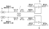
- FIG. 2A is a configuration diagram illustrating a light source device and an optical amplifier according to a second embodiment.
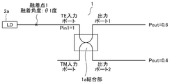
- 2B to 2D are explanatory diagrams for explaining the operation of the light source device according to the second embodiment.
- the second embodiment is a modification of the first embodiment and is based on the light source device shown in FIG. 1A.
- the same elements as those in the first embodiment are denoted by the same reference numerals, and detailed description thereof will be omitted.
- the optical amplifier of FIG. 2A includes a light source device similar to the light source device of FIG. 1A. That is, the light source device of FIG. 2A includes a laser diode (LD) 2a and a laser diode (LD) 2b as an example of a first light source and a second light source that output excitation light, a TE input port, a TM input port, and an output port 1.
- LD laser diode
- LD laser diode
- LD laser diode
- LD laser diode
- LD laser diode
- LD laser diode
- LD laser diode
- LD laser diode
- LD laser diode
- LD laser diode
- LD laser diode
- a polarization beam combiner (PBC) 1 that includes the pumping light from the LDs 2a and 2b and is input to a TE power port and a TM input port for multiplexing and demultiplexing.
- the PBC 1 multiplexes or demultiplexes the pump light emitted from the LD 2a and the pump light emitted from the LD 2b, and then distributes the pump light to a plurality of rare earth-doped fibers of the fiber optical amplifier.
- the optical amplifier of FIG. 2A further includes a first optical amplifier and a second optical amplifier that amplify an optical signal using pump light from the output port 1 and the output port 2 of the PBC 1 of the light source device similar to the optical amplifier of FIG. 1B.
- An erbium-doped fiber optical amplifier (EDFA) 3a and an erbium-doped fiber optical amplifier (EDFA) 3b are included as examples of the amplifier.
- the output fibers of the LDs 2a and 2b and the fibers of the TE input port and the TM input port of the PBC 1 are both polarization maintaining fibers.
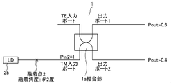
- the fiber fusion angle at the fusion point 1 between the LD 2a and the TE input port of the PBC 1 is 0 °, ⁇ 1 (degree) different from 90 °, and the TM input port of the LD 2b and the PBC 1 is used.
- the fiber fusion angle at the fusion point 2 is 0 ° and ⁇ 2 (degree) different from 90 °.
- the output fiber of the LD 2a and the fiber of the TE input port of the PBC 1 are fused at the fusion point 1, and the angle formed by the slow axis of the fusion spliced fiber is ⁇ 1 (degree).
- the output fiber of the LD 2b and the fiber of the TM input port of the PBC 1 are fused at the fusion point 2, and the angle formed by the slow axis of the fusion spliced fiber is ⁇ 2 (degree).
- the fiber fusion angle ⁇ 1 at the fusion point 1 between the LD 2a and the TE input port of the PBC1 is different from the fiber fusion angle ⁇ 2 at the fusion point 2 between the LD 2b and the TM input port of the PBC1.
- the PBC 1 has a coupling section 1a having a structure in which the cores of two fibers are brought close to each other as shown in FIG. 2B and FIG. 2C, thereby combining the pump light input to the TE input port and the TM input port. Perform waves and split waves.
- the ratio of the intensity of the excitation light emitted from the two output ports of the PBC 1 can be changed by designing the coupling unit 1a. Specifically, the distance between adjacent cores at the coupling portion 1a, the length of the section at the coupling portion 1a, the refractive index and the cross-sectional size of the core of the coupling portion 1a, the refractive index of the cladding of the coupling portion 1a, and the like. Design as design parameters.
- the EDFA 3a and the EDFA 3b each receive excitation light from the light source device into the excitation light input port, amplify the signal light to the signal light input port, and output the amplified signal light from the signal light output port.
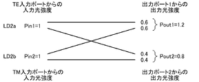
- the operation of the optical amplifier and the light source device of FIG. 2A will be described with reference to FIGS. 2B, 2C, and 2D.
- the pumping lights emitted from the LDs 2a and 2b are input to the input ports 1 and 2 of the PBC 1, multiplexed and demultiplexed, and then input to the respective pumping light input ports of the EDFAs 3a and 3b.
- the optical signals input to the respective signal light input ports of the EDFAs 3a and 3b are amplified by the power of the pump light inside the EDFAs 3a and 3b, and output from the signal light output ports.
- excitation lights having different light intensities can be incident on the EDFAs 3a and 3b of the optical amplifier of FIG. 2A.
- pump lights having different light intensities can be made incident on the EDFAs 3a and 3b of the optical amplifier of FIG. 2A. Therefore, in an optical amplifier having a configuration including a plurality of EDFAs, pump lights having optimum intensities are made incident. be able to.
- the pump light emitted from the output port 1 and the output port 2 includes the same light intensity from the LD 2a and the LD 2b.
- the attenuation ratio of the pump light incident on the EDFA 3a and EDFA 3b in FIG. 2A is equal.
- the ratio of the pump light power emitted from the two output ports of the PBC1 can be changed by designing the coupling part 1a of the PBC1, but not only that, but also the TE port of the PBC1, It can also be changed by the fiber fusion angle for each TM port. That is, the fiber fusion angle ⁇ 1 at the fusion point 1 between the LD2a and the TE input port of the PBC1 at the fusion point 1 and the fiber fusion angle ⁇ 2 at the fusion point 2 between the LD2b and the TM input port of the PBC1 can be optimally designed. For example, the same operation as the first embodiment can be realized.
- the pump light emitted from the output port 1 and the output port 2 includes the same light intensity from the LD 2a and the LD 2b.
- the attenuation ratio of the pump light incident on the EDFA 3a and EDFA 3b in FIG. 2A is equal.
- the ratio of the intensity of the pump light emitted from the two output ports of the PBC 1 depends not only on the design of the coupling portion 1a of the PBC 1 but also on the design of the fiber fusion angle for each of the TE input port and the TM input port. , The ratio can be varied.
- the fiber fusion angle for each of the TE input port and the TM input port pump lights having different light intensities can be made incident on the EDFAs 3a and 3b of the optical amplifier of FIG. 2B. In each of the optical amplifiers described above, the excitation light having the optimum intensity can be incident.
- the ratio of the excitation light intensity is changed by designing the fiber fusion angle with respect to each of the TE input port and the TM input port while using the PBC1 that is already commercially available, and the optical amplifier of FIG. Excitation lights having different light intensities can be incident on the EDFAs 3a and 3b.
- the output port of the polarization beam combiner is directly connected to the excitation light input port of the erbium-doped fiber optical amplifier (EDFA). It is not limited to this configuration. The same effect can be obtained not only when the output port is directly connected but also when, for example, the output port of the PBC is connected to a branch coupler and the output of the branch coupler is connected to a plurality of EDFAs.
- an erbium-doped fiber optical amplifier was used as the rare earth-doped fiber optical amplifier, but other elements of rare earth were added, for example, praseodymium ( Similar effects can be expected with other types of fiber-type optical amplifiers to which Pr), thulium (Tm), or ytterbium (Yb) is added.
Landscapes
- Physics & Mathematics (AREA)
- Electromagnetism (AREA)
- Optics & Photonics (AREA)
- Engineering & Computer Science (AREA)
- Plasma & Fusion (AREA)
- General Physics & Mathematics (AREA)
- Computer Networks & Wireless Communication (AREA)
- Signal Processing (AREA)
- Lasers (AREA)
Abstract
Description
初めに、第1実施形態による光源装置、及び光増幅器について、説明する。図1Aは、第1実施形態による光源装置を説明するための構成図である。図1Bは、第1実施形態による光増幅器を説明するための構成図である。図1C乃至図1Eは、第1実施形態による光源装置の動作を説明するための説明図である。
図1Aの光源装置は、励起光を出力する第1光源及び第2光源の一例としてのレーザーダイオード(LD)2a及びレーザーダイオード(LD)2bと、入力ポート1、入力ポート2、出力ポート1及び出力ポート2を含み、上記LD2a及びLD2bからの上記励起光が入力ポート1及び入力ポート2に入力されて合波分波する偏波ビームコンバイナー(PBC)1と、を含む。PBC1は、LD2aから出射された励起光とLD2bから出射された励起光との合波や分波を行った後、後述するファイバー型光増幅器の複数の希土類添加ファイバーへ励起光を分配する。
図1Bの光増幅器、光源装置の動作について、図1C、図1D及び図1Eを参照して説明する。LD2a、LD2bから出射された励起光は、PBC1の入力ポート1及び入力ポート2に入力され、合波、分波されたのち、EDFA3a、EDFA3bのそれぞれの励起光入力ポートに入力される。一方、EDFA3a、EDFA3bのそれぞれの信号光入力ポートに入力された光信号は、EDFA3a、EDFA3bの内部において励起光のパワーにより増幅されて、信号光出力ポートからそれぞれ出力される。
こうして本実施形態の光源装置では、図1Bの光増幅器のEDFA3a、EDFA3bにお互いに異なる光強度の励起光を入射することができる。このように図1Bの光増幅器のEDFA3a、EDFA3bにお互いに異なる光強度の励起光を入射することができるので、複数のEDFAを含む構成の光増幅器において、それぞれ最適な強度の励起光を入射することができる。
次に、第2実施形態による光源装置、及び光増幅器について、説明する。図2Aは、第2実施形態による光源装置、及び光増幅器を説明するための構成図である。図2B乃至図2Dは、第2実施形態による光源装置の動作を説明するための説明図である。第2実施形態は、第1実施形態の変形例であり、図1Aに示される光源装置を基礎とするものとする。第1実施形態と同様な要素に対しては同じ参照番号を付して、その詳細な説明を省略することとする。
図2Aの光増幅器は、図1Aの光源装置と同様な光源装置を含む。すなわち図2Aの光源装置は、励起光を出力する第1光源及び第2光源の一例としてのレーザーダイオード(LD)2a及びレーザーダイオード(LD)2bと、TE入力ポート、TM入力ポート、出力ポート1及び出力ポート2を含み、上記LD2a及びLD2bからの上記励起光がTE力ポート及びTM入力ポートに入力されて合波分波する偏波ビームコンバイナー(PBC)1と、を含む。PBC1は、LD2aから出射された励起光とLD2bから出射された励起光との合波や分波を行った後、ファイバー型光増幅器の複数の希土類添加ファイバーへ励起光を分配する。
図2Aの光増幅器、光源装置の動作について、図2B、図2C及び図2Dを参照して説明する。LD2a、LD2bから出射された励起光は、PBC1の入力ポート1及び入力ポート2に入力され、合波、分波されたのち、EDFA3a、EDFA3bのそれぞれの励起光入力ポートに入力される。一方、EDFA3a、EDFA3bのそれぞれの信号光入力ポートに入力された光信号は、EDFA3a、EDFA3bの内部において励起光のパワーにより増幅されて、信号光出力ポートからそれぞれ出力される。
こうして本実施形態の光源装置では第1実施形態と同様に、図2Aの光増幅器のEDFA3a、EDFA3bにお互いに異なる光強度の励起光を入射することができる。このように図2Aの光増幅器のEDFA3a、EDFA3bにお互いに異なる光強度の励起光を入射することができるので、複数のEDFAを含む構成の光増幅器において、それぞれ最適な強度の励起光を入射することができる。
以上好ましい実施形態について説明したが、本発明はこれらの実施形態に限られるものではなく、様々な変更が可能である。第1実施形態及び第2実施形態においては、偏波ビームコンバイナー(PBC)の出力ポートが、エルビウムドープファイバー型光増幅部(EDFA)の励起光入力ポートに直接接続されていたが、本発明はこの構成に限られない。直接接続されている場合に限らず、例えば、PBCの出力ポートが分岐カップラーに接続され、その分岐カップラーの出力が複数のEDFAに接続されている場合でも、同様の効果が得られる。
1a 結合部
2a、2b レーザーダイオード
3a、3b エルビウムドープファイバー型光増幅部
Claims (6)
- 励起光を出力する第1光源及び第2光源と、第1入力ポート、第2入力ポート、第1出力ポート及び第2出力ポートを含み、前記第1光源及び前記第2光源からの前記励起光が前記第1入力ポート及び前記第2入力ポートに入力されて合波分波する偏波ビームコンバイナーと、を含む光源装置。
- 前記偏波ビームコンバイナーの前記第1入力ポートはTE入力ポートであり、前記第2入力ポートはTM入力ポートである、請求項1に記載の光源装置。
- 前記第1光源の出力ファイバーと、前記偏波ビームコンバイナーの前記TE入力ポートとが融着接続されており、融着接続されたファイバーのスロー軸のなす角度が略0度であり、
前記第2光源の出力ファイバーと、前記偏波ビームコンバイナーの前記TM入力ポートとが融着接続されており、融着接続されたファイバーのスロー軸のなす角度が略90度である、請求項2に記載の光源装置。 - 前記第1光源の出力ファイバーと、前記偏波ビームコンバイナーの前記TE入力ポートとが融着接続されており、融着接続されたファイバーのスロー軸のなす角度がθ1度であり、
前記第2光源の出力ファイバーと、前記偏波ビームコンバイナーの前記TM入力ポートとが融着接続されており、融着接続されたファイバーのスロー軸のなす角度がθ2度である、請求項2に記載の光源装置。 - 前記θ1度は0度とは異なる角度であり、前記θ2度は90度とは異なる角度である、請求項4に記載の光源装置。
- 請求項1乃至請求項5のいずれか一項に記載の光源装置と、前記偏波ビームコンバイナーの前記第1出力ポート及び前記第2出力ポートからの前記励起光を用いて光信号を増幅する第1光増幅部及び第2光増幅部と、を含む光増幅器。
Priority Applications (4)
| Application Number | Priority Date | Filing Date | Title |
|---|---|---|---|
| JP2020527458A JP7081664B2 (ja) | 2018-06-28 | 2019-06-20 | 光源装置、及び光増幅器 |
| CN201980042784.5A CN112313844A (zh) | 2018-06-28 | 2019-06-20 | 光源设备和光学放大器 |
| EP19825590.3A EP3817161A4 (en) | 2018-06-28 | 2019-06-20 | LIGHT SOURCE DEVICE AND OPTICAL AMPLIFIER |
| US17/255,947 US20210249834A1 (en) | 2018-06-28 | 2019-06-20 | Light source device and optical amplifier |
Applications Claiming Priority (2)
| Application Number | Priority Date | Filing Date | Title |
|---|---|---|---|
| JP2018122973 | 2018-06-28 | ||
| JP2018-122973 | 2018-06-28 |
Publications (1)
| Publication Number | Publication Date |
|---|---|
| WO2020004224A1 true WO2020004224A1 (ja) | 2020-01-02 |
Family
ID=68984973
Family Applications (1)
| Application Number | Title | Priority Date | Filing Date |
|---|---|---|---|
| PCT/JP2019/024511 Ceased WO2020004224A1 (ja) | 2018-06-28 | 2019-06-20 | 光源装置、及び光増幅器 |
Country Status (5)
| Country | Link |
|---|---|
| US (1) | US20210249834A1 (ja) |
| EP (1) | EP3817161A4 (ja) |
| JP (1) | JP7081664B2 (ja) |
| CN (1) | CN112313844A (ja) |
| WO (1) | WO2020004224A1 (ja) |
Citations (8)
| Publication number | Priority date | Publication date | Assignee | Title |
|---|---|---|---|---|
| JPH05136495A (ja) * | 1991-11-08 | 1993-06-01 | Mitsubishi Electric Corp | フアイバ形光増幅器 |
| JPH08304860A (ja) | 1995-05-11 | 1996-11-22 | Kokusai Denshin Denwa Co Ltd <Kdd> | 光ファイバ増幅器 |
| JP2002116014A (ja) * | 2000-10-10 | 2002-04-19 | Furukawa Electric Co Ltd:The | 偏波面保存光ファイバにおける応力付与部の位置検出方法及び位置調整方法 |
| US20020181859A1 (en) * | 2001-05-29 | 2002-12-05 | Thomas Clark | Shared forward pumping in optical communications network |
| JP2004104473A (ja) | 2002-09-10 | 2004-04-02 | Mitsubishi Electric Corp | 光増幅中継器 |
| JP2013004667A (ja) | 2011-06-15 | 2013-01-07 | Nec Corp | 励起光出力装置および励起光出力制御方法 |
| JP2014006298A (ja) | 2012-06-21 | 2014-01-16 | Nippon Telegr & Teleph Corp <Ntt> | 光回路および光増幅器用励起光源 |
| JP2018122973A (ja) | 2017-02-01 | 2018-08-09 | 株式会社豊田自動織機 | フォークリフト |
Family Cites Families (6)
| Publication number | Priority date | Publication date | Assignee | Title |
|---|---|---|---|---|
| DE69228393T2 (de) * | 1991-11-08 | 1999-06-17 | Mitsubishi Denki K.K., Tokio/Tokyo | Faseroptischer Verstärker |
| JP3284507B2 (ja) * | 1993-06-28 | 2002-05-20 | 富士通株式会社 | 光通信システム用の光送信装置及び光増幅装置 |
| US6603593B2 (en) * | 2001-03-13 | 2003-08-05 | Jds Uniphase Corporation | Optical transmission link including raman amplifier |
| JP5662375B2 (ja) * | 2012-04-27 | 2015-01-28 | 日本電信電話株式会社 | 光回路および光増幅器用励起光源 |
| CN102684048B (zh) * | 2012-05-10 | 2014-04-09 | 清华大学 | 基于并联结构的超荧光光纤光源 |
| EP3613112B1 (en) * | 2017-04-20 | 2025-07-23 | Nec Corporation | Optical amplifying apparatus and method of amplifying optical signal |
-
2019
- 2019-06-20 EP EP19825590.3A patent/EP3817161A4/en not_active Withdrawn
- 2019-06-20 CN CN201980042784.5A patent/CN112313844A/zh active Pending
- 2019-06-20 JP JP2020527458A patent/JP7081664B2/ja active Active
- 2019-06-20 WO PCT/JP2019/024511 patent/WO2020004224A1/ja not_active Ceased
- 2019-06-20 US US17/255,947 patent/US20210249834A1/en not_active Abandoned
Patent Citations (8)
| Publication number | Priority date | Publication date | Assignee | Title |
|---|---|---|---|---|
| JPH05136495A (ja) * | 1991-11-08 | 1993-06-01 | Mitsubishi Electric Corp | フアイバ形光増幅器 |
| JPH08304860A (ja) | 1995-05-11 | 1996-11-22 | Kokusai Denshin Denwa Co Ltd <Kdd> | 光ファイバ増幅器 |
| JP2002116014A (ja) * | 2000-10-10 | 2002-04-19 | Furukawa Electric Co Ltd:The | 偏波面保存光ファイバにおける応力付与部の位置検出方法及び位置調整方法 |
| US20020181859A1 (en) * | 2001-05-29 | 2002-12-05 | Thomas Clark | Shared forward pumping in optical communications network |
| JP2004104473A (ja) | 2002-09-10 | 2004-04-02 | Mitsubishi Electric Corp | 光増幅中継器 |
| JP2013004667A (ja) | 2011-06-15 | 2013-01-07 | Nec Corp | 励起光出力装置および励起光出力制御方法 |
| JP2014006298A (ja) | 2012-06-21 | 2014-01-16 | Nippon Telegr & Teleph Corp <Ntt> | 光回路および光増幅器用励起光源 |
| JP2018122973A (ja) | 2017-02-01 | 2018-08-09 | 株式会社豊田自動織機 | フォークリフト |
Also Published As
| Publication number | Publication date |
|---|---|
| EP3817161A1 (en) | 2021-05-05 |
| JPWO2020004224A1 (ja) | 2021-07-08 |
| CN112313844A (zh) | 2021-02-02 |
| EP3817161A4 (en) | 2021-09-01 |
| US20210249834A1 (en) | 2021-08-12 |
| JP7081664B2 (ja) | 2022-06-07 |
Similar Documents
| Publication | Publication Date | Title |
|---|---|---|
| US11509110B2 (en) | Broadband Ho-doped optical fiber amplifier | |
| US5808786A (en) | Optical fiber amplifying device and method therefor | |
| JP7732535B2 (ja) | 光増幅装置および光増幅方法 | |
| US20160192043A1 (en) | Switchable optical amplifier and optical transmission apparatus | |
| JP2015167158A (ja) | マルチコアファイバ増幅器 | |
| US9762020B1 (en) | Bi-directionally pumped polarization maintaining fiber amplifier | |
| US7848014B2 (en) | Erbium and Erbium/Ytterbium cladding pumped hybrid optical amplifier | |
| US8363309B2 (en) | Optical amplifier and method for suppressing polarization dependent gain of optical amplifier | |
| WO2018135621A1 (ja) | マルチコア光ファイバ増幅器およびマルチコア光ファイバ増幅媒体を用いた光増幅方法 | |
| US20220337025A1 (en) | Optical amplifier | |
| US9768581B2 (en) | Pump and signal combiner for high numerical aperture use | |
| US9322993B1 (en) | All pump combiner with cladless inputs | |
| CN109952686B (zh) | 光放大器 | |
| KR100474714B1 (ko) | 광대역 광섬유 증폭기 | |
| CN102130416B (zh) | 激光装置 | |
| KR20030022974A (ko) | 분산 보상된 광섬유 증폭기 | |
| EP1339178B1 (en) | Dispersion-compensated raman optical fiber amplifier | |
| JP7081664B2 (ja) | 光源装置、及び光増幅器 | |
| JP3570927B2 (ja) | ラマン増幅を用いた光ファイバ通信システム | |
| EP1087474A2 (en) | High power, multi-stage doped optical amplifier | |
| US9595803B2 (en) | Fat-fiber adapter for pump use | |
| JP2740676B2 (ja) | 光増幅伝送回路 | |
| JP7416226B2 (ja) | 光増幅装置および光増幅方法 | |
| WO2021059443A1 (ja) | 増幅用ファイバ及び光増幅器 | |
| US9362709B1 (en) | Optical fiber laser architecture with partitioned pump and signal coupling |
Legal Events
| Date | Code | Title | Description |
|---|---|---|---|
| 121 | Ep: the epo has been informed by wipo that ep was designated in this application |
Ref document number: 19825590 Country of ref document: EP Kind code of ref document: A1 |
|
| ENP | Entry into the national phase |
Ref document number: 2020527458 Country of ref document: JP Kind code of ref document: A |
|
| NENP | Non-entry into the national phase |
Ref country code: DE |
|
| WWE | Wipo information: entry into national phase |
Ref document number: 2019825590 Country of ref document: EP |
|
| ENP | Entry into the national phase |
Ref document number: 2019825590 Country of ref document: EP Effective date: 20210128 |