WO2020004233A1 - Appareil de cuisson chauffant - Google Patents
Appareil de cuisson chauffant Download PDFInfo
- Publication number
- WO2020004233A1 WO2020004233A1 PCT/JP2019/024578 JP2019024578W WO2020004233A1 WO 2020004233 A1 WO2020004233 A1 WO 2020004233A1 JP 2019024578 W JP2019024578 W JP 2019024578W WO 2020004233 A1 WO2020004233 A1 WO 2020004233A1
- Authority
- WO
- WIPO (PCT)
- Prior art keywords
- temperature
- unit
- heating
- top plate
- temperature detection
- Prior art date
- Legal status (The legal status is an assumption and is not a legal conclusion. Google has not performed a legal analysis and makes no representation as to the accuracy of the status listed.)
- Ceased
Links
Images





Classifications
-
- H—ELECTRICITY
- H05—ELECTRIC TECHNIQUES NOT OTHERWISE PROVIDED FOR
- H05B—ELECTRIC HEATING; ELECTRIC LIGHT SOURCES NOT OTHERWISE PROVIDED FOR; CIRCUIT ARRANGEMENTS FOR ELECTRIC LIGHT SOURCES, IN GENERAL
- H05B6/00—Heating by electric, magnetic or electromagnetic fields
- H05B6/02—Induction heating
- H05B6/10—Induction heating apparatus, other than furnaces, for specific applications
- H05B6/12—Cooking devices
Definitions
- the present disclosure relates to a cooking device, and more particularly to a cooking device having a function of detecting a temperature of an object to be heated.
- the heating power of a cooking device has been adjusted based on the temperature at the bottom of the pan.
- the temperature at the bottom of the pot is detected by a temperature detecting element arranged below the plate.
- a transmission delay of the detected temperature occurs. For example, when the temperature of the pan is lowered by putting foods into the pan, it takes time to return to the original temperature, and when the temperature is high, scorching may occur, and the heat control may become unstable.
- a temperature detection device that is detachable from the duct is disposed.
- the temperature detection device can communicate with the cooking device and detects the temperature of the object to be heated from above.
- the heating cooker of Patent Document 1 adjusts the installation position of the temperature detection device by using an infrared light emitting element mounted on the temperature detection element arranged above. Infrared light emitted from the infrared light emitting element is received by a plurality of communication units disposed below the plate of the cooking device. The position of the temperature detecting element is calculated from the difference in the amount of received light in each communication unit.
- the present disclosure provides a heating cooker that can increase the degree of freedom of the installation position of the temperature detection module.
- a heating cooker includes a top plate on which a container that stores a food is placed, a heating unit that heats the container, and a heating control unit that controls a heating output of the heating unit.
- the heating control unit controls the heating output according to the temperature distribution detected by the temperature detection unit
- the temperature detection unit has a plurality of temperature detection elements, each of which detects temperature information
- the heating cooker further includes a temperature distribution correction unit that corrects the temperature distribution detected by the temperature detection unit based on the temperature information of a plurality of specific portions on the top plate.
- FIG. 1 is a perspective view of a heating cooker according to an embodiment of the present disclosure.
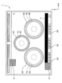
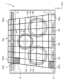
- FIG. 2 is a plan view of the cooking device.
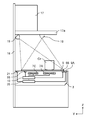
- FIG. 3 is a schematic diagram showing an installation state of the cooking device.
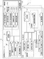
- FIG. 4 is a block diagram showing a control system of the cooking device.
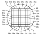
- FIG. 5 is an explanatory diagram illustrating a detection pixel area of the temperature sensor.
- FIG. 6 is a graph showing a change in the detected temperature according to the distance.
- FIG. 7 is an explanatory diagram illustrating a detection pixel area of the temperature detection unit installed right above.
- FIG. 8 is an explanatory diagram illustrating a detection pixel region of a temperature detection unit that is installed obliquely.
- FIG. 1 is a perspective view of a heating cooker according to an embodiment of the present disclosure.
- FIG. 2 is a plan view of the cooking device.
- FIG. 3 is a schematic diagram showing an installation state of the cooking device.
- FIG. 4 is a block diagram showing
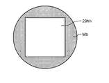
- FIG. 9 is an explanatory diagram illustrating the relationship between the size of the measurement target and the size of the detection pixel.
- FIG. 10 is an explanatory diagram illustrating the relationship between the size of the measurement target and the size of the detection pixel.
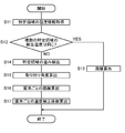
- FIG. 11 is a flowchart showing the flow of calculating the temperature correction coefficient.
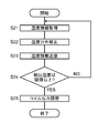
- FIG. 12 is a flowchart showing the flow of the temperature distribution correction.
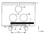
- FIG. 13 is an explanatory diagram illustrating an example of the arrangement of a part of the human body when positioning the temperature detection module.
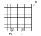
- FIG. 14 is an explanatory diagram illustrating an example of a thermal image when the distance between the temperature detection modules is long.
- FIG. 15 is an explanatory diagram illustrating an example of a thermal image when the distance between the temperature detection modules is short.
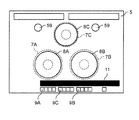
- FIG. 16 is an explanatory diagram illustrating an example of a top plate having a region where an object having a temperature different from the environmental temperature is placed.
- a heating cooker includes a top plate on which a container that stores a food is placed, a heating unit that heats the container, and a heating control unit that controls a heating output of the heating unit.
- a temperature detection module having a temperature detection unit that detects a temperature distribution on the top plate from above the top plate.
- the heating control unit controls the heating output according to the temperature distribution detected by the temperature detection unit, and the temperature detection unit includes a plurality of temperature detection elements each detecting temperature information.
- the cooking device further includes a temperature distribution correction unit that corrects the temperature distribution detected by the temperature detection unit based on the temperature information of a plurality of specific portions on the top plate.
- the plurality of temperature detecting elements may be arranged in an array (a state in which the temperature detecting elements are arranged in a vertical direction and a horizontal direction in plan view).
- the temperature distribution correction unit detects the temperature distribution of the plurality of specific portions at the same temperature based on a difference in the temperature information of the plurality of specific portions detected by the plurality of temperature detection elements. May be corrected.
- the temperature distribution correction unit detects a distortion in a detection area of each of the plurality of temperature detection elements based on a difference in the temperature information detected by the plurality of temperature detection elements, and detects the distortion from the detected distortion.
- the temperature distribution may be corrected.
- the cooking device further includes a temperature adjustment unit that heats or cools the specific portion of the top plate,
- the temperature distribution correction unit may correct the temperature distribution based on the temperatures of a plurality of specific portions of the heated or cooled top plate.
- the heating coil heats the plurality of specific portions of the top plate
- the temperature distribution correction section determines the temperature distribution based on temperature information of the plurality of specific portions of the heated top plate. May be corrected.
- the plurality of specific portions to be heated or cooled may be arranged outside a region of the heating unit (a region different from a region of the heating unit) in a plan view.
- the plurality of specific portions are a plurality of objects placed on the top plate and having a temperature different from an environmental temperature
- the temperature distribution detected by the temperature detector may be corrected based on the temperatures of the plurality of objects.
- the heating cooker may include a plurality of the heating units, and the plurality of specific portions may be the containers on the top plate that are heated by the plurality of heating units.
- the heating cooker further includes an operation unit connected to the heating control unit to set a heating amount, and the plurality of specific parts include a plurality of operation areas for a user to operate the operation unit. There may be.
- the temperature distribution correction unit includes a storage unit that calculates a temperature correction coefficient for each of the temperature detection elements from the distortion and stores the temperature correction coefficient, and the temperature distribution correction unit stores the temperature correction coefficient in the storage unit. The temperature distribution may be corrected using the obtained temperature correction coefficient.
- the temperature detection unit may increase a temperature detection gain when calculating the temperature correction coefficient.
- the heating unit may include a heating coil that generates an induction magnetic field to heat the container, and the heating control unit may supply the high-frequency current to the heating coil to heat the container. .
- FIG. 1 is a perspective view of a heating cooker 1 according to an embodiment of the present disclosure.
- FIG. 2 is a plan view of the cooking device 1 according to the embodiment.
- FIG. 3 is a schematic view showing an installation state of the heating cooker.
- FIG. 4 is a block diagram illustrating a control system of the heating cooker 1.
- the X-axis direction indicates the longitudinal direction (left-right direction) of the cooking device
- the Y-axis direction indicates the front-back direction
- the Z-axis direction indicates the height direction.
- the positive direction of the X-axis is rightward, and the negative direction is leftward.
- the cooking device 1 has a main body 3 and, as an upper portion of the main body 3, a top plate 5 on which the container Cr is placed.
- the container Cr contains, for example, an object Tc to be heated such as a stew, which is to be cooked.
- the heating cooker 1 is an induction heating cooker, and a heating coil as a heating unit of the heating cooker 1 is provided inside the main body 3 below the container mounting area on the top plate 5.
- 7A, 7B and 7C are arranged.
- Ring-shaped markers 8A, 8B, 8C indicating the container mounting area are printed on the top plate 5 above the corresponding heating coils 7A, 7B, 7C, respectively (see FIG. 2).
- the heating coils 7A to 7C generate an induction magnetic field to heat the container Cr.
- the coil control unit 10 as an example of the heating control unit supplies a high-frequency current to the heating coils 7A to 7C to heat the container Cr.
- the coil control unit 10 controls the amount of current from the heating coils 7A to 7C by controlling the amount of current flowing through the heating coils 7A to 7C.
- ring-shaped light-emitting portions 6A, 6B, and 6C are arranged on the top plate 5 outside each of the heating coils 7A, 7B, and 7C in plan view.
- the light emitting units 6A, 6B, 6C emit light, for example, when current is flowing through the corresponding heating coils 7A, 7B, 7C.
- Each of the light emitting units 6A to 6C has, for example, an LED (light emitting diode) light emitting substrate.
- a plurality of operation input units 9A, 9B, 9C are arranged on the front side of the top plate 5 of the cooking device 1 as operation units for the user to operate each of the heating coils 7A to 7C.
- the operation input units 9A to 9C may be, for example, touch keys or touch panels.
- the operation input unit 9A corresponds to the heating coil 7A
- the operation input unit 9B corresponds to the heating coil 7B
- the operation input unit 9C corresponds to the heating coil 7C.
- the operation input units 9A to 9C as operation units are connected to the coil control unit 10 as a heating control unit to set a heating amount.
- the coil control unit 10 controls start or stop of heating of the heating coil 7A.
- the coil control unit 10 adjusts the heating level of the heating coil 7A to, for example, four levels. The same applies to the functions of the other operation input units.
- the main body 3 includes a notifying unit 4 for notifying information regarding heating of the heating coils 7A to 7C.
- the notification unit 4 has a display unit 11 and a sound output unit 15 (see also FIG. 1).
- the display unit 11 is arranged on the front side of the top plate 5 of the cooking device 1, and displays the heating level of each of the heating coils 7A to 7C.
- the display unit 11 is, for example, a monochrome liquid crystal panel having a band shape extending in the longitudinal direction (left-right direction) of the top plate 5, but may be a color liquid crystal panel.
- the audio output unit 15 is arranged on the front side of the cooking device 1 and outputs audio guidance to the user.
- the audio output unit 15 is, for example, a speaker.
- the setting unit 13 is provided on the front side of the main body 3 of the cooking device 1.
- the setting unit 13 is connected to the control unit 25 and can be put into and taken out of the main body 3, and has a setting key 13a for setting the heating by the heating coils 7A to 7C in detail, the set contents and the heating coils 7A to 7C.
- a setting display section 13b for displaying a detailed state of 7C (see FIG. 1).
- the setting unit 13 sets the heating temperature, heating time, timer, and the like of the heating coils 7A to 7C.
- a range hood 17 is provided above the cooking device 1.
- the range hood 17 sucks air above the cooking device 1 into the inside through a hood portion 17a provided at a lower portion, and exhausts the air from a discharge port communicating with the outside.
- the cooking device 1 further includes a temperature detection module 19 that detects the temperature of the object Tc to be heated on the top plate 5 from above.
- the temperature detection module 19 is disposed at a position distant from the top plate 5, and is attached to and detached from, for example, a hood portion 17 a of the range hood 17 or a wall 18 (see FIG. 3) extending upward from the rear or side of the main body 3. Mounted as possible.
- the temperature detection module 19 is attached with a magnet, an adhesive, a clip, or the like.
- the temperature detection module 19 may be arranged on a ventilation fan, a duct, or a ceiling.
- the main body 3 has a first communication unit 21 and the temperature detection module 19 has a second communication unit 23 (see FIG. 4).
- the temperature information detected by the temperature detection module 19 is transmitted from the second communication unit 23 and received by the main body 3 by the first communication unit 21.
- the first communication unit 21 and the second communication unit 23 each have an antenna, and are wirelessly connected by wireless communication such as Wi-Fi (registered trademark), Bluetooth (registered trademark), or BLE (Bluetooth Low Energy). ing. Note that instead of including the first communication unit 21 and the second communication unit 23, the main body 3 and the temperature detection module 19 may be connected by wire.
- the cooking device 1 includes a control unit 25 and a storage unit 27 inside the main body 3.
- the control unit 25 is a processing device such as a CPU (Central Processing Unit) or a microprocessor, and is a storage unit such as a ROM (Read Only Memory), a RAM (Random Access Memory), a hard disk, or an SSD (Solid State Drive).
- ROM Read Only Memory
- RAM Random Access Memory
- SSD Solid State Drive
- the control unit 25 has a temperature information processing unit 25a.
- the temperature information processing section 25a determines the state of the target Tc based on the temperature information transmitted from the temperature detection module 19. Examples of the state of the object to be heated Tc include a normal state, a boiling state, a spilling precursor state, and a spilling state.
- the control unit 25 instructs the coil control unit 10 to stop heating control of the corresponding heating coil. Thereby, the coil control unit 10 can stop the heating from the corresponding heating coil among the heating coils 7A to 7C, and can prevent the occurrence of the spill.
- the temperature detection module 19 includes a temperature detection unit 29, a control unit 31, a storage unit 33, and a power storage unit 35.
- the temperature detection unit 29 includes a temperature sensor 29a that detects a temperature distribution on the top plate 5 within the visual field range from above, and an amplification unit 29b that amplifies a detection signal of the temperature sensor 29a.
- the temperature sensor 29a is, for example, an infrared sensor or a thermal imaging camera.
- the thermal image detected by the temperature detector 29 includes information on the temperature distribution on the top plate 5.
- the temperature sensor 29a can photograph the entire top plate 5 from above if it is set in an appropriate photographing direction.
- the distance from the temperature sensor 29a to the top plate 5 is, for example, not less than 600 mm and not more than 2000 mm.
- the temperature sensors 29a of the temperature detection unit 29 are a plurality of temperature detection elements arranged in an array (a plurality of elements are arranged in a vertical direction and a horizontal direction in a plan view). Of detection pixels.
- the temperature sensor 29a according to the embodiment is, for example, an array-type temperature sensor having 64 detection pixels 29aa to 29hh of 8 ⁇ 8.
- the control unit 31 is a processing device such as a CPU or a microprocessor, and performs various functions described below by executing programs stored in a storage unit 33 such as a ROM, a RAM, a hard disk, or an SSD. It is configured as follows.
- the control unit 31 includes an attachment determination unit 31a that determines whether the measurement direction of the temperature sensor 29a of the temperature detection unit 29 is perpendicular to the top plate 5, and a temperature distribution detected by the temperature detection unit 29.
- a temperature distribution correction unit 31b for correcting temperature information may be mounted on the main body 3 side.
- the power storage unit 35 supplies power to the temperature detection unit 29, the control unit 31, the storage unit 33, and the second communication unit 23, respectively.
- the power storage unit 35 is, for example, a battery.
- a region having a temperature higher or lower than the ambient temperature is formed on the top plate 5.
- a region having a temperature higher or lower than the environmental temperature is formed in a plurality of specific portions on the top plate 5, and the region of the specific portion is detected by the temperature detector 29. Since the positional relationship between the plurality of specific portions can be measured in advance, the temperature distribution correction unit 31b can calculate the mounting angle of the temperature detection unit 29 by a geometric operation.
- a temperature adjusting section 55 (connected to the coil control section 10) for heating or cooling a specific area 57 (see FIG. 2) as a specific portion on the top plate 5 is disposed below the top plate 5 ( (See FIG. 3).
- An example of the temperature adjusting unit 55 to be heated is an electric heater.
- As the temperature adjustment unit 55 for cooling for example, a Peltier element is used.
- the temperature adjusting unit 55 can generate a specific area 57 having a temperature different from the environmental temperature on the top plate 5 as shown in FIG.
- the temperature different from the environmental temperature in the specific area 57 is used for correcting the temperature distribution on the top plate 5 detected by the temperature detection unit 29.
- the temperature distribution correction unit 31b corrects the temperature distribution based on the temperature of the specific region 57 of the top plate 5 that has been heated or cooled.
- the plurality of specific regions 57 are provided apart from each other.
- the plurality of specific regions 57 are not limited to two, and may be three or more.
- the specific regions 57 may be provided at, for example, four corners of the top plate 5.
- the temperature adjusting section 55 is arranged outside the area of the heating coils 7A to 7C (an area different from the area of the heating coil) in plan view. Therefore, the area of the top plate 5 heated by the heating coils 7A to 7C does not overlap with the specific area 57 whose temperature is adjusted by the temperature adjusting unit 55.
- the specific region 57 as a specific portion to be heated or cooled is disposed outside the region of the heating coils 7A to 7C as the heating unit.
- the temperature of the specific region 57 can be appropriately detected by the temperature detection unit 29.
- the heating coils 7A to 7C serving as heating units may also serve the role of the temperature adjustment unit 55.
- the heating coils 7A to 7C heat a specific portion of the top plate 5, and the temperature distribution correction unit 31b may correct the temperature distribution based on the temperature of the specific portion of the heated top plate 5.
- Joule heat is generated by the resistance of the heating coils themselves, and the temperatures of the heating coils 7A to 7C rise.
- the heat propagates as radiant heat to the top plate 5, and the temperature of a specific portion of the top plate 5 above the heating coils 7A to 7C rises. In this way, the temperature of the specific portion on the top plate 5 becomes higher than the environmental temperature of the other portions.
- the temperature detecting section 29 the temperature may be used for correcting the temperature distribution on the top plate 5.
- the temperature sensor 29a detects the temperature by infrared rays, the detected temperature decreases as the distance from the temperature detection module 19 to the top plate 5 increases. Further, the detected temperature also differs depending on the angle between the temperature detection module 19 and the measurement target.
- FIG. 6 is a graph showing a change in the detected temperature with time according to the distance.
- a temperature curve TH detected by the detection pixel 29a is shown.
- the temperature of the temperature curve TL is the temperature Tp2
- the temperature of the temperature curve TH is the temperature Tp3.
- the relationship between the temperature Tp2 and the temperature Tp3 is Tp3 ⁇ Tp2 ⁇ 100. If the temperature sensor 29a is installed with an inclination angle, the distance between each detection pixel and the measurement target varies. As a result, the accuracy of the detected temperature varies for each detection pixel of the temperature sensor 29a.
- the detection temperature of the detection pixel whose distance to the measurement target is long is lower than the actual temperature.
- each of the detection pixels 29aa to 29hh of the temperature sensor 29a can uniformly detect the temperature of a region having the same area without distortion.
- FIG. 7 shows a region (viewing range) in which each of the detection pixels 29aa to 29hh detects a temperature.
- the temperature detection module 19 solid line
- the other detection pixel for example, the detection pixels 29aa and 29ha
- the detection pixels farther from the temperature detection module 19 for example, the detection pixels 29ah and 29hh
- the temperature detected by the temperature detection module 19 is the average temperature of the field of view detected by each of the detection pixels.
- the average temperature of the visual field range of the detection pixel 29hh is equal to the temperature of the measurement target Mb. No error occurs.
- the average temperature of the visual field range of the detection pixel 29hh is different from the temperature of the measurement target Mb. An error occurs. Note that when the specific area 57 is cooled, the concept of averaging when the measurement target is small is opposite to that when the specific area 57 is heated.
- the detection pixel that is far away from the measurement target has an error due to the long distance, and the detection area when the measurement target is viewed obliquely when installed on the wall 18.
- the temperature error is caused by both factors of the error (area) of the visual field range due to the distortion of the image. Therefore, it is desirable to determine whether it is installed on the wall 18 or directly above it, and make a correction according to the state.
- the attachment state of the temperature detection module 19 to the range hood 17 or the wall 18 is determined, and the temperature detection is performed according to the attached state.
- the temperature distribution detected by the unit 29 is corrected.
- the attachment determination unit 31a of the control unit 31 determines that there is no distortion in each detection pixel of the temperature sensor 29a if the detection temperatures of the plurality of specific regions 57 of the predetermined temperature on the top plate 5 are the same.
- the fact that the detected temperatures of the plurality of specific regions 57 are the same includes that each of the detected temperatures is within a predetermined temperature difference.
- the temperature distribution correction unit 31b corrects the temperature distribution detected by the temperature detection unit 29 based on the temperatures of the specific regions 57 as a plurality of specific portions on the top plate 5.
- the temperature distribution correction unit 31b includes a distortion detection unit 31ba, a mounting angle calculation unit 31bb, a distance calculation unit 31bc, and a temperature correction unit 31bd.
- the distortion detection unit 31ba detects distortion of the detection pixel of the temperature sensor 29a.
- the attachment angle calculation unit 31bb calculates the attachment angle of the temperature detection unit 29 from the distortion of the detection pixel.
- the distance calculation unit 31bc calculates the distance from the temperature sensor 29a to the measurement target area on the top plate 5 based on the mounting angle of the temperature detection unit 29.
- the temperature correction unit 31bd corrects the temperature distribution according to the calculated distance between the detection pixels of each temperature sensor 29a.
- the distortion detection unit 31ba detects distortion of each detection pixel of the temperature sensor 29a.
- the distortion rate of each detection pixel of the temperature sensor 29a is calculated from the difference between the set temperature of the plurality of specific regions 57 and the detected temperature.
- the attachment angle calculation unit 31bb calculates the attachment angle of the temperature detection unit 29 by a geometric calculation based on the distortion rate of each detection pixel of the temperature sensor 29a.
- the attachment angle is an angle from the perpendicular of the top plate 5.
- the distance calculation unit 31bc performs a geometric calculation based on the calculated attachment angle of the temperature detection unit 29 and detects the detection pixel 29aa of the temperature sensor 29a. The distance from to 29 hh to each measurement target area on the top plate 5 is calculated.
- the distance calculation unit 31bc determines the temperature sensor based on the difference between the set temperature of the specific area 57 and the detected temperature. The distance from 29a to the top plate 5 is calculated. The distance calculation unit 31bc further calculates a temperature correction coefficient for each of the detection pixels 29aa to 29hh according to the calculated distance. The calculated temperature correction coefficients are stored in the storage unit 33.
- the temperature correction unit 31bd corrects the temperature detected by the detection pixels 29aa to 29hh using the calculated temperature correction coefficients of the detection pixels 29aa to 29hh, thereby correcting the temperature distribution detected by the temperature detection unit 29. I do.
- the control unit 25 requests the temperature detection module 19 to acquire the temperature information.
- the control unit 25 controls the temperature of the specific area 57 to a predetermined temperature by the temperature adjustment unit 55.
- step S11 the temperature sensor 29a acquires a temperature distribution on the top plate 5. Thereby, the temperature information of the plurality of specific areas 57 can be obtained.
- step S12 the attachment determination unit 31a determines whether the detected temperatures of the plurality of specific regions 57 are the same. If the attachment determination unit 31a determines that the plurality of detected temperatures are the same (S12, YES), the distance calculation unit 31bc determines the temperature based on the difference between the set temperature of the specific area 57 and the detected temperature in step S13. The distance between the sensor 29a and the top plate 5 is calculated. A temperature correction coefficient of the temperature sensor 29a is calculated based on the calculated distance. The calculated temperature correction coefficient is stored in the storage unit 33.
- the distortion detection unit 31ba detects the temperature of the plurality of specific regions 57 in step S14. The distortion rate of the field of view of each detection pixel is detected.
- step S15 the attachment angle calculation unit 31bb calculates the attachment angle of the temperature detection unit 29 based on the distortion rate of the field of view of each detection pixel.
- step S16 the distance calculation unit 31bc calculates a distance from each detection pixel of the temperature sensor 29a to a corresponding detection area on the top plate 5 based on the calculated attachment angle.
- step S17 the distance calculation unit 31bc further calculates a temperature correction coefficient for correcting temperature information for each detection pixel based on the calculated distance to the detection area for each detection pixel.
- the calculated temperature correction coefficient is stored in the storage unit 33.
- control unit 25 sends the temperature information to the control unit 31 of the temperature detection module 19. Request acquisition.
- step S21 the temperature sensor 29a acquires a temperature distribution on the top plate 5 as temperature information.
- step S22 the acquired temperature information of each detection pixel is corrected by the temperature correction unit 31bd of the control unit 31 using the temperature correction coefficient stored in the storage unit 33. Thereby, the detected temperature distribution is corrected.
- step S23 the corrected information on the temperature distribution is transmitted from the second communication unit 23 to the first communication unit 21, and received by the temperature information processing unit 25a of the control unit 25.
- the temperature information processing unit 25a determines the state of the target Tc based on the received information on the temperature distribution.
- step S24 the temperature information processing unit 25a of the control unit 25 determines whether the absolute value of the detected temperature or the amount of change per unit time of the coil area corresponding to the area of each of the heating coils 7A to 7C in the information of the temperature distribution is: It is determined whether or not the value is equal to or greater than a predetermined threshold. For example, if the absolute value of the detected temperature TA of the coil region or the amount of change per unit time is less than the threshold value Tp1, the process returns to step S21 after the elapse of the detection cycle, as No in step S24.
- the temperature information processing unit 25a predicts that a spill will occur, and outputs prediction information of the spill to the coil control unit 10.
- the coil control unit 10 reduces the heating power of the corresponding heating coil based on the prediction information (S25). Note that a plurality of thresholds may be prepared and the heating power may be adjusted stepwise.
- the cooking device 1 of the embodiment includes the main body 3 and the temperature detection module 19.
- the main body 3 includes a top plate 5 on which a container Cr accommodating the object Tc to be heated, heating coils 7A to 7C for heating the container Cr, and a coil for controlling the heating output of the heating coils 7A to 7C.
- a control unit 10 10.
- the temperature detection module 19 includes a temperature detection unit 29 that detects a temperature distribution on the top plate 5 from above the top plate 5.
- the coil control unit 10 controls the heating output according to the temperature information detected by the temperature detection unit 29.
- the temperature detecting section 29 has a plurality of temperature detecting pixels 29aa to 29hh.
- the temperature detection module 19 includes a temperature distribution correction unit 31b that corrects the temperature distribution detected by the temperature detection unit 29 based on the temperatures of the plurality of specific regions 57 on the top plate 5.
- the degree of freedom of the installation position of the temperature detection module 19 can be increased.
- the temperature detection module 19 can be attached obliquely to the cooking device 1, so that dirt attached to the temperature detection unit 29 can be reduced. it can.
- the frequency of removing the stain on the temperature detection unit 29 can be reduced, and the burden on the user can be reduced.
- the temperature distribution correction unit 31b corrects the temperature distribution of the specific region 57 as the specific portion having the same temperature based on the difference in the temperature information detected by the detection pixels 29aa to 29hh. .
- the attachment state of the temperature detection module 19 can be determined from the difference in the temperature information detected by the plurality of detection pixels 29aa to 29hh. Thereby, the temperature distribution can be corrected according to the mounting state of the temperature detection module 19, and an appropriate temperature distribution can be obtained.
- the temperature distribution correction unit 31b detects distortion in the detection area of the plurality of detection pixels 29aa to 29hh based on the difference in the temperature information detected by the plurality of detection pixels 29aa to 29hh, and detects the distortion from the detected distortion. Correct the temperature distribution.
- the distortion of the detection area of the plurality of detection pixels 29aa to 29hh corresponds to the mounting angle of the temperature detection unit 29. Therefore, the temperature distribution can be corrected from the detected distortion according to the distance to the detection area of the plurality of detection pixels 29aa to 29hh.
- the temperature distribution correction unit 31b calculates a temperature correction coefficient for each temperature detection pixel from the distortion of the detection area of the detection pixel, and includes a storage unit 33 in which the temperature correction coefficient is stored. The temperature distribution is corrected using the temperature correction coefficient stored in. Thus, the calculation of the temperature correction coefficient may be performed when the temperature detection module 19 is installed on the wall 18.
- the temperature adjustment unit 55 instead of using the temperature adjustment unit 55 to set the specific area 57 to a temperature higher than the ambient temperature, the following configuration may be adopted. As shown in FIG. 13, for example, a user's finger is placed on the left end of the operation input unit 9 ⁇ / b> A on the top plate 5 and the right end of the operation input unit 9 ⁇ / b> B. To get. Since the finger is a part of the human body, the temperature is about 35 ° C. When the environmental temperature is, for example, 30 ° C., there is a temperature difference of 5 ° C., so that the finger detection area 29 can detect the finger area.
- the temperature detection unit 29 can detect the temperature of the operation area where the user operates the operation input units 9A and 9B as in the specific area 57. Therefore, an operation area in which the user operates the operation input units 9A and 9B as operation units can be set as the specific part instead of the specific area 57. If there is a difference between the temperatures detected at that time, it can be understood that the temperature detection module 19 is installed on a wall or the like.
- the temperature detection module 19 causes It is highly likely that it is installed on the left wall of the container 1. This is because the detected temperature when the right end of the operation input unit 9B is pressed is low, so the distance is long and the finger to be measured is smaller than the visual field range of the temperature detection module 19, This is because the temperature was averaged with the temperature of the top plate 5 other than the finger.
- FIG. 14 is an explanatory diagram illustrating an example of the acquired thermal image 51 when the installation position of the temperature detection module 19 is long relative to the top plate 5.
- the two pixel areas 51a of the thermal image 51 detect the temperature of the finger, and these pixel areas 51a correspond to the area of the finger. There is an area for two pixels between the two pixel areas 51a of the thermal image 51.
- the physical distance La between the left end of the operation input unit 9A on which the finger is placed and the right end of the operation input unit 9B is measured in advance and stored in the storage unit 33. Since the distance La on the top plate 5 (see FIG. 3) corresponds to the length of two pixels on the thermal image 51, the distance calculation unit 31bc of the temperature distribution correction unit 31b determines the visual field range of the temperature sensor 29a and The height from the top plate 5 can be detected.
- FIG. 15 is an explanatory diagram showing an example of the acquired thermal image 53 when the installation position of the temperature detection module 19 is short with respect to the top plate 5.
- Two pixel regions 53a of the thermal image 53 detect the temperature of the finger, and these pixel regions 53a correspond to the region of the finger. Between the two pixel regions 53a of the thermal image 53, there is a region for six pixels. Since the distance La on the top plate 5 corresponds to the length of six pixels on the thermal image 53, the distance calculation unit 31bc of the temperature distribution correction unit 31b determines the distance from the field of view of the temperature sensor 29a to the top plate 5. Can be calculated.
- the distance calculation unit 31bc of the temperature distribution correction unit 31b calculates the visual field range of the temperature detection module 19, so that the installation height of the temperature detection module 19 can be detected.
- the temperature correction unit 31bd corrects the temperature detected by the temperature detection unit 29 based on the distance from the top plate 5 calculated by the distance calculation unit 31bc. As a result, the burden on the user for measurement can be reduced, and more accurate heating control can be realized.
- the temperature detection unit 29 of the temperature detection module 19 may increase the temperature detection gain. Specifically, when acquiring the temperature information for calculating the temperature correction coefficient, the amplification of the amplifier 29b is increased. Thereby, even when the temperature difference between the environmental temperature and the plurality of specific portions on the top plate 5 is small, the plurality of specific portions can be accurately detected.
- the temperature adjusting section 55 instead of arranging the temperature adjusting section 55 on the main body 3 to change the temperature of the specific area 57, an object having a temperature different from the environmental temperature is placed on the top plate 5 and the temperature detecting section 29 detects the object.
- the temperature distribution may be corrected.
- a plurality of regions 59 on which an object having a temperature different from the environmental temperature is placed on the top plate 5 are provided apart from each other.
- the temperature detecting unit 29 can detect the area 59. Therefore, the temperature distribution correction unit 31b can correct the temperature distribution detected by the temperature detection unit 29 based on the temperature of the object placed in the area 59.
- two regions 59 are provided on the top plate 5 in FIG. 16, three or more regions 59 may be provided.
- the temperature distribution may be corrected by heating the container Cr on the plurality of heating coils 7A to 7C.
- the temperature detecting section 29 can detect the positions of these heated containers Cr.
- the temperature distribution correction unit 31b can correct the temperature distribution of the temperature detection unit 29 based on the temperature of the container Cr.
- the temperature distribution can be corrected. it can.
- Patent Literature 1 if there is an obstacle on the optical path of infrared light, the communication unit cannot receive infrared light, so that there is a problem that the position cannot be calculated.
- the present embodiment does not have such a problem because it does not include a communication unit that receives infrared light emitted from the infrared light emitting element.
- the heating cooker 1 is an induction heating cooker for induction heating the container Cr using the heating coils 7A to 7C, but is not limited thereto.
- the cooking device 1 may be a gas cooking device.
- the container Cr is placed on a container serving as a container placement portion provided on the top plate 5 of the main body 3, and is heated from below by a gas burner serving as a heating unit.
- a gas amount control unit is provided instead of the coil control unit.
- the gas amount control unit as an example of the heating control unit controls the gas amount supplied to the gas burner.
- the present disclosure it is possible to provide a heating cooker that can increase the degree of freedom of the installation position of the temperature detection module. Therefore, the present disclosure is applicable and useful for a heating cooker, particularly a heating cooker having a function of detecting the temperature of an object to be heated.
Landscapes
- Physics & Mathematics (AREA)
- Electromagnetism (AREA)
- Induction Heating Cooking Devices (AREA)
Abstract
L'invention concerne un appareil de cuisson chauffant pourvu : d'un corps principal ayant une plaque supérieure sur laquelle est placé un récipient contenant de la matière à cuire ; d'une unité de chauffage pour chauffer le récipient et d'une unité de commande de chauffage pour commander la sortie de chauffage de l'unité de chauffage ; et d'un module de détection de température pourvu d'une unité de détection de température pour détecter, depuis le haut de la plaque supérieure, la répartition de température de la plaque supérieure. L'unité de commande de chauffage commande la sortie de chauffage en fonction de la répartition de température détectée par l'unité de détection de température, et l'unité de détection de température comporte une pluralité d'éléments de détection de température, chacun d'eux détectant des informations de température. L'appareil de cuisson chauffant comprend en outre une unité de correction de répartition de température qui corrige la répartition de température détectée par l'unité de détection de température, sur la base des informations de température pour une pluralité de parties spécifiées sur la plaque supérieure.
Priority Applications (1)
| Application Number | Priority Date | Filing Date | Title |
|---|---|---|---|
| CN201980003783.XA CN111052860A (zh) | 2018-06-28 | 2019-06-20 | 加热烹调器 |
Applications Claiming Priority (2)
| Application Number | Priority Date | Filing Date | Title |
|---|---|---|---|
| JP2018-123614 | 2018-06-28 | ||
| JP2018123614A JP2020004621A (ja) | 2018-06-28 | 2018-06-28 | 加熱調理器 |
Publications (1)
| Publication Number | Publication Date |
|---|---|
| WO2020004233A1 true WO2020004233A1 (fr) | 2020-01-02 |
Family
ID=68984976
Family Applications (1)
| Application Number | Title | Priority Date | Filing Date |
|---|---|---|---|
| PCT/JP2019/024578 Ceased WO2020004233A1 (fr) | 2018-06-28 | 2019-06-20 | Appareil de cuisson chauffant |
Country Status (3)
| Country | Link |
|---|---|
| JP (1) | JP2020004621A (fr) |
| CN (1) | CN111052860A (fr) |
| WO (1) | WO2020004233A1 (fr) |
Families Citing this family (1)
| Publication number | Priority date | Publication date | Assignee | Title |
|---|---|---|---|---|
| CN119536399B (zh) * | 2024-10-28 | 2025-10-28 | 广东擎烽电气科技有限公司 | 一种用于烤箱的温度控制方法及装置 |
Citations (4)
| Publication number | Priority date | Publication date | Assignee | Title |
|---|---|---|---|---|
| JPH0960885A (ja) * | 1995-08-29 | 1997-03-04 | Sanyo Electric Co Ltd | 電子レンジ |
| JP2012220096A (ja) * | 2011-04-08 | 2012-11-12 | Panasonic Corp | レンジフードファン |
| JP2015106462A (ja) * | 2013-11-29 | 2015-06-08 | 日立アプライアンス株式会社 | 加熱調理器 |
| JP2017194449A (ja) * | 2016-04-15 | 2017-10-26 | パナソニックIpマネジメント株式会社 | 調理支援方法および調理支援システム |
Family Cites Families (3)
| Publication number | Priority date | Publication date | Assignee | Title |
|---|---|---|---|---|
| JP3654286B2 (ja) * | 2002-12-25 | 2005-06-02 | 松下電器産業株式会社 | 加熱調理器 |
| JP2012247074A (ja) * | 2011-05-25 | 2012-12-13 | Panasonic Corp | 加熱調理器 |
| JP6765064B2 (ja) * | 2016-06-23 | 2020-10-07 | パナソニックIpマネジメント株式会社 | 赤外線検出装置 |
-
2018
- 2018-06-28 JP JP2018123614A patent/JP2020004621A/ja active Pending
-
2019
- 2019-06-20 CN CN201980003783.XA patent/CN111052860A/zh active Pending
- 2019-06-20 WO PCT/JP2019/024578 patent/WO2020004233A1/fr not_active Ceased
Patent Citations (4)
| Publication number | Priority date | Publication date | Assignee | Title |
|---|---|---|---|---|
| JPH0960885A (ja) * | 1995-08-29 | 1997-03-04 | Sanyo Electric Co Ltd | 電子レンジ |
| JP2012220096A (ja) * | 2011-04-08 | 2012-11-12 | Panasonic Corp | レンジフードファン |
| JP2015106462A (ja) * | 2013-11-29 | 2015-06-08 | 日立アプライアンス株式会社 | 加熱調理器 |
| JP2017194449A (ja) * | 2016-04-15 | 2017-10-26 | パナソニックIpマネジメント株式会社 | 調理支援方法および調理支援システム |
Also Published As
| Publication number | Publication date |
|---|---|
| JP2020004621A (ja) | 2020-01-09 |
| CN111052860A (zh) | 2020-04-21 |
Similar Documents
| Publication | Publication Date | Title |
|---|---|---|
| US9414443B2 (en) | Induction heating device | |
| JP2002075624A (ja) | 誘導加熱調理器 | |
| CN111034356A (zh) | 加热烹调系统、报知加热烹调器中使用的温度检测部的设置状态的方法、以及调整加热烹调器中使用的温度检测部的设置状态的方法 | |
| JP2015106462A (ja) | 加熱調理器 | |
| WO2019202951A1 (fr) | Système de cuisson chauffant, et procédé de notification d'état d'installation de caméra pour capturer une image d'un appareil de cuisson chauffant | |
| WO2020004233A1 (fr) | Appareil de cuisson chauffant | |
| JP3903883B2 (ja) | 誘導加熱調理器 | |
| JP2010251130A (ja) | 誘導加熱調理器 | |
| JP4023293B2 (ja) | 誘導加熱調理器 | |
| JP2009176751A (ja) | 誘導加熱調理器 | |
| JP7142321B2 (ja) | 加熱調理器 | |
| JP4120696B2 (ja) | 誘導加熱調理器 | |
| JP5209383B2 (ja) | 誘導加熱調理器 | |
| JP7316830B2 (ja) | 誘導加熱調理器 | |
| JP5209399B2 (ja) | 誘導加熱調理器 | |
| JP6150702B2 (ja) | 加熱調理器 | |
| JP7617557B2 (ja) | 加熱調理器 | |
| JP2006344456A (ja) | 誘導加熱調理器 | |
| JP7591749B2 (ja) | 加熱調理器 | |
| JP2010170784A (ja) | 加熱調理器 | |
| JP5084785B2 (ja) | 加熱調理器 | |
| JP3997891B2 (ja) | 誘導加熱調理器 | |
| JP4301063B2 (ja) | 多口加熱調理器 | |
| JP5051162B2 (ja) | 誘導加熱調理器 | |
| JP5865010B2 (ja) | 誘導加熱調理器 |
Legal Events
| Date | Code | Title | Description |
|---|---|---|---|
| 121 | Ep: the epo has been informed by wipo that ep was designated in this application |
Ref document number: 19825957 Country of ref document: EP Kind code of ref document: A1 |
|
| NENP | Non-entry into the national phase |
Ref country code: DE |
|
| 122 | Ep: pct application non-entry in european phase |
Ref document number: 19825957 Country of ref document: EP Kind code of ref document: A1 |