WO2020004373A1 - 貫通孔付工具、ダイヤモンド部品、及び、ダイヤモンド素材 - Google Patents
貫通孔付工具、ダイヤモンド部品、及び、ダイヤモンド素材 Download PDFInfo
- Publication number
- WO2020004373A1 WO2020004373A1 PCT/JP2019/025108 JP2019025108W WO2020004373A1 WO 2020004373 A1 WO2020004373 A1 WO 2020004373A1 JP 2019025108 W JP2019025108 W JP 2019025108W WO 2020004373 A1 WO2020004373 A1 WO 2020004373A1
- Authority
- WO
- WIPO (PCT)
- Prior art keywords
- diamond
- hole
- tool
- single crystal
- component
- Prior art date
- Legal status (The legal status is an assumption and is not a legal conclusion. Google has not performed a legal analysis and makes no representation as to the accuracy of the status listed.)
- Ceased
Links
Images


Classifications
-
- B—PERFORMING OPERATIONS; TRANSPORTING
- B21—MECHANICAL METAL-WORKING WITHOUT ESSENTIALLY REMOVING MATERIAL; PUNCHING METAL
- B21C—MANUFACTURE OF METAL SHEETS, WIRE, RODS, TUBES, PROFILES OR LIKE SEMI-MANUFACTURED PRODUCTS OTHERWISE THAN BY ROLLING; AUXILIARY OPERATIONS USED IN CONNECTION WITH METAL-WORKING WITHOUT ESSENTIALLY REMOVING MATERIAL
- B21C3/00—Profiling tools for metal drawing; Combinations of dies and mandrels for metal drawing
- B21C3/02—Dies; Selection of material therefor; Cleaning thereof
- B21C3/025—Dies; Selection of material therefor; Cleaning thereof comprising diamond parts
-
- C—CHEMISTRY; METALLURGY
- C01—INORGANIC CHEMISTRY
- C01B—NON-METALLIC ELEMENTS; COMPOUNDS THEREOF; METALLOIDS OR COMPOUNDS THEREOF NOT COVERED BY SUBCLASS C01C
- C01B32/00—Carbon; Compounds thereof
- C01B32/25—Diamond
-
- C—CHEMISTRY; METALLURGY
- C01—INORGANIC CHEMISTRY
- C01B—NON-METALLIC ELEMENTS; COMPOUNDS THEREOF; METALLOIDS OR COMPOUNDS THEREOF NOT COVERED BY SUBCLASS C01C
- C01B32/00—Carbon; Compounds thereof
- C01B32/25—Diamond
- C01B32/26—Preparation
-
- C—CHEMISTRY; METALLURGY
- C23—COATING METALLIC MATERIAL; COATING MATERIAL WITH METALLIC MATERIAL; CHEMICAL SURFACE TREATMENT; DIFFUSION TREATMENT OF METALLIC MATERIAL; COATING BY VACUUM EVAPORATION, BY SPUTTERING, BY ION IMPLANTATION OR BY CHEMICAL VAPOUR DEPOSITION, IN GENERAL; INHIBITING CORROSION OF METALLIC MATERIAL OR INCRUSTATION IN GENERAL
- C23C—COATING METALLIC MATERIAL; COATING MATERIAL WITH METALLIC MATERIAL; SURFACE TREATMENT OF METALLIC MATERIAL BY DIFFUSION INTO THE SURFACE, BY CHEMICAL CONVERSION OR SUBSTITUTION; COATING BY VACUUM EVAPORATION, BY SPUTTERING, BY ION IMPLANTATION OR BY CHEMICAL VAPOUR DEPOSITION, IN GENERAL
- C23C16/00—Chemical coating by decomposition of gaseous compounds, without leaving reaction products of surface material in the coating, i.e. chemical vapour deposition [CVD] processes
- C23C16/22—Chemical coating by decomposition of gaseous compounds, without leaving reaction products of surface material in the coating, i.e. chemical vapour deposition [CVD] processes characterised by the deposition of inorganic material, other than metallic material
- C23C16/26—Deposition of carbon only
- C23C16/27—Diamond only
- C23C16/279—Diamond only control of diamond crystallography
-
- C—CHEMISTRY; METALLURGY
- C30—CRYSTAL GROWTH
- C30B—SINGLE-CRYSTAL GROWTH; UNIDIRECTIONAL SOLIDIFICATION OF EUTECTIC MATERIAL OR UNIDIRECTIONAL DEMIXING OF EUTECTOID MATERIAL; REFINING BY ZONE-MELTING OF MATERIAL; PRODUCTION OF A HOMOGENEOUS POLYCRYSTALLINE MATERIAL WITH DEFINED STRUCTURE; SINGLE CRYSTALS OR HOMOGENEOUS POLYCRYSTALLINE MATERIAL WITH DEFINED STRUCTURE; AFTER-TREATMENT OF SINGLE CRYSTALS OR A HOMOGENEOUS POLYCRYSTALLINE MATERIAL WITH DEFINED STRUCTURE; APPARATUS THEREFOR
- C30B25/00—Single-crystal growth by chemical reaction of reactive gases, e.g. chemical vapour-deposition growth
- C30B25/02—Epitaxial-layer growth
-
- C—CHEMISTRY; METALLURGY
- C30—CRYSTAL GROWTH
- C30B—SINGLE-CRYSTAL GROWTH; UNIDIRECTIONAL SOLIDIFICATION OF EUTECTIC MATERIAL OR UNIDIRECTIONAL DEMIXING OF EUTECTOID MATERIAL; REFINING BY ZONE-MELTING OF MATERIAL; PRODUCTION OF A HOMOGENEOUS POLYCRYSTALLINE MATERIAL WITH DEFINED STRUCTURE; SINGLE CRYSTALS OR HOMOGENEOUS POLYCRYSTALLINE MATERIAL WITH DEFINED STRUCTURE; AFTER-TREATMENT OF SINGLE CRYSTALS OR A HOMOGENEOUS POLYCRYSTALLINE MATERIAL WITH DEFINED STRUCTURE; APPARATUS THEREFOR
- C30B29/00—Single crystals or homogeneous polycrystalline material with defined structure characterised by the material or by their shape
- C30B29/02—Elements
- C30B29/04—Diamond
-
- C—CHEMISTRY; METALLURGY
- C01—INORGANIC CHEMISTRY
- C01P—INDEXING SCHEME RELATING TO STRUCTURAL AND PHYSICAL ASPECTS OF SOLID INORGANIC COMPOUNDS
- C01P2002/00—Crystal-structural characteristics
- C01P2002/04—Compounds with a limited amount of crystallinty, e.g. as indicated by a crystallinity index
-
- C—CHEMISTRY; METALLURGY
- C01—INORGANIC CHEMISTRY
- C01P—INDEXING SCHEME RELATING TO STRUCTURAL AND PHYSICAL ASPECTS OF SOLID INORGANIC COMPOUNDS
- C01P2002/00—Crystal-structural characteristics
- C01P2002/30—Three-dimensional structures
-
- C—CHEMISTRY; METALLURGY
- C01—INORGANIC CHEMISTRY
- C01P—INDEXING SCHEME RELATING TO STRUCTURAL AND PHYSICAL ASPECTS OF SOLID INORGANIC COMPOUNDS
- C01P2004/00—Particle morphology
- C01P2004/30—Particle morphology extending in three dimensions
- C01P2004/40—Particle morphology extending in three dimensions prism-like
-
- C—CHEMISTRY; METALLURGY
- C01—INORGANIC CHEMISTRY
- C01P—INDEXING SCHEME RELATING TO STRUCTURAL AND PHYSICAL ASPECTS OF SOLID INORGANIC COMPOUNDS
- C01P2006/00—Physical properties of inorganic compounds
- C01P2006/80—Compositional purity
Definitions
- the present disclosure relates to a tool with a through hole, a diamond component, and a diamond material.
- This application claims the priority based on Japanese Patent Application No. 2018-121764 filed on June 27, 2018. The entire contents described in the Japanese patent application are incorporated herein by reference.
- diamond Because diamond has an extremely high hardness, it is used for abrasive tools such as dies, water jet nozzles, and wire guides.
- Patent Document 1 JP-A-5-169131 discloses a drawing die having a hole formed therethrough and including a polycrystalline CVD diamond layer attached to a support.
- a tool with a through hole comprising a base material and a diamond component held by the base material,
- the diamond component has a length along a center line of the through hole as L1 and a maximum value of a diameter of an equal area circle of a region surrounded by an outer edge of a cross section with the center line as a normal line, M1 L1 / M1 which is the ratio between L1 and M1 is 0.8 or more, and is a tool with through holes.
- a diamond component according to an aspect of the present disclosure A diamond component having a through hole
- the diamond component has a length along a center line of the through hole as L1 and a maximum value of a diameter of an equal area circle of a region surrounded by an outer edge of a cross section with the center line as a normal line, M1 L1 / M1 which is the ratio of L1 to M1 is 0.8 or more, and is a diamond component.
- Diamond material for use with through-hole tools, The diamond material has a length L2 along a center line of the through hole when a through hole is formed, and a maximum value M2 of a diameter of a circle having an equal area of a cross section having the center line as a normal line.
- L2 / M2 which is the ratio of L2 to M2, is 0.8 or more.
- Diamond material for use with through-hole tools,
- the diamond material is made of single crystal diamond,
- the diamond material has a first surface composed of a (111) plane, a (100) plane, or a (110) plane,
- L2 and M2 are equal to each other.
- L2 / M2 which is a ratio of 0.8 or more, is a diamond material.
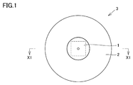
- FIG. 1 is a plan view of a tool with a through hole according to an embodiment of the present disclosure.
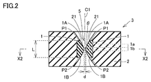
- FIG. 2 is a cross-sectional view taken along line X1-X1 of the tool with through holes shown in FIG.
- FIG. 3 is a cross-sectional view of the through-hole tool shown in FIG. 2 taken along line X2-X2.
- FIG. 4 is a diagram showing a region S1 surrounded by the outer shape of the diamond component shown in FIG.
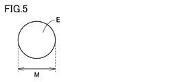
- FIG. 5 is a diagram showing an equal area circle of the region S1 shown in FIG.
- FIG. 6 is a sectional view of a conventional tool with a through hole.
- FIG. 7 is a plan view of the diamond component according to one embodiment of the present disclosure.
- FIG. 1 is a plan view of a tool with a through hole according to an embodiment of the present disclosure.
- FIG. 2 is a cross-sectional view taken along line X1-X1 of the tool with through holes shown in FIG.
- FIG. 3 is
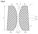
- FIG. 8 is a cross-sectional view of the diamond component shown in FIG. 7 taken along line X3-X3.
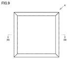
- FIG. 9 is a plan view of a diamond material according to an embodiment of the present disclosure.
- FIG. 10 is a cross-sectional view taken along line X4-X4 of the diamond material shown in FIG.
- FIG. 11 is a schematic diagram of a cutting jig and a cutting auxiliary jig used for laser cutting of a diamond material.
- FIG. 12 is a top view of the cutting jig and the cutting auxiliary jig shown in FIG.
- an object of the present invention is to provide a tool with a through-hole that can have a long tool life even in high-efficiency processing of a high-strength wire, a diamond component that can be used for the tool with a through-hole, and a diamond material.
- the purpose is to do.
- the through-hole tool can have a long tool life even in high-efficiency processing of a high-strength wire.
- a tool with a through hole includes: A tool with a through-hole comprising a base material and a diamond component held by the base material, When the diamond component has a length along a center line of the through hole as L1 and a maximum value of a diameter of an equal area circle of a region surrounded by an outer edge of a cross section with the center line as a normal line, M1 L1 / M1 which is the ratio between L1 and M1 is 0.8 or more, and is a tool with through holes.
- the through-hole tool can have a long tool life even in high-efficiency processing of a high-strength wire.
- the L1 is preferably 0.5 mm or more and 50 mm or less, and the M1 is preferably 0.5 mm or more and 56 mm or less. According to this, the diamond component can have excellent wear resistance.
- the through hole preferably has a minimum diameter of 0.001 mm or more and 15 mm or less. This tool with a through-hole can handle a wide range of hole diameters, and is therefore highly convenient as a tool.
- an angle ⁇ between an entrance side surface of the through hole and an exit side surface P2 of the through hole is 0 ° or more and 1 ° or less. This diamond component is unlikely to fall when placed in a concave portion of the base material during the production of a tool with through holes. Therefore, it becomes easy to manufacture a tool with a through hole.
- the diamond component is preferably made of synthetic single crystal diamond.
- Single crystal diamond is easy to process into a desired shape. Therefore, a tool with a through hole can be efficiently manufactured.
- the synthetic single crystal diamond preferably contains nitrogen atoms at a concentration of 0.01 ppb or more and 3000 ppm or less. According to this, the wear resistance of the tool with the through hole is improved. Furthermore, this synthetic single crystal diamond is hard to be broken at the time of manufacturing a tool with a through hole.
- the synthetic single crystal diamond preferably contains boron atoms at a concentration of 0.5 ppb or more and 10000 ppm or less. According to this, the wear resistance of the tool with the through hole is improved. Furthermore, this synthetic single crystal diamond is hard to be broken at the time of manufacturing a tool with a through hole.
- the synthetic single crystal diamond preferably contains silicon atoms at a concentration of 0.0001 ppb or more and 10000 ppm or less. According to this, the wear resistance of the tool with the through hole is improved. Furthermore, this synthetic single crystal diamond is hard to be broken at the time of manufacturing a tool with a through hole.
- the synthetic single crystal diamond preferably contains a total of impurity atoms other than nitrogen atoms, boron atoms and silicon atoms in a concentration of 0.5 ppb or more and 10000 ppm or less. According to this, the wear resistance of the tool with the through hole is improved. Furthermore, this synthetic single crystal diamond is hard to be broken at the time of manufacturing a tool with a through hole.
- the synthetic single crystal diamond preferably has a phase difference of 0.1 nm or more and 200 nm or less when irradiated with circularly polarized light. According to this, it is possible to suppress the occurrence of chipping of the diamond component when using the tool with the through hole.
- the surface on the entrance side of the through-hole is a (111) surface, a (100) surface, or a (110) surface. According to this, the uneven wear of the diamond part and the wear resistance of the diamond part which occur when the tool with the through hole is used can be controlled according to the requirement of the material to be penetrated.
- the diamond component is preferably made of polycrystalline diamond. According to this, when a tool with a through-hole is used, the occurrence of cracks and the development of cracks in the diamond component and the uneven wear of the diamond component can be suppressed.
- the tool with a through hole is preferably a die, a water jet nozzle, or a wire guide. These through-hole tools can have excellent tool life.
- the diamond component according to an embodiment of the present disclosure includes: A diamond component having a through hole, The diamond component has a length L1 along a center line of the through hole, and a maximum value of a diameter of an equal area circle of a region surrounded by an outer edge of a cross section having the center line as a normal line, and M1.
- L1 / M1 which is a ratio of the L1 and the M1 is 0.8 or more.
- the through-hole tool provided with the diamond component can have an excellent tool life.
- the diamond material according to an embodiment of the present disclosure includes: A diamond material for use with through-hole tools, The diamond material has a length L2 along a center line of the through hole when a through hole is formed, and a maximum value M2 of a diameter of a circle having an equal area of a cross section having the center line as a normal line.
- L2 / M2, which is the ratio of L2 to M2, is 0.8 or more.
- the diamond material includes: A diamond material for use with through-hole tools,
- the diamond material is made of single crystal diamond,
- the diamond material has a first surface composed of a (111) plane, a (100) plane, or a (110) plane,
- L2 and M2 are equal to each other.
- L2 / M2 which is a ratio of 0.8 or more, is a diamond material.
- a tool with a through hole manufactured using this diamond material can have an excellent tool life.
- FIG. 1 is a plan view of a tool with a through hole according to an embodiment of the present disclosure.
- FIG. 2 is a cross-sectional view taken along line X1-X1 of the tool with through holes shown in FIG.
- FIG. 3 is a cross-sectional view of the through-hole tool shown in FIG. 2 taken along line X2-X2.
- FIG. 4 is a diagram showing an equal-area circle of a cross section of the diamond component shown in FIG.
- FIG. 6 is a sectional view of a conventional tool with a through hole.
- the through-hole tool 3 includes a base material 2 and a diamond component 1 held by the base material 2.
- the base material 2 holds the diamond component 1.
- a material of the base material 2 a sintered alloy, stainless steel, or the like can be used.
- the shape of the base material 2 is not limited to the shape shown in FIG. 1, and can be appropriately changed according to the use of the tool with through holes.
- a sintered alloy or a brazing material may be present as a joining material between the base material 2 and the diamond component 1.
- the diamond component 1 includes an entrance 1A and an exit 1B, a material to be penetrated through the through hole is inserted from the entrance 1A side, and the material to be penetrated is discharged from the exit 1B side.
- the diamond component 1 includes a first region 1b in which the diameter d of the through hole is a minimum value, and a second region 1a connected to the first region 1b and arranged on the entrance 1A side of the through hole.
- the diamond component 1 and the base material 2 are provided with through holes 5 extending from the inlet 1A to the outlet 1B, and the through holes 5 are defined by the wall surface 21.
- the inclination of the wall surface 21 changes gradually with respect to the center line C1 as the center axis.
- the center line C1 is a straight line
- the through hole 5 has a shape symmetric with respect to the center line C1.
- the diamond component 1 has a length (length indicated by L in FIG. 2) along the center line C1 of the through hole as L1, and an equal area circle of a region surrounded by an outer edge of a cross section having the center line C1 as a normal line.
- L1 / M1 (hereinafter, also referred to as ratio (L1 / M1)), which is the ratio between L1 and M1, is 0.8 or more.
- the region surrounded by the outer edge of the cross section having the center line C1 of the diamond component 1 as a normal is defined as a region S1 (see FIG. 3 and FIG. 4) surrounded by the outer edge O of the diamond component 1 (see FIGS. 3 and 4).
- the area of the region S1 is the entire area surrounded by the outer edge O, and includes the area corresponding to the through hole.
- the diameter of the equal area circle of the region S1 means the diameter M of the equal area circle E of the region S1 (see FIG. 5).
- the maximum value of the diameter M is M1.
- the through-hole tool of the present embodiment can have a long tool life even in high-efficiency processing of a high-strength wire. For the reason, the present inventors presume as follows.
- One of the causes of shortening the tool life of a tool with a through hole is abrasion of a diamond part due to the use of a tool with a through hole.
- This wear includes reactive wear in which diamond is graphitized by frictional heat generated by friction between a diamond component and a material to be penetrated through a through-hole, and mechanical friction generated by friction between a diamond component and a material to be penetrated. It is believed that wear contributes. In the through-hole tool of the present embodiment, both reactive wear and mechanical wear are suppressed, so that the tool life is considered to be long. The reason is presumed as follows (i) and (ii).
- the diamond component 11 had a square main surface in a plate shape.
- the length (length L shown in FIG. 6) L1 of the through-hole along the center line C1 is perpendicular to the center line C1 (horizontal direction in FIG. 6). Is much shorter than the length L3, and the ratio (L1 / L3) between L1 and L3 is, for example, 0.6 or more and 0.75 or less.
- the ratio (L1 / M1) between the length L1 (length indicated by L in FIG. 2) along the center line C1 of the through hole and M1 is 0.8 or more.
- the ratio of the length L1 is larger than in the conventional example.
- the diamond component when the length of the diamond component in the direction perpendicular to the center line C1 (the horizontal direction in FIGS. 2 and 6) is the same and the shape of the through-hole is the same, the diamond component has the same shape.
- the volume of the present embodiment is larger than that of the conventional example.
- the length of the diamond component in the direction perpendicular to the center line C1 is the same as the conventional example, the length in the direction along the center line C1 is long.
- the length L1 is longer than in the conventional example. Therefore, in the present embodiment, the degree of freedom in designing the shape of the through-hole is increased, and it is possible to form a through-hole having an optimal shape for suppressing mechanical wear on the diamond component. Thereby, it is presumed that the tool life of the tool with a through hole of the present embodiment is prolonged.
- the ratio (L1 / M1) of L1 and M1 is preferably 0.9 or more, more preferably 1.0 or more, and still more preferably 1.3 or more.
- the upper limit of the ratio (L1 / M1) is not particularly limited, but is preferably, for example, 1.4 or less. That is, the ratio (L1 / M1) is preferably 0.8 or more and 1.4 or less, more preferably 0.9 or more and 1.4 or less, preferably 1.0 or more and 1.4 or less, and 1.3 or more and 1.4 or less. The following is preferred.
- the shape of the surface P1 on the entrance 1A side and the surface P2 on the exit 1B side of the diamond component 1 are not particularly limited, but may be squares having substantially the same area. That is, the diamond component 1 can have a prism shape as a whole.
- the area of two squares having substantially the same area means that the difference between the areas of the two squares is within 5% based on the smaller area.
- the ratio (L1 / D) of the length L1 along the center line of the through hole to the length D of one side of the surfaces P1 and P2 is preferably 0.8 or more. According to this, the wear resistance of the diamond component 1 is improved by the same mechanism as when the value of the ratio (L1 / M1) is 0.8 or more.
- Ratio (L1 / D) is preferably 1.0 or more, more preferably 1.1 or more.
- the upper limit of the ratio (L1 / D) is not particularly limited, but is preferably, for example, 1.5 or less. That is, the ratio (L1 / D) is preferably 0.8 or more and 1.5 or less, preferably 1.0 or more and 1.5 or less, and more preferably 1.1 or more and 1.5 or less. If the length of one side of the plane P1 is different from the length of one side of the plane P2, D indicates the length of the longer side.
- the length L1 of the through hole along the center line C1 is 0.5 mm or more and 50 mm or less, and the diameter of the area S1 surrounded by the outer edge of the cross section having the center line C1 as a normal is equal to the diameter of the circle.
- the maximum value M1 is preferably 0.5 mm or more and 60 mm or less.
- the diamond component 1 since the diamond component 1 has a sufficiently large volume, it can have excellent heat dissipation. Therefore, reactive wear of the diamond component can be suppressed. Further, since the length of the diamond component 1 along the center line C1 is sufficiently long, the degree of freedom in designing the through-hole is increased. Therefore, the optimal shape of the through hole for suppressing mechanical wear can be applied to the diamond component 1, and the mechanical wear of the diamond component 1 can be suppressed.
- L1 is more preferably 0.5 mm or more and 50 mm or less, and still more preferably 0.5 mm or more and 25 mm or less.
- M1 is more preferably 0.5 mm or more and 56 mm or less, and still more preferably 0.5 mm or more and 31 mm or less.
- the through hole 5 preferably has a minimum diameter (length indicated by d in FIG. 2) of 0.001 mm or more and 15 mm or less.
- This tool with a through-hole can handle a wide range of hole diameters, and is therefore highly convenient as a tool.
- the minimum value d of the diameter is more preferably 0.005 mm or more and 10 mm or less, and still more preferably 0.01 mm or more and 5 mm or less.
- the angle ⁇ formed between the surface P1 on the entrance 1A side of the through hole 5 and the surface P2 on the exit 1B side of the through hole 5 is 0 ° or more and 1 ° or less.
- This diamond component is unlikely to fall when placed in a concave portion of the base material during the production of a tool with through holes. Therefore, a tool with a through hole can be efficiently manufactured.
- the angle ⁇ is more preferably 0 ° or more and 0.75 ° or less, further preferably 0 ° or more and 0.5 ° or less.
- the angle ⁇ (not shown) formed between the plane P1 and the plane P2 is assumed to be a virtual plane P1 ′ and a virtual plane P2 ′ obtained by enlarging the planes P1 and P2, respectively. And the virtual plane P2 ′.
- the material of the diamond component 1 is not particularly limited, and any of single crystal diamond, polycrystal diamond and sintered diamond can be used.
- the single crystal diamond examples include natural diamond and synthetic single crystal diamond.
- Synthetic single crystal diamond is suitable as a material for the diamond component of the present embodiment because it can be easily processed into a desired shape and a tool with through holes can be efficiently produced.
- the method for producing the synthetic single crystal diamond is not particularly limited. For example, a synthetic single crystal diamond manufactured using a high-pressure synthesis method or a gas-phase synthesis method can be used.
- Synthetic single crystal diamond preferably contains nitrogen atoms at a concentration of 0.01 ppb or more and 3000 ppm or less. According to this, the wear resistance of the tool with the through hole is improved. Furthermore, this synthetic single crystal diamond is hard to be broken at the time of manufacturing a tool with a through hole.
- the concentration of nitrogen atoms in the synthetic single crystal diamond is more preferably from 0.1 ppm to 500 ppm, further preferably from 1 ppm to 200 ppm.
- Synthetic single crystal diamond preferably contains boron atoms at a concentration of 0.5 ppb or more and 10000 ppm or less. According to this, the wear resistance of the tool with the through hole is improved. Furthermore, this synthetic single crystal diamond is hard to be broken at the time of manufacturing a tool with a through hole.
- the concentration of boron atoms in the synthetic single crystal diamond is more preferably 0.5 ppb or more and 1 ppm or less, further preferably 0.5 ppb or more and 0.5 ppm or less.
- Synthetic single crystal diamond preferably contains silicon atoms at a concentration of 0.0001 ppb or more and 10000 ppm or less. According to this, the wear resistance of the tool with the through hole is improved. Furthermore, this synthetic single crystal diamond is hard to be broken at the time of manufacturing a tool with a through hole.
- the concentration of silicon atoms in the synthetic single crystal diamond is more preferably from 0.003 ppm to 100 ppm, more preferably from 0.01 ppm to 50 ppm, and even more preferably from 0.1 ppm to 25 ppm.
- the synthetic single crystal diamond preferably contains a total of impurity atoms other than nitrogen atom, boron atom and silicon atom in a concentration of 0.5 ppb or more and 10000 ppm or less.
- the impurity atom include hydrogen, aluminum, titanium, chromium, copper, tungsten, and iridium. According to this, the wear resistance of the tool with the through hole is improved. Furthermore, this synthetic single crystal diamond is hard to be broken at the time of manufacturing a tool with a through hole.
- the total concentration of impurity atoms in the synthetic single crystal diamond is more preferably 0.5 ppb or more and 5000 ppm or less, further preferably 0.1 ppm or more and 3000 ppm or less.
- the concentrations of nitrogen atoms, boron atoms, silicon atoms, and other impurity atoms in the synthetic single crystal diamond are measured by secondary ion mass spectrometry (SIMS).
- SIMS 7f product name manufactured by CAMECA is used.
- the acceleration voltage is set to 15 kV
- the detection area is set to 35 ⁇ m ⁇
- the concentration at the place where the sputtering is performed from the outermost surface of the sample to a depth of 0.5 ⁇ m is obtained.
- the concentration determination is performed by comparison with a separately prepared standard sample (single-crystal diamond having a known impurity concentration, which is manufactured by ion implantation). If the impurity concentration is small, the measured value may deviate from the true value depending on the accuracy of the device. In order to obtain more accurate values, measurement was performed at a depth of 0.5 ⁇ m at five points at least 100 ⁇ m apart from each other, an average value of the five points was calculated, and this average value was calculated for each atom. Concentration.
- the synthetic single crystal diamond preferably has a phase difference of 0.1 nm or more and 200 nm or less when irradiated with circularly polarized light.
- the phase difference in the synthetic single crystal diamond indicates that a defect exists in the synthetic single crystal diamond.
- the retardation is more preferably from 10 nm to 200 nm, and still more preferably from 30 nm to 300 nm.
- the phase difference is measured according to the following procedures (a-1) to (a-3).
- a diamond part is processed into a plate shape having a thickness of 700 ⁇ m.
- the thickness of the diamond component may be processed using, for example, polishing or etching. If a diamond part cannot be processed to a thickness of 700 ⁇ m, the phase difference described below is measured without performing the above processing, and the measured value is converted to a case of a thickness of 700 ⁇ m in proportion to the plate thickness. You may.
- the diamond component 1 is made of synthetic single crystal diamond, it is preferable that the diamond component 1 has a surface P1 on the entrance side of the through-hole 5 formed of a (111) plane, a (100) plane, or a (110) plane. According to this, the uneven wear of the diamond part and the wear resistance of the diamond part which occur when the tool with the through hole is used can be controlled according to the requirement of the material to be penetrated.
- the material to be penetrated can have a uniform cross-sectional shape.
- the polishing is easy, and the forming process of the through-hole is easy, which is advantageous in terms of manufacturing cost.
- the plane P1 is the (110) plane
- the surface roughness of the material to be penetrated for example, a drawn wire or the like
- the diamond component is preferably made of polycrystalline diamond.
- Polycrystalline diamond has excellent hardness and does not have directionality or cleavage of hardness. Therefore, when polycrystalline diamond is used for the diamond component, it is possible to suppress the occurrence of cracks, the development of cracks, and the uneven wear of the diamond component when using a tool with through holes.
- the method of producing polycrystalline diamond is not particularly limited.
- polycrystalline diamond obtained by sintering a carbon material having a graphite-type layered structure at an ultra-high temperature and a high pressure without adding a sintering agent or a catalyst can be used.
- the tool with a through hole according to an embodiment of the present disclosure can be applied to a die.
- This die can suppress reactive wear and mechanical wear caused by friction between the diamond member and the drawn wire, and therefore can have an excellent tool life.
- Embodiment 3 Water jet nozzle>
- the tool with a through hole according to an embodiment of the present disclosure can be applied to a water jet nozzle. Since this water jet nozzle can suppress reactive wear and mechanical wear caused by friction between the diamond member and water, it can have an excellent tool life.
- Wire guide> The tool with a through hole according to an embodiment of the present disclosure can be applied to a wire guide. Since this wire guide can suppress reactive wear and mechanical wear caused by friction between the diamond member and the wire, it can have an excellent tool life.
- FIG. 7 is a plan view of the diamond component according to one embodiment of the present disclosure.
- FIG. 8 is a cross-sectional view of the diamond component shown in FIG. 7 taken along line X3-X3.
- the diamond component 1 is a diamond component 1 having a through-hole 5, and the diamond component 1 has a length along a center line C ⁇ b> 1 of the through-hole 5 (
- M1 maximum value of the diameter of an equal area circle of the region S1 surrounded by the outer edge of the cross section having the center line C1 as a normal
- L1 and M1 are equal to each other.
- (L1 / M1) is 0.8 or more.
- the shape of the diamond material is a truncated square pyramid, but the shape of the diamond material is not limited to a truncated square pyramid as long as the ratio (L1 / M1) is 0.8 or more.
- a square pole, a cylinder, a truncated cone, or the like can be employed.
- the through-hole tool provided with the diamond component can have an excellent tool life. The reason is as described in the first embodiment.
- FIG. 9 is a plan view of a diamond material according to an embodiment of the present disclosure.
- FIG. 10 is a cross-sectional view taken along line X4-X4 of the diamond material shown in FIG.
- the diamond material 4 is a diamond material to be used for a tool with a through hole, and has a length along the center line of the through hole when the through hole is formed (FIG. 10).
- L2 / M2 (hereinafter referred to as the ratio of L2 to M2), where L2 is the length indicated by L in FIG. , Ratio (L2 / M2)) is 0.8 or more.
- the shape of the diamond material is a truncated square pyramid, but the shape of the diamond material is not limited to a truncated square pyramid as long as the ratio (L2 / M2) is 0.8 or more.
- a square pole, a cylinder, a truncated cone, or the like can be employed.
- a diamond member manufactured by forming a through hole in the diamond material 4 can have the configuration of the diamond member described in the fifth embodiment. Therefore, a tool with a through-hole provided with a diamond member produced using this diamond material can have an excellent tool life.
- the diamond material 4 is a synthetic single crystal diamond material for use in a tool with a through hole, and the synthetic single crystal diamond material has a (111) plane and a (100) plane.
- the diamond material has a first surface composed of a (110) plane, and the diamond material has a length along the normal line of the first surface (length indicated by L in FIG. 10) as L2 and is parallel to the first surface.
- the ratio (L2 / M2) between L2 and M2 is 0.8 or more.
- a diamond member formed by forming a through hole parallel to the normal of the first surface in the diamond material 4 can have the configuration of the diamond member described in the fifth embodiment. Therefore, a tool with a through-hole provided with a diamond member produced using this diamond material can have an excellent tool life.
- ⁇ Embodiment 8 Method for manufacturing tool with through hole (1)> An example of a method for manufacturing a tool with a through hole according to an embodiment of the present disclosure will be described. In this embodiment, a case where the diamond member is made of synthetic single crystal diamond will be described.
- the method for manufacturing a tool with a through hole according to the present embodiment includes a step of manufacturing a synthetic single crystal diamond (hereinafter, also referred to as a “synthetic single crystal diamond manufacturing step”) and a step of manufacturing a diamond material (hereinafter, “diamond material manufacturing”). Step), and a step of manufacturing a tool with a through-hole (hereinafter, also referred to as a “step of manufacturing a tool with a through-hole”).
- a synthetic single crystal diamond is produced by using, for example, a high-pressure synthesis method or a chemical vapor deposition (CVD) method. It is preferable to use the CVD method because the concentration of nitrogen atoms, boron atoms, silicon atoms, and other impurities in the synthetic single crystal diamond and the amount of defects can be easily controlled.
- CVD chemical vapor deposition
- single crystal diamond is grown on a seed substrate placed on a substrate holder of a CVD growth furnace.
- a known general method such as a hot filament method, a combustion flame method, and an arc jet method can be used.
- the concentration of nitrogen, boron, silicon, and other impurities in the synthetic single crystal diamond can be adjusted by adjusting the raw material gas ratio, internal components of the synthesis furnace, synthesis temperature, and the like.
- the amount of defects in the synthetic single crystal diamond can be adjusted by the surface roughness of the seed substrate, surface treatment before synthesis, and the like.
- a single crystal diamond formed on a seed substrate is cut into a desired shape by laser cutting to produce a diamond material.
- the thickness of the cut diamond material can be made a desired thickness.
- This thickness is equal to the length L2 along the center line of the through-hole when the through-hole in the diamond material described in the sixth embodiment is formed, and the normal to the first surface of the diamond material described in the seventh embodiment.
- the length corresponds to the length L2 along the first surface (the upper surface in FIG. 10) P21 or the length of one side of the second surface P22 substantially parallel to the second surface. These lengths are maintained in later steps.
- the length L2 in the diamond material is the same as the length L1 along the center line of the through hole in the diamond component, and the length of one side of the first surface P21 and the second surface P22 in the diamond material is , P1 and P2 have the same value as the length of one side.
- a slitting assisting jig 51 as shown in FIGS. 11 and 12 is used for laser cutting.
- one end of the synthetic single crystal diamond is held by the cutting jig 50, and the cutting auxiliary jig 51 with a slit is installed below the synthetic single crystal diamond, and the synthetic single crystal diamond is moved from below.
- Perform laser cutting while supporting Since the laser light is applied so as to pass through the slit, no reflection of the laser light occurs. Since the synthetic single crystal diamond is supported by the cutting auxiliary jig 51, even if the synthetic single crystal diamond is cut out thickly, the synthetic single crystal diamond does not break during cutting. Therefore, in the obtained diamond material, generation of burrs is suppressed.
- the conditions for laser cutting can be, for example, a laser wavelength of 532 mn, a repetition frequency of 6 kHz to 10 kHz, and an output of 3 W to 20 W.
- the obtained diamond material is arranged in a concave portion of the base material together with a bonding material such as a sintered alloy powder.
- a heat treatment is performed to sinter the binder, and join the diamond material and the base material to obtain a joined body.
- a through-hole is formed in the obtained joined body by laser irradiation, and a tool with a through-hole including a diamond component can be manufactured.
- ⁇ Embodiment 9 Manufacturing method of tool with through hole (2)> An example of a method for manufacturing a tool with a through hole according to an embodiment of the present disclosure will be described. In this embodiment, a case where the diamond member is made of polycrystalline diamond will be described.
- the method for producing a tool with through holes according to the present embodiment includes a step of producing polycrystalline diamond (hereinafter, also referred to as a “polycrystalline diamond producing step”) and a step of producing a diamond material (hereinafter, “diamond material producing step”). ) And a step of manufacturing a tool with a through hole (hereinafter, also referred to as a “tool manufacturing step with a through hole”).
- Polycrystalline diamond production process Polycrystalline diamond is produced, for example, by sintering a carbon material having a graphite-type layered structure under ultra-high temperature and high pressure without adding a sintering aid or a catalyst.
- a tool (die) with through-holes made of synthetic single crystal diamond was produced and evaluated.
- the specific production method and evaluation method are as follows.
- Synthetic single crystal diamond was produced by the CVD method. First, a single crystal diamond seed substrate having a square main surface of 5 mm ⁇ 5 mm and a thickness of 0.5 mm was prepared. This is flattened by polishing, and thereafter, oxygen (O 2 ) gas and hydrogen fluoride (CF 4 ) gas are used as a pretreatment for controlling defects in the synthetic single crystal diamond to a thickness of 0.01 ⁇ m to 0.5 ⁇ m. Dry etching was performed to a depth region. An epitaxial growth layer made of single crystal diamond was formed on this substrate to a thickness of 1 mm.
- oxygen (O 2 ) gas and hydrogen fluoride (CF 4 ) gas are used as a pretreatment for controlling defects in the synthetic single crystal diamond to a thickness of 0.01 ⁇ m to 0.5 ⁇ m. Dry etching was performed to a depth region.
- An epitaxial growth layer made of single crystal diamond was formed on this substrate to a thickness of 1 mm.
- a mixed gas of hydrogen (H 2 ) gas, methane (CH 4 ) gas, and nitrogen (N 2 ) gas was used as a source gas.
- Volume ratio of CH 4 gas to H 2 gas (CH 4 gas / H 2 gas) was 5 to 20% by volume, the volume ratio of the N 2 gas to CH 4 gas (N 2 gas / CH 4 gas) 0.01 -5% by volume.
- the pressure was set at 9.3 to 14.7 kPa, and the substrate temperature was set at 850 to 1200 ° C.
- the impurity concentration can be controlled by the source gas ratio, the components inside the synthesis furnace, the synthesis temperature, and the like, and the defect amount can be controlled by the flatness of the surface of the single crystal diamond seed substrate and the presence or absence of a polishing damage layer.
- the single-crystal diamond produced above is laser-cut while being supported using the cutting jig and the slit-provided auxiliary jig shown in FIGS. 11 and 12, thereby forming a square pillar having a square bottom and top surface. Diamond material was produced.
- the angle ⁇ between the bottom surface and the top surface of the diamond material was 0.5 ° or less.
- the bottom surface and the top surface were (110) planes.
- the bottom surface and the top surface were (111) planes.
- the obtained diamond material was arranged in a concave portion of a base material (material: sintered alloy) such that the bottom surface of the diamond material was substantially parallel to the bottom surface of the concave portion.
- a spray paste was applied as an adhesive between the bottom surface of the concave portion and the diamond material so that the diamond material did not tilt.
- a bonding material made of a sintered alloy powder was sealed in the gap between the concave portions.
- a heat treatment was performed to sinter the binder, and the diamond material and the base material were joined to obtain a joined body.
- a continuous through hole was formed in the obtained joined body from the top surface to the bottom surface of the diamond material by laser irradiation, and a tool with a through hole was manufactured.
- the upper surface of the diamond material becomes a surface P1 on the entrance side of the through hole
- the bottom surface becomes a surface P2 on the exit side of the through hole.
- the minimum diameter d of the through hole was 0.080 mm
- the length along the center line of the first region was 16 ⁇ m
- the angle ⁇ between the wall surface of the diamond component defining the second region and the center line was 12 °.
- ⁇ Drawing test> A wire drawing test of a wire (diameter ⁇ : 86.63 ⁇ m, material: SUS304) was performed using the obtained tool with a through hole. At the time of wire drawing, a synthetic oil-based lubricant was used. The drawing speed was 500 m / min, and the area reduction rate was 14%.
- Sample 1 has a ratio (L1 / M1) of 0.665, which corresponds to Comparative Example.
- Samples 2 to 11 have ratios (L1 / M1) of 0.8 or more, and correspond to Examples. It was confirmed that Samples 2 to 11 (Examples) exhibited superior wear resistance in high-efficiency processing of a high-strength wire rod as compared with Sample 1 (Comparative Example).
Landscapes
- Chemical & Material Sciences (AREA)
- Organic Chemistry (AREA)
- Engineering & Computer Science (AREA)
- Materials Engineering (AREA)
- Metallurgy (AREA)
- Mechanical Engineering (AREA)
- Inorganic Chemistry (AREA)
- Crystallography & Structural Chemistry (AREA)
- General Chemical & Material Sciences (AREA)
- Chemical Kinetics & Catalysis (AREA)
- General Life Sciences & Earth Sciences (AREA)
- Geology (AREA)
- Life Sciences & Earth Sciences (AREA)
- Crystals, And After-Treatments Of Crystals (AREA)
- Metal Extraction Processes (AREA)
- Carbon And Carbon Compounds (AREA)
- Processing Of Stones Or Stones Resemblance Materials (AREA)
- Chemical Vapour Deposition (AREA)
- Cutting Tools, Boring Holders, And Turrets (AREA)
Abstract
基材と、前記基材に保持されたダイヤモンド部品とを備える貫通孔付工具であって、前記ダイヤモンド部品は、貫通孔の中心線に沿う長さをL1とし、前記中心線を法線とする断面の外縁に囲まれる領域の等面積円の直径の最大値をM1とした場合に、前記L1と前記M1との比であるL1/M1は0.8以上である。
Description
本開示は、貫通孔付工具、ダイヤモンド部品、及び、ダイヤモンド素材に関する。本出願は、2018年6月27日に出願した日本特許出願である特願2018-121764号に基づく優先権を主張する。当該日本特許出願に記載された全ての記載内容は、参照によって本明細書に援用される。
ダイヤモンドは、極めて高い硬度を有しているため、ダイス、ウォータージェットノズル、ワイヤーガイド等の耐磨工具に使用されている。
特開平5-169131号公報(特許文献1)には、貫通して形成された孔を有し、支持体に取り付けられた多結晶CVDダイヤモンド層を含む線引きダイが開示されている。
本開示の一態様に係る貫通孔付工具は、
基材と、前記基材に保持されたダイヤモンド部品とを備える貫通孔付工具であって、
前記ダイヤモンド部品は、貫通孔の中心線に沿う長さをL1とし、前記中心線を法線とする断面の外縁に囲まれる領域の等面積円の直径の最大値をM1とした場合に、前記L1と前記M1との比であるL1/M1は0.8以上である、貫通孔付工具である。
基材と、前記基材に保持されたダイヤモンド部品とを備える貫通孔付工具であって、
前記ダイヤモンド部品は、貫通孔の中心線に沿う長さをL1とし、前記中心線を法線とする断面の外縁に囲まれる領域の等面積円の直径の最大値をM1とした場合に、前記L1と前記M1との比であるL1/M1は0.8以上である、貫通孔付工具である。
本開示の一態様に係るダイヤモンド部品は、
貫通孔を備えるダイヤモンド部品であって、
前記ダイヤモンド部品は、貫通孔の中心線に沿う長さをL1とし、前記中心線を法線とする断面の外縁に囲まれる領域の等面積円の直径の最大値をM1とした場合に、前記L1と前記M1との比であるL1/M1は0.8以上である、ダイヤモンド部品である。
貫通孔を備えるダイヤモンド部品であって、
前記ダイヤモンド部品は、貫通孔の中心線に沿う長さをL1とし、前記中心線を法線とする断面の外縁に囲まれる領域の等面積円の直径の最大値をM1とした場合に、前記L1と前記M1との比であるL1/M1は0.8以上である、ダイヤモンド部品である。
本開示の一態様に係るダイヤモンド素材は、
貫通孔付工具に用いるためのダイヤモンド素材であって、
前記ダイヤモンド素材は、貫通孔が形成された場合の前記貫通孔の中心線に沿う長さをL2とし、前記中心線を法線とする断面の等面積円の直径の最大値をM2とした場合に、前記L2と前記M2との比であるL2/M2は0.8以上である、ダイヤモンド素材である。
貫通孔付工具に用いるためのダイヤモンド素材であって、
前記ダイヤモンド素材は、貫通孔が形成された場合の前記貫通孔の中心線に沿う長さをL2とし、前記中心線を法線とする断面の等面積円の直径の最大値をM2とした場合に、前記L2と前記M2との比であるL2/M2は0.8以上である、ダイヤモンド素材である。
本開示の一態様に係るダイヤモンド素材は、
貫通孔付工具に用いるためのダイヤモンド素材であって、
前記ダイヤモンド素材は、単結晶ダイヤモンドからなり、
前記ダイヤモンド素材は、(111)面、(100)面、又は、(110)面からなる第1面を有し、
前記ダイヤモンド素材は、前記第1面の法線に沿う長さをL2とし、前記第1面に平行な断面の等面積円の直径の最大値をM2とした場合に、前記L2と前記M2との比であるL2/M2は0.8以上である、ダイヤモンド素材である。
貫通孔付工具に用いるためのダイヤモンド素材であって、
前記ダイヤモンド素材は、単結晶ダイヤモンドからなり、
前記ダイヤモンド素材は、(111)面、(100)面、又は、(110)面からなる第1面を有し、
前記ダイヤモンド素材は、前記第1面の法線に沿う長さをL2とし、前記第1面に平行な断面の等面積円の直径の最大値をM2とした場合に、前記L2と前記M2との比であるL2/M2は0.8以上である、ダイヤモンド素材である。
[本開示が解決しようとする課題]
近年、伸線素材の高強度化とともに、高能率加工の要求が厳しくなっている。従来のダイスを高強度線材の高能率加工に適用する場合、ダイスの摩耗が生じやすく、工具寿命が短くなる傾向がある。
近年、伸線素材の高強度化とともに、高能率加工の要求が厳しくなっている。従来のダイスを高強度線材の高能率加工に適用する場合、ダイスの摩耗が生じやすく、工具寿命が短くなる傾向がある。
そこで、本目的は、高強度線材の高能率加工においても、長い工具寿命を有することができる貫通孔付工具、並びに、該貫通孔付工具に用いることのできるダイヤモンド部品、及び、ダイヤモンド素材を提供することを目的とする。
[本開示の効果]
上記態様によれば、貫通孔付工具は、高強度線材の高能率加工においても、長い工具寿命を有することができる。
[本開示の実施形態の説明]
最初に本開示の実施態様を列記して説明する。
[本開示の効果]
上記態様によれば、貫通孔付工具は、高強度線材の高能率加工においても、長い工具寿命を有することができる。
[本開示の実施形態の説明]
最初に本開示の実施態様を列記して説明する。
(1)本開示の一実施の形態に係る貫通孔付工具は、
基材と、前記基材に保持されたダイヤモンド部品とを備える貫通孔付工具であって、
前記ダイヤモンド部品は、貫通孔の中心線に沿う長さをL1とし、前記中心線を法線とする断面の外縁に囲まれる領域の等面積円の直径の最大値をM1とした場合に、前記L1と前記M1との比であるL1/M1は0.8以上である、貫通孔付工具である。
基材と、前記基材に保持されたダイヤモンド部品とを備える貫通孔付工具であって、
前記ダイヤモンド部品は、貫通孔の中心線に沿う長さをL1とし、前記中心線を法線とする断面の外縁に囲まれる領域の等面積円の直径の最大値をM1とした場合に、前記L1と前記M1との比であるL1/M1は0.8以上である、貫通孔付工具である。
この貫通孔付工具は、高強度線材の高能率加工においても、長い工具寿命を有することができる。
(2)前記L1は、0.5mm以上50mm以下であり、前記M1は、0.5mm以上56mm以下であることが好ましい。これによると、ダイヤモンド部品は優れた耐摩耗性を有することができる。
(3)前記貫通孔は、径の最小値が0.001mm以上15mm以下であることが好ましい。この貫通孔付工具は、幅広い穴径に対応できるため、工具としての利便性が高い。
(4)前記ダイヤモンド部品は、前記貫通孔の入り口側の面と、前記貫通孔の出口側の面P2とのなす角度αが0°以上1°以下であることが好ましい。このダイヤモンド部品は、貫通孔付工具の作製時に、基材の凹部に配置した際に倒れにくい。よって、貫通孔付工具の作製が容易となる。
(5)前記ダイヤモンド部品は、合成単結晶ダイヤモンドからなることが好ましい。単結晶ダイヤモンドは、所望の形状に加工しやすい。よって、貫通孔付工具を効率的に作製することができる。
(6)前記合成単結晶ダイヤモンドは、窒素原子を0.01ppb以上3000ppm以下の濃度で含むことが好ましい。これによると、貫通孔付工具の耐摩耗性が良好となる。更に、この合成単結晶ダイヤモンドは、貫通孔付工具の作製時に割れにくい。
(7)前記合成単結晶ダイヤモンドは、硼素原子を0.5ppb以上10000ppm以下の濃度で含むことが好ましい。これによると、貫通孔付工具の耐摩耗性が良好となる。更に、この合成単結晶ダイヤモンドは、貫通孔付工具の作製時に割れにくい。
(8)前記合成単結晶ダイヤモンドは、珪素原子を0.0001ppb以上10000ppm以下の濃度で含むことが好ましい。これによると、貫通孔付工具の耐摩耗性が良好となる。更に、この合成単結晶ダイヤモンドは、貫通孔付工具の作製時に割れにくい。
(9)前記合成単結晶ダイヤモンドは、窒素原子、硼素原子及び珪素原子以外の不純物原子を合計で0.5ppb以上10000ppm以下の濃度で含むことが好ましい。これによると、貫通孔付工具の耐摩耗性が良好となる。更に、この合成単結晶ダイヤモンドは、貫通孔付工具の作製時に割れにくい。
(10)前記合成単結晶ダイヤモンドは、円偏光を照射した場合に発生する位相差が、0.1nm以上200nm以下であることが好ましい。これによると、貫通孔付工具の使用時に、ダイヤモンド部品に欠けが発生することを抑制することができる。
(11)前記ダイヤモンド部品は、前記貫通孔の入り口側の面が(111)面、(100)面、又は、(110)面からなることが好ましい。これによると、貫通孔付工具の使用時に生じるダイヤモンド部品の偏摩耗、及び、ダイヤモンド部品の耐摩耗性を、被貫通材の要求に応じて制御することができる。
(12)前記ダイヤモンド部品は多結晶ダイヤモンドからなることが好ましい。これによると、貫通孔付工具の使用時に、ダイヤモンド部品における欠けの発生及びクラックの進展、並びに、ダイヤモンド部品の偏摩耗を抑制することができる。
(13)前記貫通孔付工具はダイス、ウォータージェットノズル、又はワイヤーガイドであることが好ましい。これらの貫通孔付工具は、優れた工具寿命を有することができる。
(14)本開示の一実施の形態に係るダイヤモンド部品は、
貫通孔を備えるダイヤモンド部品であって、
前記ダイヤモンド部品は、前記貫通孔の中心線に沿う長さをL1とし、前記中心線を法線とする断面の外縁に囲まれる領域の等面積円の直径の最大値をM1とした場合に、前記L1と前記M1との比であるL1/M1は0.8以上である、ダイヤモンド部品である。
貫通孔を備えるダイヤモンド部品であって、
前記ダイヤモンド部品は、前記貫通孔の中心線に沿う長さをL1とし、前記中心線を法線とする断面の外縁に囲まれる領域の等面積円の直径の最大値をM1とした場合に、前記L1と前記M1との比であるL1/M1は0.8以上である、ダイヤモンド部品である。
このダイヤモンド部品を備える貫通孔付工具は、優れた工具寿命を有することができる。
(15)本開示の一実施の形態に係るダイヤモンド素材は、
貫通孔付工具に用いるためのダイヤモンド素材であって、
前記ダイヤモンド素材は、貫通孔が形成された場合の前記貫通孔の中心線に沿う長さをL2とし、前記中心線を法線とする断面の等面積円の直径の最大値をM2とした場合に、前記L2と前記M2との比であるL2/M2は0.8以上である、ダイヤモンド素材である。
貫通孔付工具に用いるためのダイヤモンド素材であって、
前記ダイヤモンド素材は、貫通孔が形成された場合の前記貫通孔の中心線に沿う長さをL2とし、前記中心線を法線とする断面の等面積円の直径の最大値をM2とした場合に、前記L2と前記M2との比であるL2/M2は0.8以上である、ダイヤモンド素材である。
このダイヤモンド素材を用いて作製された貫通孔付工具は、優れた工具寿命を有することができる。
(16)本開示の一実施の形態に係るダイヤモンド素材は、
貫通孔付工具に用いるためのダイヤモンド素材であって、
前記ダイヤモンド素材は、単結晶ダイヤモンドからなり、
前記ダイヤモンド素材は、(111)面、(100)面、又は、(110)面からなる第1面を有し、
前記ダイヤモンド素材は、前記第1面の法線に沿う長さをL2とし、前記第1面に平行な断面の等面積円の直径の最大値をM2とした場合に、前記L2と前記M2との比であるL2/M2は0.8以上である、ダイヤモンド素材である。
貫通孔付工具に用いるためのダイヤモンド素材であって、
前記ダイヤモンド素材は、単結晶ダイヤモンドからなり、
前記ダイヤモンド素材は、(111)面、(100)面、又は、(110)面からなる第1面を有し、
前記ダイヤモンド素材は、前記第1面の法線に沿う長さをL2とし、前記第1面に平行な断面の等面積円の直径の最大値をM2とした場合に、前記L2と前記M2との比であるL2/M2は0.8以上である、ダイヤモンド素材である。
このダイヤモンド素材を用いて作製された貫通孔付工具は、優れた工具寿命を有することができる。
[本開示の実施形態の詳細]
本開示の一実施形態に係る貫通孔付工具の具体例を、以下に図面を参照しつつ説明する。本開示はこれらの例示に限定されるものではなく、請求の範囲によって示され、請求の範囲と均等の意味および範囲内でのすべての変更が含まれることが意図される。
[本開示の実施形態の詳細]
本開示の一実施形態に係る貫通孔付工具の具体例を、以下に図面を参照しつつ説明する。本開示はこれらの例示に限定されるものではなく、請求の範囲によって示され、請求の範囲と均等の意味および範囲内でのすべての変更が含まれることが意図される。
図面において、同一の参照符号は、同一部分または相当部分を表わすものである。長さ、幅、厚さ、深さなどの寸法関係は図面の明瞭化と簡略化のために適宜変更されており、実際の寸法関係を表わすものではない。
<実施の形態1:貫通孔付工具>
本開示の一実施の形態に係る貫通孔付工具を図1~図6を用いて説明する。図1は、本開示の一態様に係る貫通孔付工具の平面図である。図2は、図1に示される貫通孔付工具のX1-X1線における断面図である。図3は、図2に示される貫通孔付工具のX2-X2線における断面図である。図4は、図3に示されるダイヤモンド部品の断面の等面積円を示す図である。図6は、従来の貫通孔付工具の断面図である。
本開示の一実施の形態に係る貫通孔付工具を図1~図6を用いて説明する。図1は、本開示の一態様に係る貫通孔付工具の平面図である。図2は、図1に示される貫通孔付工具のX1-X1線における断面図である。図3は、図2に示される貫通孔付工具のX2-X2線における断面図である。図4は、図3に示されるダイヤモンド部品の断面の等面積円を示す図である。図6は、従来の貫通孔付工具の断面図である。
図1に示されるように、本実施形態に係る貫通孔付工具3は、基材2と、前記基材2に保持されたダイヤモンド部品1とを備える。
(基材)
基材2は、ダイヤモンド部品1を保持するものである。基材2の素材としては、焼結合金、ステンレス鋼等を用いることができる。
基材2は、ダイヤモンド部品1を保持するものである。基材2の素材としては、焼結合金、ステンレス鋼等を用いることができる。
基材2の形状は、図1に示される形状に限定されず、貫通孔付工具の用途に応じて、適宜変更することができる。
図1~図3には示されていないが、基材2とダイヤモンド部品1との間に、接合材として焼結合金や蝋材が存在していてもよい。
(ダイヤモンド部品)
図2に示されるように、ダイヤモンド部品1は、入り口1A及び出口1Bを含み、入り口1A側から貫通孔を貫通する被貫通材が挿入され、被貫通材は出口1B側から排出される。ダイヤモンド部品1は、貫通孔の径dが最小値の第1領域1bと、第1領域1bに連なり、貫通孔の入り口1A側に配置される第2領域1aとを含む。
図2に示されるように、ダイヤモンド部品1は、入り口1A及び出口1Bを含み、入り口1A側から貫通孔を貫通する被貫通材が挿入され、被貫通材は出口1B側から排出される。ダイヤモンド部品1は、貫通孔の径dが最小値の第1領域1bと、第1領域1bに連なり、貫通孔の入り口1A側に配置される第2領域1aとを含む。
ダイヤモンド部品1及び基材2には、入口1Aから出口1Bまで連なる貫通孔5が設けられており、貫通孔5は壁面21により規定される。壁面21の傾斜は、中心軸としての中心線C1に対して徐々に変化している。図2に示される断面では、中心線C1は直線であり、貫通孔5は中心線C1に対して対称な形状を有している。
ダイヤモンド部品1は、貫通孔の中心線C1に沿う長さ(図2においてLで示される長さ)をL1とし、中心線C1を法線とする断面の外縁に囲まれる領域の等面積円の直径の最大値をM1とした場合に、L1とM1との比であるL1/M1(以下、比(L1/M1)とも記す。)は0.8以上である。本明細書において、ダイヤモンド部品1の中心線C1を法線とする断面の外縁に囲まれる領域とは、断面におけるダイヤモンド部品1の外縁O(図3及び図4参照)により囲まれる領域S1(図4参照)であり、貫通孔を有しないものを意味する。従って、図4に示されるように、領域S1の面積は、外縁Oに囲まれる領域全ての面積であり、貫通孔に相当する面積も含む。領域S1の等面積円の直径とは、領域S1の等面積円Eの直径Mを意味する(図5参照)。直径Mの最大値がM1である。
ダイヤモンド部品1が上記の構成を有することにより、本実施形態の貫通孔付工具は、高強度線材の高能率加工においても、長い工具寿命を有することができる。その理由について、本発明者らは下記の通り推察する。
貫通孔付工具の工具寿命が短くなる原因の一つに、貫通孔付工具の使用に伴うダイヤモンド部品の摩耗が挙げられる。この摩耗には、ダイヤモンド部品と貫通孔を通過する被貫通材との摩擦により生じる摩擦熱により、ダイヤモンドがグラファイト化して摩耗する反応摩耗、及び、ダイヤモンド部品と被貫通材との摩擦により生じる機械的摩耗が寄与すると考えられる。本実施形態の貫通孔付工具では、反応摩耗及び機械的摩耗の両方が抑制されているため、工具寿命が長くなると考えらえる。その理由は下記(i)及び(ii)の通りと推察される。
(i)反応摩耗の抑制
従来の貫通孔付工具13では、ダイヤモンド部品11は、主面が正方形の板状であった。図6に示されるように、従来例では、貫通孔の中心線C1に沿う長さ(図6においてLで示される長さ)L1が、中心線C1に垂直な方向(図6の水平方向)の長さL3よりも非常に短く、L1とL3との比(L1/L3)は、例えば、0.6以上0.75以下であった。
従来の貫通孔付工具13では、ダイヤモンド部品11は、主面が正方形の板状であった。図6に示されるように、従来例では、貫通孔の中心線C1に沿う長さ(図6においてLで示される長さ)L1が、中心線C1に垂直な方向(図6の水平方向)の長さL3よりも非常に短く、L1とL3との比(L1/L3)は、例えば、0.6以上0.75以下であった。
一方、本実施形態に係るダイヤモンド部品1では貫通孔の中心線C1に沿う長さ(図2においてLで示される長さ)L1とM1との比(L1/M1)が0.8以上であり、従来例よりも、長さL1の割合が大きくなっている。
従って、従来例と本実施形態において、ダイヤモンド部品の中心線C1に垂直な方向(図2及び図6の水平方向)の長さが同一、かつ、貫通孔の形状が同一の場合、ダイヤモンド部品の体積は、本実施形態の方が、従来例よりも大きくなる。
ダイヤモンドは熱伝導率が高いため、ダイヤモンド部品の体積が大きいと、ダイヤモンド部品と被貫通材との間で生じる摩擦熱が拡散しやすい。よって、本実施形態のダイヤモンド部品では、摩擦熱によりダイヤモンドがグラファイト化して摩耗する反応摩耗が抑制される。これにより、本実施形態の貫通孔付工具の工具寿命が長くなると推察される。
(ii)機械的摩耗の抑制
ダイヤモンド部品と、被貫通材との間に生じる機械的摩耗を抑制する方法の一つとして、貫通孔の形状を最適化することが挙げられる。従来のダイヤモンド部品11では、中心線C1に沿う長さL1が短いため、貫通孔5の形状の設計の自由度が限定されていた。このため、ダイヤモンド部品11に最適な形状の貫通孔を実際に形成することは困難であった。
ダイヤモンド部品と、被貫通材との間に生じる機械的摩耗を抑制する方法の一つとして、貫通孔の形状を最適化することが挙げられる。従来のダイヤモンド部品11では、中心線C1に沿う長さL1が短いため、貫通孔5の形状の設計の自由度が限定されていた。このため、ダイヤモンド部品11に最適な形状の貫通孔を実際に形成することは困難であった。
一方、本実施形態のダイヤモンド部品1では、ダイヤモンド部品の中心線C1に垂直な方向(図2及び図6の水平方向)の長さが従来例と同一の場合、中心線C1に沿う方向の長さL1が従来例よりも長くなる。よって、本実施形態では、貫通孔の形状の設計の自由度が高くなり、ダイヤモンド部品に、機械的摩耗を抑制するための最適な形状の貫通孔を形成することが可能となる。これにより、本実施形態の貫通孔付工具の工具寿命が長くなると推察される。
上記L1とM1との比(L1/M1)は、0.9以上が好ましく、1.0以上がより好ましく、1.3以上が更に好ましい。比(L1/M1)の上限値は特に限定されないが、例えば、1.4以下とすることが好ましい。すなわち、比(L1/M1)は、0.8以上1.4以下が好ましく、0.9以上1.4以下が好ましく、1.0以上1.4以下が好ましく、1.3以上1.4以下が好ましい。
ダイヤモンド部品1の入り口1A側の面P1、及び、出口1B側の面P2の形状は特に限定されないが、略同一の面積を有する正方形とすることができる。すなわち、ダイヤモンド部品1は全体として角柱形状を有することができる。本明細書において、2つの正方形の面積が略同一の面積を有するとは、2つの正方形の面積の差が、小さい方の面積を基準として、5%以内の場合を意味する。
ダイヤモンド部品1が全体として角柱形状を有する場合、貫通孔の中心線に沿う長さL1と、面P1及び面P2の一辺の長さDとの比(L1/D)は0.8以上が好ましい。これによると、比(L1/M1)の値が0.8以上である場合と同様のメカニズムにより、ダイヤモンド部品1の耐摩耗性が向上する。
比(L1/D)は、1.0以上が好ましく、1.1以上が好ましい。比(L1/D)の上限値は特に限定されないが、例えば、1.5以下とすることが好ましい。すなわち、比(L1/D)は、0.8以上1.5以下が好ましく、1.0以上1.5以下が好ましく、1.1以上1.5以下が好ましい。面P1の一辺の長さと、面P2の一辺の長さとが異なる場合は、Dは長い方の一辺の長さを示すものとする。
ダイヤモンド部品1において、貫通孔の中心線C1に沿う長さL1は、0.5mm以上50mm以下であり、中心線C1を法線とする断面の外縁に囲まれる領域S1の等面積円の直径の最大値M1は、0.5mm以上60mm以下であることが好ましい。
これによると、ダイヤモンド部品1は十分大きな体積を有するため、優れた放熱性を有することができる。よって、ダイヤモンド部品の反応摩耗を抑制することができる。更に、ダイヤモンド部品1は中心線C1に沿う長さが十分に長いため、貫通孔の設計の自由度が大きくなる。よって、ダイヤモンド部品1に、機械的摩耗を抑制するための最適な貫通孔の形状を適用することができ、ダイヤモンド部品1の機械的摩耗を抑制することができる。
L1は、0.5mm以上50mm以下がより好ましく、0.5mm以上25mm以下が更に好ましい。M1は、0.5mm以上56mm以下がより好ましく、0.5mm以上31mm以下が更に好ましい。
貫通孔5は、径の最小値(図2においてdで示される長さ)が0.001mm以上15mm以下であることが好ましい。この貫通孔付工具は、幅広い穴径に対応できるため、工具としての利便性が高い。径の最小値dは、0.005mm以上10mm以下がより好ましく、0.01mm以上5mm以下が更に好ましい。
ダイヤモンド部品1は、貫通孔5の入り口1A側の面P1と、貫通孔5の出口1B側の面P2とのなす角度αが0°以上1°以下であることが好ましい。このダイヤモンド部品は、貫通孔付工具の作製時に、基材の凹部に配置した際に倒れにくい。よって、貫通孔付工具を効率的に作製することができる。前記角度αは0°以上0.75°以下がより好ましく、0°以上0.5°以下が更に好ましい。
本明細書において、面P1と面P2とのなす角度α(図示せず)とは、面P1と面P2とをそれぞれ拡大した仮想面P1’と仮想面P2’を想定し、仮想面P1’と仮想面P2’とがなす角度を意味する概念である。
ダイヤモンド部品1の素材は特に限定されず、単結晶ダイヤモンド、多結晶ダイヤモンド及び焼結ダイヤモンドのいずれも用いることができる。
単結晶ダイヤモンドとしては、天然ダイヤモンド及び合成単結晶ダイヤモンドが挙げられる。合成単結晶ダイヤモンドは、所望の形状に加工しやすく、貫通孔付工具を効率的に作製することができるため、本実施形態のダイヤモンド部品の材料として好適である。合成単結晶ダイヤモンドの製造方法は特に限定されない。例えば、高圧合成法や気相合成法を用いて作製された合成単結晶ダイヤモンドを用いることができる。
合成単結晶ダイヤモンドは、窒素原子を0.01ppb以上3000ppm以下の濃度で含むことが好ましい。これによると、貫通孔付工具の耐摩耗性が良好となる。更に、この合成単結晶ダイヤモンドは、貫通孔付工具の作製時に割れにくい。合成単結晶ダイヤモンド中の窒素原子の濃度は、0.1ppm以上500ppm以下がより好ましく、1ppm以上200ppm以下が更に好ましい。
合成単結晶ダイヤモンドは、硼素原子を0.5ppb以上10000ppm以下の濃度で含むことが好ましい。これによると、貫通孔付工具の耐摩耗性が良好となる。更に、この合成単結晶ダイヤモンドは、貫通孔付工具の作製時に割れにくい。合成単結晶ダイヤモンド中の硼素原子の濃度は、0.5ppb以上1ppm以下がより好ましく、0.5ppb以上0.5ppm以下が更に好ましい。
合成単結晶ダイヤモンドは、珪素原子を0.0001ppb以上10000ppm以下の濃度で含むことが好ましい。これによると、貫通孔付工具の耐摩耗性が良好となる。更に、この合成単結晶ダイヤモンドは、貫通孔付工具の作製時に割れにくい。合成単結晶ダイヤモンド中の珪素原子の濃度は、0.003ppm以上100ppm以下がより好ましく、0.01ppm以上50ppm以下がより好ましく、0.1ppm以上25ppm以下が更に好ましい。
合成単結晶ダイヤモンドは、窒素原子、硼素原子及び珪素原子以外の不純物原子を合計で0.5ppb以上10000ppm以下の濃度で含むことが好ましい。ここで不純物原子としては、水素、アルミニウム、チタン、クロム、銅、タングステン、イリジウム等が挙げられる。これによると、貫通孔付工具の耐摩耗性が良好となる。更に、この合成単結晶ダイヤモンドは、貫通孔付工具の作製時に割れにくい。合成単結晶ダイヤモンド中の不純物原子の合計の濃度は、0.5ppb以上5000ppm以下がより好ましく、0.1ppm以上3000ppm以下が更に好ましい。
合成単結晶ダイヤモンド中の窒素原子、硼素原子、珪素原子、及び、その他の不純物原子の濃度は、二次イオン質量分析(SIMS:Secondary Ion Mass Spectrometry)法により測定する。測定装置としては、CAMECA社製「IMS 7f」(製品名)を用いる。SIMS法では、一次イオンとしてCs+を用いて、加速電圧15kV、検出領域35μmΦとして、試料最表面から0.5μmまでの深さでスパッタした場所での濃度を求める。濃度定量は、別途用意した標準試料(イオン注入により作製した不純物濃度既知の単結晶ダイヤモンド)との比較により行う。不純物濃度は、値が小さいと、機器の精度により、測定値が真の値とずれることがある。より正確な値を得るために、相互に少なくとも100μm離れた位置の5点において、0.5μmまでの深さで測定し、5点の値の平均値を算出し、この平均値を各原子の濃度とする。
合成単結晶ダイヤモンドは、円偏光を照射した場合に発生する位相差が、0.1nm以上200nm以下であることが好ましい。合成単結晶ダイヤモンド中の位相差は、合成単結晶ダイヤモンド中に欠陥が存在することを示す。位相差の範囲がこの範囲であると、欠陥の量が適切な範囲に制御されているため、貫通孔付工具の使用時に、ダイヤモンド部品に欠陥に由来する欠けが発生することを抑制することができる。該位相差は、10nm以上200nm以下がより好ましく、30nm以上300nm以下が更に好ましい。位相差は、下記の(a-1)~(a-3)の手順に従い測定する。
(a-1)測定試料の準備
ダイヤモンド部品を厚さ700μmの板形状に加工する。ダイヤモンド部品の厚みが大きい場合には、例えば、研磨やエッチング等を用いて加工してもよい。ダイヤモンド部品を厚さ700μmにまで加工することができない場合は、上記加工を行わずに下記に記載する位相差の測定を行い、その測定値を板厚に比例させて厚み700μmの場合に換算してもよい。
ダイヤモンド部品を厚さ700μmの板形状に加工する。ダイヤモンド部品の厚みが大きい場合には、例えば、研磨やエッチング等を用いて加工してもよい。ダイヤモンド部品を厚さ700μmにまで加工することができない場合は、上記加工を行わずに下記に記載する位相差の測定を行い、その測定値を板厚に比例させて厚み700μmの場合に換算してもよい。
(a-2)円偏光の照射
上記(a-1)で準備された測定試料の一方の主面側から、当該主面に対してほぼ垂直に円偏光を照射する。
上記(a-1)で準備された測定試料の一方の主面側から、当該主面に対してほぼ垂直に円偏光を照射する。
(a-3)複屈折率の測定
円偏光が照射された主面において、測定領域(1mm×1mm)を10点設定し、この10点内で位相差を測定する。位相差の測定には株式会社フォトニックラティス社製「WPA-micro」(商品名)、又は、「WPA-100」(商品名)を用いる。
円偏光が照射された主面において、測定領域(1mm×1mm)を10点設定し、この10点内で位相差を測定する。位相差の測定には株式会社フォトニックラティス社製「WPA-micro」(商品名)、又は、「WPA-100」(商品名)を用いる。
10点の測定領域における測定値の平均値を算出し、該平均値を合成単結晶ダイヤモンドの位相差とする。
ダイヤモンド部品1が合成単結晶ダイヤモンドからなる場合は、ダイヤモンド部品1は、貫通孔5の入り口側の面P1が(111)面、(100)面、又は、(110)面からなることが好ましい。これによると、貫通孔付工具の使用時に生じるダイヤモンド部品の偏摩耗、及び、ダイヤモンド部品の耐摩耗性を、被貫通材の要求に応じて制御することができる。
面P1が(111)面の場合は、ダイヤモンド部品の偏摩耗が生じにくいため、貫通孔付工具の使用に伴う貫通孔の形状の変化を抑制することができる。よって、被貫通材は均一な断面形状を有することができる。
面P1が(100)面の場合は、研磨が容易であるため、貫通孔の形成加工が容易であり、製造コストの面で有利である。
面P1が(110)面の場合は、貫通孔付工具で加工後の被貫通材(例えば伸線ワイヤー等)の表面粗さが良好となる。
ダイヤモンド部品は多結晶ダイヤモンドからなることが好ましい。多結晶ダイヤモンドは、優れた硬度を有するとともに、硬さの方向性や劈開性がない。よって、ダイヤモンド部品に多結晶ダイヤモンドを用いると、貫通孔付工具の使用時に、ダイヤモンド部品における欠けの発生、クラックの進展、及び、ダイヤモンド部品の偏摩耗を抑制することができる。
多結晶ダイヤモンドの製造方法は特に限定されない。例えば、グラファイト型層状構造の炭素物質を、焼結助剤や触媒を添加せずに、超高温高圧下で焼結して得られる多結晶ダイヤモンドを用いることができる。
<実施の形態2:ダイス>
本開示の一実施の形態に係る貫通孔付工具は、ダイスに適用することができる。このダイスは、ダイヤモンド部材と伸線材との間の摩擦により生じる反応摩耗、及び、機械的摩耗を抑制することができるため、優れた工具寿命を有することができる。
本開示の一実施の形態に係る貫通孔付工具は、ダイスに適用することができる。このダイスは、ダイヤモンド部材と伸線材との間の摩擦により生じる反応摩耗、及び、機械的摩耗を抑制することができるため、優れた工具寿命を有することができる。
<実施の形態3:ウォータージェットノズル>
本開示の一実施の形態に係る貫通孔付工具は、ウォータージェットノズルに適用することができる。このウォータージェットノズルは、ダイヤモンド部材と水との間の摩擦により生じる反応摩耗、及び、機械的摩耗を抑制することができるため、優れた工具寿命を有することができる。
本開示の一実施の形態に係る貫通孔付工具は、ウォータージェットノズルに適用することができる。このウォータージェットノズルは、ダイヤモンド部材と水との間の摩擦により生じる反応摩耗、及び、機械的摩耗を抑制することができるため、優れた工具寿命を有することができる。
<実施の形態4:ワイヤーガイド>
本開示の一実施の形態に係る貫通孔付工具は、ワイヤーガイドに適用することができる。このワイヤーガイドは、ダイヤモンド部材とワイヤーとの間の摩擦により生じる反応摩耗、及び、機械的摩耗を抑制することができるため、優れた工具寿命を有することができる。
本開示の一実施の形態に係る貫通孔付工具は、ワイヤーガイドに適用することができる。このワイヤーガイドは、ダイヤモンド部材とワイヤーとの間の摩擦により生じる反応摩耗、及び、機械的摩耗を抑制することができるため、優れた工具寿命を有することができる。
<実施の形態5:ダイヤモンド部品>
本実施の一実施の形態に係るダイヤモンド部品を図7及び図8を用いて説明する。図7は、本開示の一態様に係るダイヤモンド部品の平面図である。図8は、図7に示されるダイヤモンド部品のX3-X3線における断面図である。
本実施の一実施の形態に係るダイヤモンド部品を図7及び図8を用いて説明する。図7は、本開示の一態様に係るダイヤモンド部品の平面図である。図8は、図7に示されるダイヤモンド部品のX3-X3線における断面図である。
図7及び図8に示されるように、本実施形態に係るダイヤモンド部品1は、貫通孔5を備えるダイヤモンド部品1であって、ダイヤモンド部品1は、貫通孔5の中心線C1に沿う長さ(図8においてLで示される長さ)をL1とし、中心線C1を法線とする断面の外縁に囲まれる領域S1の等面積円の直径の最大値をM1とした場合に、L1とM1との比(L1/M1)は0.8以上である。図7及び図8では、ダイヤモンド素材の形状は四角錐台であるが、ダイヤモンド素材の形状は、比(L1/M1)が0.8以上であれば、四角錐台に限定されない。例えば、四角柱、円柱、円錐台等を採用することができる。
このダイヤモンド部品を備える貫通孔付工具は、優れた工具寿命を有することができる。その理由は、実施の形態1で説明した通りである。
ダイヤモンド部品1の詳細な説明は、実施の形態1に示す通りであるため、その説明は繰り返さない。
<実施の形態6:ダイヤモンド素材(1)>
本開示の一実施の形態に係るダイヤモンド素材を図9及び図10を用いて説明する。図9は、本開示の一態様に係るダイヤモンド素材の平面図である。図10は、図9に示されるダイヤモンド素材のX4-X4線における断面図である。
本開示の一実施の形態に係るダイヤモンド素材を図9及び図10を用いて説明する。図9は、本開示の一態様に係るダイヤモンド素材の平面図である。図10は、図9に示されるダイヤモンド素材のX4-X4線における断面図である。
図9及び図10に示されるように、ダイヤモンド素材4は、貫通孔付工具に用いるためのダイヤモンド素材であって、貫通孔が形成された場合の貫通孔の中心線に沿う長さ(図10においてLで示される長さ)をL2とし、中心線C1を法線とする断面の等面積円の直径の最大値をM2とした場合に、L2とM2との比であるL2/M2(以下、比(L2/M2)とも記す。)は0.8以上である。図9及び図10では、ダイヤモンド素材の形状は四角錐台であるが、ダイヤモンド素材の形状は、比(L2/M2)が0.8以上であれば、四角錐台に限定されない。例えば、四角柱、円柱、円錐台等を採用することができる。
このダイヤモンド素材4に貫通孔を形成して作製されたダイヤモンド部材は、実施の形態5に示されるダイヤモンド部材の構成を有することができる。従って、このダイヤモンド素材を用いて作製されたダイヤモンド部材を備える貫通孔付工具は、優れた工具寿命を有することができる。
<実施の形態7:ダイヤモンド素材(2)>
図9及び図10に示されるように、ダイヤモンド素材4は、貫通孔付工具に用いるための合成単結晶ダイヤモンド素材であって、前記合成単結晶ダイヤモンド素材は、(111)面、(100)面、又は、(110)面からなる第1面を有し、ダイヤモンド素材は、第1面の法線に沿う長さ(図10においてLで示される長さ)をL2とし、第1面に平行な断面の等面積円の直径の最大値をM2とした場合に、L2とM2との比(L2/M2)は0.8以上である。このダイヤモンド素材4に第1面の法線に平行な貫通孔を形成して作製されたダイヤモンド部材は、実施の形態5に示されるダイヤモンド部材の構成を有することができる。従って、このダイヤモンド素材を用いて作製されたダイヤモンド部材を備える貫通孔付工具は、優れた工具寿命を有することができる。
図9及び図10に示されるように、ダイヤモンド素材4は、貫通孔付工具に用いるための合成単結晶ダイヤモンド素材であって、前記合成単結晶ダイヤモンド素材は、(111)面、(100)面、又は、(110)面からなる第1面を有し、ダイヤモンド素材は、第1面の法線に沿う長さ(図10においてLで示される長さ)をL2とし、第1面に平行な断面の等面積円の直径の最大値をM2とした場合に、L2とM2との比(L2/M2)は0.8以上である。このダイヤモンド素材4に第1面の法線に平行な貫通孔を形成して作製されたダイヤモンド部材は、実施の形態5に示されるダイヤモンド部材の構成を有することができる。従って、このダイヤモンド素材を用いて作製されたダイヤモンド部材を備える貫通孔付工具は、優れた工具寿命を有することができる。
<実施の形態8:貫通孔付工具の製造方法(1)>
本開示の一実施の形態に係る貫通孔付工具の製造方法の一例について説明する。本実施形態では、ダイヤモンド部材が合成単結晶ダイヤモンドからなる場合を説明する。本実施形態の貫通孔付工具の製造方法は、合成単結晶ダイヤモンドを作製する工程(以下、「合成単結晶ダイヤモンド作製工程」とも記す。)、ダイヤモンド素材を作製する工程(以下、「ダイヤモンド素材作製工程」とも記す。)、及び、貫通孔付工具を作製する工程(以下、「貫通孔付工具作製工程」とも記す。)を含む。
本開示の一実施の形態に係る貫通孔付工具の製造方法の一例について説明する。本実施形態では、ダイヤモンド部材が合成単結晶ダイヤモンドからなる場合を説明する。本実施形態の貫通孔付工具の製造方法は、合成単結晶ダイヤモンドを作製する工程(以下、「合成単結晶ダイヤモンド作製工程」とも記す。)、ダイヤモンド素材を作製する工程(以下、「ダイヤモンド素材作製工程」とも記す。)、及び、貫通孔付工具を作製する工程(以下、「貫通孔付工具作製工程」とも記す。)を含む。
(合成単結晶ダイヤモンド作製工程)
合成単結晶ダイヤモンドを、例えば、高圧合成法や化学気相合成法(CVD:chemical vapor deposition)を用いて作製する。合成単結晶ダイヤモンド中の窒素原子、硼素原子、珪素原子、及び、その他の不純物の濃度、並びに、欠陥の量を制御しやすいため、CVD法を用いることが好ましい。
合成単結晶ダイヤモンドを、例えば、高圧合成法や化学気相合成法(CVD:chemical vapor deposition)を用いて作製する。合成単結晶ダイヤモンド中の窒素原子、硼素原子、珪素原子、及び、その他の不純物の濃度、並びに、欠陥の量を制御しやすいため、CVD法を用いることが好ましい。
CVD法では、CVD成長炉の基板ホルダ上に配置した種基板上に単結晶ダイヤモンドを成長させる。成長方法は、熱フィラメント法、燃焼炎法、アークジェット法等の公知の一般的な方法を使用することができる。
合成単結晶ダイヤモンド中の窒素原子、硼素原子、珪素原子、及び、その他の不純物の濃度は、原料ガス比率、合成炉内部構成部品、合成温度等により調整することができる。
合成単結晶ダイヤモンド中の欠陥の量は、種基板の面粗さ、合成前表面処理等により調整することができる。
(ダイヤモンド素材作製工程)
種基板上に形成された単結晶ダイヤモンドを、レーザ切断して所望の形状に切り出すことにより、ダイヤモンド素材を作製する。この時、単結晶ダイヤモンド上におけるレーザ照射の間隔(距離)を調整することにより、切り出されるダイヤモンド素材の厚みを所望の厚みとすることができる。この厚みが、実施の形態6で説明したダイヤモンド素材における貫通孔が形成された場合の貫通孔の中心線に沿う長さL2、実施の形態7で説明したダイヤモンド素材における第1面の法線に沿う長さL2、又は、第1面(図10における上面)P21又は第2面に略平行な第2面P22の一辺の長さに相当する。これらの長さは、後の工程で維持される。よって、ダイヤモンド素材における長さL2は、ダイヤモンド部品における貫通孔の中心線に沿う長さL1と同一であり、ダイヤモンド素材における第1面P21及び第2面P22の一辺の長さは、ダイヤモンド部品における、面P1及びP2の一辺の長さと同一の値である。
種基板上に形成された単結晶ダイヤモンドを、レーザ切断して所望の形状に切り出すことにより、ダイヤモンド素材を作製する。この時、単結晶ダイヤモンド上におけるレーザ照射の間隔(距離)を調整することにより、切り出されるダイヤモンド素材の厚みを所望の厚みとすることができる。この厚みが、実施の形態6で説明したダイヤモンド素材における貫通孔が形成された場合の貫通孔の中心線に沿う長さL2、実施の形態7で説明したダイヤモンド素材における第1面の法線に沿う長さL2、又は、第1面(図10における上面)P21又は第2面に略平行な第2面P22の一辺の長さに相当する。これらの長さは、後の工程で維持される。よって、ダイヤモンド素材における長さL2は、ダイヤモンド部品における貫通孔の中心線に沿う長さL1と同一であり、ダイヤモンド素材における第1面P21及び第2面P22の一辺の長さは、ダイヤモンド部品における、面P1及びP2の一辺の長さと同一の値である。
本実施形態では、レーザ切断の際に、図11、及び、図12に示されるようなスリット入り切断補助治具51を用いる。
従来、合成単結晶ダイヤモンドをレーザ切断する際は、合成単結晶ダイヤモンドの一端を切断治具50で保持して空中で浮かせた状態で切断していた。従来の方法では、レーザ光の反射を防ぐために、合成単結晶ダイヤモンドを下方から支える切断補助治具51を用いていなかった。このため、合成単結晶ダイヤモンドを厚く切り出そうとすると、切断途中に、切断治具50で保持されていない端部側(切り出される側)が、それ自体の重みで折れてしまい、バリが生じ易かった。
ダイヤモンド素材にバリが生じると、その後の工程で、ダイヤモンド素材を基材の凹部に設置する際にダイヤモンド素材が傾いてしまうため、バリを研磨により除去していた。このため、従来の切断方法では、研磨工程の増加によるコストの増大、及び、生産力の低下が生じていた。
一方、本実施形態では、合成単結晶ダイヤモンドの一端を切断治具50で保持するとともに、スリット入りの切断補助治具51を合成単結晶ダイヤモンドの下方に設置して、合成単結晶ダイヤモンドを下方から支えながらレーザ切断を行う。レーザ光はスリットを通過するように照射するため、レーザ光の反射は生じない。合成単結晶ダイヤモンドは、切断補助治具51により支持されているため、合成単結晶ダイヤモンドを厚く切り出しても、切断途中に、合成単結晶ダイヤモンドが折れることはない。よって、得られたダイヤモンド素材はバリの発生が抑制されている。
レーザ切断の条件は、例えば、レーザ波長532mn、繰返し周波数6kHz以上10kHz以下、出力3W以上20W以下とすることができる。
(貫通孔付工具作製工程)
得られたダイヤモンド素材を、基材の凹部に焼結合金粉末等の接合材とともに、配置する。これに対して加熱処理を施して、結合材を焼結させ、ダイヤモンド素材と基材とを接合し、接合体を得る。
得られたダイヤモンド素材を、基材の凹部に焼結合金粉末等の接合材とともに、配置する。これに対して加熱処理を施して、結合材を焼結させ、ダイヤモンド素材と基材とを接合し、接合体を得る。
得られた接合体に、レーザ照射により貫通孔を形成して、ダイヤモンド部品を備える貫通孔付工具を製造することができる。
<実施の形態9:貫通孔付工具の製造方法(2)>
本開示の一実施の形態に係る貫通孔付工具の製造方法の一例について説明する。本実施形態では、ダイヤモンド部材が多結晶ダイヤモンドからなる場合を説明する。本実施形態の貫通孔付工具の製造方法は、多結晶ダイヤモンドを作製する工程(以下、「多結晶ダイヤモンド作製工程」とも記す。)、ダイヤモンド素材を作製する工程(以下、「ダイヤモンド素材作製工程」とも記す。)、及び、貫通孔付工具を作製する工程(以下、「貫通孔付工具作製工程」とも記す。)を含む。
本開示の一実施の形態に係る貫通孔付工具の製造方法の一例について説明する。本実施形態では、ダイヤモンド部材が多結晶ダイヤモンドからなる場合を説明する。本実施形態の貫通孔付工具の製造方法は、多結晶ダイヤモンドを作製する工程(以下、「多結晶ダイヤモンド作製工程」とも記す。)、ダイヤモンド素材を作製する工程(以下、「ダイヤモンド素材作製工程」とも記す。)、及び、貫通孔付工具を作製する工程(以下、「貫通孔付工具作製工程」とも記す。)を含む。
(多結晶ダイヤモンド作製工程)
多結晶ダイヤモンドを、例えば、グラファイト型層状構造の炭素物質を、焼結助剤や触媒を添加せずに、超高温高圧下で焼結して作製する。
多結晶ダイヤモンドを、例えば、グラファイト型層状構造の炭素物質を、焼結助剤や触媒を添加せずに、超高温高圧下で焼結して作製する。
続いて、ダイヤモンド素材作製工程、及び、貫通孔付工具作製工程を、実施の形態8と同様の方法で行うことにより、ダイヤモンド部品を備える貫通孔付工具を製造することができる。
本実施の形態を実施例によりさらに具体的に説明する。ただし、これらの実施例により本実施の形態が限定されるものではない。
本実施例では、ダイヤモンド部品が合成単結晶ダイヤモンドからなる貫通孔付工具(ダイス)を作製し、その評価を行った。具体的な製造方法及び評価方法は下記の通りである。
<合成単結晶ダイヤモンドの作製>
合成単結晶ダイヤモンドをCVD法により作製した。まず、主面が5mm×5mmの正方形状で厚みが0.5mmの単結晶ダイヤモンド種基板を準備した。これを研磨にて平坦化し、その後、合成単結晶ダイヤモンド内の欠陥を制御する前処理として酸素(O2)ガスとフッ化水素(CF4)ガスとを用いて0.01μm~0.5μmの深さ領域までドライエッチングした。この基板上に単結晶ダイヤモンドからなるエピタキシャル成長層を1mmの厚さで形成した。原料ガスとして水素(H2)ガス、メタン(CH4)ガスおよび窒素(N2)ガスの混合ガスを使用した。H2ガスに対するCH4ガスの体積比率(CH4ガス/H2ガス)を5~20体積%とし、CH4ガスに対するN2ガスの体積比率(N2ガス/CH4ガス)を0.01~5体積%とした。また、圧力は9.3~14.7kPaに設定し、基板温度は850~1200℃に設定した。不純物濃度は原料ガス比率、合成炉内部構成部品、合成温度等で制御可能であり、欠陥量は単結晶ダイヤモンド種基板の表面の平坦度や研磨ダメージ層の有無で制御可能である。
合成単結晶ダイヤモンドをCVD法により作製した。まず、主面が5mm×5mmの正方形状で厚みが0.5mmの単結晶ダイヤモンド種基板を準備した。これを研磨にて平坦化し、その後、合成単結晶ダイヤモンド内の欠陥を制御する前処理として酸素(O2)ガスとフッ化水素(CF4)ガスとを用いて0.01μm~0.5μmの深さ領域までドライエッチングした。この基板上に単結晶ダイヤモンドからなるエピタキシャル成長層を1mmの厚さで形成した。原料ガスとして水素(H2)ガス、メタン(CH4)ガスおよび窒素(N2)ガスの混合ガスを使用した。H2ガスに対するCH4ガスの体積比率(CH4ガス/H2ガス)を5~20体積%とし、CH4ガスに対するN2ガスの体積比率(N2ガス/CH4ガス)を0.01~5体積%とした。また、圧力は9.3~14.7kPaに設定し、基板温度は850~1200℃に設定した。不純物濃度は原料ガス比率、合成炉内部構成部品、合成温度等で制御可能であり、欠陥量は単結晶ダイヤモンド種基板の表面の平坦度や研磨ダメージ層の有無で制御可能である。
<合成単結晶ダイヤモンドの測定>
得られた合成単結晶ダイヤモンドについて、窒素原子濃度、硼素原子濃度、珪素原子濃度、その他の不純物原子の全体の濃度、及び、位相差を測定した。それぞれの測定方法は、実施の形態1に示す通りである。結果を表1に示す。
得られた合成単結晶ダイヤモンドについて、窒素原子濃度、硼素原子濃度、珪素原子濃度、その他の不純物原子の全体の濃度、及び、位相差を測定した。それぞれの測定方法は、実施の形態1に示す通りである。結果を表1に示す。
<ダイヤモンド素材の作製>
上記で作製された単結晶ダイヤモンドを、図11及び図12に示される切断治具及びスリット入り補助治具を用いて支持した状態でレーザ切断することにより、底面及び上面が正方形である四角柱形状のダイヤモンド素材を作製した。
上記で作製された単結晶ダイヤモンドを、図11及び図12に示される切断治具及びスリット入り補助治具を用いて支持した状態でレーザ切断することにより、底面及び上面が正方形である四角柱形状のダイヤモンド素材を作製した。
各試料のダイヤモンド素材の厚み(高さ)L2、及び、ダイヤモンド素材の底面及び上面の一辺の長さD2を測定した。「L2」及び「D2」の値は、後の工程において維持される。よって、ダイヤモンド素材の「L2」及び「D2」の値は、該ダイヤモンド素材を用いて作製された貫通孔付工具中のダイヤモンド部品の貫通孔の中心線C1に沿う長さ「L1」及びダイヤモンド部品の底面及び上面の一辺の長さ「D」の値と同一である。従って、ダイヤモンド素材で測定した「L2」及び「D2」の値を、表1のダイヤモンド部品の「L1」及び「D」の項目に示す。
上記「D」の値に基づき、底面及び上面の等面積円の径Mを算出した。各試料のダイヤモンド素材の形状は四角柱であるため、「M」の値は、等面積円の径の最大値M1に相当する。従って、算出された「M」の値を、表1のダイヤモンド部品の「M1」の項に示す。
全ての試料において、ダイヤモンド素材の底面と上面とのなす角度αは0.5°以下であった。試料1~試料6及び試料8~試料11では、底面及び上面は(110)面であった。試料7では、底面及び上面は(111)面であった。
<貫通孔付工具の作製>
得られたダイヤモンド素材を、基材(素材:焼結合金)の凹部に、ダイヤモンド素材の底面が凹部の底面と略平行となるように配置した。この時、ダイヤモンド素材が傾かないように、凹部の底面とダイヤモンド素材との間に接着剤としてスプレーのりを塗布した。その後、凹部の間隙に焼結合金粉末からなる接合材を封入した。これに対して、加熱処理を施して、結合材を焼結させ、ダイヤモンド素材と基材とを接合し、接合体を得た。
得られたダイヤモンド素材を、基材(素材:焼結合金)の凹部に、ダイヤモンド素材の底面が凹部の底面と略平行となるように配置した。この時、ダイヤモンド素材が傾かないように、凹部の底面とダイヤモンド素材との間に接着剤としてスプレーのりを塗布した。その後、凹部の間隙に焼結合金粉末からなる接合材を封入した。これに対して、加熱処理を施して、結合材を焼結させ、ダイヤモンド素材と基材とを接合し、接合体を得た。
得られた接合体に、レーザ照射によりダイヤモンド素材の上面から底面へと連続する貫通孔を形成して、貫通孔付工具を製造した。これにより、ダイヤモンド素材の上面は貫通孔の入り口側の面P1となり、底面は貫通孔の出口側の面P2となる。貫通孔は径の最小値dを0.080mm、第1領域の中心線に沿う長さを16μm、第2領域を規定するダイヤモンド部品の壁面と中心線とのなす角度θを12°とした。
<伸線加工試験>
得られた貫通孔付工具を用いて、線材(線径φ:86.63μm、素材:SUS304)の伸線加工試験を行った。伸線時には合成油系潤滑剤を用いた。伸線速度は500m/分であり、減面率は14%であった。
得られた貫通孔付工具を用いて、線材(線径φ:86.63μm、素材:SUS304)の伸線加工試験を行った。伸線時には合成油系潤滑剤を用いた。伸線速度は500m/分であり、減面率は14%であった。
上記の条件で15km伸線し、伸線後の貫通孔付工具において、径の最小値を測定し、最小値の単位時間当たりの増加量(μm/分)を摩耗速度とした。この摩耗速度が小さいほど、耐摩耗性に優れている。結果を表1に示す。

<評価>
試料1は、比(L1/M1)の値が0.665であり、比較例に該当する。試料2~11は、比(L1/M1)の値が0.8以上であり、実施例に該当する。試料2~11(実施例)は、試料1(比較例)に比べて、高強度線材の高能率加工において、優れた耐摩耗性を示すことが確認された。
試料1は、比(L1/M1)の値が0.665であり、比較例に該当する。試料2~11は、比(L1/M1)の値が0.8以上であり、実施例に該当する。試料2~11(実施例)は、試料1(比較例)に比べて、高強度線材の高能率加工において、優れた耐摩耗性を示すことが確認された。
以上のように本開示の実施の形態および実施例について説明を行なったが、上述の各実施の形態および実施例の構成を適宜組み合わせたり、様々に変形することも当初から予定している。
今回開示された実施の形態および実施例はすべての点で例示であって、制限的なものではないと考えられるべきである。本発明の範囲は上記した実施の形態および実施例ではなく請求の範囲によって示され、請求の範囲と均等の意味、および範囲内でのすべての変更が含まれることが意図される。
1,11 ダイヤモンド部品、2,12 基材、3,13 貫通孔付工具、4 ダイヤモンド素材、5 貫通孔、21 壁面、1a 第2領域、1b 第1領域、1A 入り口、1B 出口、O 外縁、L 中心線C1に沿う長さ、P1 入り口側の面、P2 出口側の面。
Claims (16)
- 基材と、前記基材に保持されたダイヤモンド部品とを備える貫通孔付工具であって、
前記ダイヤモンド部品は、貫通孔の中心線に沿う長さをL1とし、前記中心線を法線とする断面の外縁に囲まれる領域の等面積円の直径の最大値をM1とした場合に、前記L1と前記M1との比であるL1/M1は0.8以上である、貫通孔付工具。 - 前記L1は、0.5mm以上50mm以下であり、
前記M1は、0.5mm以上56mm以下である、請求項1に記載の貫通孔付工具。 - 前記貫通孔は、径の最小値が0.001mm以上15mm以下である、請求項1又は請求項2に記載の貫通孔付工具。
- 前記ダイヤモンド部品は、前記貫通孔の入り口側の面と、前記貫通孔の出口側の面とのなす角度αが0°以上1°以下である、請求項1から請求項3のいずれか1項に記載の貫通孔付工具。
- 前記ダイヤモンド部品は、合成単結晶ダイヤモンドからなる、請求項1から請求項4のいずれか1項に記載の貫通孔付工具。
- 前記合成単結晶ダイヤモンドは、窒素原子を0.01ppb以上3000ppm以下の濃度で含む、請求項5に記載の貫通孔付工具。
- 前記合成単結晶ダイヤモンドは、硼素原子を0.5ppb以上10000ppm以下の濃度で含む、請求項5又は請求項6に記載の貫通孔付工具。
- 前記合成単結晶ダイヤモンドは、珪素原子を0.0001ppb以上10000ppm以下の濃度で含む、請求項5から請求項7のいずれか1項に記載の貫通孔付工具。
- 前記合成単結晶ダイヤモンドは、窒素原子、硼素原子及び珪素原子以外の不純物原子を合計で0.5ppb以上10000ppm以下の濃度で含む、請求項5から請求項8のいずれか1項に記載の貫通孔付工具。
- 前記合成単結晶ダイヤモンドは、円偏光を照射した場合に発生する位相差が、0.1nm以上200nm以下である、請求項5から請求項9のいずれか1項に記載の貫通孔付工具。
- 前記ダイヤモンド部品は、前記貫通孔の入り口側の面が(111)面、(100)面、又は、(110)面からなる、請求項5から請求項10のいずれか1項に記載の貫通孔付工具。
- 前記ダイヤモンド部品は多結晶ダイヤモンドからなる、請求項1から請求項4のいずれか1項に記載の貫通孔付工具。
- 前記貫通孔付工具はダイス、ウォータージェットノズル、又はワイヤーガイドである、請求項1から請求項12のいずれか1項に記載の貫通孔付工具。
- 貫通孔を備えるダイヤモンド部品であって、
前記ダイヤモンド部品は、前記貫通孔の中心線に沿う長さをL1とし、前記中心線を法線とする断面の外縁に囲まれる領域の等面積円の直径の最大値をM1とした場合に、前記L1と前記M1との比であるL1/M1は0.8以上である、ダイヤモンド部品。 - 貫通孔付工具に用いるためのダイヤモンド素材であって、
前記ダイヤモンド素材は、貫通孔が形成された場合の前記貫通孔の中心線に沿う長さをL2とし、前記中心線を法線とする断面の等面積円の直径の最大値をM2とした場合に、前記L2と前記M2との比であるL2/M2は0.8以上である、ダイヤモンド素材。 - 貫通孔付工具に用いるためのダイヤモンド素材であって、
前記ダイヤモンド素材は、単結晶ダイヤモンドからなり、
前記ダイヤモンド素材は、(111)面、(100)面、又は、(110)面からなる第1面を有し、
前記ダイヤモンド素材は、前記第1面の法線に沿う長さをL2とし、前記第1面に平行な断面の等面積円の直径の最大値をM2とした場合に、前記L2と前記M2との比であるL2/M2は0.8以上である、ダイヤモンド素材。
Priority Applications (6)
| Application Number | Priority Date | Filing Date | Title |
|---|---|---|---|
| ES19826076T ES2968501T3 (es) | 2018-06-27 | 2019-06-25 | Herramienta con agujero pasante que comprende un componente de diamante |
| EP19826076.2A EP3815806B1 (en) | 2018-06-27 | 2019-06-25 | Tool with through hole comprising a diamond component |
| CN201980042095.4A CN112351843B (zh) | 2018-06-27 | 2019-06-25 | 具有贯通孔的工具、金刚石部件和金刚石材料 |
| JP2020527535A JPWO2020004373A1 (ja) | 2018-06-27 | 2019-06-25 | 貫通孔付工具、ダイヤモンド部品、及び、ダイヤモンド素材 |
| US17/253,854 US20210268562A1 (en) | 2018-06-27 | 2019-06-25 | Tool with through hole, diamond component, and diamond material |
| PL19826076.2T PL3815806T3 (pl) | 2018-06-27 | 2019-06-25 | Narzędzie z otworem przelotowym zawierającym diamentowy element składowy |
Applications Claiming Priority (2)
| Application Number | Priority Date | Filing Date | Title |
|---|---|---|---|
| JP2018-121764 | 2018-06-27 | ||
| JP2018121764 | 2018-06-27 |
Publications (1)
| Publication Number | Publication Date |
|---|---|
| WO2020004373A1 true WO2020004373A1 (ja) | 2020-01-02 |
Family
ID=68984918
Family Applications (1)
| Application Number | Title | Priority Date | Filing Date |
|---|---|---|---|
| PCT/JP2019/025108 Ceased WO2020004373A1 (ja) | 2018-06-27 | 2019-06-25 | 貫通孔付工具、ダイヤモンド部品、及び、ダイヤモンド素材 |
Country Status (8)
| Country | Link |
|---|---|
| US (1) | US20210268562A1 (ja) |
| EP (1) | EP3815806B1 (ja) |
| JP (1) | JPWO2020004373A1 (ja) |
| CN (1) | CN112351843B (ja) |
| ES (1) | ES2968501T3 (ja) |
| PL (1) | PL3815806T3 (ja) |
| TW (1) | TW202012065A (ja) |
| WO (1) | WO2020004373A1 (ja) |
Cited By (1)
| Publication number | Priority date | Publication date | Assignee | Title |
|---|---|---|---|---|
| WO2022239697A1 (ja) * | 2021-05-12 | 2022-11-17 | 住友電気工業株式会社 | 伸線ダイス |
Families Citing this family (3)
| Publication number | Priority date | Publication date | Assignee | Title |
|---|---|---|---|---|
| JPWO2022209512A1 (ja) * | 2021-03-31 | 2022-10-06 | ||
| CN117015635A (zh) * | 2021-03-31 | 2023-11-07 | 住友电气工业株式会社 | 单晶金刚石及其制造方法、以及单晶金刚石板的制造方法 |
| WO2022264706A1 (ja) * | 2021-06-15 | 2022-12-22 | 住友電気工業株式会社 | 合成単結晶ダイヤモンド及びその製造方法 |
Citations (6)
| Publication number | Priority date | Publication date | Assignee | Title |
|---|---|---|---|---|
| JPH05169131A (ja) | 1991-01-11 | 1993-07-09 | De Beers Ind Diamond Div Ltd | 線引きダイ |
| JPH07214139A (ja) * | 1993-11-05 | 1995-08-15 | General Electric Co <Ge> | 光学的に改良されたダイヤモンド線引きダイス |
| JP2003260510A (ja) * | 2002-03-06 | 2003-09-16 | Sumitomo Electric Ind Ltd | 高強度ダイヤモンド複合体とその製造方法及びそれを用いた伸線用ダイス |
| WO2003101638A1 (fr) * | 2002-05-31 | 2003-12-11 | Sumitomo Electric Industries,Ltd. | Materiaux pour filiere pour corps a diamants frittes et filiere pour corps a diamants frittes |
| JP2014148463A (ja) * | 2005-04-15 | 2014-08-21 | Sumitomo Electric Ind Ltd | 単結晶ダイヤモンドおよびその製造方法 |
| WO2016068244A1 (ja) * | 2014-10-29 | 2016-05-06 | 住友電気工業株式会社 | 単結晶ダイヤモンド材料、ならびにそれを含む工具、放射温度モニター、および赤外光学部品 |
Family Cites Families (16)
| Publication number | Priority date | Publication date | Assignee | Title |
|---|---|---|---|---|
| US1624027A (en) * | 1926-01-16 | 1927-04-12 | Vollmer Frederick | Wire-drawing die |
| US4462242A (en) * | 1980-03-10 | 1984-07-31 | Gk Technologies, Incorporated | Method for wire drawing |
| JPS6352710A (ja) * | 1986-08-22 | 1988-03-05 | Sumitomo Electric Ind Ltd | 合成ダイヤモンド単結晶を用いた工具 |
| US5363687A (en) * | 1993-09-14 | 1994-11-15 | General Electric Company | Diamond wire die |
| US5377522A (en) * | 1993-10-27 | 1995-01-03 | General Electric Company | Diamond wire die with positioned opening |
| US5361621A (en) * | 1993-10-27 | 1994-11-08 | General Electric Company | Multiple grained diamond wire die |
| US5634370A (en) * | 1995-07-07 | 1997-06-03 | General Electric Company | Composite diamond wire die |
| US5634369A (en) * | 1995-07-07 | 1997-06-03 | General Electric Company | Composite diamond wire die |
| GB0303860D0 (en) * | 2003-02-19 | 2003-03-26 | Element Six Ltd | CVD diamond in wear applications |
| JP4643244B2 (ja) * | 2004-12-13 | 2011-03-02 | 株式会社ブリヂストン | ブラスメッキスチールワイヤの製造方法及びブラスメッキスチールワイヤの伸線装置 |
| WO2008010614A1 (en) * | 2006-07-17 | 2008-01-24 | Sung Gi Choe | A die assembly and a method of making it |
| US7540181B1 (en) * | 2006-10-13 | 2009-06-02 | Us Synthetic Corporation | Wire-drawing die assembly |
| GB0700984D0 (en) * | 2007-01-18 | 2007-02-28 | Element Six Ltd | Polycrystalline diamond elements having convex surfaces |
| CN101547757A (zh) * | 2007-03-15 | 2009-09-30 | 联合材料公司 | 金刚石拉丝模以及使用其进行的线材的制造方法 |
| CN201253638Y (zh) * | 2008-09-23 | 2009-06-10 | 河南四方达超硬材料股份有限公司 | 一种新型金刚石拉丝模模坯 |
| CN107848002B (zh) * | 2015-07-22 | 2020-03-13 | 住友电工硬质合金株式会社 | 金刚石拉丝模 |
-
2019
- 2019-06-25 US US17/253,854 patent/US20210268562A1/en active Pending
- 2019-06-25 ES ES19826076T patent/ES2968501T3/es active Active
- 2019-06-25 PL PL19826076.2T patent/PL3815806T3/pl unknown
- 2019-06-25 JP JP2020527535A patent/JPWO2020004373A1/ja active Pending
- 2019-06-25 CN CN201980042095.4A patent/CN112351843B/zh active Active
- 2019-06-25 WO PCT/JP2019/025108 patent/WO2020004373A1/ja not_active Ceased
- 2019-06-25 EP EP19826076.2A patent/EP3815806B1/en active Active
- 2019-06-27 TW TW108122596A patent/TW202012065A/zh unknown
Patent Citations (6)
| Publication number | Priority date | Publication date | Assignee | Title |
|---|---|---|---|---|
| JPH05169131A (ja) | 1991-01-11 | 1993-07-09 | De Beers Ind Diamond Div Ltd | 線引きダイ |
| JPH07214139A (ja) * | 1993-11-05 | 1995-08-15 | General Electric Co <Ge> | 光学的に改良されたダイヤモンド線引きダイス |
| JP2003260510A (ja) * | 2002-03-06 | 2003-09-16 | Sumitomo Electric Ind Ltd | 高強度ダイヤモンド複合体とその製造方法及びそれを用いた伸線用ダイス |
| WO2003101638A1 (fr) * | 2002-05-31 | 2003-12-11 | Sumitomo Electric Industries,Ltd. | Materiaux pour filiere pour corps a diamants frittes et filiere pour corps a diamants frittes |
| JP2014148463A (ja) * | 2005-04-15 | 2014-08-21 | Sumitomo Electric Ind Ltd | 単結晶ダイヤモンドおよびその製造方法 |
| WO2016068244A1 (ja) * | 2014-10-29 | 2016-05-06 | 住友電気工業株式会社 | 単結晶ダイヤモンド材料、ならびにそれを含む工具、放射温度モニター、および赤外光学部品 |
Non-Patent Citations (1)
| Title |
|---|
| See also references of EP3815806A4 |
Cited By (4)
| Publication number | Priority date | Publication date | Assignee | Title |
|---|---|---|---|---|
| WO2022239697A1 (ja) * | 2021-05-12 | 2022-11-17 | 住友電気工業株式会社 | 伸線ダイス |
| JPWO2022239697A1 (ja) * | 2021-05-12 | 2022-11-17 | ||
| CN117377539A (zh) * | 2021-05-12 | 2024-01-09 | 住友电气工业株式会社 | 拉丝模 |
| JP7719178B2 (ja) | 2021-05-12 | 2025-08-05 | 住友電気工業株式会社 | 伸線ダイス |
Also Published As
| Publication number | Publication date |
|---|---|
| EP3815806A4 (en) | 2022-04-06 |
| EP3815806B1 (en) | 2023-11-29 |
| CN112351843B (zh) | 2024-05-14 |
| TW202012065A (zh) | 2020-04-01 |
| ES2968501T3 (es) | 2024-05-09 |
| US20210268562A1 (en) | 2021-09-02 |
| PL3815806T3 (pl) | 2024-04-22 |
| JPWO2020004373A1 (ja) | 2021-08-05 |
| CN112351843A (zh) | 2021-02-09 |
| EP3815806A1 (en) | 2021-05-05 |
Similar Documents
| Publication | Publication Date | Title |
|---|---|---|
| WO2020004373A1 (ja) | 貫通孔付工具、ダイヤモンド部品、及び、ダイヤモンド素材 | |
| KR950004663B1 (ko) | 다결정 다이아몬드를 사용한 절삭공구 및 그 제조 방법 | |
| US10316430B2 (en) | Single crystal diamond, method for manufacturing single crystal diamond, and tool containing single crystal diamond | |
| JP2021119114A (ja) | 高双晶化配向多結晶ダイヤモンド膜及びその製造方法 | |
| WO2019077844A1 (ja) | 合成単結晶ダイヤモンド | |
| JP2018039724A (ja) | Cvdダイヤモンド単結晶 | |
| KR19990007993A (ko) | 기상 합성에 의해 형성된 다이아몬드 피복물 | |
| KR20160145474A (ko) | 표면 피복 질화붕소 소결체 공구 | |
| WO2021106283A1 (ja) | 合成単結晶ダイヤモンド、それを備える工具、及び、合成単結晶ダイヤモンドの製造方法 | |
| US11065692B2 (en) | Diamond-coated tool | |
| WO2020070776A1 (ja) | ダイヤモンド多結晶体、ダイヤモンド多結晶体を備える工具及びダイヤモンド多結晶体の製造方法 | |
| JP2867694B2 (ja) | 多結晶ダイヤモンド切削工具およびその製造方法 | |
| JP6545264B2 (ja) | ダイヤモンドダイス | |
| WO2021065258A1 (ja) | ダイヤモンド棒状体、ダイヤモンド工具およびカンチレバー | |
| JP2016155207A (ja) | 耐欠損性に優れたダイヤモンド被覆超硬合金製切削工具 | |
| JPH05253705A (ja) | ダイヤモンド切削工具およびその製造方法 | |
| JP5983878B2 (ja) | 被覆切削工具 | |
| JPH06240458A (ja) | 合成ダイヤモンド耐磨耗部材とその製造法 | |
| JPH04261703A (ja) | 多結晶ダイヤモンド切削工具 | |
| WO2018037647A1 (ja) | 切削工具およびその製造方法 | |
| JP7760754B1 (ja) | 単結晶ダイヤモンド素材および工具 | |
| JP7764631B1 (ja) | 単結晶ダイヤモンドおよび工具 | |
| JPH0657426A (ja) | ダイヤモンド切削工具およびその製造方法 | |
| JPH0688237A (ja) | ダイヤモンド切削工具およびその製造方法 | |
| WO2020174921A1 (ja) | 立方晶窒化硼素多結晶体及びその製造方法 |
Legal Events
| Date | Code | Title | Description |
|---|---|---|---|
| 121 | Ep: the epo has been informed by wipo that ep was designated in this application |
Ref document number: 19826076 Country of ref document: EP Kind code of ref document: A1 |
|
| ENP | Entry into the national phase |
Ref document number: 2020527535 Country of ref document: JP Kind code of ref document: A |
|
| NENP | Non-entry into the national phase |
Ref country code: DE |
|
| ENP | Entry into the national phase |
Ref document number: 2019826076 Country of ref document: EP Effective date: 20210127 |