WO2020004377A1 - Actionneur électrique - Google Patents
Actionneur électrique Download PDFInfo
- Publication number
- WO2020004377A1 WO2020004377A1 PCT/JP2019/025116 JP2019025116W WO2020004377A1 WO 2020004377 A1 WO2020004377 A1 WO 2020004377A1 JP 2019025116 W JP2019025116 W JP 2019025116W WO 2020004377 A1 WO2020004377 A1 WO 2020004377A1
- Authority
- WO
- WIPO (PCT)
- Prior art keywords
- case
- electric motor
- elastic member
- electric actuator
- holder
- Prior art date
- Legal status (The legal status is an assumption and is not a legal conclusion. Google has not performed a legal analysis and makes no representation as to the accuracy of the status listed.)
- Ceased
Links
Images



Classifications
-
- H—ELECTRICITY
- H02—GENERATION; CONVERSION OR DISTRIBUTION OF ELECTRIC POWER
- H02K—DYNAMO-ELECTRIC MACHINES
- H02K5/00—Casings; Enclosures; Supports
- H02K5/24—Casings; Enclosures; Supports specially adapted for suppression or reduction of noise or vibrations
-
- H—ELECTRICITY
- H02—GENERATION; CONVERSION OR DISTRIBUTION OF ELECTRIC POWER
- H02K—DYNAMO-ELECTRIC MACHINES
- H02K5/00—Casings; Enclosures; Supports
- H02K5/04—Casings or enclosures characterised by the shape, form or construction thereof
- H02K5/22—Auxiliary parts of casings not covered by groups H02K5/06-H02K5/20, e.g. shaped to form connection boxes or terminal boxes
- H02K5/225—Terminal boxes or connection arrangements
-
- F—MECHANICAL ENGINEERING; LIGHTING; HEATING; WEAPONS; BLASTING
- F16—ENGINEERING ELEMENTS AND UNITS; GENERAL MEASURES FOR PRODUCING AND MAINTAINING EFFECTIVE FUNCTIONING OF MACHINES OR INSTALLATIONS; THERMAL INSULATION IN GENERAL
- F16H—GEARING
- F16H25/00—Gearings comprising primarily only cams, cam-followers and screw-and-nut mechanisms
- F16H25/18—Gearings comprising primarily only cams, cam-followers and screw-and-nut mechanisms for conveying or interconverting oscillating or reciprocating motions
- F16H25/20—Screw mechanisms
- F16H25/22—Screw mechanisms with balls, rollers, or similar members between the co-operating parts; Elements essential to the use of such members
- F16H25/2204—Screw mechanisms with balls, rollers, or similar members between the co-operating parts; Elements essential to the use of such members with balls
-
- F—MECHANICAL ENGINEERING; LIGHTING; HEATING; WEAPONS; BLASTING
- F16—ENGINEERING ELEMENTS AND UNITS; GENERAL MEASURES FOR PRODUCING AND MAINTAINING EFFECTIVE FUNCTIONING OF MACHINES OR INSTALLATIONS; THERMAL INSULATION IN GENERAL
- F16H—GEARING
- F16H57/00—General details of gearing
- F16H57/02—Gearboxes; Mounting gearing therein
-
- H—ELECTRICITY
- H02—GENERATION; CONVERSION OR DISTRIBUTION OF ELECTRIC POWER
- H02K—DYNAMO-ELECTRIC MACHINES
- H02K7/00—Arrangements for handling mechanical energy structurally associated with dynamo-electric machines, e.g. structural association with mechanical driving motors or auxiliary dynamo-electric machines
- H02K7/06—Means for converting reciprocating motion into rotary motion or vice versa
-
- F—MECHANICAL ENGINEERING; LIGHTING; HEATING; WEAPONS; BLASTING
- F16—ENGINEERING ELEMENTS AND UNITS; GENERAL MEASURES FOR PRODUCING AND MAINTAINING EFFECTIVE FUNCTIONING OF MACHINES OR INSTALLATIONS; THERMAL INSULATION IN GENERAL
- F16H—GEARING
- F16H25/00—Gearings comprising primarily only cams, cam-followers and screw-and-nut mechanisms
- F16H25/18—Gearings comprising primarily only cams, cam-followers and screw-and-nut mechanisms for conveying or interconverting oscillating or reciprocating motions
- F16H25/20—Screw mechanisms
- F16H2025/2031—Actuator casings
-
- F—MECHANICAL ENGINEERING; LIGHTING; HEATING; WEAPONS; BLASTING
- F16—ENGINEERING ELEMENTS AND UNITS; GENERAL MEASURES FOR PRODUCING AND MAINTAINING EFFECTIVE FUNCTIONING OF MACHINES OR INSTALLATIONS; THERMAL INSULATION IN GENERAL
- F16H—GEARING
- F16H25/00—Gearings comprising primarily only cams, cam-followers and screw-and-nut mechanisms
- F16H25/18—Gearings comprising primarily only cams, cam-followers and screw-and-nut mechanisms for conveying or interconverting oscillating or reciprocating motions
- F16H25/20—Screw mechanisms
- F16H2025/2062—Arrangements for driving the actuator
- F16H2025/2081—Parallel arrangement of drive motor to screw axis
-
- F—MECHANICAL ENGINEERING; LIGHTING; HEATING; WEAPONS; BLASTING
- F16—ENGINEERING ELEMENTS AND UNITS; GENERAL MEASURES FOR PRODUCING AND MAINTAINING EFFECTIVE FUNCTIONING OF MACHINES OR INSTALLATIONS; THERMAL INSULATION IN GENERAL
- F16H—GEARING
- F16H57/00—General details of gearing
- F16H57/02—Gearboxes; Mounting gearing therein
- F16H2057/02034—Gearboxes combined or connected with electric machines
-
- F—MECHANICAL ENGINEERING; LIGHTING; HEATING; WEAPONS; BLASTING
- F16—ENGINEERING ELEMENTS AND UNITS; GENERAL MEASURES FOR PRODUCING AND MAINTAINING EFFECTIVE FUNCTIONING OF MACHINES OR INSTALLATIONS; THERMAL INSULATION IN GENERAL
- F16H—GEARING
- F16H57/00—General details of gearing
- F16H57/02—Gearboxes; Mounting gearing therein
- F16H2057/02039—Gearboxes for particular applications
- F16H2057/02082—Gearboxes for particular applications for application in vehicles other than propelling, e.g. adjustment of parts
Definitions
- the present invention relates to an electric actuator.
- Patent Document 1 discloses an actuator including a ball screw mechanism that converts a rotary motion of an electric motor into a linear motion and outputs the linear motion. Further, in Patent Document 1, a plate-like stay is attached to one end side in the axial direction of the electric motor, and the electric motor is fastened to an actuator case with bolts via the stay, thereby maintaining the position of the electric motor against vibration. Configurations with improved power have been proposed.
- an object of the present invention is to provide an electric actuator capable of highly suppressing the deflection of the electric motor.
- the present invention includes a case, an electric motor built in the case, and a motion conversion mechanism that converts a rotational motion of the electric motor into a linear motion, and the electric motor has one end in an axial direction thereof.
- the electric actuator fixed to the case on the part side, at the other end side opposite to the one end side fixed to the case in the electric motor, between the outer peripheral surface of the electric motor and the inner peripheral surface of the case.
- a first elastic member is provided.
- the first elastic member between the outer peripheral surface of the electric motor and the inner peripheral surface of the case at the other end side opposite to the one end side fixed to the case in the electric motor, The other end of the motor is elastically supported by the first elastic member.
- the vibration at the other end of the electric motor is absorbed by the first elastic member, so that the vibration is highly suppressed.
- the vibration suppressed by the first elastic member is not limited to the vibration in the radial direction of the electric motor, and the vibration in any other direction can be suppressed. That is, the vibration in any direction intersecting the radial direction of the electric motor is also suppressed by the frictional force of the first elastic member generated between the electric motor and the case and the elastic force acting on the first elastic member in various directions. be able to.
- the case may include a first case divided body and a second case divided body that can be assembled to each other.
- a convex position regulating portion is provided on the inner peripheral surface of one of the first case divided body and the second case divided body, and the position regulating portion and the other assembled to the one case divided body are provided.
- the first elastic member is desirably made of a heat-resistant material in consideration of the fact that the electric motor becomes hot when the electric actuator is operated.
- the electric actuator may include a conductive member connected to the motor terminal at the other end opposite to the one end fixed to the case of the electric motor.
- the second elastic member between the conductive member and the case, the other end of the electric motor is elastically supported by the second elastic member.
- the second elastic member may be held between the holder and the case.
- the other end of the electric motor is elastically supported via the holder, so that the second elastic member highly suppresses the deflection at the other end of the electric motor.
- the second elastic member may be held between the holder and the case in the axial direction of the electric motor.
- the second elastic member since the second elastic member is sandwiched in the axial direction of the electric motor, an elastic repulsive force is generated in the second elastic member in the axial direction. Therefore, the axial resilience of the electric motor can suppress the axial vibration of the electric motor (axial component of the vibration).
- the vibration suppressed by the second elastic member is not limited to the vibration in the axial direction of the electric motor, and the vibration in any other direction can also be suppressed. That is, the vibration in any direction intersecting the axial direction of the electric motor is also suppressed by the frictional force of the second elastic member generated between the holder portion and the case and the elastic force acting on the second elastic member in various directions. be able to.
- the second elastic member may be an O-ring, a cylindrical portion may be provided on the holder portion, and the O-ring may be mounted on the outer periphery of the cylindrical portion.
- the second elastic member can be easily mounted, and workability is improved.
- the case has a first case divided body and a second case divided body that are configured to be engaged with each other and can be assembled, the second case divided body assembled to the first case divided body and the holder unit. And the second elastic member may be held between them.
- the elastic repulsive force of the second elastic member sandwiched and held between the second case divided body and the holder causes the second case divided body to be engaged with the first case divided body in a direction in which the second case divided body is engaged with the first case divided body.
- ADVANTAGE OF THE INVENTION since the run-out of an electric motor can be suppressed to a high degree, malfunctions, such as breakage of components resulting from the run-out of an electric motor, are less likely to occur, and reliability that can be applied even under severe vibration environments is reduced.
- a high electric actuator can be provided.
- FIG. 4 is a cross-sectional view showing a portion where a stay is fixed to a gear case. It is sectional drawing which shows the non-fixed end part side of an electric motor, and its peripheral part.
- FIG. 3 is a perspective view of a main body and a cap of a motor case. It is sectional drawing which shows the part of an engagement part and an engaged part. It is sectional drawing of the electric actuator which concerns on other embodiment of this invention. It is sectional drawing which shows the non-fixed end part side of an electric motor, and its peripheral part.
- FIG. 3 is a perspective view of a main body and a cap of a motor case. It is sectional drawing which shows the part of an engagement part and an engaged part.
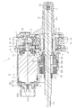
- FIG. 1 is a sectional view of an electric actuator according to one embodiment of the present invention. First, the overall configuration and operation of the electric actuator according to the present embodiment will be described with reference to FIG.
- An electric actuator 1 shown in FIG. 1 includes a motor unit 2 having an electric motor 5, a driving force transmitting mechanism 3 for transmitting a rotational movement of the electric motor 5, and a movement converting mechanism for converting the rotational movement of the electric motor 5 into a linear movement.
- 4 is the main configuration.
- the motor unit 2 includes the electric motor 5, a pair of bus bars 70 as a conductive member for supplying electric power to the electric motor 5, and a motor case 60 that houses the electric motor 5, the bus bar 70, and the like.
- an inexpensive (with brush) DC motor is used as the electric motor 5, but another motor such as a brushless motor may be used.
- the motor case 60 here is configured separately from a case (housing) of the electric motor 5 itself, and a case (a case of an electric actuator that houses the entire electric motor 5 having its own case). Actuator case).
- the motor case 60 includes a cylindrical main body 61 serving as a first case division body that accommodates most of the electric motor 5, and a second case division fixed to one end (the left end in FIG. 1) of the main body 61. And a lid-shaped cap portion 62 as a body.
- Each bus bar 70 is formed by bending a metal plate member into a predetermined shape, and is held by a resin holder 71, respectively. Further, each bus bar 70 is connected by welding to a motor terminal 5 d (see FIG. 2) of the electric motor 5 in a state where the holder 71 is fixed to an end (the left end in FIG. 1) of the electric motor 5. ing.
- the cap portion 62 is provided with a cylindrical connector portion 62a that protrudes in the axial direction, and the inner peripheral side of the connector portion 62a has a distal end portion of each bus bar 70 (the side opposite to the side connected to the motor terminal 5d). End). By connecting the other end of a power line extending from a power source (not shown) to the tip of the bus bar 70, power can be supplied from the power source to the electric motor 5.
- the driving force transmission mechanism 3 includes a drive gear 8 on the drive side and a driven gear 9 on the driven side that meshes with the drive gear 8.
- the drive gear 8 and the driven gear 9 are housed in a gear case 10.
- the drive gear 8 is a small-diameter gear having a smaller number of teeth than the driven gear 9, and is attached to the rotating shaft 5 a of the electric motor 5 so as to rotate integrally therewith.
- the driven gear 9 is a large-diameter gear having more teeth than the drive gear 8, and is attached to a nut 17, which will be described later, constituting the motion conversion mechanism 4 so as to rotate integrally therewith. ing.
- the drive gear 8 is rotatably supported by two bearings 11 and 12 at both ends in the axial direction.
- One of the two bearings 11 and 12 (the left side in FIG. 1) is held by being fitted into a cylindrical bearing holding member 13 fixed to an end of the electric motor 5, and the other (see FIG. 1).
- the bearing 12 (on the right side in FIG. 1) is held by being fitted into the gear case 10.
- the driven gear 9 is rotatably supported together with the nut 17 by double-row bearings 14 provided on the outer peripheral surface of the nut 17.
- the double-row bearings 14 are housed in a cylindrical sleeve 15 provided in the gear case 10, and movement in the axial direction is restricted by a retaining ring 16 mounted on the inner peripheral surface of the sleeve 15.
- the drive gear 8 rotates integrally with the rotating shaft 5a, and the driven gear 9 rotates in conjunction with this.
- the rotation is reduced and the rotational torque is increased.
- the drive gear 8 and the driven gear 9 may be constituted by gears having the same number of teeth, and the rotational motion from the electric motor 5 may be transmitted without deceleration.
- the motion conversion mechanism 4 is a ball screw mechanism having a nut 17 as a rotating member, a screw shaft 18 as a direct acting member, and a number of balls 19.
- Helical grooves are formed on the inner peripheral surface of the nut 17 and the outer peripheral surface of the screw shaft 18, respectively, and a ball 19 is rotatably accommodated between these spiral grooves.
- the nut 17 is provided with a circulation member (not shown), and the circulation member causes the ball 19 to circulate along the spiral groove.
- the screw shaft 18 is inserted through the inner periphery of the nut 17 and is arranged in parallel with the rotating shaft 5 a of the electric motor 5.
- a connection hole 18a is provided at the front end (left end in FIG. 1) of the screw shaft 18.
- a fastener such as a bolt
- the screw shaft 18 and the operation target are illustrated.
- the corresponding part of the used equipment is not connected.
- the rear end of the screw shaft 18 (the end opposite to the end on the operation target side) is covered with a screw shaft case 20.
- the screw shaft case 20 is fixed to the gear case 10 on the side opposite to the side where the motor case 60 is fixed.
- a rotation preventing pin 21 is provided as a rotation restricting member for restricting the rotation of the screw shaft 18.
- the detent pin 21 is attached to the screw shaft 18 in a direction orthogonal or intersecting with the axial direction.
- Guide rollers 22 are rotatably attached to both ends of the rotation preventing pins 21 projecting from the rear end of the screw shaft 18 in the radial direction.
- Each guide roller 22 is inserted into a pair of guide grooves 20 a provided in the screw shaft case 20 and extending in the axial direction. As the guide roller 22 moves in the axial direction along the guide groove 20a, the screw shaft 18 moves forward or backward in the axial direction without rotating in the circumferential direction.
- the boot 23 includes a small-diameter end portion 23a, a large-diameter end portion 23b, and a bellows portion 23c connecting and connecting them to expand and contract in the axial direction.
- the small-diameter end 23a is fixed to the outer peripheral surface of the screw shaft 18, and the large-diameter end 23b is fixed to the outer peripheral surface of a tubular boot mounting member 24 attached to the boot cover 25.
- the boot cover 25 is disposed so as to cover the outside of the boot 23, and is integrally formed with the main body 61 of the motor case 60.
- a ventilation filter 26 is provided in the screw shaft case 20.
- the ventilation filter 26 communicates with the internal space of the boot 23 through the inside of the electric actuator 1, and when the boot 23 expands and contracts, air flows in or out through the ventilation filter 26, thereby suppressing deformation of the bellows portion 23 c.
- a magnet 27 serving as a sensor target for detecting the axial position of the screw shaft 18 is provided on the outer peripheral surface of the screw shaft 18.
- a stroke sensor (not shown) is provided on the outer periphery of the motor case 60. When the screw shaft 18 moves forward or backward, the stroke sensor detects a change in the magnetic field (for example, the direction and strength of the magnetic flux density) of the magnet 27 that moves with the screw shaft 18, so that the axial position of the magnet 27, and thus the screw shaft 18 axial positions are detected.
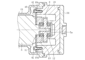
- a plate-like stay 40 as a support member is fixed to two end faces of the electric motor 5 on the side where the rotating shaft 5 a protrudes.
- a hole 40a is provided in the center of the stay 40, and two bolts 41 are provided on the stay 40 in a state where the rotary shaft 5a of the electric motor 5 is inserted through the hole 40a.
- the stay 40 is fixed to the end face of the electric motor 5 by screwing into the screw hole 5b provided on the end face of the electric motor 5 through the bolt insertion hole 40b.
- the stay 40 is provided with bolt insertion holes 40c through which another two bolts 42 are inserted, and the bolts 42 are inserted into these bolt insertion holes 40c, and as shown in FIG.
- the stay 40 is fixed to the gear case 10 by screwing it into the screw hole 10 a provided in the gear case 10. Thereby, the electric motor 5 is fixed to the gear case 10 via the stay 40.
- the electric motor 5 is fixed to the gear case 10 via the stay 40 at one axial end thereof.
- the other end of the electric motor 5 in the axial direction is not fastened to the motor case 60 by bolts or the like. If there is no support for the electric motor 5 at the other end side (hereinafter, referred to as “anti-fixed end side”), since the electric motor 5 is cantilevered, vibration from outside (for example, There is a problem in applying an electric actuator in a vibration environment exposed to vibration from an engine or vibration generated during running of a vehicle.
- the deflection of the electric motor 5 tends to increase particularly at a position apart from the fixed end of the electric motor 5 (opposite the fixed end).
- the welded portion between the motor terminal 5d and the bus bar 70 is damaged due to the vibration. For example, there is a possibility that these connection states cannot be maintained satisfactorily.
- the holder 71 fixed to the electric motor 5 collides with the inner surface of the motor case 60 before the electric motor 5 when the deflection occurs on the side opposite to the fixed end of the electric motor 5, the collision While the movement (shake) of the holder 71 is regulated by the force (force in the direction opposite to the direction of the shake), the non-fixed end of the electric motor 5 is further moved toward the inner surface of the motor case 60 by the inertial movement due to the shake. Because of the movement, movements in opposite directions occur between the holder 71 and the electric motor 5. In such a case, the opposing movement of the holder 71 and the electric motor 5 applies a load in a direction in which the motor terminal 5d and the bus bar 70 are separated from each other at a welding location. When such a load is repeatedly applied to the welded portion, the welded portion is damaged due to fatigue or the like, and the electric actuator 1 breaks down (control becomes impossible).
- the following measures are taken in order to highly suppress the vibration on the side opposite to the fixed end of the electric motor 5.
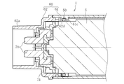
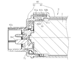
- FIG. 4 is a cross-sectional view of the electric motor on the side opposite to the fixed end and its peripheral portion.
- the outer peripheral surface of the electric motor 5 on the side opposite to the fixed end is connected to the motor case in order to suppress the vibration of the electric motor 5 on the side opposite to the fixed end.
- An O-ring 50 as an elastic member is provided between the main body 60 and the inner peripheral surface of the main body 61.
- the O-ring 50 is held between the electric motor 5 and the main body 61 of the motor case 60 in a state sandwiched in the radial direction.
- the O-ring 50 is provided to the electric motor 5 by a convex position regulating portion 61 c provided on the inner peripheral surface of the main body 61 and an end surface 62 d of the cap portion 62 fitted on the inner peripheral of the main body 61. Axial movement is restricted.
- a plurality of convex position restricting portions 61c extending in the circumferential direction are provided on the inner peripheral surface of the main body 61.
- the position restricting portions 61c are provided intermittently in the circumferential direction, but may be annular position restricting portions 61c provided continuously in the circumferential direction.
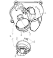
- the cap portion 62 is provided with a pair of claw-shaped engaging portions 62b at positions symmetrical with each other by 180 °.
- the main body 61 is provided with a pair of introduction portions 61a into which the engagement portions 62b are introduced.
- an engaged portion 61b capable of engaging with the engaging portion 62b is provided in the introduction portion 61a.
- the engagement structure between the engagement portion 62b and the engaged portion 61b is a so-called snap-fit type engagement structure.
- the end face 62d of the cap part 62 assembled in this manner faces the O-ring 50 mounted in the main body part 61, so that the O face between the end face 62d of the cap part 62 and the position regulating part 61c.
- the ring 50 is held.
- the end face 62d of the cap portion 62 and the position restricting portion 61c may be in a state of being in contact with the O-ring 50 or may be in a non-contact state.
- the O-ring 50 is restricted from moving in the axial direction of the electric motor 5 by the end face 62d of the cap portion 62 and the position restricting portion 61c.
- the O-ring 50 as the elastic member is formed between the outer peripheral surface on the side opposite to the fixed end of the electric motor 5 and the inner peripheral surface of the main body 61 of the motor case 60.
- the non-fixed end side of the electric motor 5 is elastically supported by the O-ring 50. That is, in the present embodiment, the non-fixed end of the electric motor 5, the holder 71 fixed to the non-fixed end, and the bus bar 70 held by the holder 71 are connected to the motor case 60.
- the electric motor 5 is not fixed to the motor case 60 via the O-ring 50, so that the electric motor 5 is elastic. Supported by Thus, even if a run-out occurs on the side opposite to the fixed end of the electric motor 5, the run-out is absorbed by the O-ring 50, thereby suppressing the run-out and preventing the collision of the holder 71 with the inner surface of the motor case 60. Can be avoided. Alternatively, even if the holder 71 collides with the inner surface of the motor case 60, the impact due to the collision can be suppressed. As a result, the load at the welding point between the motor terminal 5d and the bus bar 70 due to the collision can be reduced, and damage to the welding point can be prevented.
- the vibration suppressed by the O-ring 50 is not limited to the vibration in the radial direction of the electric motor 5, and the vibration in any other direction can be suppressed. That is, due to the frictional force of the O-ring 50 generated between the electric motor 5 and the motor case 60 and the elastic force acting in various directions of the O-ring 50, the vibration in any direction crossing the radial direction of the electric motor 5 is also reduced. It is possible to suppress.
- the run-out on the side opposite to the fixed end of the electric motor 5 can be suppressed to a high degree, so that the connection state between the motor terminal 5d and the bus bar 70 can be maintained even under a severe vibration environment. It is possible to provide a highly reliable electric actuator that can be maintained well.
- the axial movement of the O-ring 50 is regulated by the end surface 62d of the cap portion 62 and the position regulating portion 61c of the main body 61, so that the O-ring 50 is not fixed to the electric motor 5 in a reverse direction.
- the position can be held at the end side. Accordingly, it is possible to prevent the O-ring 50 from moving in the axial direction of the electric motor 5 and falling off due to vibration from the outside, and to prevent the O-ring 50 from moving toward the fixed end of the electric motor 5.
- the intended function of the ring 50 (shake suppression on the side opposite to the fixed end of the electric motor 5) can be reliably exerted over a long period of time.
- a convex position regulating portion is provided on the inner peripheral surface of the cap portion 62, and the axial movement of the O-ring 50 is regulated by the position regulating portion and the end surface of the main body 61. It is also possible to configure.
- the O-ring 50 is preferably made of a heat-resistant material (for example, fluorine rubber (FKM) or the like) because the temperature of the electric motor 5 may become high when the electric actuator 1 operates.
- the elastic member is not limited to the O-ring, and any other elastic member may be used as long as the vibration of the electric motor can be suppressed.
- FIGS. 7 to 12 other embodiments of the present invention will be described, mainly regarding portions different from the above-described embodiment and portions not described.
- members and components having the same configurations as those of the above-described embodiment are denoted by the same reference numerals as those in FIGS. 1 to 6, and the description thereof is partially omitted.
- the electric actuator 1 in order to suppress the run-out on the non-fixed end side (the end side not fastened to the motor case 60) of the electric motor 5.
- a rubber O-ring 38 as a second elastic member different from the O-ring 50 is provided between the holder 71 for holding the bus bar 70 and the cap 62 of the motor case 60 in the axial direction of the electric motor 5.
- the O-ring 50 as the first elastic member is provided between the outer peripheral surface of the electric motor 5 on the side opposite to the fixed end and the inner peripheral surface of the motor case 60.
- the O-ring 50 is not shown in FIGS. 7, 8 and 12.
- the holder 71 has a tubular portion 71a and a flange portion 71b protruding outside the outer peripheral surface of the tubular portion 71a.
- the holder 71 is integrated with the bus bar 70 by insert molding. Rectangular recesses 71c are formed in the flange portion 71b at positions that are symmetrical with each other by 180 °, and are arranged so that one end 70a of each bus bar 70 is exposed in each recess 71c.
- the other end 70b of each bus bar 70 is disposed so as to protrude in the axial direction from the space partitioned into the two cylindrical portions 71a.
- the flange 71b is provided with a pair of convex fitting portions 71d at locations different in phase by 90 ° from the concave portions 71c.
- the convex fitting portion 71 d of the holder portion 71 is axially fitted to the concave fitting portion 5 c of the electric motor 5, the holder portion 71 Fixed to the fixed end. Then, in this state, one end 70a of each bus bar 70 is welded to the motor terminal 5d, so that they are electrically connected.
- an axial mounting surface 71 e on which the O-ring 38 is mounted is disposed along the axial direction of the cylindrical portion 71 a. , Is formed in a direction intersecting with the axial direction of the cylindrical portion 71a, and a stepped portion formed by an abutting surface 71f against which the O-ring 38 is abutted is formed.
- the O-ring 38 is mounted on the outer periphery of the mounting surface 71e, and is positioned in the axial direction by being abutted against the abutting surface 71f.
- the cap portion 62 is provided with a pair of claw-shaped engaging portions 62b at positions symmetrical with each other by 180 °.
- the main body 61 is provided with a pair of introduction portions 61a into which the engagement portions 62b are introduced.
- an engaging portion 62b and a to-be-engaged portion 61b which are snap-fit type engaging structures, are provided in the introduction portion 61a, as in the above-described embodiment.
- an annular protruding wall portion 62 c that is continuous in the circumferential direction is provided on the inner peripheral surface of the connector portion 62 a of the cap portion 62.
- the annular protruding wall portion 62c cooperates with the abutment surface 71f provided on the holder portion 71 to form the O-ring 38 in a state where the cap portion 62 is attached to the main body portion 61. It is the part that is held between the two. That is, while the O-ring 38 is mounted on the mounting surface 71 e of the holder 71, the holder 71 is fixed to the electric motor 5, and the electric motor 5 is housed in the main body 61, the cap is closed.
- the O-ring 38 When the portion 62 is attached to the main body 61, the O-ring 38 is pushed in the axial direction of the electric motor 5 by the projecting wall portion 62 c of the cap portion 62, and the O-ring 38 is pressed against the abutting surface 71 f of the holder portion 71. Can be As a result, the O-ring 38 is held between the projecting wall portion 62c and the abutting surface 71f while being compressed in the axial direction of the electric motor 5.
- the O-ring 38 as the second elastic member is provided between the abutting surface 71f of the holder 71 and the protruding wall 62c of the cap 62.
- the non-fixed end side of the electric motor 5 is elastically supported by the O-ring 38. That is, in the present embodiment, the non-fixed end of the electric motor 5, the holder 71 fixed to the non-fixed end, and the bus bar 70 held by the holder 71 are connected to the motor case 60.
- the electric motor 5 is not fixed because the holder 71 is in contact with the motor case 60 via the O-ring 38.
- the end side is elastically supported. Accordingly, even if a run-out occurs on the side opposite to the fixed end of the electric motor 5, the run-out is absorbed by the O-ring 38, thereby suppressing the run-out and preventing the collision of the holder 71 with the inner surface of the motor case 60. Can be avoided. Alternatively, even if the holder 71 collides with the inner surface of the motor case 60, the impact due to the collision can be suppressed. As a result, the load at the welding point between the motor terminal 5d and the bus bar 70 due to the collision can be reduced, and damage to the welding point can be prevented.
- the axial rebound of the electric motor 5 by the O-ring 38 causes the axial vibration of the electric motor 5 (the axial direction of the vibration).
- the vibration suppressed by the O-ring 38 is not limited to the vibration in the axial direction of the electric motor 5, and the vibration in any other direction can be suppressed. That is, due to the frictional force of the O-ring 38 generated between the holder 71 and the cap 62 and the elastic force acting in various directions of the O-ring 38, the vibration in an arbitrary direction intersecting with the axial direction of the electric motor 5 is also reduced. It is possible to suppress.
- the run-out on the side opposite to the fixed end of the electric motor 5 can be suppressed to a high degree, so that the connection state between the motor terminal 5d and the bus bar 70 can be maintained even under a severe vibration environment. It is possible to provide a highly reliable electric actuator that can be maintained well.
- the engaging portion 62b of the cap portion 62 and the main body portion 61 are provided. Axial play with the engaged portion 61b can be eliminated. That is, since the O-ring 38 generates the above-described elastic repulsive force in the axial direction, the elastic repulsive force urges the engaging portion 62b in the direction of engagement with the engaged portion 61b. The joining portion 62b is securely engaged with the engaged portion 61b. Thereby, the assemblability of the cap part 62 to the main body part 61 is improved.
- the O-ring 38 is adopted as the second elastic member, and the O-ring 38 is mounted on the outer periphery of the cylindrical portion 71a, so that the second elastic member can be easily mounted.
- the two elastic members are not limited to the O-ring, and other elastic members may be used as long as the vibration of the electric motor can be suppressed.
- the case of the electric actuator 1 includes the motor case 60 including the main body 61 and the cap 62, the gear case 10, the screw shaft case 20, and the boot cover 25.
- the structure of the case is not limited to the above embodiment.
- the shape and division structure of the case can be appropriately changed according to the change of the specification of the internal structure of the electric actuator and the assembling property.
Landscapes
- Engineering & Computer Science (AREA)
- Power Engineering (AREA)
- General Engineering & Computer Science (AREA)
- Mechanical Engineering (AREA)
- Motor Or Generator Frames (AREA)
- Connection Of Motors, Electrical Generators, Mechanical Devices, And The Like (AREA)
Abstract
L'invention porte sur un actionneur électrique comprenant un carter, un moteur électrique 5 intégré dans le carter, et un mécanisme de conversion de mouvement 4 pour convertir un mouvement de rotation du moteur électrique 5 en un mouvement linéaire, le moteur électrique 5 étant fixé au carter (carter d'engrenage 10) à une extrémité du moteur électrique 5 dans la direction axiale de celui-ci ; à l'autre extrémité du moteur électrique 5, opposée à l'extrémité qui est fixée au carter (carter d'engrenage 10), un premier élément élastique 50 est disposé entre la surface périphérique externe du moteur électrique 5 et la surface périphérique interne du carter (carter moteur 60).
Priority Applications (2)
| Application Number | Priority Date | Filing Date | Title |
|---|---|---|---|
| CA3103198A CA3103198A1 (fr) | 2018-06-29 | 2019-06-25 | Actionneur electrique |
| US16/973,882 US11804751B2 (en) | 2018-06-29 | 2019-06-25 | Electric actuator including a holder that holds a conductive member and an elastic member that is interposed and held between the holder and a case |
Applications Claiming Priority (4)
| Application Number | Priority Date | Filing Date | Title |
|---|---|---|---|
| JP2018124582A JP7195069B2 (ja) | 2018-06-29 | 2018-06-29 | 電動アクチュエータ |
| JP2018124584A JP7224120B2 (ja) | 2018-06-29 | 2018-06-29 | 電動アクチュエータ |
| JP2018-124584 | 2018-06-29 | ||
| JP2018-124582 | 2018-06-29 |
Publications (1)
| Publication Number | Publication Date |
|---|---|
| WO2020004377A1 true WO2020004377A1 (fr) | 2020-01-02 |
Family
ID=68986667
Family Applications (1)
| Application Number | Title | Priority Date | Filing Date |
|---|---|---|---|
| PCT/JP2019/025116 Ceased WO2020004377A1 (fr) | 2018-06-29 | 2019-06-25 | Actionneur électrique |
Country Status (3)
| Country | Link |
|---|---|
| US (1) | US11804751B2 (fr) |
| CA (1) | CA3103198A1 (fr) |
| WO (1) | WO2020004377A1 (fr) |
Families Citing this family (2)
| Publication number | Priority date | Publication date | Assignee | Title |
|---|---|---|---|---|
| JP2023046772A (ja) | 2021-09-24 | 2023-04-05 | Ntn株式会社 | 電動アクチュエータ |
| FR3143079B1 (fr) * | 2022-12-07 | 2024-10-25 | Valeo Systemes De Controle Moteur | Actionneur électromécanique |
Citations (2)
| Publication number | Priority date | Publication date | Assignee | Title |
|---|---|---|---|---|
| JPS56141489U (fr) * | 1980-03-25 | 1981-10-26 | ||
| JPH09191606A (ja) * | 1996-01-09 | 1997-07-22 | Aichi Electric Co Ltd | 電動アクチュエータ |
Family Cites Families (16)
| Publication number | Priority date | Publication date | Assignee | Title |
|---|---|---|---|---|
| JPS56141489A (en) | 1980-04-02 | 1981-11-05 | Takemasa Hashimoto | Bendable tube member |
| IT1232034B (it) * | 1989-03-09 | 1992-01-23 | Rgb Spa | Attuatore lineare elettromeccanico |
| JP4018367B2 (ja) | 2001-10-26 | 2007-12-05 | サンデン株式会社 | 電動式圧縮機 |
| CN1922418B (zh) * | 2004-02-24 | 2010-08-04 | 利纳克有限公司 | 具有过载离合器的线性执行机构 |
| JP5291285B2 (ja) | 2006-07-11 | 2013-09-18 | サンデン株式会社 | 電動圧縮機の密封端子装置 |
| CN101509540B (zh) * | 2008-02-14 | 2011-06-15 | 德昌电机(深圳)有限公司 | 动力传输装置 |
| DE102008044980B4 (de) * | 2008-08-29 | 2013-04-25 | Hs Products Engineering Gmbh | Antriebssystem |
| DE102010020912A1 (de) * | 2010-05-19 | 2011-11-24 | Eppendorf Ag | Schwingungsdämpfung einer elektrischen Vorrichtung |
| KR20130035322A (ko) * | 2011-09-30 | 2013-04-09 | 주식회사 모아텍 | 소음 방지 기능을 갖는 스텝 엑츄에이터 |
| JP5942945B2 (ja) * | 2013-08-27 | 2016-06-29 | 株式会社アドヴィックス | 電動パーキングブレーキ用駆動装置および電動パーキングブレーキ装置 |
| JP6247482B2 (ja) | 2013-09-17 | 2017-12-13 | Ntn株式会社 | 歯車およびこれを備えた電動アクチュエータ |
| TR201819469T4 (tr) * | 2014-07-29 | 2019-01-21 | Linak As | Doğrusal aktüatör. |
| JP6732482B2 (ja) * | 2016-03-10 | 2020-07-29 | シロキ工業株式会社 | モータユニット |
| JP6752687B2 (ja) | 2016-10-31 | 2020-09-09 | Ntn株式会社 | 電動アクチュエータ |
| JP2018074790A (ja) | 2016-10-31 | 2018-05-10 | Ntn株式会社 | 電動アクチュエータ |
| JP7146369B2 (ja) * | 2017-03-29 | 2022-10-04 | Ntn株式会社 | 電動アクチュエータおよび電動アクチュエータの製造方法 |
-
2019
- 2019-06-25 WO PCT/JP2019/025116 patent/WO2020004377A1/fr not_active Ceased
- 2019-06-25 US US16/973,882 patent/US11804751B2/en active Active
- 2019-06-25 CA CA3103198A patent/CA3103198A1/fr active Pending
Patent Citations (2)
| Publication number | Priority date | Publication date | Assignee | Title |
|---|---|---|---|---|
| JPS56141489U (fr) * | 1980-03-25 | 1981-10-26 | ||
| JPH09191606A (ja) * | 1996-01-09 | 1997-07-22 | Aichi Electric Co Ltd | 電動アクチュエータ |
Also Published As
| Publication number | Publication date |
|---|---|
| US11804751B2 (en) | 2023-10-31 |
| CA3103198A1 (fr) | 2020-01-02 |
| US20210265892A1 (en) | 2021-08-26 |
Similar Documents
| Publication | Publication Date | Title |
|---|---|---|
| US8893847B2 (en) | Electric power steering system | |
| CN109923767B (zh) | 电动致动器 | |
| KR102281681B1 (ko) | 자동차의 감속기 | |
| JP6599668B2 (ja) | アクチュエータ | |
| US11428300B2 (en) | Electric actuator | |
| JP2020005453A (ja) | 電動アクチュエータ | |
| JP5618146B2 (ja) | 電動パワーステアリング装置 | |
| US11804751B2 (en) | Electric actuator including a holder that holds a conductive member and an elastic member that is interposed and held between the holder and a case | |
| KR102837953B1 (ko) | 전동 액츄에이터 | |
| JP2020005454A (ja) | 電動アクチュエータ | |
| WO2019059355A1 (fr) | Actionneur électrique | |
| WO2022064961A1 (fr) | Actionneur électrique | |
| JP6254005B2 (ja) | 伸縮アクチュエータ | |
| CN113153901A (zh) | 挠性轴承和减速器 | |
| JP2022053020A (ja) | 電動アクチュエータ | |
| JP2021025642A (ja) | 電動アクチュエータ | |
| JP4452981B2 (ja) | ボールねじ機構 | |
| JP2007232023A (ja) | 電動アクチュエータ | |
| JP7224145B2 (ja) | 電動アクチュエータ | |
| JP2007303514A (ja) | 電動リニアアクチュエータ | |
| JP2016043791A (ja) | 伸縮アクチュエータ | |
| US9989142B2 (en) | Linear actuator | |
| JP2008069793A (ja) | 電動リニアアクチュエータ | |
| JP2024034794A (ja) | ボールねじ装置 | |
| WO2021020075A1 (fr) | Actionneur électrique |
Legal Events
| Date | Code | Title | Description |
|---|---|---|---|
| 121 | Ep: the epo has been informed by wipo that ep was designated in this application |
Ref document number: 19825178 Country of ref document: EP Kind code of ref document: A1 |
|
| ENP | Entry into the national phase |
Ref document number: 3103198 Country of ref document: CA |
|
| NENP | Non-entry into the national phase |
Ref country code: DE |
|
| 122 | Ep: pct application non-entry in european phase |
Ref document number: 19825178 Country of ref document: EP Kind code of ref document: A1 |