WO2020004407A1 - Dispositif de transfert thermique - Google Patents
Dispositif de transfert thermique Download PDFInfo
- Publication number
- WO2020004407A1 WO2020004407A1 PCT/JP2019/025210 JP2019025210W WO2020004407A1 WO 2020004407 A1 WO2020004407 A1 WO 2020004407A1 JP 2019025210 W JP2019025210 W JP 2019025210W WO 2020004407 A1 WO2020004407 A1 WO 2020004407A1
- Authority
- WO
- WIPO (PCT)
- Prior art keywords
- layer
- parts
- thermal transfer
- ink
- resin
- Prior art date
- Legal status (The legal status is an assumption and is not a legal conclusion. Google has not performed a legal analysis and makes no representation as to the accuracy of the status listed.)
- Ceased
Links
Images
Classifications
-
- B—PERFORMING OPERATIONS; TRANSPORTING
- B41—PRINTING; LINING MACHINES; TYPEWRITERS; STAMPS
- B41M—PRINTING, DUPLICATING, MARKING, OR COPYING PROCESSES; COLOUR PRINTING
- B41M5/00—Duplicating or marking methods; Sheet materials for use therein
- B41M5/26—Thermography ; Marking by high energetic means, e.g. laser otherwise than by burning, and characterised by the material used
- B41M5/382—Contact thermal transfer or sublimation processes
- B41M5/38264—Overprinting of thermal transfer images
-
- B—PERFORMING OPERATIONS; TRANSPORTING
- B41—PRINTING; LINING MACHINES; TYPEWRITERS; STAMPS
- B41M—PRINTING, DUPLICATING, MARKING, OR COPYING PROCESSES; COLOUR PRINTING
- B41M5/00—Duplicating or marking methods; Sheet materials for use therein
- B41M5/26—Thermography ; Marking by high energetic means, e.g. laser otherwise than by burning, and characterised by the material used
- B41M5/382—Contact thermal transfer or sublimation processes
-
- B—PERFORMING OPERATIONS; TRANSPORTING
- B41—PRINTING; LINING MACHINES; TYPEWRITERS; STAMPS
- B41M—PRINTING, DUPLICATING, MARKING, OR COPYING PROCESSES; COLOUR PRINTING
- B41M5/00—Duplicating or marking methods; Sheet materials for use therein
- B41M5/26—Thermography ; Marking by high energetic means, e.g. laser otherwise than by burning, and characterised by the material used
- B41M5/382—Contact thermal transfer or sublimation processes
- B41M5/38207—Contact thermal transfer or sublimation processes characterised by aspects not provided for in groups B41M5/385 - B41M5/395
- B41M5/38214—Structural details, e.g. multilayer systems
-
- B—PERFORMING OPERATIONS; TRANSPORTING
- B41—PRINTING; LINING MACHINES; TYPEWRITERS; STAMPS
- B41M—PRINTING, DUPLICATING, MARKING, OR COPYING PROCESSES; COLOUR PRINTING
- B41M5/00—Duplicating or marking methods; Sheet materials for use therein
- B41M5/26—Thermography ; Marking by high energetic means, e.g. laser otherwise than by burning, and characterised by the material used
- B41M5/382—Contact thermal transfer or sublimation processes
- B41M5/385—Contact thermal transfer or sublimation processes characterised by the transferable dyes or pigments
-
- B—PERFORMING OPERATIONS; TRANSPORTING
- B41—PRINTING; LINING MACHINES; TYPEWRITERS; STAMPS
- B41M—PRINTING, DUPLICATING, MARKING, OR COPYING PROCESSES; COLOUR PRINTING
- B41M5/00—Duplicating or marking methods; Sheet materials for use therein
- B41M5/26—Thermography ; Marking by high energetic means, e.g. laser otherwise than by burning, and characterised by the material used
- B41M5/40—Thermography ; Marking by high energetic means, e.g. laser otherwise than by burning, and characterised by the material used characterised by the base backcoat, intermediate, or covering layers, e.g. for thermal transfer dye-donor or dye-receiver sheets; Heat, radiation filtering or absorbing means or layers; combined with other image registration layers or compositions; Special originals for reproduction by thermography
- B41M5/41—Base layers supports or substrates
-
- B—PERFORMING OPERATIONS; TRANSPORTING
- B41—PRINTING; LINING MACHINES; TYPEWRITERS; STAMPS
- B41M—PRINTING, DUPLICATING, MARKING, OR COPYING PROCESSES; COLOUR PRINTING
- B41M5/00—Duplicating or marking methods; Sheet materials for use therein
- B41M5/26—Thermography ; Marking by high energetic means, e.g. laser otherwise than by burning, and characterised by the material used
- B41M5/40—Thermography ; Marking by high energetic means, e.g. laser otherwise than by burning, and characterised by the material used characterised by the base backcoat, intermediate, or covering layers, e.g. for thermal transfer dye-donor or dye-receiver sheets; Heat, radiation filtering or absorbing means or layers; combined with other image registration layers or compositions; Special originals for reproduction by thermography
- B41M5/42—Intermediate, backcoat, or covering layers
- B41M5/44—Intermediate, backcoat, or covering layers characterised by the macromolecular compounds
-
- B—PERFORMING OPERATIONS; TRANSPORTING
- B41—PRINTING; LINING MACHINES; TYPEWRITERS; STAMPS
- B41M—PRINTING, DUPLICATING, MARKING, OR COPYING PROCESSES; COLOUR PRINTING
- B41M2205/00—Printing methods or features related to printing methods; Location or type of the layers
- B41M2205/02—Dye diffusion thermal transfer printing (D2T2)
-
- B—PERFORMING OPERATIONS; TRANSPORTING
- B41—PRINTING; LINING MACHINES; TYPEWRITERS; STAMPS
- B41M—PRINTING, DUPLICATING, MARKING, OR COPYING PROCESSES; COLOUR PRINTING
- B41M2205/00—Printing methods or features related to printing methods; Location or type of the layers
- B41M2205/30—Thermal donors, e.g. thermal ribbons
-
- B—PERFORMING OPERATIONS; TRANSPORTING
- B41—PRINTING; LINING MACHINES; TYPEWRITERS; STAMPS
- B41M—PRINTING, DUPLICATING, MARKING, OR COPYING PROCESSES; COLOUR PRINTING
- B41M2205/00—Printing methods or features related to printing methods; Location or type of the layers
- B41M2205/38—Intermediate layers; Layers between substrate and imaging layer
-
- B—PERFORMING OPERATIONS; TRANSPORTING
- B41—PRINTING; LINING MACHINES; TYPEWRITERS; STAMPS
- B41M—PRINTING, DUPLICATING, MARKING, OR COPYING PROCESSES; COLOUR PRINTING
- B41M2205/00—Printing methods or features related to printing methods; Location or type of the layers
- B41M2205/40—Cover layers; Layers separated from substrate by imaging layer; Protective layers; Layers applied before imaging
Definitions
- the present invention relates to a thermal transfer ribbon.
- This application claims the priority of Japanese Patent Application No. 2018-124785 filed on June 29, 2018, and uses the contents thereof.
- the thermal transfer ribbon is an ink ribbon used for a thermal transfer type printer, and is also called a thermal ribbon.
- a general thermal transfer ribbon has a configuration in which a thermal transferable ink layer is provided on one surface of a substrate, and a heat-resistant lubricating layer (backcoat layer) is provided on the other surface of the substrate.
- the ink in the thermal transfer ink layer is sublimated (sublimation transfer method) or melted (melt transfer method) by heat generated in the thermal head of the printer, and is transferred to the thermal transfer image receiving sheet side.
- the sublimation transfer method can be used in a wide range of fields, such as self-printing of digital cameras, cards such as identification cards, and amusement output products, because various images can be easily formed in full color in conjunction with the enhancement of printer functions. I have. As the range of use has expanded, there has been an increasing demand for improving the durability of a printed matter obtained by the sublimation transfer method.
- Patent Documents 1 and 2 disclose that a release layer and a release layer are provided on a base sheet of a thermal transfer ribbon, and a resin layer serving as a protective layer is provided thereon.
- Patent Document 3 discloses a method in which an acrylic-silica hybrid resin having no tack at room temperature is used to form a thermal transferable overcoat layer, and after transferring the thermal transferable overcoat layer on a transfer target, ionization is applied to a transfer portion. Irradiation and curing are described.
- Patent Document 4 describes a protective layer using the reactivity of epoxy.
- Patent Document 3 needs to incorporate a device for irradiating ionizing radiation into the printer, and there remains a problem from the viewpoint of reducing the size and cost of the printer.
- the protective layer material described in Patent Literature 4 has a pot life due to crosslinking by a reaction between an epoxy group and an amino group. If the cross-linking reaction has progressed before the application, the ink may gel, etc., and the appearance may be deteriorated. In order to prevent this, it is necessary to form the coating before the cross-linking reaction proceeds too much, and the manufacturing conditions are restricted.
- an object of the present invention is to provide a thermal transfer ribbon capable of suitably protecting a thermal transfer image with a protective layer while suppressing burrs and chipping.
- the present invention is a thermal transfer ribbon in which a dye layer and a transferable protective layer are repeatedly formed on one surface of a substrate.
- the transferable protective layer has a first layer formed on the base material and a second layer formed on the first layer.
- the first layer is composed of an acrylic resin (X) containing methyl methacrylate, an acrylic resin (Y) containing a styrene resin, and a polyester resin (Z).
- the weight average molecular weight of X is 120,000 or more.
- the mass ratio of X to Y is in the range of 1: 9 to 9: 1.
- the mass of Z is 1% or more and 3% or less of the total mass of X and Y.
- the thermal transfer ribbon of the present invention can suitably protect the thermal transfer image with the protective layer while suppressing burrs and chipping.
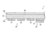
- FIG. 1 is a schematic sectional view of a thermal transfer ribbon according to one embodiment of the present invention.
- FIG. 1 is a schematic cross-sectional view showing a thermal transfer ribbon 1 of the present embodiment.
- the thermal transfer ribbon 1 includes a base material 10, a dye layer 20, a transferable protective layer 30, and a heat-resistant lubricating layer 40.
- the dye layer 20 and the transferable protective layer 30 are provided on the first surface 10 a of the substrate 10.
- the heat-resistant lubricating layer 40 is provided on the second surface 10b of the substrate 10 opposite to the first surface 10a.
- a plurality of pairs of the dye layer 20 and the transferable protective layer 30 are repeatedly formed in the longitudinal direction of the thermal transfer ribbon 1.
- plastic films can be used as the substrate 10.
- the material of the plastic film is not particularly limited, but polyester, polyethylene naphthalate, polystyrene, polysulfone, polyimide, polycarbonate, polypropylene, and the like are preferable in terms of high mechanical strength and smooth surface.
- PET polyethylene terephthalate
- the thickness of the substrate 10 is not particularly limited, but is, for example, about 1 to 50 ⁇ m.
- the dye layer 20 of the present embodiment has three colored layers of a yellow dye layer 21, a magenta dye layer 22, and a cyan dye layer 23.
- the number and arrangement order of the colored layers are not limited to the mode of the present embodiment, and can be set as appropriate.
- the base resin used for the dye layer 20 is preferably a polyvinyl butyral resin having a good balance of heat resistance, fastness, dyeing performance of the dye, and the like.
- the polyvinyl butyral resin may include a crosslinked structure.
- a urethane cross-linked structure can be formed by adding a polyol component (hydroxyl group) to a polyvinyl butyral resin, adding an isocyanate cross-linking agent, and reacting.
- the isocyanate crosslinking agent may be composed of a compound having at least one isocyanate group in the molecule. Examples include tolylene diisocyanate (TDI), hexamethylene diisocyanate (HDI), methylene diphenyl diisocyanate (MDI), and xylylene diisocyanate (XDI).
- a general sublimation dye used for a thermal transfer ribbon can be used.
- diarylmethane, triarylmethane, thiazole, methine, azomethane, xanthene, axazine, thiazine, azine, acridine, azo, spirodipyran, indolinospiropyran, fluoran, rhodamine Dactam type, anthraquinone type and the like can be mentioned.
- examples of yellow dyes used in the yellow dye layer 21 include CI Solvent Yellow 14, 16, 29, 30, 33, 56, 93, and CI Disperse Yellow 7, 33, 60. , 141, 201, 231 and the like.
- examples of the magenta dye used in the magenta dye layer 22 include CI Solvent Red 18, 19, 27, 143, and 182, CI Disperse Red 60, 73, 135, 167, and the like, and CI Disperse Violet. 13, 26, 31, 56 and the like.
- Examples of the cyan dye used for the cyan dye layer 23 include CI Solvent Blue 11, 36, 63 and 105, and CI Disperse Blue 24, 72, 154 and 354.
- Each layer of the dye layer 20 may contain a silicone release agent.
- the silicone release agent include an amino-modified silicone oil and an epoxy-modified silicone oil.
- the method for forming the dye layer 20 is not particularly limited. As an example, first, the above-described components are added to a solvent to prepare an ink for forming a dye layer. When the ink for forming a dye layer is applied onto the substrate 10 by gravure coating or the like and then dried, the dye layer 20 can be formed on the substrate 10.
- the solvent include methyl ethyl ketone, toluene, cyclohexanone, butyl cellosolve and the like.
- the thickness of each layer of the dye layer 20 is not particularly limited. For example, the thickness is about 0.5 to 2.0 ⁇ m, and may be appropriately set in consideration of the appearance of the print.
- the transferable protective layer 30 is a substantially transparent resin layer, and has a first layer 31 provided on the base material 10 and a second layer 32 formed on the first layer 31.
- the first layer 31 is composed mainly of the following three types of resins, X, Y and Z.
- Resin X Acrylic resin containing methyl methacrylate
- Resin Y Acrylic resin containing styrene resin
- Resin Z Polyester resin
- resin X, resin Y, and resin Z are simply referred to as X, Y, and Z, respectively. It may be called.
- the mass ratio between X and Y in the first layer 31 is in the range of 1: 9 to 9: 1.
- the transfer performance of the transferable protective layer 30 is improved, and the transfer layer is formed on the image receiving sheet by the dye layer 20.
- Methyl methacrylate has good plasticizer resistance performance, and styrene is a high refractive index material, so reflection at the interface between the print layer and the protective layer becomes highly reflective, and a print with high gloss is obtained.
- the styrene resin has a good affinity for the vinyl chloride resin used as the image receiving layer, in other words, the solubility parameter is close, thereby improving the overprint transfer performance of the transferable protective layer 30.
- the cold adhesion performance between the transferable protective layer 30 and the base material 10 is improved.
- burrs and chipping of the protective layer formed on the image receiving sheet are suitably suppressed. If the performance of the cold adhesion is improved, the transferable protective layer will not peel off from the substrate during the ribbon feeding operation performed during the initialization operation inside the printer, and the transferable protective layer will fall off the substrate by the time of thermal transfer. Can be transferred without. As a result, burrs and chipping can be suppressed.
- the resin Z is preferably an amorphous polyester.
- the weight average molecular weight Mw of the resin X is 120,000 or more. As shown in Examples, the inventors have found that among the resins X, those having a weight average molecular weight of 120,000 or more are excellent in the effect of suppressing burrs and chipping.
- Examples of the resin X used as the material of the first layer 31 include BR-88, BR-85, BR-84, and BR-82 of Dianal (registered trademark) series manufactured by Mitsubishi Chemical Corporation. Among them, BR-88, BR-85, BR-84 and the like are particularly preferable.
- the first layer 31 may contain various additives as long as the function is not impaired.
- the additive include an antistatic agent, a charge control agent, an ultraviolet absorber, a light stabilizer, an antioxidant, a fluorescent brightener, a filler, and the like.
- the thickness of the first layer 31 can be appropriately set, and may be, for example, about 0.3 to 3 ⁇ m.
- the second layer 32 is a layer which is brought into contact with and joined to the image receiving sheet and the printing material layer formed on the image receiving sheet.
- a resin that is melted by heat can be used.
- styrene resins such as polystyrene and poly ⁇ -methylstyrene
- acrylic resins such as polymethyl methacrylate and polyethyl acrylate
- polyvinyl chloride polyvinyl acetate, vinyl chloride-vinyl acetate copolymer
- polyvinyl butyral Synthetic resins such as vinyl resins such as polyvinyl acetal, polyester resins, polyamide resins, epoxy resins, polyurethane resins, petroleum resins, ionomers, ethylene-acrylic acid copolymers, ethylene-acrylic acid ester copolymers, nitrocellulose, and ethylcellulose
- Cellulose derivatives such as cellulose acetate propionate, rosin, rosin-
- the thickness of the second layer 32 can be appropriately set, and may be, for example, about 0.5 to 3.0 ⁇ m.
- the heat-resistant lubricating layer 40 suppresses heat sticking between the thermal head of the printer and the thermal transfer ribbon 1.
- the heat-resistant lubricating layer 40 contains a binder, a lubricant, an abrasive, and the like.
- thermoplastic resin containing a hydroxyl group examples include polyvinyl butyral, polyvinyl acetal, polyester polyol, acrylic polyol, polyether polyol, urethane polyol, and the like. Among them, acrylic polyols are preferred, and among them, those having a high molecular weight are particularly preferred.
- isocyanates polyvalent isocyanates can be used.
- a phosphate ester can be used.
- the phosphate ester may have a structure in which esterification is performed at one or two sites out of three phosphate groups per one molecule of phosphoric acid, for example.
- a monoester or diester of an alkylene oxide adduct of a saturated alcohol (eg, stearyl alcohol, lauryl alcohol, etc.) or an unsaturated alcohol (eg, oleyl alcohol, etc.) with phosphoric acid is preferred.
- ethylene oxide is preferable, and the number of addition is preferably from 1 to 20, more preferably from 1 to 8.
- the abrasive has a role of removing print residues generated from the heat-resistant lubricating layer 40 in contact with the thermal head of the printer or other layers of the thermal transfer ribbon 1.
- the abrasive for example, magnesium oxide can be used.
- the magnesium oxide those produced by a known method can be used. Examples of the known production method include a method in which magnesium carbonate, nitrate, hydroxide and the like are calcined and hydrolyzed, and a method in which magnesium is vapor-phase oxidized.
- oxides such as silica, clay minerals such as talc and kaolin, carbonates such as calcium carbonate and magnesium carbonate, hydroxides such as aluminum hydroxide and magnesium hydroxide, sulfates such as calcium sulfate, Inorganic fine particles such as graphite, nitrite, boron nitride, etc .; organic resin fine particles such as acrylic resin, fluororesin, silicone resin, phenol resin, acetal resin, polystyrene resin, nylon resin, etc .; and crosslinked resin fine particles obtained by reacting these with a crosslinker. , Can be used as an abrasive.
- the method for forming the heat-resistant lubricating layer 40 is not particularly limited. As an example, a method of preparing a mixture containing the above-described components, applying the mixture to one surface of the substrate 10, and then drying the mixture can be exemplified.
- the thickness of the heat-resistant lubricating layer 40 is not particularly limited, and is, for example, 0.5 to 1.5 ⁇ m.
- the thermal transfer ribbon 1 is attached to a predetermined thermal transfer printer.
- the thermal transfer ribbon 1 is arranged in the thermal transfer printer such that the dye layer 20 side faces the image receiving sheet.
- each dye layer of the dye layer 20 is sublimated and transferred to the image receiving sheet.
- the yellow dye layer 21, the magenta dye layer 22, and the cyan dye layer 23 are sequentially sublimated and transferred to the same area on the image receiving sheet in a pattern according to the color of the print, and finally, the multi-layer is formed.
- a color print layer is formed on the image receiving sheet.
- the transferable protective layer 30 is heated and transferred to the image receiving sheet so as to cover the print layer.
- the first layer 31 of the transferable protective layer 30 that comes into contact with the base material 10 contains the above-described X or Z as a main component and is configured to satisfy the above-described conditions. Easily exfoliated from the base material 10 without causing elongation or tearing.
- a protective layer corresponding to the shape of the print material layer and having no burrs or chips is formed on the print material layer, and the print material layer can be suitably protected.
- thermal transfer ribbon of the present invention will be further described using examples and comparative examples.
- the present invention is not limited at all by the contents of Examples and Comparative Examples. “Parts” in the text means parts by mass unless otherwise specified.
- MB-2389 polymethyl methacrylate manufactured by Mitsubishi Chemical Corporation 10.0 parts 2- (hydroxy-5-t-butylphenyl)- 0.5 parts of 2H-benzotriazole 89.5 parts of methyl ethyl ketone
- a substrate with a heat-resistant lubricating layer common to the thermal transfer ribbons of each example was produced by the following procedure.
- ⁇ Preparation of base material with heat-resistant lubricating layer> The above-mentioned ink for forming a heat-resistant lubricating layer is applied to one surface of a base material (polyethylene terephthalate film: 4.5 ⁇ m in thickness) by a gravure coating method, and dried. A layer was formed. Thereafter, aging was performed at 50 ° C. for 6 days to obtain a substrate having a heat-resistant lubricating layer.
- An image receiving sheet for evaluating the performance of each example was produced in the following procedure. ⁇ Preparation of image receiving sheet> The above-mentioned ink for forming an ink receiving layer is applied to one surface of a base sheet (foamed polyester film: 188 ⁇ m in thickness) by a gravure coating method and dried to form an ink receiving layer having a dried thickness of 5.0 ⁇ m. Thus, an image receiving sheet was obtained.
- Example 1 In the above-mentioned substrate with a heat-resistant lubricating layer, a surface on which the heat-resistant lubricating layer was not provided was subjected to corona treatment. Next, using the above-described ink for forming a yellow dye layer, the ink for forming a magenta dye layer, the ink for forming a cyan dye layer, and the ink A for forming a first layer, a yellow dye layer was formed on a substrate by a gravure coating method. , A magenta dye layer, a cyan dye layer, and a first layer were sequentially formed. The dried film thickness of each dye layer was 0.7 ⁇ m, and the dried film thickness of the first layer was 0.5 ⁇ m. Finally, the second layer was formed on the first layer by a gravure coating method using the ink for forming the second layer. The thickness of the second layer after drying was 0.5 ⁇ m. Thus, the thermal transfer ribbon of Example 1 was produced.
- Example 2 A thermal transfer ribbon of Example 2 was produced in the same procedure as in Example 1, except that the ink B for forming the first layer was used in place of the ink A for forming the first layer.
- Example 3 A thermal transfer ribbon of Example 3 was produced in the same procedure as in Example 1, except that the first layer forming ink A was used instead of the first layer forming ink A.
- Example 4 A thermal transfer ribbon of Example 4 was produced in the same procedure as in Example 1, except that the ink D for forming the first layer was used instead of the ink A for forming the first layer.
- Example 5 A thermal transfer ribbon of Example 5 was produced in the same procedure as in Example 1, except that the first layer forming ink A was used instead of the first layer forming ink A.
- Comparative Example 1 A thermal transfer ribbon of Comparative Example 1 was produced in the same procedure as in Example 1, except that the first layer forming ink F was used instead of the first layer forming ink A.
- Comparative Example 2 A thermal transfer ribbon of Comparative Example 2 was produced in the same procedure as in Example 1 except that the first layer forming ink G was used instead of the first layer forming ink A.
- Comparative Example 3 A thermal transfer ribbon of Comparative Example 3 was produced in the same procedure as in Example 1, except that the first layer forming ink H was used instead of the first layer forming ink A.
- Comparative Example 4 A thermal transfer ribbon of Comparative Example 4 was produced in the same procedure as in Example 1, except that the first layer forming ink I was used instead of the first layer forming ink A.
- Comparative Example 5 A thermal transfer ribbon of Comparative Example 5 was produced in the same procedure as in Example 1, except that the first layer forming ink J was used instead of the first layer forming ink A.
- Comparative Example 6 A thermal transfer ribbon of Comparative Example 6 was produced in the same procedure as in Example 1, except that the first layer forming ink K was used instead of the first layer forming ink A.
- Comparative Example 7 A thermal transfer ribbon of Comparative Example 7 was produced in the same procedure as in Example 1, except that the first layer forming ink A was used instead of the first layer forming ink A.
- Comparative Example 8 A thermal transfer ribbon of Comparative Example 8 was produced in the same procedure as in Example 1, except that the first layer forming ink M was used instead of the first layer forming ink A.
- Comparative Example 9 A thermal transfer ribbon of Comparative Example 9 was manufactured in the same procedure as in Example 1, except that the first layer forming ink N was used instead of the first layer forming ink A.
- Comparative Example 10 A thermal transfer ribbon of Comparative Example 10 was produced in the same procedure as in Example 1, except that the first layer forming ink O was used instead of the first layer forming ink A.
- Comparative Example 11 A thermal transfer ribbon of Comparative Example 11 was produced in the same procedure as in Example 1, except that the first layer forming ink P was used instead of the first layer forming ink A.
- the thermal transfer ribbon according to each example and each comparative example was set on a thermal photo printer D-70 (manufactured by Mitsubishi Electric Corporation), and a predetermined image was printed on the ink receiving layer of the image receiving sheet. I got something.
- ⁇ Gloss> A white print (no dye layer, only the protective layer) was printed on the entire surface as a print for evaluation.
- the surface glossiness of the print for evaluation was measured using NOVO-GLOSS (manufactured by Rhopoint Instruments). When the degree of gloss at an angle of 60 ° was 80 or more, it was evaluated as ⁇ (Good), and when less than 80, it was evaluated as ⁇ (Bad).
- ⁇ Printed burrs, chipped> For each example, a printed material for evaluation in which black was printed on the entire surface was produced. Each of the prints for evaluation was visually observed, and was evaluated as x (Bad) when there was a burr or chipping, and as ⁇ (Good) when there was no burr or chipping.
- the thermal transfer ribbon of the present invention can be used for a sublimation transfer type printer.
- the thermal transfer ribbon of the present invention suitably suppresses generation of burrs, chips, and the like when the thermal transferable protective layer is thermally transferred after image formation.
- the protective layer of the print obtained by using the thermal transfer ribbon of the present invention has excellent durability such as plasticizer resistance and high glossiness. Therefore, the thermal transfer ribbon of the present invention can be expected to be applied to a wide range of fields that require various color outputs, such as cards such as identification cards that require durability.
- the thermal transfer ribbon of the present invention can be used for a sublimation transfer type printer.
Landscapes
- Physics & Mathematics (AREA)
- Optics & Photonics (AREA)
- Thermal Transfer Or Thermal Recording In General (AREA)
- Laminated Bodies (AREA)
- Adhesive Tapes (AREA)
- Adhesives Or Adhesive Processes (AREA)
Abstract
Selon l'invention, une couche de protection transférable d'un ruban de transfert thermique présente une première couche formée sur un substrat et une seconde couche formée sur la première couche, ledit ruban de transfert thermique comportant une couche de colorant et la couche de protection transférable étant formée de façon répétée sur une surface du substrat. La première couche comprend : une résine acrylique (X) comprenant un méthacrylate de méthyle; une résine acrylique (Y) comprenant une résine à base de styrène; et une résine de polyester (Z). Le poids moléculaire moyen en poids de X est d'au moins 120 000; le rapport de masse entre X et Y est de 1:9-9:1; la masse de Z représente 1% à 3% de la masse totale de X et Y.
Priority Applications (3)
| Application Number | Priority Date | Filing Date | Title |
|---|---|---|---|
| EP19825597.8A EP3815918A4 (fr) | 2018-06-29 | 2019-06-25 | Dispositif de transfert thermique |
| CN201980042511.0A CN112654505B (zh) | 2018-06-29 | 2019-06-25 | 热转印色带 |
| US17/135,518 US11840108B2 (en) | 2018-06-29 | 2020-12-28 | Thermal transfer ribbon |
Applications Claiming Priority (2)
| Application Number | Priority Date | Filing Date | Title |
|---|---|---|---|
| JP2018-124785 | 2018-06-29 | ||
| JP2018124785A JP7031514B2 (ja) | 2018-06-29 | 2018-06-29 | 熱転写リボン |
Related Child Applications (1)
| Application Number | Title | Priority Date | Filing Date |
|---|---|---|---|
| US17/135,518 Continuation US11840108B2 (en) | 2018-06-29 | 2020-12-28 | Thermal transfer ribbon |
Publications (1)
| Publication Number | Publication Date |
|---|---|
| WO2020004407A1 true WO2020004407A1 (fr) | 2020-01-02 |
Family
ID=68986714
Family Applications (1)
| Application Number | Title | Priority Date | Filing Date |
|---|---|---|---|
| PCT/JP2019/025210 Ceased WO2020004407A1 (fr) | 2018-06-29 | 2019-06-25 | Dispositif de transfert thermique |
Country Status (6)
| Country | Link |
|---|---|
| US (1) | US11840108B2 (fr) |
| EP (1) | EP3815918A4 (fr) |
| JP (1) | JP7031514B2 (fr) |
| CN (1) | CN112654505B (fr) |
| TW (1) | TWI815917B (fr) |
| WO (1) | WO2020004407A1 (fr) |
Families Citing this family (2)
| Publication number | Priority date | Publication date | Assignee | Title |
|---|---|---|---|---|
| JP7031514B2 (ja) * | 2018-06-29 | 2022-03-08 | 凸版印刷株式会社 | 熱転写リボン |
| CN111483242A (zh) * | 2020-05-29 | 2020-08-04 | 曲阜市玉樵夫科技有限公司 | 一种升华色带 |
Citations (9)
| Publication number | Priority date | Publication date | Assignee | Title |
|---|---|---|---|---|
| JPH0435988A (ja) | 1990-05-31 | 1992-02-06 | Dainippon Printing Co Ltd | 熱転写カバーフイルム |
| JPH08276672A (ja) | 1995-04-07 | 1996-10-22 | Toppan Printing Co Ltd | 感熱転写記録画像保護媒体 |
| JP2005212302A (ja) | 2004-01-30 | 2005-08-11 | Fujicopian Co Ltd | 保護層転写フィルム |
| JP2011073383A (ja) * | 2009-09-30 | 2011-04-14 | Dainippon Printing Co Ltd | 熱転写シート及び印画物 |
| JP2012035448A (ja) * | 2010-08-04 | 2012-02-23 | Dainippon Printing Co Ltd | 保護層熱転写シート |
| JP5699384B1 (ja) | 2013-09-30 | 2015-04-08 | 大日本印刷株式会社 | 保護層転写シート、及び中間転写媒体 |
| JP2015085554A (ja) * | 2013-10-29 | 2015-05-07 | 凸版印刷株式会社 | 保護層付き熱転写シート |
| JP2015091645A (ja) * | 2013-09-30 | 2015-05-14 | 大日本印刷株式会社 | 保護層転写シート |
| JP2018124785A (ja) | 2017-01-31 | 2018-08-09 | オムロン株式会社 | 情報処理装置、情報処理装置の制御方法、および、制御プログラム |
Family Cites Families (10)
| Publication number | Priority date | Publication date | Assignee | Title |
|---|---|---|---|---|
| JP2004127135A (ja) * | 2002-10-04 | 2004-04-22 | Konica Minolta Holdings Inc | 認証識別カード及び認証識別カードの製造方法 |
| US8338331B2 (en) * | 2004-11-24 | 2012-12-25 | Sony Corporation | Sheet for thermal transcription |
| JP5540549B2 (ja) * | 2009-04-03 | 2014-07-02 | 凸版印刷株式会社 | 熱転写記録媒体 |
| JP5573071B2 (ja) * | 2009-09-25 | 2014-08-20 | 凸版印刷株式会社 | 熱転写シート |
| JP5482760B2 (ja) * | 2011-09-30 | 2014-05-07 | 大日本印刷株式会社 | 熱転写シート |
| WO2014041779A1 (fr) * | 2012-09-11 | 2014-03-20 | 凸版印刷株式会社 | Support d'enregistrement de transfert thermique |
| JP2015016608A (ja) * | 2013-07-10 | 2015-01-29 | 凸版印刷株式会社 | 熱転写記録媒体 |
| JP2016060053A (ja) * | 2014-09-16 | 2016-04-25 | 凸版印刷株式会社 | 保護層付き熱転写シート |
| CN108025576B (zh) * | 2015-09-30 | 2020-03-17 | 大日本印刷株式会社 | 印相物的形成方法、转印层的剥离方法、及热转印打印机 |
| JP7031514B2 (ja) * | 2018-06-29 | 2022-03-08 | 凸版印刷株式会社 | 熱転写リボン |
-
2018
- 2018-06-29 JP JP2018124785A patent/JP7031514B2/ja not_active Expired - Fee Related
-
2019
- 2019-06-25 EP EP19825597.8A patent/EP3815918A4/fr not_active Withdrawn
- 2019-06-25 CN CN201980042511.0A patent/CN112654505B/zh not_active Expired - Fee Related
- 2019-06-25 WO PCT/JP2019/025210 patent/WO2020004407A1/fr not_active Ceased
- 2019-06-28 TW TW108122806A patent/TWI815917B/zh not_active IP Right Cessation
-
2020
- 2020-12-28 US US17/135,518 patent/US11840108B2/en active Active
Patent Citations (9)
| Publication number | Priority date | Publication date | Assignee | Title |
|---|---|---|---|---|
| JPH0435988A (ja) | 1990-05-31 | 1992-02-06 | Dainippon Printing Co Ltd | 熱転写カバーフイルム |
| JPH08276672A (ja) | 1995-04-07 | 1996-10-22 | Toppan Printing Co Ltd | 感熱転写記録画像保護媒体 |
| JP2005212302A (ja) | 2004-01-30 | 2005-08-11 | Fujicopian Co Ltd | 保護層転写フィルム |
| JP2011073383A (ja) * | 2009-09-30 | 2011-04-14 | Dainippon Printing Co Ltd | 熱転写シート及び印画物 |
| JP2012035448A (ja) * | 2010-08-04 | 2012-02-23 | Dainippon Printing Co Ltd | 保護層熱転写シート |
| JP5699384B1 (ja) | 2013-09-30 | 2015-04-08 | 大日本印刷株式会社 | 保護層転写シート、及び中間転写媒体 |
| JP2015091645A (ja) * | 2013-09-30 | 2015-05-14 | 大日本印刷株式会社 | 保護層転写シート |
| JP2015085554A (ja) * | 2013-10-29 | 2015-05-07 | 凸版印刷株式会社 | 保護層付き熱転写シート |
| JP2018124785A (ja) | 2017-01-31 | 2018-08-09 | オムロン株式会社 | 情報処理装置、情報処理装置の制御方法、および、制御プログラム |
Also Published As
| Publication number | Publication date |
|---|---|
| JP2020001334A (ja) | 2020-01-09 |
| CN112654505A (zh) | 2021-04-13 |
| TWI815917B (zh) | 2023-09-21 |
| EP3815918A1 (fr) | 2021-05-05 |
| US11840108B2 (en) | 2023-12-12 |
| CN112654505B (zh) | 2022-11-15 |
| US20210114394A1 (en) | 2021-04-22 |
| JP7031514B2 (ja) | 2022-03-08 |
| EP3815918A4 (fr) | 2021-09-01 |
| TW202010643A (zh) | 2020-03-16 |
Similar Documents
| Publication | Publication Date | Title |
|---|---|---|
| CN110831777B (zh) | 热转印片 | |
| US6352957B2 (en) | Thermal transfer image-receiving sheet | |
| JP7119789B2 (ja) | 熱転写リボン | |
| JP6930346B2 (ja) | 熱転写シート及びこれを用いた印画物の製造方法 | |
| US7517833B2 (en) | Thermal transfer sheet and protective layer transfer sheet | |
| US11840108B2 (en) | Thermal transfer ribbon | |
| JP2009214536A (ja) | 感熱転写による画像形成方法 | |
| EP2042333B1 (fr) | Procédé pour l'impression par transfert thermique | |
| JP5789956B2 (ja) | 熱転写シート | |
| EP2030798A2 (fr) | Feuille de transfert thermosensible | |
| JP6834404B2 (ja) | 熱転写記録材料 | |
| JP5994872B2 (ja) | 熱転写シート | |
| JP2004188676A (ja) | 熱転写シート及び捺印層形成方法 | |
| JP6677918B2 (ja) | 転写シート | |
| JP7616563B2 (ja) | ピールオフシート、該ピールオフシートと中間転写媒体との組合せ、及び該組合せを用いた印画物の製造方法 | |
| JP2002240444A (ja) | 画像形成方法及びそれに使用される熱転写シート | |
| US20220227155A1 (en) | Thermal transfer sheet | |
| WO2025206307A1 (fr) | Support de transfert intermédiaire, matière imprimée et procédé de production de matière imprimée | |
| JP2023049776A (ja) | 熱転写シート及び印画物の製造方法 | |
| JP2020055180A (ja) | 熱転写シート | |
| JP2001301346A (ja) | 熱転写シート | |
| HK1103695A (en) | Thermal transfer sheet and protective layer transfer sheet | |
| JPH07237360A (ja) | 受容層転写シート |
Legal Events
| Date | Code | Title | Description |
|---|---|---|---|
| 121 | Ep: the epo has been informed by wipo that ep was designated in this application |
Ref document number: 19825597 Country of ref document: EP Kind code of ref document: A1 |
|
| NENP | Non-entry into the national phase |
Ref country code: DE |
|
| WWE | Wipo information: entry into national phase |
Ref document number: 2019825597 Country of ref document: EP |