WO2020004458A1 - Cellule électrochimique - Google Patents
Cellule électrochimique Download PDFInfo
- Publication number
- WO2020004458A1 WO2020004458A1 PCT/JP2019/025368 JP2019025368W WO2020004458A1 WO 2020004458 A1 WO2020004458 A1 WO 2020004458A1 JP 2019025368 W JP2019025368 W JP 2019025368W WO 2020004458 A1 WO2020004458 A1 WO 2020004458A1
- Authority
- WO
- WIPO (PCT)
- Prior art keywords
- power generation
- generation element
- inner container
- unit cell
- cell
- Prior art date
- Legal status (The legal status is an assumption and is not a legal conclusion. Google has not performed a legal analysis and makes no representation as to the accuracy of the status listed.)
- Ceased
Links
Images


Classifications
-
- H—ELECTRICITY
- H01—ELECTRIC ELEMENTS
- H01M—PROCESSES OR MEANS, e.g. BATTERIES, FOR THE DIRECT CONVERSION OF CHEMICAL ENERGY INTO ELECTRICAL ENERGY
- H01M50/00—Constructional details or processes of manufacture of the non-active parts of electrochemical cells other than fuel cells, e.g. hybrid cells
- H01M50/50—Current conducting connections for cells or batteries
- H01M50/502—Interconnectors for connecting terminals of adjacent batteries; Interconnectors for connecting cells outside a battery casing
-
- H—ELECTRICITY
- H01—ELECTRIC ELEMENTS
- H01M—PROCESSES OR MEANS, e.g. BATTERIES, FOR THE DIRECT CONVERSION OF CHEMICAL ENERGY INTO ELECTRICAL ENERGY
- H01M10/00—Secondary cells; Manufacture thereof
- H01M10/05—Accumulators with non-aqueous electrolyte
- H01M10/058—Construction or manufacture
- H01M10/0585—Construction or manufacture of accumulators having only flat construction elements, i.e. flat positive electrodes, flat negative electrodes and flat separators
-
- H—ELECTRICITY
- H01—ELECTRIC ELEMENTS
- H01M—PROCESSES OR MEANS, e.g. BATTERIES, FOR THE DIRECT CONVERSION OF CHEMICAL ENERGY INTO ELECTRICAL ENERGY
- H01M50/00—Constructional details or processes of manufacture of the non-active parts of electrochemical cells other than fuel cells, e.g. hybrid cells
- H01M50/10—Primary casings; Jackets or wrappings
- H01M50/102—Primary casings; Jackets or wrappings characterised by their shape or physical structure
- H01M50/105—Pouches or flexible bags
-
- H—ELECTRICITY
- H01—ELECTRIC ELEMENTS
- H01M—PROCESSES OR MEANS, e.g. BATTERIES, FOR THE DIRECT CONVERSION OF CHEMICAL ENERGY INTO ELECTRICAL ENERGY
- H01M50/00—Constructional details or processes of manufacture of the non-active parts of electrochemical cells other than fuel cells, e.g. hybrid cells
- H01M50/10—Primary casings; Jackets or wrappings
- H01M50/116—Primary casings; Jackets or wrappings characterised by the material
- H01M50/124—Primary casings; Jackets or wrappings characterised by the material having a layered structure
- H01M50/126—Primary casings; Jackets or wrappings characterised by the material having a layered structure comprising three or more layers
-
- H—ELECTRICITY
- H01—ELECTRIC ELEMENTS
- H01M—PROCESSES OR MEANS, e.g. BATTERIES, FOR THE DIRECT CONVERSION OF CHEMICAL ENERGY INTO ELECTRICAL ENERGY
- H01M50/00—Constructional details or processes of manufacture of the non-active parts of electrochemical cells other than fuel cells, e.g. hybrid cells
- H01M50/20—Mountings; Secondary casings or frames; Racks, modules or packs; Suspension devices; Shock absorbers; Transport or carrying devices; Holders
- H01M50/204—Racks, modules or packs for multiple batteries or multiple cells
- H01M50/207—Racks, modules or packs for multiple batteries or multiple cells characterised by their shape
- H01M50/211—Racks, modules or packs for multiple batteries or multiple cells characterised by their shape adapted for pouch cells
-
- H—ELECTRICITY
- H01—ELECTRIC ELEMENTS
- H01M—PROCESSES OR MEANS, e.g. BATTERIES, FOR THE DIRECT CONVERSION OF CHEMICAL ENERGY INTO ELECTRICAL ENERGY
- H01M50/00—Constructional details or processes of manufacture of the non-active parts of electrochemical cells other than fuel cells, e.g. hybrid cells
- H01M50/20—Mountings; Secondary casings or frames; Racks, modules or packs; Suspension devices; Shock absorbers; Transport or carrying devices; Holders
- H01M50/218—Mountings; Secondary casings or frames; Racks, modules or packs; Suspension devices; Shock absorbers; Transport or carrying devices; Holders characterised by the material
- H01M50/22—Mountings; Secondary casings or frames; Racks, modules or packs; Suspension devices; Shock absorbers; Transport or carrying devices; Holders characterised by the material of the casings or racks
- H01M50/227—Organic material
-
- H—ELECTRICITY
- H01—ELECTRIC ELEMENTS
- H01M—PROCESSES OR MEANS, e.g. BATTERIES, FOR THE DIRECT CONVERSION OF CHEMICAL ENERGY INTO ELECTRICAL ENERGY
- H01M50/00—Constructional details or processes of manufacture of the non-active parts of electrochemical cells other than fuel cells, e.g. hybrid cells
- H01M50/50—Current conducting connections for cells or batteries
- H01M50/502—Interconnectors for connecting terminals of adjacent batteries; Interconnectors for connecting cells outside a battery casing
- H01M50/514—Methods for interconnecting adjacent batteries or cells
- H01M50/516—Methods for interconnecting adjacent batteries or cells by welding, soldering or brazing
-
- H—ELECTRICITY
- H01—ELECTRIC ELEMENTS
- H01M—PROCESSES OR MEANS, e.g. BATTERIES, FOR THE DIRECT CONVERSION OF CHEMICAL ENERGY INTO ELECTRICAL ENERGY
- H01M50/00—Constructional details or processes of manufacture of the non-active parts of electrochemical cells other than fuel cells, e.g. hybrid cells
- H01M50/50—Current conducting connections for cells or batteries
- H01M50/543—Terminals
- H01M50/547—Terminals characterised by the disposition of the terminals on the cells
-
- H—ELECTRICITY
- H01—ELECTRIC ELEMENTS
- H01M—PROCESSES OR MEANS, e.g. BATTERIES, FOR THE DIRECT CONVERSION OF CHEMICAL ENERGY INTO ELECTRICAL ENERGY
- H01M50/00—Constructional details or processes of manufacture of the non-active parts of electrochemical cells other than fuel cells, e.g. hybrid cells
- H01M50/50—Current conducting connections for cells or batteries
- H01M50/543—Terminals
- H01M50/552—Terminals characterised by their shape
- H01M50/553—Terminals adapted for prismatic, pouch or rectangular cells
- H01M50/557—Plate-shaped terminals
-
- H—ELECTRICITY
- H01—ELECTRIC ELEMENTS
- H01M—PROCESSES OR MEANS, e.g. BATTERIES, FOR THE DIRECT CONVERSION OF CHEMICAL ENERGY INTO ELECTRICAL ENERGY
- H01M50/00—Constructional details or processes of manufacture of the non-active parts of electrochemical cells other than fuel cells, e.g. hybrid cells
- H01M50/10—Primary casings; Jackets or wrappings
- H01M50/116—Primary casings; Jackets or wrappings characterised by the material
- H01M50/117—Inorganic material
- H01M50/119—Metals
-
- H—ELECTRICITY
- H01—ELECTRIC ELEMENTS
- H01M—PROCESSES OR MEANS, e.g. BATTERIES, FOR THE DIRECT CONVERSION OF CHEMICAL ENERGY INTO ELECTRICAL ENERGY
- H01M50/00—Constructional details or processes of manufacture of the non-active parts of electrochemical cells other than fuel cells, e.g. hybrid cells
- H01M50/10—Primary casings; Jackets or wrappings
- H01M50/172—Arrangements of electric connectors penetrating the casing
- H01M50/174—Arrangements of electric connectors penetrating the casing adapted for the shape of the cells
- H01M50/178—Arrangements of electric connectors penetrating the casing adapted for the shape of the cells for pouch or flexible bag cells
Definitions
- the present disclosure relates to an electrochemical cell.
- Patent Document 1 As an electrochemical cell, for example, an electrochemical cell described in JP-A-2013-48042 (hereinafter referred to as Patent Document 1) has been proposed.
- the electrochemical cell described in Patent Literature 1 includes a thin battery including a sheet-like electrode group, a nonaqueous electrolyte, a first exterior body for hermetically containing the electrode group and the nonaqueous electrolyte, and a second battery for hermetically housing the thin battery. And two exterior bodies.
- An electrochemical cell includes a first single cell having a first power generation element and a first inner container that stores the first power generation element, a second inner container that stores a second power generation element and a second power generation element. And a first container and an outer container for accommodating the first unit cell and the second unit cell.
- the first unit cell and the second unit cell are stacked, and the first inner container and It has a welding part to which the second inner container is welded.
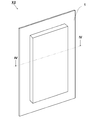
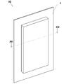
- FIG. 1 shows a perspective view of an electrochemical cell X1.
- FIG. 2 shows a cross-sectional view of the electrochemical cell X1 of FIG. 1 taken along the line II-II.
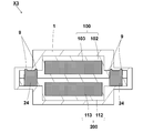
- the perspective view of the electrochemical cell X2 is shown.
- FIG. 4 shows a cross-sectional view of the electrochemical cell X2 of FIG. 3 taken along the line IV-IV.
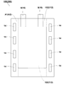
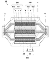
- a top view of a stack of the first unit cell and the second unit cell taken out from the outer container of the electrochemical cell X2 and viewed from the stacking direction of the first unit cell and the second unit cell is shown.
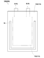
- the perspective view of the electrochemical cell X3 is shown.
- FIG. 7 shows a cross-sectional view of the electrochemical cell X3 of FIG. 6 taken along the line VII-VII.
- FIG. 10 is a cross-sectional view of the electrochemical cell X4 of FIG. 9 taken along line XX.
- a top view of a stack of the first unit cell and the second unit cell taken out of the outer container of the electrochemical cell X4 and viewed from the stacking direction of the first unit cell and the second unit cell is shown.
- the perspective view of the electrochemical cell X5 is shown.
- FIG. 13 shows a cross-sectional view of the electrochemical cell X5 of FIG. 12 taken along the line XIII-XIII.
- the electrochemical cell X1 will be described in detail with reference to FIGS. As shown in FIGS. 1 and 2, the electrochemical cell X ⁇ b> 1 includes a first single cell 100, a second single cell 200, an outer container 1 for storing the first single cell 100 and the second single cell 200, It has. Further, the first unit cell 100 and the second unit cell 200 are fixed by the welded part 4.
- the first single cell 100 is the smallest unit member that functions as a battery in the electrochemical cell X1.
- the first unit cell 100 is, for example, a lithium ion battery.
- the first single cell 100 includes a first power generation element 3, a first inner container 2, and a first terminal 8.
- the first single cell 100 has, for example, a plate shape.
- the first single cell 100 can flow electricity to the external device by being electrically connected to the external device.
- the first power generating element 3 is a member for storing and discharging electricity using an electrochemical reaction.
- the first power generating element 3 includes, for example, a positive electrode 5, a negative electrode 6, and a separator 7 between the positive electrode 5 and the negative electrode 6.
- the first power generating element 3 can exchange cations and anions between the positive electrode 5 and the negative electrode 6 through the separator 7.
- the first power generation element 3 can flow electricity to the external device by electrically connecting the positive electrode 5 and the negative electrode 6 to the external device.
- the first power generating element 3 is, for example, a laminate of the positive electrode 5, the separator 7, and the negative electrode 6.
- the first power generation element 3 is, for example, plate-shaped.
- a positive electrode 5, a separator 7, and a negative electrode 6 are stacked in a plate-shaped thickness direction.
- the positive electrode 5 and the negative electrode 6 are, for example, electrochemically active substances.
- the positive electrode 5 and the negative electrode 6 may have, for example, an active material and an electrolyte.
- As the electrolyte for example, a solution obtained by adding a salt to a solvent or a solvent mixture can be used.
- the separator 7 is a member provided for exchanging cations and anions between the positive electrode 5 and the negative electrode 6.
- the separator 7 may have, for example, fine holes through which cations and anions pass.
- a porous insulating material can be used for the separator 7, for example, Specifically, for example, polyolefin or polyvinyl chloride can be used as the separator 7.
- the first power generation element 3 can electrically insulate the positive electrode 5 and the negative electrode 6.
- the first power generating element 3 When the first power generating element 3 is plate-shaped, it can be set to, for example, 50 to 500 mm in length, 50 to 300 mm in width, and 0.1 to 2 mm in thickness.
- the first inner container 2 is a member having a space for wrapping the first power generation element 3 inside the first inner container 2.
- the first inner container 2 is provided to protect the first power generation element 3 from an external environment. More specifically, the first inner container 2 is provided to protect the first power generation element 3 from oxygen and water in the air.
- the first inner container 2 is provided so as to cover the entire first power generation element 3.
- the first inner container 2 has, for example, a bag shape.
- the first inner container 2 is formed, for example, by forming one member into a bag shape.
- the first inner container 2 may be formed by welding two members, for example.
- the first inner container 2 may have a rectangular shape when viewed from the lamination direction of the positive electrode 5, the separator 7, and the negative electrode 6.
- the first inner container 2 has, for example, an insulating material. This makes it difficult for the external environment and the first power generation element 3 to be short-circuited via the first inner container 2. Therefore, the first inner container 2 can protect the first power generation element 3 from the external environment.
- the first inner container 2 has, for example, a resin material. More specifically, for example, polyethylene terephthalate or polyethylene can be used as the resin material.
- the first inner container 2 may have, for example, a multilayer structure.
- the first inner container 2 may have, for example, a two-layer structure.
- the first inner container 2 has, for example, a heat-adhesive resin material and a heat-resistant resin material.
- the heat-adhesive resin material is a resin whose melting temperature is lower than 100 ° C.
- the heat-resistant resin material is, specifically, a resin having a melting temperature of 100 ° C. or more and 300 ° C. or less.
- the heat-resistant resin material for example, polyethylene terephthalate or polyethylene naphthalate can be used.
- the heat-adhesive resin material for example, polyethylene or polypropylene can be used.
- the length is 55 to 550 mm
- the width is 55 to 350 mm
- the thickness is 0.1. It can be set to ⁇ 2.2mm.
- the first terminal 8 is provided for electrically connecting the first power generating element 103 to an external device.
- the first terminal 8 has, for example, a plate shape. Specifically, when viewed from the stacking direction of the first unit cell 100 and the second unit cell 200, the first terminal 8 has, for example, a rectangular shape.
- the first terminal 8 may be, for example, rectangular.
- the rectangular shape may have, for example, a long side and a short side.
- the first terminal 8 is in contact with the first power generation element 103 when viewed from the stacking direction of the first unit cell 100 and the second unit cell 200. When viewed from the stacking direction of the first unit cell 100 and the second unit cell 200, the first terminal 8 is located on any side of the outer periphery of the first power generation element 103.
- the first terminal 8 extends outside the first inner container 102 in order to be electrically connected to an external device.
- the first terminal 8 is electrically connected to an external connection terminal outside the first inner container 102.
- the first terminal 8 is, for example, a conductive member.
- the first terminal 8 may include, for example, a metal material. More specifically, for example, aluminum or copper can be used as the metal material.
- the first terminal 8 When the first terminal 8 has a plate shape, it can be set to, for example, 30 to 100 mm in length, 10 to 100 mm in width, and 0.1 to 0.5 mm in thickness.
- the second unit cell 200 is provided for supplying electricity to an external device, like the first unit cell 100.
- the first unit cell 100 and the second unit cell 200 are connected in parallel. Thereby, the capacity of the electrochemical cell X1 can be increased. Further, the first unit cell 100 and the second unit cell 200 may be connected in series. Thereby, the voltage of the electrochemical cell X1 can be increased.
- the second unit cell 200 is stacked on the first unit cell 100 in the outer container 1.
- the second single cell 200 includes the second power generation element 13 and the second inner container 12.
- the second unit cell 200 has the same shape as the first unit cell 100 in the electrochemical cell X1. However, the second unit cell 200 may have a different shape from the first unit cell 100, for example.
- the second unit cell 200 is stacked with the first unit cell 100 so as to have the same outer periphery. However, the second unit cell 200 may be stacked without aligning the outer periphery with the first unit cell 100.
- the material used for the first power generation element 3 can be used. More specifically, the second power generation element 13 may be formed of, for example, the same material as the first power generation element 3. Further, as the second power generation element 13, for example, a material different from that of the first power generation element 3 may be used.
- the second inner container 12 has the same shape as the first inner container 2 in the electrochemical cell X1. However, the second inner container 12 may have a shape different from that of the first inner container 2, for example. As the second inner container 12, for example, the material used for the first inner container 2 can be used. More specifically, the second inner container 12 may use the same material as the first inner container 2. Further, as the second inner container 12, for example, a material different from that of the first inner container 2 may be used.
- the second unit cell 200 can be set to the same size as the first unit cell 100, for example.
- the second unit cell 200 may have a different size from the first unit cell 100, for example.
- the outer container 1 is a member having a space for wrapping the first unit cell 100 and the second unit cell 200 inside the outer container 1.
- the outer container 1 is a member for protecting the first unit cell 100 and the second unit cell 200 from an external environment. More specifically, the outer container 1 is a member for protecting the first unit cell 100 and the second unit cell 200 from oxygen and moisture in the air.
- the outer container 1 has, for example, a bag shape.
- the outer container 1 is formed, for example, by forming one member into a bag shape.
- the outer container 1 may be formed by welding two members, for example.
- the outer container 1 may have a rectangular shape when viewed from the direction in which the first unit cells 100 and the second unit cells 200 are stacked.
- the outer container 1 has, for example, an insulating material. This makes it difficult for the external environment and the first unit cell 100 and the second unit cell 200 to be short-circuited via the outer container 1. Therefore, the outer container 1 can protect the first single cell 100 and the second single cell 200 from the external environment.
- a resin material can be used. More specifically, as the resin material, for example, polyethylene terephthalate or polyethylene can be used.
- the outer container 1 has, for example, a multilayer structure.
- the outer container 1 may have, for example, a three-layer structure.
- the outer container 1 may have, for example, a first insulating layer, a moisture-proof layer, and a second insulating layer.
- the moisture-proof layer is located, for example, between the first insulating layer and the second insulating layer.
- the moisture-proof layer may be covered with, for example, a first insulating layer and a second insulating layer.
- the first insulating layer has, for example, a resin material.
- a resin material for example, polyethylene terephthalate or polyethylene naphthalate can be used as the resin material.
- the moisture-proof layer is provided to make it difficult for oxygen and water that have permeated the first resin layer to reach the second resin layer.
- the moisture-proof layer has, for example, a metal material. Specifically, as the metal material, for example, aluminum or copper can be used.
- the second resin layer has, for example, a resin material.
- a resin material for example, polyethylene or polypropylene can be used.
- the outer container 1 has the moisture-proof layer, the first unit cell 100 and the second unit cell 200 can be protected from oxygen and water that have permeated the first resin layer. As a result, the possibility that the first unit cell 100 and the second unit cell 200 are damaged can be reduced.
- the outer container 1 When the outer container 1 is rectangular when viewed from the lamination direction of the first unit cell 100 and the second unit cell 200, the outer container 1 can be set to, for example, 60 to 600 mm in length, 60 to 400 mm in width, and 1 to 20 mm in thickness. .
- Welding part 4 is a portion where first inner container 2 and second inner container 12 are welded.
- the welding part 4 is provided for fixing the first unit cell 100 and the second unit cell 200.
- the material of the first inner container 2 and the material of the second inner container 12 may be mutually diffused.
- the material of the first inner container 2 and the material of the second inner container 12 may be entangled in the welded portion 4.
- the welded portion 4 may have, for example, a crystalline portion in which molecules of the material of the first inner container 2 and molecules of the material of the second inner container 12 are arranged in a certain rule.
- the first inner container 2 and the second inner container 12 are welded, so that the first single cell 100 and the second single cell 200 are fixed in the outer container 1. Therefore, the possibility that the positions of the first unit cell 100 and the second unit cell 200 are shifted can be reduced without increasing the size of the electrochemical cell X1. As a result, it is possible to reduce the possibility that the reliability of the electrical connection of the electrochemical cell X1 is impaired, while reducing the possibility that the thickness is partially increased at the fixed portion.
- the welded portion 4 is located, for example, between the first power generation element 3 and the second power generation element 13.
- the welding portion 4 has, for example, a plate shape.
- the welded portion 4 has, for example, a band shape when viewed from the stacking direction of the first unit cell 100 and the second unit cell 200.
- the welding portion 4 may be, for example, a square shape.
- the corner of the square shape may be rounded. This makes it difficult for external force to concentrate on the corners of the quadrangular welded portion 4, thereby reducing the possibility of the welded portion 4 being damaged.
- the welding portion 4 has, for example, an insulating material.
- a resin material can be used.
- polyethylene terephthalate or polyethylene may be used as the welding portion 4.
- the welding portion 4 for example, a material whose light transmittance changes when welded can be used. Thereby, the welded portion 4 can be easily visually confirmed. Further, as the welded portion 4, for example, a material whose hardness increases when welded may be used. Thereby, the possibility that the electrochemical cell X1 is deformed by receiving an external force can be reduced. As a result, the reliability of the electrical connection of the electrochemical cell X1 can be improved.
- the welded portion 4 When the welded portion 4 is plate-shaped, it can be set to, for example, 1 to 100 mm in length, 1 to 20 mm in width, and 0.02 to 1 mm in thickness.
- Welding part 4 is formed by, for example, ultrasonic welding of first inner container 2 and second inner container 12.
- the horn referred to here is a member that vibrates at a frequency of, for example, 20 to 40 kHz.
- the horn has a head portion that contacts a position to be welded, and a connection portion that transmits vibration to the head portion.
- the head portion has a rectangular shape when viewed from the laminating direction of the first inner container 2 and the second inner container 12, for example. Further, the head portion may have, for example, a square shape.
- the horn is vibrated to apply vibration energy to the first inner container 2 and the second inner container 12.
- the interface where the first inner container 2 and the second inner container 12 come into contact with each other is melted by the vibration energy transmitted from the horn.
- the welded portion 4 is formed by cooling the portion where the first inner container 2 and the second inner container 12 are melted while applying pressure.
- the welded portion 4 may be formed by, for example, heat sealing the first inner container 2 and the second inner container 12.
- heat sealing method will be described more specifically.
- the heated metal plate is brought into contact with a position where the first inner container 2 and the second inner container 12 are welded.
- heat is applied to the first inner container 2 and the second inner container 12 to melt them.
- the welded part 4 is formed by cooling the portion where the first inner container 2 and the second inner container 12 are melted.
- the metal plate is heated to, for example, 100 to 200 ° C.
- the metal plate has, for example, a plate shape. Specifically, the metal plate has a rectangular shape when viewed from the laminating direction of the first inner container 2 and the second inner container 12.
- the metal plate may be, for example, square.
- the weld 4 is not limited to the method of ultrasonic welding and heat sealing, and may be formed by any method.
- the electrochemical cell X2 will be described in detail with reference to FIGS. As shown in FIGS. 3 and 4, the electrochemical cell X2 includes a first unit cell 100, a second unit cell 200, an outer container 1 containing the first unit cell 100 and the second unit cell 200, It has. Further, the first unit cell 100 and the second unit cell 200 are fixed by the welded part 14.
- the electrochemical cell X2 is different from the electrochemical cell X1 in the shape of the first power generation element 103, the shape of the first inner container 102, the shape of the second power generation element 113, and the shape of the second inner container 112. Furthermore, the position and the shape of the welding portion 14 of the electrochemical cell X2 are different from those of the electrochemical cell X1. The other parts are the same as those of the electrochemical cell X1, and a description thereof will be omitted.
- the first unit cell 100 has a first power generation element 103 and a first inner container 102.
- the first power generation element 103 has, for example, a rectangular shape when viewed from the stacking direction of the first unit cell 100 and the second unit cell 200. More specifically, the first power generating element 103 may have, for example, a rectangular shape having a long side and a short side.
- the first inner container 102 has, for example, a rectangular shape when viewed from the stacking direction of the first unit cell 100 and the second unit cell 200. More specifically, the first inner container 102 may be, for example, a rectangular shape having a long side and a short side. Further, the first inner container 102 has a first peripheral portion A1.
- the first peripheral portion A1 is a portion located around the first inner container 102. Specifically, the first peripheral portion A1 extends from the outer periphery of the first inner container 102 to the outer periphery of the first power generation element 103 when viewed from the stacking direction of the first unit cell 100 and the second unit cell 200. Means area. That is, the first peripheral portion A1 is a region where the first power generation element 103 and the first inner container 102 do not overlap.
- the second unit cell 200 has the second power generation element 113 and the second inner container 112.
- the second power generation element 113 has the same shape as the first power generation element 103 in the electrochemical cell X2.
- the first power generation element 103 and the second power generation element 113 may have different shapes.
- the material used for the first power generation element 103 can be used for the second power generation element 113. More specifically, the second power generation element 113 may be formed of, for example, the same material as the first power generation element 103.
- the second inner container 112 has the same shape as the first inner container 102 in the electrochemical cell X2. However, the second inner container 112 and the first inner container 102 may have different shapes, for example.
- the material used for the first inner container 102 can be used for the second inner container 112.
- the second inner container 112 may be formed of, for example, the same material as the first inner container 102.
- the second inner container 112 has a second peripheral portion A2.
- the second peripheral portion A2 is a portion around the second inner container 112. Specifically, the second peripheral portion A2 extends from the outer periphery of the second inner container 112 to the outer periphery of the second power generation element 113 when viewed from the stacking direction of the first unit cell 100 and the second unit cell 200. Means area. That is, this is an area where the second power generation element 113 and the second inner container 112 do not overlap.
- the first power generation element 103 and the second power generation element 113 are stacked such that their long sides and their short sides are aligned when viewed from the stacking direction of the first unit cell 100 and the second unit cell 200. I have.
- the first inner container 102 and the second inner container 112 are stacked such that their long sides and their short sides are aligned when viewed from the stacking direction of the first unit cell 100 and the second unit cell 200. Have been.
- the positive electrode 5, the separator 7, and the negative electrode 6 of the first power generation element 103 and the second power generation element 113 are omitted.
- the welding portion 14 has a first peripheral portion A1 and a second peripheral portion A2 welded.
- the welded portion 14 and the first An interval can be provided between the power generating element 103 and the second power generating element 113. Therefore, the effect of thermal stress due to the heat generated from the first power generation element 103 and the second power generation element 113 in the welded portion 14 can be reduced. As a result, the possibility that the welded portion 14 is damaged can be reduced.
- a stack of the first unit cell 100 and the second unit cell 200 is taken out of the outer container 1 of the electrochemical cell X2, and is taken out from the stacking direction of the first unit cell 100 and the second unit cell 200. It shows a top view when viewed. Peripheries of the first power generation element 103 and the second power generation element 113 when viewed from the lamination direction of the first power generation element 103 and the second power generation element 113 through the first inner container 102 and the second inner container 112 Is indicated by a dotted line. Further, the extension lines of the long sides of the first power generation element 103 and the second power generation element 113 are indicated by dashed lines as virtual lines.
- a plurality of welding portions 14 may be provided.
- the plurality of welds 14 can distribute external force to the plurality of welds 14. Therefore, it is possible to make it difficult for the external force to concentrate on one welded portion 14. As a result, the possibility that the welded portion 14 is damaged can be reduced.
- the welding portion 14 may be located along each long side of the first power generation element 103 and the second power generation element 113. Further, the welded portion 14 may be located along an extension of a long side of each of the first power generation element 103 and the second power generation element 113. Thereby, the possibility that the first unit cell 100 or the second unit cell 200 is displaced in the short side direction can be reduced by arranging the welded portion along the long side that is easily subjected to external force. As a result, the reliability of the electrical connection of the electrochemical cell can be improved.
- the welded portion 14 when viewed from the laminating direction of the first unit cell 100 and the second unit cell 200, the welded portion 14 has, for example, a rectangular shape. Specifically, the welding portion 14 may be, for example, a rectangle having long sides. At this time, the long side of the welded portion 14 may be along each long side of the first power generation element 103. Thereby, the welded portion can be located along the long side that is likely to receive an external force. Therefore, the possibility that the first unit cell 100 or the second unit cell 200 is displaced in the short side direction can be reduced. As a result, the reliability of the electrical connection of the electrochemical cell can be improved.
- the electrochemical cell X3 will be described in detail with reference to FIGS. As shown in FIGS. 6 and 7, the electrochemical cell X3 includes a first single cell 100, a second single cell 200, an outer container 1 for storing the first single cell 100 and the second single cell 200, It has. Further, the first unit cell 100 and the second unit cell 200 are fixed by the welding part 24. The electrochemical cell X3 is different from the electrochemical cell X2 in that the position of the welding portion 24 is different and that the welding portion 24 has the convex portion 9. The other parts are the same as those of the electrochemical cell X2, and the description is omitted.
- FIG. 8 similarly to FIG. 5, the first cell 100 and the second cell 200 from the outer container 1 of the electrochemical cell X3 are stacked with their long sides and their short sides aligned.
- FIG. 3 shows a top view of the first unit cell 100 and the second unit cell 200 when viewed from the stacking direction. Further, the extension lines of the long sides and the short sides of the first power generation element 103 and the second power generation element 113 are indicated by dashed lines as virtual lines.
- the welded portions 24 are located at the four corners of the first peripheral portion A1 and the second peripheral portion A2.
- the four corners of the first peripheral part A1 and the second peripheral part A2 are formed by extending the long side of each of the first power generation element 103 and the second power generation element 113 and the first power generation element 103 and the second power generation element. It means a region surrounded by an extension of each short side of the element 113 and the outer periphery of the first inner container 102 and the second inner container 112.
- the first unit cell 100 and the second unit cell 200 can be made hard to deform.
- the reliability of the electrical connection of the electrochemical cell can be improved.
- the welded portion 24 has the convex portion 9.
- the protrusion 9 is provided to disperse an external force applied to the welding portion 24 to the protrusion 9 itself. Thereby, the possibility that the welded portion 24 is damaged can be reduced.
- the protrusion 9 is provided, for example, at a position adjacent to the welding portion 24. Specifically, the protrusion 9 may be located, for example, along the outer periphery of the welded portion 24.
- the projections 9 are linear. More specifically, when viewed from the stacking direction of the first unit cell 100 and the second unit cell 200, the protrusion 9 has a frame shape. Further, as shown in FIG. 7, the cross section of the convex portion 9 has a semicircular shape.
- the protrusion 9 has, for example, an insulating material.
- a resin material may be used. More specifically, as the resin material, for example, polyethylene terephthalate or polyethylene may be used.
- the projection 9 can be formed of the same material as that of the welding part 24. Therefore, the thermal expansion coefficients of the convex portion 9 and the welded portion 24 can be made equal. As a result, it is possible to reduce the possibility that the projection 9 and the welded portion 24 are separated due to the difference in the coefficient of thermal expansion.
- the projection 9 may be formed at the same time, for example, when the welded portion 24 is formed.
- the protrusion 9 may be formed of, for example, a material different from the material of the weld 24. More specifically, the protrusion 9 may have a higher elastic modulus than the weld 24. Thereby, when an external force is applied to the convex portion 9, the convex portion 9 is deformed, so that the external force is not easily transmitted to the welded portion 24. Therefore, the possibility that the welded portion 24 is damaged can be reduced.
- a plurality of convex portions 9 may be provided for one welded portion 24, for example. This makes it possible to disperse the external force to the plurality of convex portions 9, so that it is difficult for the external force to concentrate on one convex portion 9. Therefore, the possibility that the protrusion 9 is damaged can be reduced.
- the length is 1 to 50 mm
- the width is 1 to 10 mm
- the thickness is 0.1 to 5 mm. Can be set.
- the electrochemical cell X4 will be described in detail with reference to FIGS.
- the electrochemical cell X4 is different from the electrochemical cell X3 in that the first unit cell 100 has the first terminal 8 and the second unit cell 200 has the second terminal 18. Further, the electrochemical cell X4 is different from the electrochemical cell X3 in that the position of the welding portion 34 is different.
- the other parts are the same as those of the electrochemical cell X3, and the description is omitted.
- FIG. 11 shows a top view of the first unit cell 100 and the second unit cell 200 when viewed from the stacking direction.
- the first power generating element 103 has the first terminal 8 extending from any side to the outside.
- the first terminal 8 is provided for electrically connecting the first power generation element 103 to an external device.
- the first terminal 8 has, for example, a plate shape.
- the first terminal 8 has, for example, a rectangular shape when viewed from the stacking direction of the first unit cell 100 and the second unit cell 200.
- the first terminal 8 may be, for example, rectangular.
- the rectangular shape may have, for example, a long side and a short side.
- the first terminal 8 is in contact with the first power generation element 103 when viewed from the stacking direction of the first unit cell 100 and the second unit cell 200.
- the first terminal 8 is located on any side of the outer periphery of the first power generation element 103.
- the first terminal 8 extends outside the first inner container 102 so as to be electrically connected to an external device.
- the first terminal 8 is, for example, a conductive member.
- the first terminal 8 may include, for example, a metal material. More specifically, for example, aluminum or copper can be used as the metal material.
- the first terminal 8 When the first terminal 8 has a plate shape, it can be set to, for example, 30 to 100 mm in length, 10 to 100 mm in width, and 0.1 to 0.5 mm in thickness.
- the second power generation element 113 has the second terminal 18 extending from any side to the outside.
- the second terminal 18 has the same shape as the first terminal 8.
- the second terminal 18 may have a different shape from the first terminal 8, for example.
- the material used for the first terminal 8 can be used for the second terminal 18.
- the second terminal 18 may be formed of, for example, the same material as the first terminal 8.
- the second terminal 18 when viewed from the stacking direction of the first unit cell 100 and the second unit cell 200, the second terminal 18 is located on any side of the outer periphery of the first power generation element 103. . Further, the second terminal 18 extends outside the second inner container 112 to be electrically connected to an external device. Further, in the electrochemical cell X4, the second terminal 18 overlaps the first terminal 8 with its outer periphery aligned when viewed from the stacking direction of the first unit cell 100 and the second unit cell 200. In FIG. 11, when viewed from the stacking direction of the first unit cell 100 and the second unit cell 200, the first terminal 8 and the second terminal 18, the first inner container 102, and the second inner container 112 The overlapping portion is indicated by a dotted line.
- the first power generation element 103 and the second power generation element 113 each have terminals extending from any side to the outside.
- the welding part 34 may be located along the side where each terminal is not located. This makes it possible to reduce the influence of an external force applied to the electrochemical cell X4 at a position distant from each terminal fixed to the external device when the vibration is transmitted from the outside to the electrochemical cell X4.
- the welded portion 34 is located at the first terminal 8 and the second terminal 18. It is located along the outer peripheral sides of the first power generation element 103 and the second power generation element 113 that are not provided. More specifically, the side of the outer periphery of the first power generation element 103 and the second power generation element 113 where the first terminal 8 and the second terminal 18 are not located is defined as the first power generation element 103 and the second power generation element 113. This means a side where the outer side does not overlap the first terminal 8 and the second terminal 18.
- the first unit cell 100 is located at a position away from the first terminal 8 and the second terminal 18.
- the second unit cell 200 can be fixed. Therefore, the influence of the external force applied to the first unit cell 100 and the second unit cell 200 can be reduced. As a result, the reliability of the electrical connection of the electrochemical cell X4 can be improved.
- the first inner container 102 and the second inner container 112 are welded to the welding portion 34 via the separator 7.
- the separator 7, which is a part of the first power generation element 103, and the first inner container 102 are fixed by the welding portion 34.
- the separator 7, which is a part of the second power generation element 113, and the second inner container 112 are fixed by the welding portion 34. Therefore, the possibility that the positions of the first power generation element 103 and the first inner container 102 are shifted can be reduced. Further, it is possible to reduce the possibility that the positions of the second power generation element 113 and the second inner container 112 are shifted. As a result, the reliability of the electrical connection between the first unit cell 100 and the second unit cell 200 can be improved.
- the number of single cells included in the electrochemical cell is not limited to two.
- the electrochemical cell may have three or more single cells. In this case, the welded portion only needs to fix at least two of the three or more unit cells.
- the electrochemical cell X5 has three single cells. The electrochemical cell X5 will be described in detail with reference to FIGS. In the electrochemical cell X5, the welding unit 44 fixes three single cells together.
- the electrochemical cell X5 includes a first unit cell 100, a second unit cell 200, a third unit cell 300, a first unit cell 100, a second unit cell 200, and a second unit cell 200. And an outer container 1 for storing the three single cells 300. Further, the first unit cell 100, the second unit cell 200, and the third unit cell 300 are fixed by the welding unit 44.
- the electrochemical cell X5 is different from the electrochemical cell X4 in that it has the third single cell 300.
- the electrochemical cell X5 is otherwise the same as the electrochemical cell X4, and is therefore omitted.
- the third single cell 300 has the third power generation element 23 and the third inner container 22.
- the third power generation element 23 has the same shape as the first power generation element 103 and the second power generation element 113 in the electrochemical cell X5.
- the third power generation element 23 may have a different shape from the first power generation element 103 and the second power generation element 113.
- a material used for the first power generation element 103 and the second power generation element 113 can be used for the third power generation element 23 may be formed of the same material as the first power generation element 103 and the second power generation element 113, for example.
- the first power generation element 103, the second power generation element 113, and the third power generation element 23 When viewed from the stacking direction of the first power generation element 103, the second power generation element 113, and the third power generation element 23, the first power generation element 103, the second power generation element 113, and the third power generation element 23 have long sides. It has a rectangular shape with short sides. The first power generation element 103, the second power generation element 113, and the third power generation element 23 are stacked with their long sides and their short sides aligned.
- the third inner container 22 has the same shape as the first inner container 102 and the second inner container 112 in the electrochemical cell X5. However, the third inner container 22 may have a different shape from the first inner container 102 and the second inner container 112, for example.
- the third inner container 22 can be made of a material used for the first inner container 102 and the second inner container 112. Specifically, the third inner container 22 may be formed of the same material as the first inner container 102 and the second inner container 112, for example.
- the electrochemical cell X5 has a welded portion 44 in which the first unit cell 100, the second unit cell 200, and the third unit cell 300 are welded.
- the welding portion 44 is provided for fixing the first unit cell 100, the second unit cell 200, and the third unit cell 300. More specifically, as shown in FIG. 13, the welding unit 44 fixes the first unit cell 100, the second unit cell 200, and the third unit cell 300 together. Thereby, the first unit cell 100, the second unit cell 200, and the third unit cell 300 can be fixed more firmly than when at least two unit cells are fixed. Therefore, the reliability of the electrical connection of the electrochemical cell X5 can be improved.
- each single cell, each power generation element, each inner container, and each terminal are shown in the same shape and the outer periphery is aligned, but in a strict sense. It is not necessary for the outer periphery to be uniform in the same shape. For example, if the first power generation element 103 and the second power generation element 113 have an error of 5 mm or less, they can be regarded as having the same shape and overlapping with their outer circumferences aligned. This is the same for each single cell, each inner container, and each terminal.
- Electrochemical cell 1 Outer container 2, 102 First inner container 3, 103 First power generating element 4, 14, 24, 34, 44 Welding part 5 Positive electrode 6 Negative electrode 7 Separator 8 First terminal 9 Convex part 12, 112 2nd inner container 13, 113 2nd power generation element 18 2nd terminal 22 3rd inner container 23 3rd power generation element 28 3rd terminal 100 1st single cell 200 2nd single cell 300 3rd single cell A1 1st peripheral part A2 2nd rim
Landscapes
- Chemical & Material Sciences (AREA)
- Chemical Kinetics & Catalysis (AREA)
- Electrochemistry (AREA)
- General Chemical & Material Sciences (AREA)
- Engineering & Computer Science (AREA)
- Manufacturing & Machinery (AREA)
- Connection Of Batteries Or Terminals (AREA)
- Sealing Battery Cases Or Jackets (AREA)
- Secondary Cells (AREA)
- Battery Mounting, Suspending (AREA)
- Laminated Bodies (AREA)
- Compositions Of Macromolecular Compounds (AREA)
- Manufacturing Of Printed Wiring (AREA)
Abstract
L'invention concerne une cellule électrochimique comprenant : une première cellule unitaire ayant un premier élément de production d'énergie et un premier récipient qui loge le premier élément de production d'énergie ; une seconde cellule unitaire ayant un second élément de production d'énergie et un second récipient qui loge le second élément de production d'énergie ; et un récipient externe qui loge la première cellule unitaire et la seconde cellule unitaire. La cellule électrochimique a une section fusionnée dans laquelle la première cellule unitaire et la seconde cellule unitaire sont empilées et le premier récipient et le second récipient sont fusionnés.
Priority Applications (7)
| Application Number | Priority Date | Filing Date | Title |
|---|---|---|---|
| CN202411156632.7A CN119050606A (zh) | 2018-06-27 | 2019-06-26 | 电化学电池 |
| EP19825860.0A EP3817084A4 (fr) | 2018-06-27 | 2019-06-26 | Cellule électrochimique |
| US17/252,730 US11764443B2 (en) | 2018-06-27 | 2019-06-26 | Electrochemical cell |
| CN201980030018.7A CN112074967A (zh) | 2018-06-27 | 2019-06-26 | 电化学电池 |
| JP2020527573A JP7119088B2 (ja) | 2018-06-27 | 2019-06-26 | 電気化学セル |
| JP2022124369A JP7480230B2 (ja) | 2018-06-27 | 2022-08-03 | 電気化学セル |
| JP2024070980A JP2024099715A (ja) | 2018-06-27 | 2024-04-24 | 電気化学セル |
Applications Claiming Priority (2)
| Application Number | Priority Date | Filing Date | Title |
|---|---|---|---|
| JP2018-121980 | 2018-06-27 | ||
| JP2018121980 | 2018-06-27 |
Publications (1)
| Publication Number | Publication Date |
|---|---|
| WO2020004458A1 true WO2020004458A1 (fr) | 2020-01-02 |
Family
ID=68986543
Family Applications (1)
| Application Number | Title | Priority Date | Filing Date |
|---|---|---|---|
| PCT/JP2019/025368 Ceased WO2020004458A1 (fr) | 2018-06-27 | 2019-06-26 | Cellule électrochimique |
Country Status (5)
| Country | Link |
|---|---|
| US (1) | US11764443B2 (fr) |
| EP (1) | EP3817084A4 (fr) |
| JP (3) | JP7119088B2 (fr) |
| CN (2) | CN112074967A (fr) |
| WO (1) | WO2020004458A1 (fr) |
Cited By (1)
| Publication number | Priority date | Publication date | Assignee | Title |
|---|---|---|---|---|
| JPWO2022215342A1 (fr) * | 2021-04-09 | 2022-10-13 |
Citations (5)
| Publication number | Priority date | Publication date | Assignee | Title |
|---|---|---|---|---|
| JP2004055153A (ja) * | 2002-07-16 | 2004-02-19 | Nissan Motor Co Ltd | 積層型電池 |
| JP2004071302A (ja) * | 2002-08-05 | 2004-03-04 | Toyota Motor Corp | 蓄電素子モジュール及びその製造方法 |
| JP2013048042A (ja) | 2011-08-29 | 2013-03-07 | Panasonic Corp | 電池包装体 |
| JP2015179618A (ja) * | 2014-03-19 | 2015-10-08 | 凸版印刷株式会社 | 外装ケース、外装ケース用ラミネートフィルム、及び、電池モジュール |
| JP2017130378A (ja) * | 2016-01-21 | 2017-07-27 | トヨタ自動車株式会社 | ラミネート電池モジュール |
Family Cites Families (14)
| Publication number | Priority date | Publication date | Assignee | Title |
|---|---|---|---|---|
| JPH04104455A (ja) * | 1990-08-22 | 1992-04-06 | Shin Kobe Electric Mach Co Ltd | 密閉形鉛蓄電池 |
| JP3964521B2 (ja) | 1997-12-02 | 2007-08-22 | 株式会社東芝 | 組電池 |
| JP2002100341A (ja) * | 2000-09-21 | 2002-04-05 | Denso Corp | 電 池 |
| JP4203261B2 (ja) * | 2002-05-21 | 2008-12-24 | 日産自動車株式会社 | 二次電池モジュール |
| WO2004059760A1 (fr) * | 2002-12-25 | 2004-07-15 | Fuji Jukogyo Kabushiki Kaisha | Batterie d'accumulateurs |
| JP2006172994A (ja) | 2004-12-17 | 2006-06-29 | Nissan Motor Co Ltd | 組電池および組電池の製造方法 |
| KR100870355B1 (ko) * | 2007-07-19 | 2008-11-25 | 삼성에스디아이 주식회사 | 파우치형 전지팩 |
| DE102009031014A1 (de) * | 2009-06-29 | 2010-12-30 | Li-Tec Battery Gmbh | Verfahren zum Herstellen einer Batterieanordnung |
| KR101259442B1 (ko) * | 2011-07-01 | 2013-05-31 | 지에스나노텍 주식회사 | 박막 전지 패키징 방법 및 박막 전지 패키지 제조 장치 |
| WO2013042612A1 (fr) * | 2011-09-21 | 2013-03-28 | Necエナジーデバイス株式会社 | Accumulateur à gaine de film et accumulateur assemblé |
| JP2014078498A (ja) * | 2012-09-19 | 2014-05-01 | Toshiba Corp | 電池モジュール |
| JP2018113097A (ja) * | 2015-05-21 | 2018-07-19 | パナソニックIpマネジメント株式会社 | 組電池 |
| KR102606052B1 (ko) * | 2015-06-18 | 2023-11-27 | 24엠 테크놀로지즈, 인크. | 단일 파우치 배터리 셀들 및 제조 방법들 |
| JP6743664B2 (ja) | 2016-11-18 | 2020-08-19 | 株式会社Gsユアサ | 蓄電装置及び蓄電装置の製造方法 |
-
2019
- 2019-06-26 WO PCT/JP2019/025368 patent/WO2020004458A1/fr not_active Ceased
- 2019-06-26 CN CN201980030018.7A patent/CN112074967A/zh active Pending
- 2019-06-26 JP JP2020527573A patent/JP7119088B2/ja active Active
- 2019-06-26 EP EP19825860.0A patent/EP3817084A4/fr active Pending
- 2019-06-26 CN CN202411156632.7A patent/CN119050606A/zh active Pending
- 2019-06-26 US US17/252,730 patent/US11764443B2/en active Active
-
2022
- 2022-08-03 JP JP2022124369A patent/JP7480230B2/ja active Active
-
2024
- 2024-04-24 JP JP2024070980A patent/JP2024099715A/ja active Pending
Patent Citations (5)
| Publication number | Priority date | Publication date | Assignee | Title |
|---|---|---|---|---|
| JP2004055153A (ja) * | 2002-07-16 | 2004-02-19 | Nissan Motor Co Ltd | 積層型電池 |
| JP2004071302A (ja) * | 2002-08-05 | 2004-03-04 | Toyota Motor Corp | 蓄電素子モジュール及びその製造方法 |
| JP2013048042A (ja) | 2011-08-29 | 2013-03-07 | Panasonic Corp | 電池包装体 |
| JP2015179618A (ja) * | 2014-03-19 | 2015-10-08 | 凸版印刷株式会社 | 外装ケース、外装ケース用ラミネートフィルム、及び、電池モジュール |
| JP2017130378A (ja) * | 2016-01-21 | 2017-07-27 | トヨタ自動車株式会社 | ラミネート電池モジュール |
Cited By (1)
| Publication number | Priority date | Publication date | Assignee | Title |
|---|---|---|---|---|
| JPWO2022215342A1 (fr) * | 2021-04-09 | 2022-10-13 |
Also Published As
| Publication number | Publication date |
|---|---|
| JP2024099715A (ja) | 2024-07-25 |
| CN112074967A (zh) | 2020-12-11 |
| JP7480230B2 (ja) | 2024-05-09 |
| EP3817084A1 (fr) | 2021-05-05 |
| EP3817084A4 (fr) | 2022-03-09 |
| JP7119088B2 (ja) | 2022-08-16 |
| US20210218115A1 (en) | 2021-07-15 |
| JP2022160565A (ja) | 2022-10-19 |
| CN119050606A (zh) | 2024-11-29 |
| JPWO2020004458A1 (ja) | 2021-06-24 |
| US11764443B2 (en) | 2023-09-19 |
Similar Documents
| Publication | Publication Date | Title |
|---|---|---|
| JP7038964B2 (ja) | 電極タブの溶接特性を改善した電極及びこれを含む二次電池 | |
| CN102195025B (zh) | 电极组件和使用该电极组件的二次电池 | |
| KR101216422B1 (ko) | 실링부의 절연성이 향상된 이차전지 | |
| CN103069615B (zh) | 叠层型电池 | |
| WO2014134783A1 (fr) | Batterie bipolaire, procédé de fabrication associé, et véhicule | |
| JP5451315B2 (ja) | 組電池 | |
| JP7308923B2 (ja) | 電気化学セルモジュール | |
| JP2024046443A (ja) | 電池パック | |
| JPWO2015002094A1 (ja) | 電池セル | |
| CN113725523B (zh) | 电池单体及电池模组 | |
| CN103843166A (zh) | 电池单元、其制造方法及包括该电池单元的电池模块 | |
| JP7230061B2 (ja) | 電気化学セル | |
| JP7480230B2 (ja) | 電気化学セル | |
| WO2020137411A1 (fr) | Dispositif de stockage d'énergie | |
| JP2020009564A (ja) | 蓄電装置 | |
| JP7196280B2 (ja) | 電気化学セルモジュール | |
| JP2022122116A (ja) | 電極体、及び蓄電素子 | |
| JP2019057445A (ja) | 蓄電装置 | |
| JP7224770B2 (ja) | 蓄電素子 | |
| US20190109348A1 (en) | Energy storage device and method of manufacturing energy storage device | |
| JP2014524646A (ja) | エネルギー貯蔵装置及びエネルギー貯蔵装置製造方法 | |
| WO2022196460A1 (fr) | Cellule électrochimique | |
| JP7794836B2 (ja) | 蓄電素子 | |
| JP5802458B2 (ja) | 電池モジュール、その製造方法、車両及び電気機器 | |
| JP7615454B2 (ja) | 積層型電池 |
Legal Events
| Date | Code | Title | Description |
|---|---|---|---|
| 121 | Ep: the epo has been informed by wipo that ep was designated in this application |
Ref document number: 19825860 Country of ref document: EP Kind code of ref document: A1 |
|
| ENP | Entry into the national phase |
Ref document number: 2020527573 Country of ref document: JP Kind code of ref document: A |
|
| NENP | Non-entry into the national phase |
Ref country code: DE |
|
| ENP | Entry into the national phase |
Ref document number: 2019825860 Country of ref document: EP Effective date: 20210127 |