WO2020004611A1 - 構造体、構造体の製造方法、構造体を製造するシステム - Google Patents
構造体、構造体の製造方法、構造体を製造するシステム Download PDFInfo
- Publication number
- WO2020004611A1 WO2020004611A1 PCT/JP2019/025778 JP2019025778W WO2020004611A1 WO 2020004611 A1 WO2020004611 A1 WO 2020004611A1 JP 2019025778 W JP2019025778 W JP 2019025778W WO 2020004611 A1 WO2020004611 A1 WO 2020004611A1
- Authority
- WO
- WIPO (PCT)
- Prior art keywords
- layer
- linear
- nozzle
- resin
- data
- Prior art date
- Legal status (The legal status is an assumption and is not a legal conclusion. Google has not performed a legal analysis and makes no representation as to the accuracy of the status listed.)
- Ceased
Links
Images




Classifications
-
- A—HUMAN NECESSITIES
- A43—FOOTWEAR
- A43B—CHARACTERISTIC FEATURES OF FOOTWEAR; PARTS OF FOOTWEAR
- A43B17/00—Insoles for insertion, e.g. footbeds or inlays, for attachment to the shoe after the upper has been joined
- A43B17/14—Insoles for insertion, e.g. footbeds or inlays, for attachment to the shoe after the upper has been joined made of sponge, rubber, or plastic materials
-
- A—HUMAN NECESSITIES
- A43—FOOTWEAR
- A43B—CHARACTERISTIC FEATURES OF FOOTWEAR; PARTS OF FOOTWEAR
- A43B13/00—Soles; Sole-and-heel integral units
- A43B13/14—Soles; Sole-and-heel integral units characterised by the constructive form
- A43B13/18—Resilient soles
- A43B13/187—Resiliency achieved by the features of the material, e.g. foam, non liquid materials
- A43B13/188—Differential cushioning regions
-
- A—HUMAN NECESSITIES
- A43—FOOTWEAR
- A43B—CHARACTERISTIC FEATURES OF FOOTWEAR; PARTS OF FOOTWEAR
- A43B17/00—Insoles for insertion, e.g. footbeds or inlays, for attachment to the shoe after the upper has been joined
- A43B17/003—Insoles for insertion, e.g. footbeds or inlays, for attachment to the shoe after the upper has been joined characterised by the material
-
- A—HUMAN NECESSITIES
- A43—FOOTWEAR
- A43B—CHARACTERISTIC FEATURES OF FOOTWEAR; PARTS OF FOOTWEAR
- A43B17/00—Insoles for insertion, e.g. footbeds or inlays, for attachment to the shoe after the upper has been joined
- A43B17/003—Insoles for insertion, e.g. footbeds or inlays, for attachment to the shoe after the upper has been joined characterised by the material
- A43B17/006—Insoles for insertion, e.g. footbeds or inlays, for attachment to the shoe after the upper has been joined characterised by the material multilayered
-
- A—HUMAN NECESSITIES
- A43—FOOTWEAR
- A43D—MACHINES, TOOLS, EQUIPMENT OR METHODS FOR MANUFACTURING OR REPAIRING FOOTWEAR
- A43D1/00—Foot or last measuring devices; Measuring devices for shoe parts
- A43D1/02—Foot-measuring devices
- A43D1/025—Foot-measuring devices comprising optical means, e.g. mirrors, photo-electric cells, for measuring or inspecting feet
-
- B—PERFORMING OPERATIONS; TRANSPORTING
- B29—WORKING OF PLASTICS; WORKING OF SUBSTANCES IN A PLASTIC STATE IN GENERAL
- B29C—SHAPING OR JOINING OF PLASTICS; SHAPING OF MATERIAL IN A PLASTIC STATE, NOT OTHERWISE PROVIDED FOR; AFTER-TREATMENT OF THE SHAPED PRODUCTS, e.g. REPAIRING
- B29C64/00—Additive manufacturing, i.e. manufacturing of three-dimensional [3D] objects by additive deposition, additive agglomeration or additive layering, e.g. by 3D printing, stereolithography or selective laser sintering
- B29C64/10—Processes of additive manufacturing
- B29C64/106—Processes of additive manufacturing using only liquids or viscous materials, e.g. depositing a continuous bead of viscous material
- B29C64/118—Processes of additive manufacturing using only liquids or viscous materials, e.g. depositing a continuous bead of viscous material using filamentary material being melted, e.g. fused deposition modelling [FDM]
-
- B—PERFORMING OPERATIONS; TRANSPORTING
- B29—WORKING OF PLASTICS; WORKING OF SUBSTANCES IN A PLASTIC STATE IN GENERAL
- B29C—SHAPING OR JOINING OF PLASTICS; SHAPING OF MATERIAL IN A PLASTIC STATE, NOT OTHERWISE PROVIDED FOR; AFTER-TREATMENT OF THE SHAPED PRODUCTS, e.g. REPAIRING
- B29C64/00—Additive manufacturing, i.e. manufacturing of three-dimensional [3D] objects by additive deposition, additive agglomeration or additive layering, e.g. by 3D printing, stereolithography or selective laser sintering
- B29C64/30—Auxiliary operations or equipment
- B29C64/386—Data acquisition or data processing for additive manufacturing
- B29C64/393—Data acquisition or data processing for additive manufacturing for controlling or regulating additive manufacturing processes
-
- B—PERFORMING OPERATIONS; TRANSPORTING
- B29—WORKING OF PLASTICS; WORKING OF SUBSTANCES IN A PLASTIC STATE IN GENERAL
- B29D—PRODUCING PARTICULAR ARTICLES FROM PLASTICS OR FROM SUBSTANCES IN A PLASTIC STATE
- B29D35/00—Producing footwear
- B29D35/12—Producing parts thereof, e.g. soles, heels, uppers, by a moulding technique
- B29D35/14—Multilayered parts
-
- B—PERFORMING OPERATIONS; TRANSPORTING
- B32—LAYERED PRODUCTS
- B32B—LAYERED PRODUCTS, i.e. PRODUCTS BUILT-UP OF STRATA OF FLAT OR NON-FLAT, e.g. CELLULAR OR HONEYCOMB, FORM
- B32B25/00—Layered products comprising a layer of natural or synthetic rubber
- B32B25/04—Layered products comprising a layer of natural or synthetic rubber comprising rubber as the main or only constituent of a layer, which is next to another layer of the same or of a different material
- B32B25/045—Layered products comprising a layer of natural or synthetic rubber comprising rubber as the main or only constituent of a layer, which is next to another layer of the same or of a different material of foam
-
- B—PERFORMING OPERATIONS; TRANSPORTING
- B32—LAYERED PRODUCTS
- B32B—LAYERED PRODUCTS, i.e. PRODUCTS BUILT-UP OF STRATA OF FLAT OR NON-FLAT, e.g. CELLULAR OR HONEYCOMB, FORM
- B32B25/00—Layered products comprising a layer of natural or synthetic rubber
- B32B25/10—Layered products comprising a layer of natural or synthetic rubber next to a fibrous or filamentary layer
-
- B—PERFORMING OPERATIONS; TRANSPORTING
- B32—LAYERED PRODUCTS
- B32B—LAYERED PRODUCTS, i.e. PRODUCTS BUILT-UP OF STRATA OF FLAT OR NON-FLAT, e.g. CELLULAR OR HONEYCOMB, FORM
- B32B25/00—Layered products comprising a layer of natural or synthetic rubber
- B32B25/14—Layered products comprising a layer of natural or synthetic rubber comprising synthetic rubber copolymers
-
- B—PERFORMING OPERATIONS; TRANSPORTING
- B32—LAYERED PRODUCTS
- B32B—LAYERED PRODUCTS, i.e. PRODUCTS BUILT-UP OF STRATA OF FLAT OR NON-FLAT, e.g. CELLULAR OR HONEYCOMB, FORM
- B32B27/00—Layered products comprising a layer of synthetic resin
- B32B27/06—Layered products comprising a layer of synthetic resin as the main or only constituent of a layer, which is next to another layer of the same or of a different material
- B32B27/065—Layered products comprising a layer of synthetic resin as the main or only constituent of a layer, which is next to another layer of the same or of a different material of foam
-
- B—PERFORMING OPERATIONS; TRANSPORTING
- B32—LAYERED PRODUCTS
- B32B—LAYERED PRODUCTS, i.e. PRODUCTS BUILT-UP OF STRATA OF FLAT OR NON-FLAT, e.g. CELLULAR OR HONEYCOMB, FORM
- B32B5/00—Layered products characterised by the non- homogeneity or physical structure, i.e. comprising a fibrous, filamentary, particulate or foam layer; Layered products characterised by having a layer differing constitutionally or physically in different parts
- B32B5/02—Layered products characterised by the non- homogeneity or physical structure, i.e. comprising a fibrous, filamentary, particulate or foam layer; Layered products characterised by having a layer differing constitutionally or physically in different parts characterised by structural features of a fibrous or filamentary layer
- B32B5/022—Non-woven fabric
-
- B—PERFORMING OPERATIONS; TRANSPORTING
- B32—LAYERED PRODUCTS
- B32B—LAYERED PRODUCTS, i.e. PRODUCTS BUILT-UP OF STRATA OF FLAT OR NON-FLAT, e.g. CELLULAR OR HONEYCOMB, FORM
- B32B5/00—Layered products characterised by the non- homogeneity or physical structure, i.e. comprising a fibrous, filamentary, particulate or foam layer; Layered products characterised by having a layer differing constitutionally or physically in different parts
- B32B5/18—Layered products characterised by the non- homogeneity or physical structure, i.e. comprising a fibrous, filamentary, particulate or foam layer; Layered products characterised by having a layer differing constitutionally or physically in different parts characterised by features of a layer of foamed material
-
- B—PERFORMING OPERATIONS; TRANSPORTING
- B32—LAYERED PRODUCTS
- B32B—LAYERED PRODUCTS, i.e. PRODUCTS BUILT-UP OF STRATA OF FLAT OR NON-FLAT, e.g. CELLULAR OR HONEYCOMB, FORM
- B32B7/00—Layered products characterised by the relation between layers; Layered products characterised by the relative orientation of features between layers, or by the relative values of a measurable parameter between layers, i.e. products comprising layers having different physical, chemical or physicochemical properties; Layered products characterised by the interconnection of layers
- B32B7/02—Physical, chemical or physicochemical properties
-
- B—PERFORMING OPERATIONS; TRANSPORTING
- B33—ADDITIVE MANUFACTURING TECHNOLOGY
- B33Y—ADDITIVE MANUFACTURING, i.e. MANUFACTURING OF THREE-DIMENSIONAL [3D] OBJECTS BY ADDITIVE DEPOSITION, ADDITIVE AGGLOMERATION OR ADDITIVE LAYERING, e.g. BY 3D PRINTING, STEREOLITHOGRAPHY OR SELECTIVE LASER SINTERING
- B33Y10/00—Processes of additive manufacturing
-
- B—PERFORMING OPERATIONS; TRANSPORTING
- B33—ADDITIVE MANUFACTURING TECHNOLOGY
- B33Y—ADDITIVE MANUFACTURING, i.e. MANUFACTURING OF THREE-DIMENSIONAL [3D] OBJECTS BY ADDITIVE DEPOSITION, ADDITIVE AGGLOMERATION OR ADDITIVE LAYERING, e.g. BY 3D PRINTING, STEREOLITHOGRAPHY OR SELECTIVE LASER SINTERING
- B33Y30/00—Apparatus for additive manufacturing; Details thereof or accessories therefor
-
- B—PERFORMING OPERATIONS; TRANSPORTING
- B33—ADDITIVE MANUFACTURING TECHNOLOGY
- B33Y—ADDITIVE MANUFACTURING, i.e. MANUFACTURING OF THREE-DIMENSIONAL [3D] OBJECTS BY ADDITIVE DEPOSITION, ADDITIVE AGGLOMERATION OR ADDITIVE LAYERING, e.g. BY 3D PRINTING, STEREOLITHOGRAPHY OR SELECTIVE LASER SINTERING
- B33Y50/00—Data acquisition or data processing for additive manufacturing
- B33Y50/02—Data acquisition or data processing for additive manufacturing for controlling or regulating additive manufacturing processes
-
- B—PERFORMING OPERATIONS; TRANSPORTING
- B33—ADDITIVE MANUFACTURING TECHNOLOGY
- B33Y—ADDITIVE MANUFACTURING, i.e. MANUFACTURING OF THREE-DIMENSIONAL [3D] OBJECTS BY ADDITIVE DEPOSITION, ADDITIVE AGGLOMERATION OR ADDITIVE LAYERING, e.g. BY 3D PRINTING, STEREOLITHOGRAPHY OR SELECTIVE LASER SINTERING
- B33Y80/00—Products made by additive manufacturing
-
- F—MECHANICAL ENGINEERING; LIGHTING; HEATING; WEAPONS; BLASTING
- F16—ENGINEERING ELEMENTS AND UNITS; GENERAL MEASURES FOR PRODUCING AND MAINTAINING EFFECTIVE FUNCTIONING OF MACHINES OR INSTALLATIONS; THERMAL INSULATION IN GENERAL
- F16F—SPRINGS; SHOCK-ABSORBERS; MEANS FOR DAMPING VIBRATION
- F16F1/00—Springs
- F16F1/36—Springs made of rubber or other material having high internal friction, e.g. thermoplastic elastomers
- F16F1/3605—Springs made of rubber or other material having high internal friction, e.g. thermoplastic elastomers characterised by their material
-
- F—MECHANICAL ENGINEERING; LIGHTING; HEATING; WEAPONS; BLASTING
- F16—ENGINEERING ELEMENTS AND UNITS; GENERAL MEASURES FOR PRODUCING AND MAINTAINING EFFECTIVE FUNCTIONING OF MACHINES OR INSTALLATIONS; THERMAL INSULATION IN GENERAL
- F16F—SPRINGS; SHOCK-ABSORBERS; MEANS FOR DAMPING VIBRATION
- F16F1/00—Springs
- F16F1/36—Springs made of rubber or other material having high internal friction, e.g. thermoplastic elastomers
- F16F1/373—Springs made of rubber or other material having high internal friction, e.g. thermoplastic elastomers characterised by having a particular shape
- F16F1/3737—Planar, e.g. in sheet form
-
- F—MECHANICAL ENGINEERING; LIGHTING; HEATING; WEAPONS; BLASTING
- F16—ENGINEERING ELEMENTS AND UNITS; GENERAL MEASURES FOR PRODUCING AND MAINTAINING EFFECTIVE FUNCTIONING OF MACHINES OR INSTALLATIONS; THERMAL INSULATION IN GENERAL
- F16F—SPRINGS; SHOCK-ABSORBERS; MEANS FOR DAMPING VIBRATION
- F16F1/00—Springs
- F16F1/36—Springs made of rubber or other material having high internal friction, e.g. thermoplastic elastomers
- F16F1/373—Springs made of rubber or other material having high internal friction, e.g. thermoplastic elastomers characterised by having a particular shape
- F16F1/377—Springs made of rubber or other material having high internal friction, e.g. thermoplastic elastomers characterised by having a particular shape having holes or openings
-
- A—HUMAN NECESSITIES
- A43—FOOTWEAR
- A43D—MACHINES, TOOLS, EQUIPMENT OR METHODS FOR MANUFACTURING OR REPAIRING FOOTWEAR
- A43D2200/00—Machines or methods characterised by special features
- A43D2200/60—Computer aided manufacture of footwear, e.g. CAD or CAM
-
- B—PERFORMING OPERATIONS; TRANSPORTING
- B32—LAYERED PRODUCTS
- B32B—LAYERED PRODUCTS, i.e. PRODUCTS BUILT-UP OF STRATA OF FLAT OR NON-FLAT, e.g. CELLULAR OR HONEYCOMB, FORM
- B32B2250/00—Layers arrangement
- B32B2250/03—3 layers
-
- B—PERFORMING OPERATIONS; TRANSPORTING
- B32—LAYERED PRODUCTS
- B32B—LAYERED PRODUCTS, i.e. PRODUCTS BUILT-UP OF STRATA OF FLAT OR NON-FLAT, e.g. CELLULAR OR HONEYCOMB, FORM
- B32B2260/00—Layered product comprising an impregnated, embedded, or bonded layer wherein the layer comprises an impregnation, embedding, or binder material
- B32B2260/02—Composition of the impregnated, bonded or embedded layer
-
- B—PERFORMING OPERATIONS; TRANSPORTING
- B32—LAYERED PRODUCTS
- B32B—LAYERED PRODUCTS, i.e. PRODUCTS BUILT-UP OF STRATA OF FLAT OR NON-FLAT, e.g. CELLULAR OR HONEYCOMB, FORM
- B32B2260/00—Layered product comprising an impregnated, embedded, or bonded layer wherein the layer comprises an impregnation, embedding, or binder material
- B32B2260/04—Impregnation, embedding, or binder material
- B32B2260/046—Synthetic resin
-
- B—PERFORMING OPERATIONS; TRANSPORTING
- B32—LAYERED PRODUCTS
- B32B—LAYERED PRODUCTS, i.e. PRODUCTS BUILT-UP OF STRATA OF FLAT OR NON-FLAT, e.g. CELLULAR OR HONEYCOMB, FORM
- B32B2266/00—Composition of foam
- B32B2266/02—Organic
- B32B2266/0214—Materials belonging to B32B27/00
- B32B2266/0221—Vinyl resin
- B32B2266/0228—Aromatic vinyl resin, e.g. styrenic (co)polymers
-
- B—PERFORMING OPERATIONS; TRANSPORTING
- B32—LAYERED PRODUCTS
- B32B—LAYERED PRODUCTS, i.e. PRODUCTS BUILT-UP OF STRATA OF FLAT OR NON-FLAT, e.g. CELLULAR OR HONEYCOMB, FORM
- B32B2266/00—Composition of foam
- B32B2266/02—Organic
- B32B2266/0214—Materials belonging to B32B27/00
- B32B2266/0278—Polyurethane
-
- B—PERFORMING OPERATIONS; TRANSPORTING
- B32—LAYERED PRODUCTS
- B32B—LAYERED PRODUCTS, i.e. PRODUCTS BUILT-UP OF STRATA OF FLAT OR NON-FLAT, e.g. CELLULAR OR HONEYCOMB, FORM
- B32B2307/00—Properties of the layers or laminate
- B32B2307/50—Properties of the layers or laminate having particular mechanical properties
- B32B2307/51—Elastic
-
- B—PERFORMING OPERATIONS; TRANSPORTING
- B32—LAYERED PRODUCTS
- B32B—LAYERED PRODUCTS, i.e. PRODUCTS BUILT-UP OF STRATA OF FLAT OR NON-FLAT, e.g. CELLULAR OR HONEYCOMB, FORM
- B32B2437/00—Clothing
- B32B2437/02—Gloves, shoes
-
- B—PERFORMING OPERATIONS; TRANSPORTING
- B32—LAYERED PRODUCTS
- B32B—LAYERED PRODUCTS, i.e. PRODUCTS BUILT-UP OF STRATA OF FLAT OR NON-FLAT, e.g. CELLULAR OR HONEYCOMB, FORM
- B32B2535/00—Medical equipment, e.g. bandage, prostheses or catheter
-
- F—MECHANICAL ENGINEERING; LIGHTING; HEATING; WEAPONS; BLASTING
- F16—ENGINEERING ELEMENTS AND UNITS; GENERAL MEASURES FOR PRODUCING AND MAINTAINING EFFECTIVE FUNCTIONING OF MACHINES OR INSTALLATIONS; THERMAL INSULATION IN GENERAL
- F16F—SPRINGS; SHOCK-ABSORBERS; MEANS FOR DAMPING VIBRATION
- F16F2224/00—Materials; Material properties
- F16F2224/02—Materials; Material properties solids
- F16F2224/025—Elastomers
-
- F—MECHANICAL ENGINEERING; LIGHTING; HEATING; WEAPONS; BLASTING
- F16—ENGINEERING ELEMENTS AND UNITS; GENERAL MEASURES FOR PRODUCING AND MAINTAINING EFFECTIVE FUNCTIONING OF MACHINES OR INSTALLATIONS; THERMAL INSULATION IN GENERAL
- F16F—SPRINGS; SHOCK-ABSORBERS; MEANS FOR DAMPING VIBRATION
- F16F2226/00—Manufacturing; Treatments
- F16F2226/04—Assembly or fixing methods; methods to form or fashion parts
-
- F—MECHANICAL ENGINEERING; LIGHTING; HEATING; WEAPONS; BLASTING
- F16—ENGINEERING ELEMENTS AND UNITS; GENERAL MEASURES FOR PRODUCING AND MAINTAINING EFFECTIVE FUNCTIONING OF MACHINES OR INSTALLATIONS; THERMAL INSULATION IN GENERAL
- F16F—SPRINGS; SHOCK-ABSORBERS; MEANS FOR DAMPING VIBRATION
- F16F2228/00—Functional characteristics, e.g. variability, frequency-dependence
- F16F2228/001—Specific functional characteristics in numerical form or in the form of equations
- F16F2228/002—Temperature
-
- F—MECHANICAL ENGINEERING; LIGHTING; HEATING; WEAPONS; BLASTING
- F16—ENGINEERING ELEMENTS AND UNITS; GENERAL MEASURES FOR PRODUCING AND MAINTAINING EFFECTIVE FUNCTIONING OF MACHINES OR INSTALLATIONS; THERMAL INSULATION IN GENERAL
- F16F—SPRINGS; SHOCK-ABSORBERS; MEANS FOR DAMPING VIBRATION
- F16F2228/00—Functional characteristics, e.g. variability, frequency-dependence
- F16F2228/001—Specific functional characteristics in numerical form or in the form of equations
- F16F2228/005—Material properties, e.g. moduli
- F16F2228/007—Material properties, e.g. moduli of solids, e.g. hardness
-
- F—MECHANICAL ENGINEERING; LIGHTING; HEATING; WEAPONS; BLASTING
- F16—ENGINEERING ELEMENTS AND UNITS; GENERAL MEASURES FOR PRODUCING AND MAINTAINING EFFECTIVE FUNCTIONING OF MACHINES OR INSTALLATIONS; THERMAL INSULATION IN GENERAL
- F16F—SPRINGS; SHOCK-ABSORBERS; MEANS FOR DAMPING VIBRATION
- F16F2234/00—Shape
- F16F2234/06—Shape plane or flat
Definitions
- the present invention relates to a structure, a method for manufacturing the structure, and a system for manufacturing the structure.
- Patent Document 1 (First viewpoint) 2. Description of the Related Art Conventionally, a technique of manufacturing a structure such as a shoe insole by using a three-dimensional printing apparatus has been proposed (for example, see Patent Document 1).
- Patent Literature 1 an insole is formed by a three-dimensional forming device based on three-dimensional forming data of a foot.
- Patent Document 1 discloses that correction is applied to three-dimensional printing data in order to suppress pain due to hallux valgus.
- a technique for correcting three-dimensional printing data in order to enhance the user's feeling of use has been proposed.
- the elasticity (cushioning property) of the structure is an index indicating the hardness or softness of the structure.
- the arrangement interval (filling) of the linear resin constituting the structure according to each position of the structure is described.
- a filling rate control method of changing the filling rate.
- Patent Document 1 An insole is formed by a three-dimensional forming device based on three-dimensional forming data of a foot.
- a linear resin (filament) is discharged from a nozzle to a substrate layer to laminate a linear structure on the substrate layer, and a coating layer having the linear structure is formed on the substrate layer.
- Various types have been proposed (see, for example, Patent Document 2).
- the linear resin is discharged from the nozzle to the base material layer in a state where the nozzle is spaced from the base material layer.
- a structure having various functions can be manufactured by a three-dimensional modeling apparatus.
- the upper part of the insole may be made of a soft resin
- the lower part of the insole may be made of a hard resin.
- Patent Document 3 is characterized in that an outer layer portion formed of an elastic resin material and an inner layer portion made of a material that is deformed when a load is applied and retains a shape when the load is not applied are provided. A cushioning material is disclosed. Since the cushioning material of Patent Document 3 has the above-described configuration, it has an effect that flexibility can be secured while maintaining the shape.
- the present invention has been made in view of such circumstances, and even if it has regions with different elasticity, a structure that suppresses the complexity of the scanning path of the nozzle at the time of modeling, and a region with different elasticity. It is an object of the present invention to provide a method of manufacturing a structure that can suppress the complexity of a scanning path of a nozzle at the time of forming a structure having the structure.
- Patent Literature 1 (Second viewpoint) If the structure is worn on the human body, for example, understand how much pressure is applied to which part of the structure, and then enhance the usability of the structure by modeling the structure Can be.
- the three-dimensional modeling device of Patent Literature 1 acquires three-dimensional modeling data of a foot.
- the technique of Patent Literature 1 tends to limit the improvement of usability.
- a structure (insole) having a similar shape is formed for two human bodies having different weights but similar foot shapes. Even if the shape of the foot is the same, it may be preferable to form a structure having higher elasticity (cushioning property), for example, for a human body having a larger weight.
- the present invention has been made in view of such circumstances, and an object of the present invention is to provide a structure manufacturing method and a system for manufacturing a structure that can enhance the usability of the structure.
- the coating layer may be easily peeled off from the base layer.
- the linear resin is discharged from the nozzle to the base material layer in a state where the nozzle is spaced from the base material layer as in the technique of Patent Document 2, the entire coating layer is formed on the base material layer. Is formed on the surface of the base material, and the coating layer is easily peeled off from the base material layer.
- the present invention has been made in view of such circumstances, and an object of the present invention is to provide a structure and a method of manufacturing the structure, in which the coating layer is prevented from peeling off from the base material layer.
- the present invention has been made in view of such circumstances, and can be easily deformed into a shape set for each user, and the shape is maintained at the time of use, and further, a structure excellent in usability is provided. It provides the body.
- a structure including a molded body, the molded body has a linear structure, and the linear structure is formed of a linear resin.
- a structure having two elastic regions wherein the linear resin forming the first elastic region is configured to be thinner than the linear resin forming the second elastic region.
- the linear resin forming the first elastic region is configured to be thinner than the linear resin forming the second elastic region. For this reason, even if the elasticity of the first elastic region is different from the elasticity of the second elastic region, the arrangement interval of the linear resin in the first elastic region and the arrangement interval of the linear resin in the second elastic region are changed. This eliminates the necessity, and as a result, the structure according to the present invention suppresses complication of the scanning path of the nozzle during modeling.
- the shaped body is formed by stacking the linear structures, and the first and second elastic regions extend from a lowermost layer to an uppermost layer of the linear structures, and include a first elastic region and a first elastic region.
- a structure is provided in which the second elastic region is connected to be continuous.
- the manufacturing method according to the embodiment is a method of manufacturing a structure using a three-dimensional modeling apparatus including a nozzle that discharges a linear resin, the method including a modeling step, and in the modeling step, the nozzle is scanned.
- a method is provided in which a molded object is formed by discharging the linear resin from the nozzle, and the thickness of the linear resin discharged from the nozzle is changed during the forming step.
- a method for manufacturing a structure using a three-dimensional modeling apparatus comprising: an acquiring step, a generating step, and a modeling step, wherein the three-dimensional modeling apparatus discharges a linear resin. Having a nozzle to perform, in the obtaining step, pressure distribution data indicating a load applied to an object to be formed is obtained, and in the generating step, forming data of the structure is generated based on the pressure distribution data, In the modeling step, a method is provided in which the nozzle is scanned based on the modeling data to model the structure.
- the structure is formed based on the forming data generated based on the pressure distribution data, the usability of the structure can be enhanced.
- the shaping data includes scanning path data and thickness data, wherein the scanning path data defines a scanning pitch when the nozzle is two-dimensionally scanned, and the thickness data is the scanning path.
- a method is provided in which the obtaining step further obtains outline data of the object, and the generating step generates the molding data based on the pressure distribution data and the outline data.
- a method is provided in which, in the shaping step, the structure is shaped such that flexibility of the structure changes based on the shaping data.
- a system is a system for manufacturing a structure, including an acquisition unit, a generation unit, and a modeling unit, wherein the modeling unit includes a three-dimensional modeling device, and the three-dimensional modeling device Has a nozzle that discharges a linear resin, the obtaining unit obtains pressure distribution data indicating a load applied to an object to be modeled, and the generation unit generates the pressure distribution data based on the pressure distribution data.
- a system is provided, wherein modeling data is generated, and the modeling unit scans the nozzle based on the modeling data to model the structure.
- the shaping data includes scanning path data and thickness data, wherein the scanning path data defines a scanning pitch when the nozzle is two-dimensionally scanned, and the thickness data is the scanning path.
- the system is associated with data, and determines the thickness of the linear resin discharged from the nozzle, and the generation unit changes the scan path data or the thickness data according to the pressure distribution data.
- a system is provided in which the modeling unit models the structure such that the flexibility of the structure changes based on the modeling data.
- a structure including a base material layer and a coating layer, wherein the coating layer has a linear structure and an impregnated layer, and the coating layer is
- the linear structure is made of a resin material different from the resin material constituting the layer, the linear structure is configured to cover at least a part of the base material layer, and the linear structure is formed on the impregnated layer. Is formed, and the resin constituting the impregnated layer is impregnated in the base material layer.
- the resin constituting the impregnation layer that is, the resin constituting a part of the coating layer
- the bond between the coating layer and the base material layer is strengthened.
- the coating layer is made of a resin material different from the resin material forming the base material layer, the coating layer is prevented from peeling off from the base material layer.
- a structure is provided in which the base material layer is formed of a foam, and a resin forming the impregnated layer is impregnated in cells of the foam.
- the manufacturing method according to the embodiment is a method for manufacturing a structure including a base material layer and a coating layer, wherein the coating layer is formed of a resin material different from the resin material forming the base material layer.
- the coating layer includes a linear structure and an impregnated layer, and the impregnated layer forming step includes a step of discharging a linear resin.
- the impregnation layer is formed in the substrate layer, and in the linear structure forming step, A method is provided in which the linear structure is formed by discharging the linear resin from the nozzle while scanning the nozzle above the base layer.
- a pushing amount which is an amount of pushing the nozzle into the base material layer, is equal to or larger than a thickness of the linear resin.
- the base material layer is formed of a foam, and in the impregnation layer forming step, while pressing the nozzle into the base material layer, such that the linear resin is impregnated in the bubbles of the foam, A method is provided in which the linear resin is discharged from the nozzle into the base material layer.
- a structure including a base layer and a coating layer covering at least a part of the base layer, wherein the base layer is formed of a shape memory material including a shape memory polymer, A structure is provided, wherein the coating layer is formed of a flexible material.
- the base layer is formed of a shape memory material including a shape memory polymer
- the coating layer is formed of a soft material. Since the shape memory polymer has the property that the elastic modulus changes greatly near the glass transition temperature, when the shape of the structure is to be deformed, the base layer is heated to a temperature higher than the glass transition temperature, By lowering the temperature of the base material layer to a temperature lower than the glass transition temperature after deforming the shape, the shape of the structure can be easily deformed to the shape set for each user, and the shape Can be maintained during use. On the other hand, if such a base material layer comes into direct contact with the user, the feeling of use may be poor. However, since the coating layer of the structure of the present invention is formed of a soft material, it is possible to cover the portion in contact with the user. By providing the layer, the usability can be improved.
- the shape memory polymer has a glass transition temperature Tg of 35 to 100 ° C.
- the shape memory polymer has a modulus of elasticity at (Tg ⁇ 20 ° C.) / Modulus at (Tg + 20 ° C.) of 10 or more.
- the base layer and the coating layer are formed by stacking linear structures formed by two-dimensionally scanning a linear resin. is there.
- the linear structure is a structure including a plurality of grooves extending in parallel.
- one groove of two linear structures adjacent to each other in the stacking direction intersects the other groove.
- a method for manufacturing a structure comprising a base layer forming step and a covering layer forming step, wherein in the base layer forming step, a first linear resin made of a shape memory material including a shape memory polymer is used.
- a first linear structure formed by two-dimensional scanning is laminated to form a base layer, and in the coating layer forming step, a second linear resin made of a soft material is formed by two-dimensional scanning.
- a method in which a linear structure is laminated to form a coating layer, and the coating layer covers at least a part of the base material layer.
- the step of forming the coating layer is performed after the step of forming the base layer, and the coating layer is formed using the base layer as a base.
- the coating layer forming step is performed before the base layer forming step, and the base layer is formed using the coating layer as a base, and This is a method in which the temperature of the first linear resin when forming the lower layer is higher than the average temperature of the first linear resin when forming the remaining layers of the base material layer.
- FIG. 1 is a perspective view schematically showing a structure 1 including a molded body 10 according to an embodiment of the first to fourth aspects.
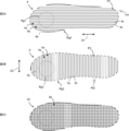
- 2A is a plan view schematically showing a linear structure 4 formed by scanning the linear resin 4b mainly in the first direction D1
- FIG. 2B is a plan view mainly showing the linear resin 5b mainly in the second direction D2.
- FIG. 2C is a plan view schematically showing a linear structure 5 formed by scanning the linear structure 5
- FIG. 2C is a plan view showing a shaped body 10 formed by alternately overlapping the linear structures 4 and the linear structures 5. It is a top view which shows typically. 2A to 2C are common to the embodiments of the first to fourth aspects.
- FIG. 1 is a perspective view schematically showing a structure 1 including a molded body 10 according to an embodiment of the first to fourth aspects.
- 2A is a plan view schematically showing a linear structure 4 formed by scanning the linear resin 4b mainly in the first direction D1
- FIG. 2B
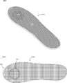
- FIG. 3A is a perspective view of the modeled body 10 having different linear resin thicknesses in the first elastic region Rg1 and the second elastic region Rg2, and FIG. 3B is a top view of the modeled body 10 shown in FIG. 3A.
- FIGS. 3A and 3B are common to the first and second embodiments.
- FIG. 4A is a perspective view schematically illustrating a three-dimensional modeling apparatus 50 for manufacturing the molded body 10 according to the embodiment
- FIG. 4B is a schematic view of a gear mechanism 11A1 provided inside the head 11 illustrated in FIG. 4A. It is. 4A and 4B are common to the first and second embodiments. It is a functional block diagram of control device Cnt which controls three-dimensional modeling device 50.
- FIG. 9 is a perspective view for explaining that the thickness of the linear resin discharged from the nozzle 12 is continuously changed when the linear structure 5 is formed.
- FIG. 3B is a top view of the shaped body 10B in which the arrangement interval of the linear resin is larger than the arrangement interval of the linear resin of the molded body 10 shown in FIGS. 3A and 3B. It is a functional block diagram of control device Cnt which controls three-dimensional modeling device 50. It is a perspective view of the modeled object 10 of the covering layer 3 of the structure 1 according to the embodiment.
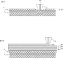
- FIG. 11A is an explanatory diagram of the impregnation layer forming step
- FIG. 11B is an explanatory diagram of the linear structure forming step. It is a perspective view of structure 1 of a 2nd embodiment of the 4th viewpoint of the present invention.
- the structure 1 includes a base material layer 2 and a coating layer 3.
- the structure 1 include those used in the field of nursing (pressure ulcer prevention supporter, foot foot prevention supporter, child cine, etc.), sports use (shoe insole, etc.).
- the structure 1 is provided with a coating layer 3 made of a soft material to enhance the feeling of use.
- the structure 1 is suitable for use in which the coating layer 3 is used in contact with a living body (eg, a human body).
- the structure 1 is an insole of a shoe.
- the base layer 2 is a layer on which the coating layer 3 is formed, and the base layer 2 and the coating layer 3 are in close contact with each other.
- the base layer 2 can be composed of, for example, a foam or a sponge.
- the resin material constituting the base layer 2 is not particularly limited. In the embodiment, an example in which the structure 1 includes the base material layer 2 and the coating layer 3 will be described as an example, but the embodiment is not limited thereto.
- the structure 1 does not have to include the base layer 2.
- the coating layer 3 covers at least a part of the base material layer 2.
- the coating layer 3 is formed of a resin material different from the resin material forming the base layer 2.
- the coating layer 3 is made up of the molded body 10.
- the coating layer 3 is configured from the modeled body 10, and the coating layer 3 does not have a configuration other than the modeled body 10, but the coating layer 3 has a configuration other than the modeled body 10. Is also good.
- the molded body 10 is configured by laminating two types of linear structures (linear structures 4 and 5 described later).
- Linear structures 4, 5 As shown in FIGS. 2A and 2B, the linear structures 4 and 5 are formed of one linear resin 4b and 5b. As shown in FIG. 2A, the linear resin 4b constituting the linear structure 4 extends in the first direction D1, and the linear resin 5b constituting the linear structure 5 extends in the second direction D1 as shown in FIG. 2B. Extends to D2. In the present embodiment, the first direction D1 and the second direction D2 are orthogonal, but the first direction D1 and the second direction D2 do not have to be orthogonal. Further, a plurality of grooves 4a, 5a are formed in the linear structures 4, 5. The groove 4a extends in the first direction D1, and the groove 5a extends parallel to the second direction D2. That is, a pair of adjacent linear portions 4c of the linear resin 4b is spaced, and similarly, a pair of adjacent linear portions 5c of the linear resin 5b is spaced.
- the molded body 10 is a structure having a plurality of linear structures 4 and a plurality of linear structures 5, and the linear structures 4 and the linear structures 5 are alternately stacked. For this reason, as shown in FIGS. 3A and 3B, the modeled body 10 is formed in a mesh shape, and the modeled body 10 has a large number of holes 3a. As a result, the air permeability of the structure 1 is improved, and the elasticity of the coating layer 3 of the structure 1 is improved.
- First and second elastic regions Rg1, Rg2 As shown in FIGS. 3A and 3B, the modeled object 10 has first and second elastic regions Rg1 and Rg2.
- the linear resin forming the first elastic region Rg1 is configured to be thinner than the linear resin forming the second elastic region Rg2.
- the linear structure 4 has first and second elastic regions Rg1 and Rg2, and the linear structure 5 also has first and second elastic regions Rg1 and Rg2.
- the outer edge of the first elastic region Rg1 of the linear structure 4 and the outer edge of the first elastic region Rg1 of the linear structure 5 match.
- the first elastic region Rg1 of the linear structure 4 and the first elastic region Rg1 of the linear structure 5 overlap.
- the edges (outer and inner edges) of the second elastic regions Rg2 of the linear structures 4 and the edges (the outer edges and the inner edges) of the second elastic regions Rg2 of the linear structures 5 overlap so that the outer edge and the inner edge coincide.
- first and second elastic regions Rg1 and Rg2 of the linear structure 4 and the first and second elastic regions Rg1 and Rg2 of the linear structure 5 are overlapped with each other.
- the first and second elastic regions Rg1 and Rg2 extend from the lowermost layer to the uppermost layer of the linear structures 4 and 5.
- the first elastic region Rg1 is disposed inside the second elastic region Rg2. Further, the first elastic region Rg1 and the second elastic region Rg2 are connected so as to be continuous. That is, no intervening region exists between the first elastic region Rg1 and the second elastic region Rg2.
- the three-dimensional printing apparatus 50 includes a head 11, a nozzle 12, a frame 20, a pair of first guide units 21, a second guide unit 22, a table driving unit 30, and a forming table 31. .
- a wire 14 made of resin is inserted into the head 11.
- the three-dimensional printing apparatus 50 includes a first driving unit that moves the head 11 along the second guide unit 22 and a second driving unit that moves the second guide unit 22 to a pair of second guide units 22. And a second drive unit that moves along the direction.
- the first drive unit and the second drive unit correspond to the head drive unit 15 shown in FIG.
- the three-dimensional printing apparatus 50 includes a control device Cnt for controlling various actuators.
- the head 11 is provided on the second guide portion 22, and the head 11 is configured to be movable in the first direction D1.
- a resin supply mechanism 11A and a heater 11B are provided in the head 11.
- the resin supply mechanism 11A is a mechanism for sending out the wire rod 14 inserted into the head 11 to the nozzle 12, and the resin supply mechanism 11A includes a gear mechanism 11A1 (see FIG. 4B) and a motor (not shown) for rotating the gear mechanism. can do.
- the wire 14 is engaged with a gear mechanism of the resin supply mechanism 11 ⁇ / b> A, and the wire mechanism is rotated to send the wire 14 to the nozzle 12.
- the heater 11B is disposed above the nozzle 12.
- the wire 14 is softened, and the softened wire 14 is discharged from the nozzle 12 as a linear resin.
- the mode in which the wire rod 14 is sent out to the nozzle 12 by the gear mechanism 11A1 has been described, but the present invention is not limited to this mode.
- the three-dimensional modeling device 50 may be configured to supply the pellet type resin to the nozzle 12.
- the three-dimensional modeling device 50 may be configured to supply the pellet-shaped resin to the nozzle 12 instead of the gear mechanism 11A1.
- a motor provided to rotate the screw.
- Nozzle 12 is fixed to the lower part of head 11. As the head 11 moves with respect to the second guide portion 22 and the second guide portion 22 moves with respect to the pair of first guide portions 21, the nozzles 12 two-dimensionally scan the modeling table 31.
- the frame 20 supports the pair of first guide portions 21 and second guide portions 22.
- a modeling table 31 is arranged inside the frame 20.
- the table drive unit 30 has a function of moving the modeling table 31 up and down. Each time a linear structure of an arbitrary layer is formed, the table driving unit 30 moves the modeling table 31 downward, so that the three-dimensional modeling apparatus 50 can stack the linear structures.
- the control device Cnt of the three-dimensional printing apparatus 50 acquires target object data relating to an object (in the present embodiment, a human foot) using the structure 1.
- the acquired object data is, for example, pressure distribution data or external shape data.
- the pressure distribution data is data indicating the load applied to the object
- the outer shape data is data indicating the surface shape of the object.
- the control device Cnt includes a calculation unit U1, an operation control unit U2, and a storage unit U3.
- the calculation unit U1 generates molding data for molding the molded body 10 based on the acquired target object data.
- This modeling data includes scanning path data and thickness data.
- the operation control unit U2 controls the head driving unit 15, the table driving unit 30, the resin supply mechanism 11A, and the heater 11B.
- the storage unit U3 stores various data such as modeling data.
- Each functional unit included in the control device Cnt is configured by dedicated hardware or an MPU (Micro Processing Unit) that executes a program stored in the storage unit U3.
- the control device Cnt is dedicated hardware, the control device Cnt is, for example, a single circuit, a composite circuit, an ASIC (application specific integrated circuit), an FPGA (field-programmable gate array), or a combination thereof. Applicable.
- Each of the function units realized by the control device Cnt may be realized by individual hardware, or each function unit may be realized by one piece of hardware.
- each function executed by the control device Cnt is realized by software, firmware, or a combination of software and firmware. Software and firmware are described as programs and stored in the storage unit U3.
- the MPU realizes each function of the control device Cnt by reading and executing the program stored in the storage unit U3.
- the storage unit U3 is, for example, a nonvolatile or volatile semiconductor memory such as a RAM, a ROM, a flash memory, an EPROM, and an EEPROM.
- the scan path data is data that determines the path of the nozzle 12 when the nozzle 12 is two-dimensionally scanned.
- the scanning path data defines, for example, the scanning pitch of the nozzles 12 when the nozzles 12 are two-dimensionally scanned and the coordinates of the nozzles 12 when the nozzles 12 are two-dimensionally scanned.
- the scanning pitch defined by the scanning path data corresponds to the pitch Pt1
- the scanning pitch defined by the scanning path data corresponds to the pitch Pt2.
- the coordinates defined by the scanning path data are, for example, coordinates such as the coordinates P1 of the outer edge of the second elastic region Rg2.
- the coordinates defined by the path data are, for example, coordinates such as the coordinates P2 of the outer edge of the second elastic region Rg2. Further, the coordinates defined by the scan path data include the coordinates defining the boundary between the first elastic region Rg1 and the second elastic region Rg2.
- the scanning path data is described as being changed based on the target object data, but is not limited thereto. Even if the object data is different, the same scan path data may be used.
- the thickness data is associated with the scan path data, and the thickness data is data for determining the thickness of the linear resin discharged from the nozzles 12.
- the thickness of the linear resin discharged from the nozzle 12 can be changed by changing the amount of the wire 14 (the length of the wire 14) sent out from the resin supply mechanism 11A to the nozzle 12 per unit time. That is, when the operation control unit U2 controls the resin supply mechanism 11A, the thickness of the linear resin discharged from the nozzle 12 changes.
- the thickness data corresponds to the control data of the resin supply mechanism 11A.
- the means for changing the thickness of the linear resin discharged from the nozzle 12 is not limited to this.
- the nozzle 12 may be configured such that the opening diameter for discharging the linear resin is variable. That is, the nozzle 12 is provided with a diameter changing mechanism that changes the opening diameter of the nozzle 12, and the operation control unit U2 controls the diameter changing mechanism based on the modeling data.
- the thickness data of the molding data corresponds to the control data of the diameter changing mechanism.
- the linear resin becomes thicker as the opening diameter of the nozzle 12 increases. Further, the thickness of the linear resin discharged from the nozzle 12 can be changed by, for example, changing the scanning speed of the nozzle 12.
- the thickness of the linear resin discharged from the nozzle 12 can be changed by changing the distance that the nozzle 12 scans per unit time.
- the thickness data corresponds to the control data of the head driving unit 15. Note that, as the scanning speed of the nozzle 12 becomes slower, the amount of the linear resin discharged from the nozzle 12 to an arbitrary position also increases. Therefore, as the scanning speed of the nozzle 12 becomes slower, the linear resin becomes thicker.
- the method for manufacturing the structure 1 according to the embodiment includes an acquisition step, a generation step, and a modeling step.
- the control device Cnt acquires target object data from, for example, a measuring device.
- the measuring device corresponds to a device for measuring the pressure distribution of the foot or a device for scanning the outer shape of the foot.
- the calculation unit U1 of the control device Cnt generates the modeling data of the modeling body 10 based on the target object data.
- the generated modeling data includes the scanning path data and the thickness data as described above.
- the scanning path data defines the range of the first and second elastic regions Rg1 and Rg2 in addition to defining the path for scanning the nozzle 12.
- the thickness data associated with the scan path data includes the control data of the resin supply mechanism 11A in the first elastic region Rg1 (the delivery amount of the wire 14) and the control data of the resin supply mechanism 11A in the second elastic region Rg2 (the control data of the resin supply mechanism 11A). (The delivery amount of the wire 14).
- the sending amount of the wire 14 refers to the amount of the wire 14 that the resin supply mechanism 11A sends out to the nozzle 12 per unit time.
- the operation control unit U2 of the control device Cnt controls the head driving unit 15, the table driving unit 30, and the resin supply mechanism 11A based on the modeling data.
- the base material layer 2 that has been manufactured in advance is placed on the modeling table 31.
- the base material layer 2 can also be formed in a forming step.
- the linear resin constituting the linear structures 4 and 5 is composed of one linear resin. That is, when the nozzle 12 performs two-dimensional scanning, the path of the nozzle 12 is drawn with one stroke.
- the shapes of the linear resins 4b and 5b shown in FIGS. 2A and 2B correspond to the paths of the nozzles 12 when the linear structures 4 and 5 are formed in the forming step.
- each component operates as follows. That is, as shown in FIG. 6, when the nozzle 12 passes through a portion of the path of the nozzle 12 that belongs to the second elastic region Rg2, the resin supply mechanism 11A operates so as to increase the amount of wire 14 to be delivered. . Further, when the nozzle 12 passes through a portion belonging to the first elastic region Rg1 in the path of the nozzle 12, the resin supply mechanism 11A operates so as to reduce the amount of wire 14 to be delivered. As a result, the linear resin forming the first elastic region Rg1 becomes thinner than the linear resin forming the second elastic region Rg2.
- the operation control unit U2 controls the table driving unit 30 to form the object.
- the table 31 is moved downward.
- the operation control unit U2 causes the nozzle 12 to scan a path corresponding to the other shape of the linear resin 4b and the linear resin 5b, and the operation control unit U2 controls the table driving unit 30 to form the object.
- the table 31 is moved downward.
- the molded body 10 has first and second elastic regions Rg1 and Rg2, and the linear resin forming the first elastic region Rg1 is thinner than the linear resin forming the second elastic region Rg2. I have. That is, the modeled body 10 has different elasticity (cushioning property) depending on the location, and as a result, the modeled body 10 has a configuration that can enhance the user's feeling of use. Specifically, the first elastic region Rg1 is softer than the second elastic region Rg2 and has more cushioning properties than the second elastic region Rg2. The portion of the elastic region Rg1 is gently received.
- the formation positions of the first and second elastic regions Rg1 and Rg2 shown in FIG. 2A and the like are only examples, and are not limited to the formation positions.
- the scanning pitch when the nozzle 12 is two-dimensionally scanned is the same for the first elastic region Rg1 and the second elastic region Rg2.
- the scanning pitch when the nozzle 12 is two-dimensionally scanned is the pitch Pt1 shown in FIG. 2A in all regions, that is, is constant.
- the scanning pitch when the nozzle 12 is two-dimensionally scanned is the pitch Pt2 shown in FIG. 2B in all regions, that is, is constant.
- the modeling body 10 employs a configuration in which the elasticity (cushioning property) differs depending on the location, the three-dimensional modeling apparatus 50 maintains the scanning pitch when the nozzle 12 is two-dimensionally scanned while keeping the scanning pitch constant.
- the molded object 10 can be formed. For this reason, even if the modeling object 10 employs a configuration having different elasticity (cushioning property) depending on the location, the complexity of the two-dimensional scanning path of the nozzle 12 is suppressed. Therefore, in the case of manufacturing a modeled body having different elasticity (cushioning property) depending on the location, the two-dimensional scanning path is complicated, so that the three-dimensional modeling apparatus cannot model the model or the configuration of the modeled body needs to be changed. Can be avoided.
- the thickness of the linear resin discharged from the nozzle 12 can be changed.
- the manufacturing method of the modeled object 10 according to the embodiment can model a modeled object whose elasticity (cushioning property) changes continuously and smoothly.
- the method for manufacturing the molded body 10 according to the embodiment has advantageous effects. As shown in FIG.
- the linear resin discharged from the nozzle 12 is thinned, and when the nozzle 12 scans the end 5d, the linear resin is discharged from the nozzle 12. Increase the thickness of the linear resin.
- the linear resin discharged from the nozzle 12 is gradually thickened or gradually reduced. Make it thin.
- the outer peripheral portion of the linear structure 5 (corresponding to the outer peripheral portion of the molded body 10) is configured to be hard, and the inner portion of the outer peripheral portion of the linear structure 5 is softened. Can be configured.
- the molded body in the filling rate control method, can be hardened by reducing the arrangement interval of a pair of adjacent linear resins, that is, by increasing the filling rate.
- the arrangement interval between a pair of adjacent linear resins is reduced, the scanning pitch of the nozzles 12 is shortened accordingly, and the scanning time of the nozzles 12 is increased, and as a result, the molding time of the molded body 10 is increased.
- the elasticity cushioning property
- the elasticity can be varied according to each position of the modeled body 10 by changing the thickness of the linear resin discharged from the nozzle 12.
- the molded body 10 can be hardened by increasing the thickness of the linear resin without reducing the arrangement interval of the linear resin. That is, the method of manufacturing the modeled body 10 according to the embodiment can suppress an increase in the modeling time of the modeled body 10 when the modeled body 10 is hardened.
- the method of manufacturing the modeled object 10 according to the embodiment has an advantageous effect. That is, in the manufacturing method of the modeled body 10 according to the embodiment, by changing the thickness of the linear resin discharged from the nozzle 12, the elasticity (cushioning property) can be varied depending on each position of the modeled body 10. Therefore, in the manufacturing method, it is possible to suppress variations of the scan path data stored in the control device Cnt, and to suppress a load when the control device Cnt calculates the scan path data. As described above, the manufacturing method according to the embodiment can reduce the complexity of the processing performed by the control device Cnt when forming the molded body 10, and as a result, the manufacturing method according to the embodiment includes the structure 1 Easy to automate the manufacturing process.
- the elasticity of the first elastic region Rg1 and the elasticity of the second elastic region Rg2 are determined. Although it can be different, it is difficult to compose the path of the nozzle 12 with one stroke. In particular, when the first elastic region Rg1 is arranged inside the second elastic region Rg2 as in the modeled object 10 according to the embodiment, it is more difficult to configure the path of the nozzle 12 with one stroke. Prone.
- the first elastic region Rg1 and the second elastic region Rg2 are separately set. Need to be shaped. If the first elastic region Rg1 and the second elastic region Rg2 are separately formed, the first elastic region Rg1 and the second elastic region Rg2 become discontinuous, so that the first elastic region Rg1 deviates from the second elastic region Rg2. As a result, the feeling of use of the molded body (insole) is deteriorated, which leads to a decrease in the quality of the molded body.
- the molding time of the molded body becomes longer.
- the first elastic region Rg1 and the second elastic region Rg2 are connected so as to be continuous. For this reason, in the molded object 10 according to the embodiment, the deterioration of the quality is suppressed, and the prolongation of the molding time is suppressed.
- Base material layer 2 The description of the base material layer 2 according to the embodiment of the second aspect is given in 1-1. The description is omitted because it is the same as the base material layer 2.
- Coating layer 3 The description of the coating layer 3 of the embodiment of the second aspect is given in 1-2. The description is omitted because it is the same as the coating layer.
- Modeling object 10B The shape of the model of the covering layer 3 is not limited to the model 10 described above.
- the shaped body of the coating layer 3 may be a shaped body 10B shown in FIG.
- the arrangement interval of the linear resin in the first elastic region Rg1 of the modeled object 10B is wider than the arrangement interval of the linear resin in the first elastic region Rg1 of the modeled object 10B. That is, the filling rate of the first elastic region Rg1 of the modeled body 10B is smaller than the filling rate of the first elastic region Rg1 of the modeled body 10.
- the first elastic region Rg1 of the modeled body 10B also has a cushioning-rich configuration, similarly to the first elastic region Rg1 of the modeled body 10.
- the hardness of the shaped body can be changed by changing the thickness of the linear resin as in the shaped body 10, but the filling rate of the linear resin can be changed as in the shaped body 10B, and the hardness of the shaped body can be changed. Can be changed.
- the three-dimensional modeling apparatus 50 is used in the method of manufacturing the structure 1.
- the system for manufacturing the structure 1 includes an acquisition unit, a generation unit, and a modeling unit.
- the three-dimensional printing apparatus 50 corresponds to a printing unit in a system for manufacturing the structure 1.
- the three-dimensional printing apparatus 50 includes a head 11, a nozzle 12, a frame 20, a pair of first guide units 21, a second guide unit 22, a table driving unit 30, and a forming table 31. .
- a wire 14 made of resin is inserted into the head 11.
- the three-dimensional printing apparatus 50 includes a first driving unit that moves the head 11 along the second guide unit 22 and a second driving unit that moves the second guide unit 22 to a pair of second guide units 22. And a second drive unit that moves along the direction.
- the first drive unit and the second drive unit correspond to the head drive unit 15 shown in FIG.
- the three-dimensional printing apparatus 50 includes a control device Cnt for controlling various actuators.
- the control device Cnt of the three-dimensional printing apparatus 50 acquires target object data relating to an object (in the present embodiment, a human foot) using the structure 1.
- the acquired object data is pressure distribution data and outer shape data.
- the pressure distribution data is data indicating the load applied to the object
- the outer shape data is data indicating the surface shape of the object.
- the control device Cnt acquires pressure distribution data from the pressure measurement unit Se1.
- the control device Cnt acquires the outline data from the outline scanning unit Se2.
- the three-dimensional modeling device 50 corresponds to an acquisition unit in a system that manufactures the structure 1, the pressure measurement unit Se1 and the outer shape scanning unit Se2.
- the control device Cnt includes a calculation unit U1, an operation control unit U2, and a storage unit U3.
- the operation unit U1 of the control device Cnt corresponds to a generation unit in a system that manufactures the structure 1.
- the calculation unit U1 generates molding data for molding the molded body 10 based on the acquired target object data.
- This modeling data includes scanning path data and thickness data.
- the operation control unit U2 controls the head driving unit 15, the table driving unit 30, the resin supply mechanism 11A, and the heater 11B.
- the storage unit U3 stores various data such as modeling data.
- each functional unit, scan path data, and thickness data included in the control device Cnt are described in 2-2. Since the content is the same as that described in the functional block of the control device Cnt, the description is omitted. Further, also in the embodiment of the second aspect, as means for changing the thickness of the linear resin discharged from the nozzle 12, 2-2. The contents described in the functional blocks of the control device Cnt can be adopted.
- the method for manufacturing the structure 1 according to the embodiment includes an acquisition step, a generation step, and a modeling step.
- the control device Cnt acquires the pressure distribution data from the pressure measurement unit Se1, and acquires the outer shape data from the outer shape scan unit Se2.
- the control device Cnt acquires the contour data in addition to the pressure distribution data.
- the control device Cnt may not acquire the contour data.
- the calculation unit U1 of the control device Cnt generates modeling data of the modeling bodies 10 and 10B based on the target object data.
- the generated modeling data includes the scanning path data and the thickness data as described above.
- the calculation unit U1 generates modeling data of the modeling bodies 10, 10B based on the pressure distribution data and the outer shape data.
- the control device Cnt stores a program that can determine an insole shape suitable for the user's foot based on the pressure distribution of the target and the outer shape of the target.
- the calculation unit U1 generates modeling data of the modeling bodies 10 and 10B based on the algorithm of the program.
- the algorithm of this program can set an area in the pressure distribution data where the pressure is higher than a predetermined pressure value as the first elastic area Rg1. Also, the algorithm of this program is that if the variation of the pressure value of the pressure distribution data is smaller than a predetermined value and the average of the pressure values of the pressure distribution data is lower than the predetermined pressure value, The filling rate of the resin may be set constant, and the filling rate of the linear resin may be set low. As described above, the algorithm of the program can be determined based on the properties of the target object, the demands of the user, and the like.
- the scanning path data defines a path for scanning the nozzle 12.
- the scan path data defines the range of the first and second elastic regions Rg1 and Rg2.
- the thickness data associated with the scan path data includes the control data of the resin supply mechanism 11A in the first elastic region Rg1 (the delivery amount of the wire 14) and the control data of the resin supply mechanism 11A in the second elastic region Rg2 (the control data of the resin supply mechanism 11A). (The delivery amount of the wire 14).
- the sending amount of the wire 14 refers to the amount of the wire 14 that the resin supply mechanism 11A sends out to the nozzle 12 per unit time.
- the operation control unit U2 of the control device Cnt controls the head driving unit 15, the table driving unit 30, and the resin supply mechanism 11A based on the modeling data.
- the base material layer 2 that has been manufactured in advance is placed on the modeling table 31.
- the base material layer 2 can also be formed in a forming step.
- the structure 1 is modeled based on the modeling data generated in the generation step so that the flexibility (cushioning property) of the structure 1 changes.
- the flexibility (cushioning property) of the structure 1 can be changed by adjusting the thickness of the linear resin (see FIG. 3B) or adjusting the pitch of the linear resin (see FIG. 8).
- the configuration of FIG. 3B and the configuration of FIG. 8 are independent, the structure 1 according to the embodiment has the configuration of the first elastic region Rg1 of FIG. 3B and the configuration of the first elastic region Rg1 of FIG. Both may be provided.
- the linear resin constituting the linear structures 4 and 5 of the molded body 10 is formed of one linear resin. That is, when the nozzle 12 performs two-dimensional scanning, the path of the nozzle 12 is drawn with one stroke.
- the shapes of the linear resins 4b and 5b shown in FIGS. 2A and 2B correspond to the paths of the nozzles 12 when the linear structures 4 and 5 are formed in the forming step.
- each component operates as follows. That is, when the nozzle 12 passes through a portion of the path of the nozzle 12 that belongs to the second elastic region Rg2, the resin supply mechanism 11A operates so as to increase the amount of wire 14 to be delivered. Further, when the nozzle 12 passes through a portion belonging to the first elastic region Rg1 in the path of the nozzle 12, the resin supply mechanism 11A operates so as to reduce the amount of wire 14 to be delivered. As a result, the linear resin forming the first elastic region Rg1 becomes thinner than the linear resin forming the second elastic region Rg2.
- the first elastic region Rg1 of the modeled body 10B is different from the first elastic region Rg1 of the modeled body 10, and a part of the linear resin of the first elastic region Rg1 of the modeled body 10B is interrupted. It is preferable that the nozzle 12 does not discharge the linear resin when the nozzle 12 scans the interrupted portion. Further, the scanning path of the nozzle 12 may be set so as to bypass the interrupted portion so that the nozzle 12 does not scan the interrupted portion.
- the operation control unit U2 controls the table driving unit 30 to form the object.
- the table 31 is moved downward.
- the operation control unit U2 causes the nozzle 12 to scan a path corresponding to the other shape of the linear resin 4b and the linear resin 5b, and the operation control unit U2 controls the table driving unit 30 to form the object.
- the table 31 is moved downward.
- the manufacturing method according to the embodiment and the system according to the embodiment form a structure based on the forming data generated based on the pressure distribution data. That is, in the manufacturing method according to the embodiment and the system according to the embodiment, since the structure is formed in consideration of the pressure distribution indicating the load applied to the object to be formed, the usability of the structure can be enhanced.
- the scanning path data or the thickness data is changed according to the pressure distribution data.
- the generation unit (the operation unit U1) changes the scanning path data or the thickness data according to the pressure distribution data.
- the scan path data the filling rate of the linear resin can be changed, and the elasticity (cushioning property) of the modeled object can be changed.
- the thickness data the elasticity (cushioning property) of the modeled object can be changed.
- the manufacturing method according to the embodiment and the system according to the embodiment use a plurality of methods, that is, a method of changing the filling rate and a method of changing the thickness of the linear resin, to elasticity (cushioning property) of the molded body. Can be changed, it is possible to form the structure 1 according to the properties of the object and the user's request, and as a result, the manufacturing method according to the embodiment and the system according to the embodiment use the structure 1 The feeling can be enhanced.
- the manufacturing method and the system according to the embodiment change the thickness of the linear resin according to the location of the shaped body (see FIGS. 3A and 3B), and the filling rate of the linear resin according to the location of the shaped body. Can be changed (see FIG. 8), and in the manufacturing method and the system according to the embodiment, it is possible to form a shaped body having a different elasticity (cushioning property) depending on a portion like the shaped body 10. For this reason, the manufacturing method and system according to the embodiment can further enhance the usability of the structure 1.
- the molding data is generated based on the pressure distribution data and the outer shape data.
- the generation unit (the operation unit U1) generates the molding data based on the pressure distribution data and the outer shape data. That is, the control device Cnt generates modeling data in consideration of not only the pressure distribution of the object but also the outer shape of the object. For this reason, in the manufacturing method and system according to the embodiment, it is possible to form a shaped body having a shape suitable for an object and a hardness suitable for the object, and as a result, the manufacturing method and the system according to the embodiment In the system, the usability of the structure 1 can be further enhanced.
- the base layer 2 is a layer on which the coating layer 3 is formed, and the base layer 2 and the coating layer 3 are in close contact with each other.
- the base layer 2 is formed of a foam, and the foam of the base layer 2 is formed with bubbles into which the resin constituting the coating layer 3 enters.
- the base material layer 2 can be composed of a foam having a large number of cells, and can also be composed of a sponge having a large number of cells.
- the resin material constituting the base layer 2 is not particularly limited.
- the cell structure of the base layer 2 may be an open cell structure or a closed cell structure. In the open-cell structure, the resin is more likely to enter deeper than in the closed-cell structure, and the strength of the closed-cell structure is higher than in the open-cell structure.
- the coating layer 3 covers at least a part of the base material layer 2.
- the coating layer 3 is formed of a resin material different from the resin material forming the base layer 2.
- the coating layer 3 has a modeled body 10 and an impregnated layer 6. As shown in FIGS. 2A to 2C, the modeled body 10 is configured by stacking two types of linear structures (linear structures 4 and 5).
- Linear structures 4, 5 In the embodiment of the third aspect, the description of the linear structures 4 and 5 is described in 1-2-1 of the embodiment of the first aspect. The description is omitted because it is the same as the linear structures 4 and 5.
- Impregnation layer 6 The resin constituting the impregnation layer 6 is impregnated in the base material layer 2. Specifically, in the present embodiment, since the base material layer 2 is a foam, the resin constituting the impregnation layer 6 is contained in the cells of the foam of the base material layer 2. As described above, by impregnating the resin constituting the impregnation layer 6 into the base material layer 2, the resin constituting the impregnation layer 6 becomes entangled with the foam constituting the base material layer 2, and as a result, the impregnation layer 6 It is firmly bonded to the base material layer 2.
- the resin material forming the impregnated layer 6 is the same as the resin material forming the shaped body 10.
- the impregnated layer 6 and the molded body 10 are firmly bonded.
- the coating layer 3 is prevented from peeling off from the base layer 2.
- the position of the surface of the impregnation layer 6 substantially coincides with the surface of the base material layer 2, but the surface of the impregnation layer 6 may protrude from the surface of the base material layer 2.
- the method of manufacturing the structure 1 according to the embodiment includes an impregnation layer forming step and a linear structure forming step.
- the three-dimensional modeling apparatus of the method of manufacturing the structure 1 according to the embodiment includes a nozzle 12, a heating unit (not shown), and a resin supply unit (not shown).
- the nozzle 12 has a function of linearizing the resin supplied from the resin supply unit.
- the heating means is attached to, for example, the nozzle 12, and the resin supplied to the nozzle 12 is softened by the heat of the heating means.
- the linear resin Rs is discharged from the nozzle 12 into the base layer 2 while the nozzle 12 for discharging the linear resin Rs is pushed into the base layer 2.
- the linear resin Rs corresponds to the linear resin 4b or the linear resin 5b shown in FIGS. 2A to 2C.
- the linear resin Rs discharged from the nozzle 12 enters the bubbles of the base layer 2, so that the linear resin Rs is entangled with the foam constituting the base layer 2. That is, the impregnation layer 6 and the base material layer 2 have an anchor effect. As described above, in the embodiment, the impregnated layer 6 is firmly bonded to the base layer 2 by the anchor effect, and the adhesion between the impregnated layer 6 and the base layer 2 is improved.
- the nozzle 12 is two-dimensionally scanned. Specifically, the two-dimensional scanning range of the nozzle 12 in the impregnation layer forming step is determined according to the shape of the lowermost linear structure Bd of the modeled object 10.
- the linear structure Bd corresponds to the linear structure 4 or the linear structure 5 shown in FIGS. 2A to 2C.
- the linear structure Bd in the lowermost layer of the modeling body 10 is the linear structure 4
- the linear structure Bd in the layer immediately above the linear structure Bd in the lowermost layer is a linear structure.
- Body 5 is the linear structure Bd in the layer immediately above the linear structure Bd in the lowermost layer.
- the two-dimensional scanning range of the nozzle 12 in the impregnation layer forming step (hereinafter, referred to as a first range) is the two-dimensional scanning range of the nozzle 12 in the lowermost linear structure Bd of the modeled object 10. (Hereinafter, referred to as a second range) or is preferably wider than the second range so as to include the entire second range. Thereby, the entire lower part of the modeled body 10 is formed on the impregnated layer 6, and peeling of the modeled body 10 from the base layer 2 is more reliably suppressed.
- the second range may protrude from the first range.
- the adhesion between the coating layer 3 and the base material layer 2 is reduced as compared with the portion that does not protrude.
- the adhesion between the coating layer 3 and the base material layer 2 is high in the portions that do not protrude, the effect of suppressing the coating layer 3 from being peeled off from the base material layer 2 is obtained.
- the trajectory of the tip of the nozzle 12 when forming the impregnation layer 6 may be similar to the trajectory of the tip of the nozzle 12 when forming the lowermost linear structure Bd of the modeled object 10.
- the first area of the base layer 2 is not completely covered with the impregnated layer 6, and the ventilation between the holes 3 a of the cover layer 3 and the bubbles of the base layer 2 is blocked by the impregnated layer 6.
- the air permeability of the structure 1 is improved.
- the pressing amount Dp which is the amount of pressing the nozzle 12 into the base material layer 2
- the thickness of the linear resin Rs is the same as the lamination pitch of the linear structure Bd.
- the linear resin Rs discharged from the nozzle 12 not only easily enters the base material layer 2, but also the linear resin Rs discharged from the nozzle 12 enters deeper into the base material layer 2. Therefore, the anchor effect is enhanced, and the impregnated layer 6 is more strongly bonded to the base material layer 2.
- the resin that has entered the base material layer 2 may sometimes spread too much laterally.
- the resin of the adjacent two-dimensional scan path comes into contact. Sometimes. When the resins of the adjacent two-dimensional scanning paths come into contact with each other, the first area of the base material layer 2 is covered with the impregnated layer 6, and the air permeability of the structure 1 is reduced.
- each linear resin Rs constituting each linear structure Bd is composed of one linear resin.
- the trajectory of the tip of the nozzle 12 when the nozzle 12 performs two-dimensional scanning is drawn in a single stroke.
- the linear resin is discharged from the nozzle to the base material layer with the nozzle spaced from the base material layer. Therefore, in the conventional manufacturing method, the resin discharged from the nozzle hardly impregnates the base material layer, and the anchor effect cannot be obtained.
- the structure 1 according to the embodiment when the nozzle 12 is pushed into the base layer 2, the linear resin Rs discharged from the nozzle 12 enters the bubbles of the base layer 2 and solidifies. .
- the resin that has become the impregnated layer 6 by solidification is entangled with the foam constituting the base layer 2, and the impregnated layer 6 and the base layer 2 have an anchor effect. Due to this anchor effect, the impregnated layer 6 is firmly bonded to the base material layer 2, and the adhesion between the impregnated layer 6 and the base material layer 2 is improved.
- a manufacturing method using a three-dimensional modeling apparatus is different from a manufacturing method using a mold (for example, a manufacturing method using injection molding).
- the time required to complete one structure increases. Therefore, it is conceivable to prepare the base layer 2 by injection molding in advance, and to form the molded body 10 on the base layer 2 with a three-dimensional forming apparatus.
- the resin material forming the base layer 2 and the resin material forming the molded body 10 are the same, the base layer 2 and the molded body 10 are easily brought into close contact by the means.
- the resin material forming the base layer 2 may be different from the resin material forming the molded body 10.
- the manufacturing method according to the embodiment to the base material layer 2 manufactured by injection molding in advance. Thereby, even if the resin material forming the base material layer 2 and the resin material forming the molded body 10 are different, it is possible to efficiently manufacture structures having various shapes which are difficult to manufacture by injection molding or the like. it can.
- the base material layer 2 is a layer formed of a shape memory material including a shape memory polymer.
- the shape memory material is a material having shape memory characteristics, and has a characteristic of being restored to an original shape by elasticity when heated to a predetermined recovery temperature or higher.
- the shape memory material preferably includes only the shape memory polymer, but may include another component as long as the shape memory characteristics are not impaired.
- Components other than the shape memory polymer include resins such as polyolefins such as polyethylene and polypropylene, and fillers.
- the proportion of the shape memory polymer in the shape memory material is, for example, 50 to 100% by mass, and specifically, for example, 50, 55, 60, 65, 70, 75, 80, 85, 90, 95, 100% by mass. And may be in a range between any two of the numerical values exemplified here.
- the recovery temperature of the shape memory material usually matches the glass transition temperature of the shape memory polymer.
- Shape memory polymer has the property of returning to its original shape by elasticity when heated to a temperature exceeding Tg.
- Tg is, for example, 35 to 100 ° C., preferably 40 to 75 ° C., and specifically, for example, 35, 40, 45, 50, 55, 60, 65, 70, 75, 80, 85, 90 , 95, and 100 ° C., and may be in a range between any two of the numerical values exemplified here.
- a secondary shape When a secondary shape is formed by applying an external force at a temperature exceeding Tg, and cooling to a temperature below Tg while maintaining the external force, the secondary shape is fixed. At a temperature lower than Tg, the material does not return to its original shape even when the external force is removed.
- the shape memory polymer provided with the secondary shape is heated to a temperature exceeding Tg so that no external force is applied, the shape memory polymer returns to the original shape by elasticity.
- the original shape can be set, for example, by melting a shape memory polymer and molding it into a desired shape.
- the shape memory polymer include polymers having rubber elasticity, such as polynorbornene, trans polyisoprene, styrene-butadiene copolymer, and polyurethane.
- Shape memory polymers and shape memory materials containing the same have the property that the elastic modulus changes significantly near Tg.
- the value of the elastic modulus at (Tg ⁇ 20 ° C.) / The elastic modulus at (Tg + 20 ° C.) is 10 or more.
- the structure 1 is deformed at a temperature equal to or higher than (Tg + 20 ° C.)
- the structure 1 can be used at a temperature of 20 ° C. or lower. For this reason, the shape of the structure can be easily changed to a shape set for each user, and the shape can be maintained during use.
- the value of the elastic modulus at (Tg ⁇ 20 ° C.) / The elastic modulus at (Tg + 20 ° C.) is, for example, 10 to 1000, and specifically, for example, 10, 20, 30, 40, 50, 60, 70, 80, 90, 100, 200, 300, 400, 500, 1000 and may be in the range between any two of the numerical values exemplified here.
- the slope of the graph at Tg is, for example, ⁇ 1 to ⁇ 0. 025, preferably -0.5 to -0.1.
- the value of this slope is, for example, -1, -0.9, -0.8, -0.7, -0.6, -0.5, -0.4, -0.3, -0.2, -0.1, -0.075, -0.050, -0.025, and may be in the range between any two of the numerical values exemplified here.
- a slope of -1 in the graph means that the elastic modulus becomes 10 times when the temperature decreases by 1 ° C
- a slope of -0.025 in the graph means that the elastic modulus increases by a temperature decrease of 40 ° C. Means 10 times.
- X is preferably 20 or less, for example, 0.5 to 20, and specifically, for example, 0.5, 1, 2, 3, 4, 5, 6, 7, 8, 9, 10, 11, 12, 13, 14, 15, 16, 17, 18, 19, 20 and are exemplified here. It may be in the range between any two of the numerical values.
- the elastic modulus means a storage elastic modulus determined by a dynamic viscoelasticity test, and can be measured according to JIS K7244.
- the base layer 2 is formed of a thermoplastic resin other than the shape memory material, it is possible to reduce the elastic modulus of the base layer as the temperature rises.
- a plastic resin since the decrease in the elastic modulus due to a rise in temperature is usually gradual, it is easy to perform an operation of raising the temperature of the base material layer 2 to deform it, and then lowering the temperature to maintain the deformed shape. Therefore, the base material layer 2 needs to be formed of a shape memory material.
- the coating layer 3 covers at least a part of the base material layer 2.
- the coating layer 3 is formed of a soft material.
- the soft material is a material that can be easily elastically deformed at room temperature, and an example is an elastomer having a Tg lower than room temperature. Examples of the elastomer include a styrene-based elastomer.
- the Tg of the soft material is preferably 20 ° C. or lower, more preferably 10 ° C. or lower, and further preferably 0 ° C. or lower.
- the soft material is preferably softer than the shape memory material at room temperature (25 ° C.), and preferably has a lower elastic modulus than the shape memory material at room temperature.
- the usability of the structure 1 is improved by covering the base layer 2 with a covering layer 3 formed of a soft material at a portion that comes into contact with the user.
- the method for manufacturing the structure 1 is not particularly limited, and can be formed by a method such as injection molding or 3D printer modeling.
- the base layer 2 and the coating layer 3 can be integrally formed by two-color molding using a shape memory material and a soft material.
- one of the base layer 2 and the coating layer 3 may be formed by injection molding, and the other may be formed thereon by 3D printer modeling.
- both the base layer 2 and the coating layer 3 may be formed by 3D printer modeling.
- the structure 1 can be formed so as to have a shape set for each user, it is preferable that at least one of the base layer 2 and the coating layer 3 is formed by 3D printer modeling.
- a linear resin formed by extruding a molten resin from a head is two-dimensionally scanned as shown in FIGS. 2A to 2B to form linear structures 4 and 5, and a linear structure is formed.
- a molded object can be formed by laminating 4 and 5.
- the resin may be supplied to the head in the form of a filament or in the form of a pellet. In the latter case, a linear resin can be used even for a soft material that is difficult to form a filament.
- the linear structures 4 and 5 are formed by two-dimensionally scanning the linear resins 4b and 5b in one stroke.
- the linear structure 4 is a linear structure formed by scanning the linear resin 4b mainly in the horizontal direction
- the linear structure 5 is formed by scanning the linear resin 5b mainly in the vertical direction. It is a formed linear structure.
- a shaped body 10 having a lattice shape in plan view is obtained as shown in FIG. 2C.
- the base layer 2 is obtained as the molded body 10.
- the coating layer 3 is obtained as the shaped body 10.
- each of the linear structures 4 and 5 has a plurality of grooves 4a and 5a extending in parallel.
- the groove 4a is formed by the linear resin 4b constituting the linear structure 4 extending in parallel.
- the groove 5a is formed by the linear resin 5b constituting the linear structure 5 extending in parallel.
- one groove 4a of two linear structures 4 and 5 adjacent in the stacking direction intersects the other groove 5a.
- the grooves 4a and 5a are orthogonal, but the grooves 4a and 5a may intersect at an angle other than a right angle.
- the molded body having such a structure is relatively lightweight because of the space inside. Further, when the modeled body is the covering layer 3, the covering layer 3 is easily deformed due to the space inside the covering layer 3, and the cushioning property of the covering layer 3 is improved.
- the physical properties of the molded body are changed by changing the two-dimensional shape of the linear structures 4 and 5 and the diameter and density (the number per unit area) of the linear resins 4b and 5b constituting the linear structures 4 and 5.
- the coating layer 3 can be made more flexible by reducing the diameter of the linear resins 4b and 5b or reducing the density of the linear resins 4b and 5b.
- the densities and patterns of the linear resins 4b and 5b are uniform throughout the linear structures 4 and 5, but the physical properties of the molded body can be changed by partially changing the densities and patterns. Can also be changed.
- the base layer 2 and the coating layer 3 are formed by 3D printing, it is possible to appropriately change the physical properties of the structure 1 according to the needs of the user.
- the base layer 2 may be formed first, and the cover layer 3 may be formed using the base layer 2 as a base. May be formed first, and the base layer 2 may be formed using the coating layer 3 as a base. As will be described later in Examples, the former is preferable because the adhesion between the base material layer 2 and the coating layer 3 becomes better.
- the base layer 2 when the base layer 2 is formed using the coating layer 3 as a base, increasing the temperature of the linear resin when forming the base layer 2 can improve the adhesion between the base layer 2 and the coating layer 3. it can.
- the shape memory material since the shape memory material may be easily deteriorated at a high temperature, it is desirable to lower the temperature of the linear resin when forming the base layer 2 as much as possible. Therefore, by setting the temperature of the linear resin when forming the lowermost layer of the base material layer 2 to be higher than the average temperature of the linear resin when forming the remaining layers of the base material layer 2, In addition, it is possible to suppress the deterioration of the shape memory material while improving the adhesion.
- FIG. 1 A second embodiment of the present invention will be described with reference to FIG. This embodiment is similar to the first embodiment, and is different from the first embodiment in that a skin material 7 is provided. Hereinafter, the differences will be mainly described.
- the skin material 7 is formed on the coating layer 3.
- the skin material 7 is formed of a nonwoven fabric or the like.
- the skin material 7 may be attached to the coating layer 3 after forming a structure in which the base material layer 2 and the coating layer 3 are laminated, and the coating layer 3 and the base material layer 2 are arranged in this order with the skin material 7 as a base.
- a 3D printer may be formed. The latter case is preferable because the labor for attaching the skin material 7 is unnecessary and the adhesion between the skin material 7 and the coating layer 3 is high.
- the structure 1 was manufactured by 3D printer modeling using a shape memory material and a soft material.
- a shape memory material for forming the base material layer 2 a shape memory polymer made of polyurethane (manufactured by SMP Technologies, grade name: MM5520, optimum forming temperature: 215 ° C, Tg: 55 ° C) was used.
- a soft material for forming the coating layer 3 a styrene-based thermoplastic elastomer (manufactured by Kuraray, grade name: Arneston JS20N, optimum molding temperature: 238 ° C.) was used.
- As the skin material 7 a nonwoven fabric made of PET was used.
- the “molding temperature” in the following description is a set temperature of a head that discharges a linear resin during molding.
- Example 1 The base layer 2 was formed at a modeling temperature of 215 ° C., and the coating layer 3 was formed at a modeling temperature of 238 ° C. using the base layer 2 as a base. The bondability between the base material layer 2 and the coating layer 3 was good.
- Example 2 The coating layer 3 was formed at a modeling temperature of 238 ° C. using the skin material 7 as a base, and the base layer 2 was formed at a modeling temperature of 215 ° C. using the coating layer 3 as a base. The bonding property between the skin material 7 and the coating layer 3 was good. The bonding force at the interface between the coating layer 3 and the base material layer 2 was poor.
- Example 3 Using the skin material 7 as a base, the coating layer 3 was formed at a molding temperature of 238 ° C., and the base layer 2 was formed using the coating layer 3 as a base. The molding temperature at the time of forming the lowermost layer of the base material layer 2 was 238 ° C., and the molding temperature at the time of forming the remaining layers was 215 ° C. The bonding property between the skin material 7 and the coating layer 3 and the bonding property between the coating layer 3 and the base material layer 2 were both good.
Landscapes
- Engineering & Computer Science (AREA)
- Chemical & Material Sciences (AREA)
- Materials Engineering (AREA)
- Manufacturing & Machinery (AREA)
- Mechanical Engineering (AREA)
- General Engineering & Computer Science (AREA)
- Life Sciences & Earth Sciences (AREA)
- Physics & Mathematics (AREA)
- Optics & Photonics (AREA)
- Wood Science & Technology (AREA)
- Textile Engineering (AREA)
- Biophysics (AREA)
Abstract
弾性が異なる領域を有していても、造形時のノズル(12)の走査パスの複雑化が抑制される構造体(1)と、弾性が異なる領域を有する構造体(1)の造形にあたり、造形時のノズル(12)の走査パスの複雑化を抑制することができる構造体(1)の製造方法と、を提供することを目的としている。造形体(10)を備え、造形体(10)が線状構造体(4、5)を有し、線状構造体(4、5)が線状樹脂によって形成されている、構造体(1)であって、造形体(10)は、第1及び第2弾性領域(Rg1、Rg2)を有し、第1弾性領域(Rg1)を構成する前記線状樹脂は、第2弾性領域(Rg2)を構成する前記線状樹脂よりも細く構成されている、構造体(1)が提供される。
Description
本発明は、構造体、構造体の製造方法、構造体を製造するシステムに関する。
(第1観点)
従来から、3次元造形装置によって、例えば靴のインソールといった構造体を製造する技術が提案されている(例えば、特許文献1参照)。特許文献1では、足の3次元造形データに基づいて、3次元造形装置によってインソールを造形する。また、特許文献1には外反母趾による痛みを抑制するために3次元造形データに補正を加えることが開示されている。このように、従来から、ユーザーの使用感を高めるために3次元造形データに補正を加える技術が提案されている。
従来から、3次元造形装置によって、例えば靴のインソールといった構造体を製造する技術が提案されている(例えば、特許文献1参照)。特許文献1では、足の3次元造形データに基づいて、3次元造形装置によってインソールを造形する。また、特許文献1には外反母趾による痛みを抑制するために3次元造形データに補正を加えることが開示されている。このように、従来から、ユーザーの使用感を高めるために3次元造形データに補正を加える技術が提案されている。
ここで、構造体の使用感を高める手法には、構造体の各箇所に応じて構造体の弾性を変える手法がある。ここで、構造体の弾性(クッション性)は構造体の硬さや柔らかさを示す指標である。構造体の弾性を変える手法には、構造体の各箇所に応じて樹脂材料を変える第1手法の他に、構造体の各箇所に応じて構造体を構成する線状樹脂の配置間隔(充填率)を変える第2手法(以下、充填率コントロール手法と称する)もある。
(第2観点)
従来から、3次元造形装置によって、例えば靴のインソールといった構造体を製造する技術が提案されている(例えば、特許文献1参照)。特許文献1では、足の3次元造形データに基づいて、3次元造形装置によってインソールを造形する。
従来から、3次元造形装置によって、例えば靴のインソールといった構造体を製造する技術が提案されている(例えば、特許文献1参照)。特許文献1では、足の3次元造形データに基づいて、3次元造形装置によってインソールを造形する。
(第3観点)
3次元造形装置には、線状樹脂(フィラメント)をノズルから基材層へ吐出することで基材層に線状構造体を積層し、基材層上に線状構造体を有する被覆層を形成するものが各種提案されている(例えば、特許文献2参照)。特許文献2の3次元造形装置では、ノズルが基材層に対して間隔をあけた状態で、線状樹脂がノズルから基材層へ吐出される。
3次元造形装置には、線状樹脂(フィラメント)をノズルから基材層へ吐出することで基材層に線状構造体を積層し、基材層上に線状構造体を有する被覆層を形成するものが各種提案されている(例えば、特許文献2参照)。特許文献2の3次元造形装置では、ノズルが基材層に対して間隔をあけた状態で、線状樹脂がノズルから基材層へ吐出される。
ここで、基材層の構成材料と被覆層の樹脂材料とを変えることで、様々な機能をもたせた構造体を3次元造形装置で製造することができる。例えばシューズのインソールを製造する場合には、インソールの上面側の部分を柔らかめの樹脂で構成し、また、インソールの下面側の部分を硬めの樹脂で構成することがある。このようにインソールを構成することで、インソールの上面側の部分では人間の荷重がやさしく受け止められ、また、インソールの下面側の部分ではインソールの型崩れを抑制する。
(第4観点)
特許文献3には、弾性を有する樹脂材で形成された外層部と、荷重印加時に変形しかつ該荷重が印加されなくなったときに形状を保持する材料からなる内層部を備えたことを特徴とするクッション材が開示されている。特許文献3のクッション材は、上記構成を有するので、形状を保ちつつ柔軟性も確保できるという効果を有する。
特許文献3には、弾性を有する樹脂材で形成された外層部と、荷重印加時に変形しかつ該荷重が印加されなくなったときに形状を保持する材料からなる内層部を備えたことを特徴とするクッション材が開示されている。特許文献3のクッション材は、上記構成を有するので、形状を保ちつつ柔軟性も確保できるという効果を有する。
(第1観点)
3次元造形装置の造形方式には、線状樹脂を吐出するノズルを走査させることで構造体を造形する方式がある。このような方式の3次元造形装置を用い、充填率コントロール手法によって構造体の造形を行う場合には、線状樹脂の配置間隔が第1配置間隔である第1弾性領域と、線状樹脂の配置間隔が第2配置間隔である第2弾性領域とで、ノズルの走査ピッチが異なる。このため、上述の方式の3次元造形装置を用い、充填率コントロール手法によって構造体の造形を行う場合には、ノズルを走査させるときのパスが複雑化する場合がある。
3次元造形装置の造形方式には、線状樹脂を吐出するノズルを走査させることで構造体を造形する方式がある。このような方式の3次元造形装置を用い、充填率コントロール手法によって構造体の造形を行う場合には、線状樹脂の配置間隔が第1配置間隔である第1弾性領域と、線状樹脂の配置間隔が第2配置間隔である第2弾性領域とで、ノズルの走査ピッチが異なる。このため、上述の方式の3次元造形装置を用い、充填率コントロール手法によって構造体の造形を行う場合には、ノズルを走査させるときのパスが複雑化する場合がある。
本発明はこのような事情に鑑みてなされたものであり、弾性が異なる領域を有していても、造形時のノズルの走査パスの複雑化が抑制される構造体と、弾性が異なる領域を有する構造体の造形にあたり、造形時のノズルの走査パスの複雑化を抑制することができる構造体の製造方法と、を提供することを目的としている。
(第2観点)
構造体が例えば人体に身につけられるものである場合には、構造体のどの箇所にどの程度の圧力が加わるかを把握した上で、構造体を造形することで構造体の使用感を高めることができる。特許文献1の3次元造形装置は足の3次元造形データを取得するが、特許文献1の技術では使用感の向上に制約が生じやすい。特許文献1の技術では、例えば体重が異なるけれども足の形が同様である2人の人体に対し、同様の形状の構造体(インソール)が造形されることになる。たとえ足の形が同様であっても、体重が大きい方の人体に対しては、弾性(クッション性)が例えば高めの構造体を造形する方が好ましい場合がある。
構造体が例えば人体に身につけられるものである場合には、構造体のどの箇所にどの程度の圧力が加わるかを把握した上で、構造体を造形することで構造体の使用感を高めることができる。特許文献1の3次元造形装置は足の3次元造形データを取得するが、特許文献1の技術では使用感の向上に制約が生じやすい。特許文献1の技術では、例えば体重が異なるけれども足の形が同様である2人の人体に対し、同様の形状の構造体(インソール)が造形されることになる。たとえ足の形が同様であっても、体重が大きい方の人体に対しては、弾性(クッション性)が例えば高めの構造体を造形する方が好ましい場合がある。
本発明はこのような事情に鑑みてなされたものであり、構造体の使用感を高めることができる構造体の製造方法及び構造体を製造するシステムを提供することを目的としている。
(第3観点)
基材層の構成材料と被覆層の樹脂材料とが異なると、被覆層が基材層から剥がれやすくなってしまう場合がある。特に、特許文献2の技術のように、ノズルが基材層に対して間隔をあけた状態で、線状樹脂がノズルから基材層へ吐出される場合には、被覆層全体が基材層の表面上に形成されることになり、被覆層が基材層から剥がれやすくなる。
基材層の構成材料と被覆層の樹脂材料とが異なると、被覆層が基材層から剥がれやすくなってしまう場合がある。特に、特許文献2の技術のように、ノズルが基材層に対して間隔をあけた状態で、線状樹脂がノズルから基材層へ吐出される場合には、被覆層全体が基材層の表面上に形成されることになり、被覆層が基材層から剥がれやすくなる。
本発明はこのような事情に鑑みてなされたものであり、被覆層が基材層から剥がれてしまうことが抑制される構造体及び構造体の製造方法を提供することを目的としている。
(第4観点)
ところで、クッション材の用途によっては、利用者ごとに最適形状を設定し、使用中にはその最適形状がくずれないことが好ましい場合がある。特許文献3のクッション材の内層部は、荷重印加時に変形してしまうので、このような用途には用いることができない。
ところで、クッション材の用途によっては、利用者ごとに最適形状を設定し、使用中にはその最適形状がくずれないことが好ましい場合がある。特許文献3のクッション材の内層部は、荷重印加時に変形してしまうので、このような用途には用いることができない。
本発明はこのような事情に鑑みてなされたものであり、利用者ごとに設定された形状に容易に変形させることができ、かつその形状が使用時には維持され、しかも、使用感が優れた構造体を提供するものである。
(第1観点)
本発明によれば、造形体を備え、造形体が線状構造体を有し、線状構造体が線状樹脂によって形成されている、構造体であって、造形体は、第1及び第2弾性領域を有し、第1弾性領域を構成する前記線状樹脂は、第2弾性領域を構成する前記線状樹脂よりも細く構成されている、構造体が提供される。
本発明によれば、造形体を備え、造形体が線状構造体を有し、線状構造体が線状樹脂によって形成されている、構造体であって、造形体は、第1及び第2弾性領域を有し、第1弾性領域を構成する前記線状樹脂は、第2弾性領域を構成する前記線状樹脂よりも細く構成されている、構造体が提供される。
本発明によれば、第1弾性領域を構成する前記線状樹脂は、第2弾性領域を構成する前記線状樹脂よりも細く構成されている。このため、第1弾性領域の弾性と第2弾性領域の弾性とを異ならせたとしても、第1弾性領域の線状樹脂の配置間隔と第2弾性領域の線状樹脂の配置間隔とを変える必要がなくなり、その結果、本発明に係る構造体は、造形時のノズルの走査パスの複雑化が抑制される。
以下、本発明の種々の実施形態を例示する。以下に示す実施形態は互いに組み合わせ可能である。
好ましくは、前記造形体は、前記線状構造体が積層されて構成され、第1及び第2弾性領域は、前記線状構造体の最下層から最上層にかけて延びており、第1弾性領域と第2弾性領域とが、連続するように繋がっている、構造体が提供される。
実施形態に係る製造方法は、線状樹脂を吐出するノズルを備えた3次元造形装置を用いる、構造体の製造方法であって、造形ステップを備え、前記造形ステップでは、前記ノズルを走査させながら前記ノズルから前記線状樹脂を吐出させることで造形体を形成し、前記造形ステップを行っているときにおいて、前記ノズルから吐出する前記線状樹脂の太さを変化させる、方法が提供される。
好ましくは、前記造形体は、前記線状構造体が積層されて構成され、第1及び第2弾性領域は、前記線状構造体の最下層から最上層にかけて延びており、第1弾性領域と第2弾性領域とが、連続するように繋がっている、構造体が提供される。
実施形態に係る製造方法は、線状樹脂を吐出するノズルを備えた3次元造形装置を用いる、構造体の製造方法であって、造形ステップを備え、前記造形ステップでは、前記ノズルを走査させながら前記ノズルから前記線状樹脂を吐出させることで造形体を形成し、前記造形ステップを行っているときにおいて、前記ノズルから吐出する前記線状樹脂の太さを変化させる、方法が提供される。
(第2観点)
本発明によれば、3次元造形装置を用いた、構造体の製造方法であって、取得ステップと、生成ステップと、造形ステップと、を備え、前記3次元造形装置は、線状樹脂を吐出するノズルを有し、前記取得ステップでは、造形する対象物にかかる負荷を示す圧力分布データを取得し、前記生成ステップでは、前記圧力分布データに基づいて前記構造体の造形データを生成し、前記造形ステップでは、前記造形データに基づいて前記ノズルを走査させて前記構造体を造形する、方法が提供される。
本発明によれば、3次元造形装置を用いた、構造体の製造方法であって、取得ステップと、生成ステップと、造形ステップと、を備え、前記3次元造形装置は、線状樹脂を吐出するノズルを有し、前記取得ステップでは、造形する対象物にかかる負荷を示す圧力分布データを取得し、前記生成ステップでは、前記圧力分布データに基づいて前記構造体の造形データを生成し、前記造形ステップでは、前記造形データに基づいて前記ノズルを走査させて前記構造体を造形する、方法が提供される。
本発明によれば、圧力分布データに基づいて生成された造形データに基づき、構造体を造形するので、構造体の使用感を高めることができる。
以下、本発明の種々の実施形態を例示する。以下に示す実施形態は互いに組み合わせ可能である。
好ましくは、前記造形データは、走査パスデータと、太さデータとを有し、前記走査パスデータは、前記ノズルを2次元走査させるときの走査ピッチを定め、前記太さデータは、前記走査パスデータに関連付けられており、且つ、前記ノズルから吐出する前記線状樹脂の太さを定め、前記生成ステップでは、前記圧力分布データに応じて前記走査パスデータ又は前記太さデータを変える、方法が提供される。
好ましくは、前記取得ステップでは、前記対象物の外形データを更に取得し、前記生成ステップでは、前記圧力分布データ及び前記外形データに基づいて、前記造形データを生成する、方法が提供される。
好ましくは、前記造形ステップでは、前記造形データに基づいて前記構造体の柔軟性が変化するように、前記構造体を造形する、方法が提供される。
実施形態に係るシステムは、構造体を製造するシステムであって、取得部と、生成部と、造形部と、を備え、前記造形部は、3次元造形装置を有し、前記3次元造形装置は、線状樹脂を吐出するノズルを有し、前記取得部は、造形する対象物にかかる負荷を示す圧力分布データを取得し、前記生成部は、前記圧力分布データに基づいて前記構造体の造形データを生成し、前記造形部は、前記造形データに基づいて前記ノズルを走査させて前記構造体を造形する、システムが提供される。
好ましくは、前記造形データは、走査パスデータと、太さデータとを有し、前記走査パスデータは、前記ノズルを2次元走査させるときの走査ピッチを定め、前記太さデータは、前記走査パスデータに関連付けられており、且つ、前記ノズルから吐出する前記線状樹脂の太さを定め、前記生成部は、前記圧力分布データに応じて前記走査パスデータ又は前記太さデータを変える、システムが提供される。
好ましくは、前記造形部は、前記造形データに基づいて前記構造体の柔軟性が変化するように、前記構造体を造形する、システムが提供される。
好ましくは、前記造形データは、走査パスデータと、太さデータとを有し、前記走査パスデータは、前記ノズルを2次元走査させるときの走査ピッチを定め、前記太さデータは、前記走査パスデータに関連付けられており、且つ、前記ノズルから吐出する前記線状樹脂の太さを定め、前記生成ステップでは、前記圧力分布データに応じて前記走査パスデータ又は前記太さデータを変える、方法が提供される。
好ましくは、前記取得ステップでは、前記対象物の外形データを更に取得し、前記生成ステップでは、前記圧力分布データ及び前記外形データに基づいて、前記造形データを生成する、方法が提供される。
好ましくは、前記造形ステップでは、前記造形データに基づいて前記構造体の柔軟性が変化するように、前記構造体を造形する、方法が提供される。
実施形態に係るシステムは、構造体を製造するシステムであって、取得部と、生成部と、造形部と、を備え、前記造形部は、3次元造形装置を有し、前記3次元造形装置は、線状樹脂を吐出するノズルを有し、前記取得部は、造形する対象物にかかる負荷を示す圧力分布データを取得し、前記生成部は、前記圧力分布データに基づいて前記構造体の造形データを生成し、前記造形部は、前記造形データに基づいて前記ノズルを走査させて前記構造体を造形する、システムが提供される。
好ましくは、前記造形データは、走査パスデータと、太さデータとを有し、前記走査パスデータは、前記ノズルを2次元走査させるときの走査ピッチを定め、前記太さデータは、前記走査パスデータに関連付けられており、且つ、前記ノズルから吐出する前記線状樹脂の太さを定め、前記生成部は、前記圧力分布データに応じて前記走査パスデータ又は前記太さデータを変える、システムが提供される。
好ましくは、前記造形部は、前記造形データに基づいて前記構造体の柔軟性が変化するように、前記構造体を造形する、システムが提供される。
(第3観点)
本発明によれば、基材層と、被覆層とを備える構造体であって、前記被覆層は、線状構造体と、含浸層とを有し、且つ、前記被覆層は、前記基材層を構成する樹脂材料とは異なる樹脂材料で構成され、前記線状構造体は、前記基材層の少なくとも一部を被覆するように構成され、前記含浸層上には、前記線状構造体が形成され、且つ、前記含浸層を構成する樹脂は、前記基材層内に含浸している、構造体が提供される。
本発明によれば、基材層と、被覆層とを備える構造体であって、前記被覆層は、線状構造体と、含浸層とを有し、且つ、前記被覆層は、前記基材層を構成する樹脂材料とは異なる樹脂材料で構成され、前記線状構造体は、前記基材層の少なくとも一部を被覆するように構成され、前記含浸層上には、前記線状構造体が形成され、且つ、前記含浸層を構成する樹脂は、前記基材層内に含浸している、構造体が提供される。
本発明によれば、含浸層を構成する樹脂、すなわち被覆層の一部を構成する樹脂が基材層内に含浸しているので、被覆層と基材層との結合が強まる。このため、本発明によれば、被覆層が基材層を構成する樹脂材料とは異なる樹脂材料で構成されていたとしても、被覆層が基材層から剥がれしまうことが抑制される。
以下、本発明の種々の実施形態を例示する。以下に示す実施形態は互いに組み合わせ可能である。
好ましくは、前記基材層は、発泡体で構成され、前記含浸層を構成する樹脂は、前記発泡体の気泡内に含浸している、構造体が提供される。
実施形態に係る製造方法は、基材層と、被覆層とを備え、前記被覆層は、前記基材層を構成する樹脂材料とは異なる樹脂材料で構成されている構造体の製造方法であって、含浸層形成工程と、線状構造体形成工程とを備え、前記被覆層は、線状構造体と、含浸層とを有し、前記含浸層形成工程では、線状樹脂を吐出するノズルを前記基材層に押し込みながら、前記ノズルから前記基材層内へ前記線状樹脂を吐出することで、前記基材層内に前記含浸層を形成し、前記線状構造体形成工程では、前記ノズルを前記基材層の上側で走査しながら前記ノズルから前記線状樹脂を吐出することで、前記線状構造体を形成する、方法が提供される。
好ましくは、前記含浸層形成工程では、前記ノズルを前記基材層へ押し込む量である押込量を、前記線状樹脂の太さ以上としている、方法が提供される。
好ましくは、前記基材層は、発泡体で構成され、前記含浸層形成工程では、前記発泡体の気泡内に前記線状樹脂が含浸するように、前記ノズルを前記基材層に押し込みながら、前記ノズルから前記基材層内へ前記線状樹脂を吐出する、方法が提供される。
好ましくは、前記基材層は、発泡体で構成され、前記含浸層を構成する樹脂は、前記発泡体の気泡内に含浸している、構造体が提供される。
実施形態に係る製造方法は、基材層と、被覆層とを備え、前記被覆層は、前記基材層を構成する樹脂材料とは異なる樹脂材料で構成されている構造体の製造方法であって、含浸層形成工程と、線状構造体形成工程とを備え、前記被覆層は、線状構造体と、含浸層とを有し、前記含浸層形成工程では、線状樹脂を吐出するノズルを前記基材層に押し込みながら、前記ノズルから前記基材層内へ前記線状樹脂を吐出することで、前記基材層内に前記含浸層を形成し、前記線状構造体形成工程では、前記ノズルを前記基材層の上側で走査しながら前記ノズルから前記線状樹脂を吐出することで、前記線状構造体を形成する、方法が提供される。
好ましくは、前記含浸層形成工程では、前記ノズルを前記基材層へ押し込む量である押込量を、前記線状樹脂の太さ以上としている、方法が提供される。
好ましくは、前記基材層は、発泡体で構成され、前記含浸層形成工程では、前記発泡体の気泡内に前記線状樹脂が含浸するように、前記ノズルを前記基材層に押し込みながら、前記ノズルから前記基材層内へ前記線状樹脂を吐出する、方法が提供される。
(第4観点)
本発明によれば、基材層と、前記基材層の少なくとも一部を被覆する被覆層を備える構造体であって、前記基材層は、形状記憶ポリマーを含む形状記憶材料で形成され、前記被覆層は、軟性材料で形成される、構造体が提供される。
本発明によれば、基材層と、前記基材層の少なくとも一部を被覆する被覆層を備える構造体であって、前記基材層は、形状記憶ポリマーを含む形状記憶材料で形成され、前記被覆層は、軟性材料で形成される、構造体が提供される。
本発明の構成では、基材層が形状記憶ポリマーを含む形状記憶材料で形成され、被覆層が軟性材料で形成される。形状記憶ポリマーは、ガラス転移温度の近傍で弾性率が大きく変化する性質を有するので、構造体の形状を変形させたいときは、基材層をガラス転移温度よりも高い温度にまで昇温し、形状を変形させた後は基材層をガラス転移温度よりも低い温度にまで降温させることによって、構造体の形状を利用者ごとに設定された形状に容易に変形させることができ、かつその形状が使用時には維持されるようにすることができる。一方、このような基材層が利用者に直接接触すると使用感が悪い場合があるが、本発明の構造体の被覆層が軟性材料で形成されているので、利用者に接触する部位に被覆層を設けることによって、使用感を向上させることができる。
以下、本発明の種々の実施形態を例示する。以下に示す実施形態は互いに組み合わせ可能である。
好ましくは、前記記載の構造体であって、前記形状記憶ポリマーは、ガラス転移温度Tgが35~100℃である、構造体である。
好ましくは、前記記載の構造体であって、前記形状記憶ポリマーは、(Tg-20℃)での弾性率/(Tg+20℃)での弾性率の値が10以上である、構造体である。
好ましくは、前記記載の構造体であって、前記基材層及び前記被覆層は、線状樹脂が二次元走査されて構成された線状構造体が積層されて構成されている、構造体である。
好ましくは、前記記載の構造体であって、前記線状構造体は、平行に延びる複数の溝を備える、構造体である。
好ましくは、前記記載の構造体であって、積層方向に隣接する2つの線状構造体の一方の溝が、他方の溝と交差する、構造体である。
好ましくは、基材層形成工程と、被覆層形成工程を備える、構造体の製造方法であって、前記基材層形成工程では、形状記憶ポリマーを含む形状記憶材料からなる第1線状樹脂を二次元走査して形成する第1線状構造体を積層して基材層を形成し、前記被覆層形成工程では、軟性材料からなる第2線状樹脂を二次元走査して形成する第2線状構造体を積層して被覆層を形成し、前記被覆層は、前記基材層の少なくとも一部を被覆する、方法である。
好ましくは、前記記載の方法であって、前記被覆層形成工程は、前記基材層形成工程の後に行われ、前記基材層を下地として前記被覆層が形成される、方法である。
好ましくは、前記記載の方法であって、前記被覆層形成工程は、前記基材層形成工程の前に行われ、前記被覆層を下地として前記基材層が形成され、前記基材層の最下層を形成する際の第1線状樹脂の温度は、前記基材層の残りの層を形成する際の第1線状樹脂の平均温度よりも高い、方法である。
好ましくは、前記記載の構造体であって、前記形状記憶ポリマーは、ガラス転移温度Tgが35~100℃である、構造体である。
好ましくは、前記記載の構造体であって、前記形状記憶ポリマーは、(Tg-20℃)での弾性率/(Tg+20℃)での弾性率の値が10以上である、構造体である。
好ましくは、前記記載の構造体であって、前記基材層及び前記被覆層は、線状樹脂が二次元走査されて構成された線状構造体が積層されて構成されている、構造体である。
好ましくは、前記記載の構造体であって、前記線状構造体は、平行に延びる複数の溝を備える、構造体である。
好ましくは、前記記載の構造体であって、積層方向に隣接する2つの線状構造体の一方の溝が、他方の溝と交差する、構造体である。
好ましくは、基材層形成工程と、被覆層形成工程を備える、構造体の製造方法であって、前記基材層形成工程では、形状記憶ポリマーを含む形状記憶材料からなる第1線状樹脂を二次元走査して形成する第1線状構造体を積層して基材層を形成し、前記被覆層形成工程では、軟性材料からなる第2線状樹脂を二次元走査して形成する第2線状構造体を積層して被覆層を形成し、前記被覆層は、前記基材層の少なくとも一部を被覆する、方法である。
好ましくは、前記記載の方法であって、前記被覆層形成工程は、前記基材層形成工程の後に行われ、前記基材層を下地として前記被覆層が形成される、方法である。
好ましくは、前記記載の方法であって、前記被覆層形成工程は、前記基材層形成工程の前に行われ、前記被覆層を下地として前記基材層が形成され、前記基材層の最下層を形成する際の第1線状樹脂の温度は、前記基材層の残りの層を形成する際の第1線状樹脂の平均温度よりも高い、方法である。
以下、本発明の実施形態について説明する。以下に示す実施形態中で示した各種特徴事項は、互いに組み合わせ可能である。また、各特徴について独立して発明が成立する。
(第1観点の実施形態)
1.構造体1について
図1に示すように、構造体1は、基材層2と被覆層3とを備える。構造体1としては、看護分野(褥瘡予防サポーター、尖足予防サポーター、子供用シーネなど)、スポーツ用途(シューズのインソールなど)などで用いられるものが挙げられる。構造体1は、軟性材料で形成された被覆層3を設けることによって使用感が高められている。構造体1は、被覆層3を生体(例:人体)に接触させて利用する用途に好適である。実施形態では、構造体1がシューズのインソールである。
1.構造体1について
図1に示すように、構造体1は、基材層2と被覆層3とを備える。構造体1としては、看護分野(褥瘡予防サポーター、尖足予防サポーター、子供用シーネなど)、スポーツ用途(シューズのインソールなど)などで用いられるものが挙げられる。構造体1は、軟性材料で形成された被覆層3を設けることによって使用感が高められている。構造体1は、被覆層3を生体(例:人体)に接触させて利用する用途に好適である。実施形態では、構造体1がシューズのインソールである。
1-1.基材層2
基材層2は被覆層3が形成される層であり、基材層2と被覆層3とは密着している。基材層2は例えば発泡体やスポンジ体で構成することができる。基材層2を構成する樹脂材料は特に限定されるものではない。なお、実施形態では、構造体1が基材層2及び被覆層3を備えた形態を一例に説明するがそれに限定されるものではない。構造体1は基材層2を備えていなくてもよい。
基材層2は被覆層3が形成される層であり、基材層2と被覆層3とは密着している。基材層2は例えば発泡体やスポンジ体で構成することができる。基材層2を構成する樹脂材料は特に限定されるものではない。なお、実施形態では、構造体1が基材層2及び被覆層3を備えた形態を一例に説明するがそれに限定されるものではない。構造体1は基材層2を備えていなくてもよい。
1-2.被覆層3
被覆層3は、基材層2の少なくとも一部を被覆する。被覆層3は、基材層2を構成する樹脂材料とは異なる樹脂材料で構成されている。図3A及び図3Bに示すように、被覆層3は造形体10から構成されている。なお、実施形態では、被覆層3は造形体10から構成されており、被覆層3は造形体10以外の構成を有していないが、被覆層3は造形体10以外の構成を有してもよい。造形体10は、2種類の線状構造体(後述する線状構造体4、5)が積層されて構成されている。
被覆層3は、基材層2の少なくとも一部を被覆する。被覆層3は、基材層2を構成する樹脂材料とは異なる樹脂材料で構成されている。図3A及び図3Bに示すように、被覆層3は造形体10から構成されている。なお、実施形態では、被覆層3は造形体10から構成されており、被覆層3は造形体10以外の構成を有していないが、被覆層3は造形体10以外の構成を有してもよい。造形体10は、2種類の線状構造体(後述する線状構造体4、5)が積層されて構成されている。
1-2-1.線状構造体4、5
図2A及び図2Bに示すように、線状構造体4、5が1本の線状樹脂4b、5bによって形成されている。図2Aに示すように線状構造体4を構成する線状樹脂4bは第1方向D1に延びており、図2Bに示すように線状構造体5を構成する線状樹脂5bは第2方向D2に延びている。本実施形態では第1方向D1と第2方向D2とは直交しているが、第1方向D1と第2方向D2とは直交していなくてもよい。また、線状構造体4、5には、複数の溝4a、5aが形成されている。溝4aは第1方向D1に延びており、溝5aは第2方向D2に平行に延びている。すなわち、線状樹脂4bの隣接する一対の直線部4cは間隔があけられており、同様に、線状樹脂5bの隣接する一対の直線部5cには間隔があけられている。
図2A及び図2Bに示すように、線状構造体4、5が1本の線状樹脂4b、5bによって形成されている。図2Aに示すように線状構造体4を構成する線状樹脂4bは第1方向D1に延びており、図2Bに示すように線状構造体5を構成する線状樹脂5bは第2方向D2に延びている。本実施形態では第1方向D1と第2方向D2とは直交しているが、第1方向D1と第2方向D2とは直交していなくてもよい。また、線状構造体4、5には、複数の溝4a、5aが形成されている。溝4aは第1方向D1に延びており、溝5aは第2方向D2に平行に延びている。すなわち、線状樹脂4bの隣接する一対の直線部4cは間隔があけられており、同様に、線状樹脂5bの隣接する一対の直線部5cには間隔があけられている。
造形体10は複数の線状構造体4と複数の線状構造体5を有する構造体であり、線状構造体4及び線状構造体5は交互に積層されている。このため、図3A及び図3Bに示すように、造形体10はメッシュ状に形成されており、造形体10には多数の孔3aが形成されている。その結果、構造体1の通気性が向上するとともに、構造体1の被覆層3の弾力性が向上する。
1-2-2.第1及び第2弾性領域Rg1、Rg2
図3A及び図3Bに示すように、造形体10は第1及び第2弾性領域Rg1、Rg2を有する。第1弾性領域Rg1を構成する線状樹脂は、第2弾性領域Rg2を構成する線状樹脂よりも細く構成されている。具体的には、線状構造体4は第1及び第2弾性領域Rg1、Rg2を有し、線状構造体5も第1及び第2弾性領域Rg1、Rg2を有する。
図3A及び図3Bに示すように、造形体10は第1及び第2弾性領域Rg1、Rg2を有する。第1弾性領域Rg1を構成する線状樹脂は、第2弾性領域Rg2を構成する線状樹脂よりも細く構成されている。具体的には、線状構造体4は第1及び第2弾性領域Rg1、Rg2を有し、線状構造体5も第1及び第2弾性領域Rg1、Rg2を有する。
ここで、線状構造体4、5を上面視したときにおいて、線状構造体4の第1弾性領域Rg1の外縁と線状構造体5の第1弾性領域Rg1の外縁とが一致するように、線状構造体4の第1弾性領域Rg1と線状構造体5の第1弾性領域Rg1とは重なっている。同様に、線状構造体4、5を上面視したときにおいて、線状構造体4の第2弾性領域Rg2の縁(外縁及び内縁)と線状構造体5の第2弾性領域Rg2の縁(外縁及び内縁)とが一致するように、線状構造体4の第2弾性領域Rg2と線状構造体5の第2弾性領域Rg2とは重なっている。このように、線状構造体4の第1及び第2弾性領域Rg1、Rg2と線状構造体5の第1及び第2弾性領域Rg1、Rg2とが重ねられているので、造形体10の第1及び第2弾性領域Rg1、Rg2は、線状構造体4、5の最下層から最上層にかけて延びている。
また、第1弾性領域Rg1は第2弾性領域Rg2の内側に配置されている。更に、第1弾性領域Rg1と第2弾性領域Rg2とは連続するように繋がっている。つまり、第1弾性領域Rg1と第2弾性領域Rg2との間には介在領域が存在していない。
2.3次元造形装置50について
図4Aに示すように、構造体1の製造方法では、3次元造形装置50を用いる。3次元造形装置50は、ヘッド11と、ノズル12と、枠体20と、一対の第1ガイド部21と、第2ガイド部22と、テーブル駆動部30と、造形テーブル31とを備えている。ヘッド11には樹脂で構成されている線材14が挿入されている。なお、図4Aでは図示省略しているが、3次元造形装置50は、ヘッド11を第2ガイド部22に沿って動かす第1駆動部と、第2ガイド部22を一対の第2ガイド部22に沿って動かす第2駆動部とを備えている。第1駆動部及び第2駆動部は、図5に示すヘッド駆動部15に対応する。更に、図5に示すように、3次元造形装置50は各種のアクチュエータを制御する制御装置Cntを備えている。
図4Aに示すように、構造体1の製造方法では、3次元造形装置50を用いる。3次元造形装置50は、ヘッド11と、ノズル12と、枠体20と、一対の第1ガイド部21と、第2ガイド部22と、テーブル駆動部30と、造形テーブル31とを備えている。ヘッド11には樹脂で構成されている線材14が挿入されている。なお、図4Aでは図示省略しているが、3次元造形装置50は、ヘッド11を第2ガイド部22に沿って動かす第1駆動部と、第2ガイド部22を一対の第2ガイド部22に沿って動かす第2駆動部とを備えている。第1駆動部及び第2駆動部は、図5に示すヘッド駆動部15に対応する。更に、図5に示すように、3次元造形装置50は各種のアクチュエータを制御する制御装置Cntを備えている。
2-1.3次元造形装置50の構成
ヘッド11は第2ガイド部22に設けられ、ヘッド11は第1方向D1に移動自在に構成されている。ヘッド11内には、樹脂供給機構11A及びヒーター11B(図5参照)が設けられている。樹脂供給機構11Aはヘッド11に挿入された線材14をノズル12へ送り出す機構であり、樹脂供給機構11Aは、ギア機構11A1(図4B参照)とギア機構を回転させるモーター(図示省略)とから構成することができる。線材14は樹脂供給機構11Aのギア機構に噛み込まれており、このギア機構が回転することで、線材14がノズル12へ送り出される。また、ヒーター11Bはノズル12の上部に配置される。ヒーター11Bが線材14を加熱させることで線材14が軟化し、この軟化した線材14は線状樹脂としてノズル12から吐出される。なお、実施形態では、ギア機構11A1によって線材14をノズル12へ送り出す形態を説明したが、この形態に限定されるものではない。例えば、3次元造形装置50はペレットタイプの樹脂をノズル12へ供給する構成でもよく、具体的には、3次元造形装置50は、ギア機構11A1の代わりに、ペレット状樹脂をノズル12へ供給するスクリューを備えるとともに、当該スクリューを回転させるモーターを備えた構成でもよい。
ヘッド11は第2ガイド部22に設けられ、ヘッド11は第1方向D1に移動自在に構成されている。ヘッド11内には、樹脂供給機構11A及びヒーター11B(図5参照)が設けられている。樹脂供給機構11Aはヘッド11に挿入された線材14をノズル12へ送り出す機構であり、樹脂供給機構11Aは、ギア機構11A1(図4B参照)とギア機構を回転させるモーター(図示省略)とから構成することができる。線材14は樹脂供給機構11Aのギア機構に噛み込まれており、このギア機構が回転することで、線材14がノズル12へ送り出される。また、ヒーター11Bはノズル12の上部に配置される。ヒーター11Bが線材14を加熱させることで線材14が軟化し、この軟化した線材14は線状樹脂としてノズル12から吐出される。なお、実施形態では、ギア機構11A1によって線材14をノズル12へ送り出す形態を説明したが、この形態に限定されるものではない。例えば、3次元造形装置50はペレットタイプの樹脂をノズル12へ供給する構成でもよく、具体的には、3次元造形装置50は、ギア機構11A1の代わりに、ペレット状樹脂をノズル12へ供給するスクリューを備えるとともに、当該スクリューを回転させるモーターを備えた構成でもよい。
ノズル12はヘッド11の下部に固定されている。ヘッド11が第2ガイド部22に対して移動し、また、第2ガイド部22が一対の第1ガイド部21に対して移動することで、ノズル12は造形テーブル31上を2次元走査する。
枠体20は、一対の第1ガイド部21及び第2ガイド部22を支持している。枠体20の内側には、造形テーブル31が配置されている。テーブル駆動部30は造形テーブル31を上下に移動させる機能を有している。任意の層の線状構造体を形成するごとに、テーブル駆動部30が造形テーブル31を下側に移動させていくことで、3次元造形装置50は線状構造体を積層させることができる。
2-2.制御装置Cntの機能ブロック
3次元造形装置50の制御装置Cntは、構造体1を使用する対象物(本実施形態では、人体の足)に係る対象物データを取得する。なお、この取得する対象物データは、例えば、圧力分布データや、外形データである。圧力分布データは対象物にかかる負荷を示すデータであり、外形データは対象物の表面形状を示すデータである。
3次元造形装置50の制御装置Cntは、構造体1を使用する対象物(本実施形態では、人体の足)に係る対象物データを取得する。なお、この取得する対象物データは、例えば、圧力分布データや、外形データである。圧力分布データは対象物にかかる負荷を示すデータであり、外形データは対象物の表面形状を示すデータである。
図5に示すように、制御装置Cntは、演算部U1と、動作制御部U2と、記憶部U3とを有する。演算部U1は、取得した対象物データに基づいて、造形体10を造形するための造形データを生成する。この造形データは、走査パスデータと、太さデータとを有する。また、動作制御部U2は、ヘッド駆動部15と、テーブル駆動部30と、樹脂供給機構11Aと、ヒーター11Bとを制御する。記憶部U3は、造形データ等の各種データを記憶する。
制御装置Cntに含まれる各機能部は、専用のハードウェア、又は、記憶部U3に格納されるプログラムを実行するMPU(Micro Processing Unit)で構成される。制御装置Cntが専用のハードウェアである場合、制御装置Cntは、例えば、単一回路、複合回路、ASIC(application specific integrated circuit)、FPGA(field-programmable gate array)、またはこれらを組み合わせたものが該当する。制御装置Cntが実現する各機能部のそれぞれを、個別のハードウェアで実現してもよいし、各機能部を一つのハードウェアで実現してもよい。制御装置CntがMPUの場合、制御装置Cntが実行する各機能は、ソフトウェア、ファームウェア、又は、ソフトウェアとファームウェアとの組み合わせ、により実現される。ソフトウェア及びファームウェアはプログラムとして記述され、記憶部U3に格納される。MPUは、記憶部U3に格納されたプログラムを読み出して実行することにより、制御装置Cntの各機能を実現する。記憶部U3は、例えば、RAM、ROM、フラッシュメモリ、EPROM、EEPROM等の、不揮発性または揮発性の半導体メモリである。
走査パスデータはノズル12を2次元走査させるときのノズル12のパスを定めるデータである。走査パスデータは、例えば、ノズル12を2次元走査させるときのノズル12の走査ピッチや、ノズル12を2次元走査させるときのノズル12の座標を定める。図2Aに示す線状構造体4において、走査パスデータが定める走査ピッチはピッチPt1に対応し、図2Bに示す線状構造体5において、走査パスデータが定める走査ピッチはピッチPt2に対応する。また、図2Aに示す線状構造体4において、走査パスデータが定める座標は、例えば第2弾性領域Rg2の外縁の座標P1等の座標であり、図2Bに示す線状構造体5において、走査パスデータが定める座標は、例えば第2弾性領域Rg2の外縁の座標P2等の座標である。また、走査パスデータが定める座標は、第1弾性領域Rg1と第2弾性領域Rg2との境界を定める座標を含む。なお、実施形態においては、走査パスデータが、対象物データに基づいて変わるものとして説明するが、それに限定されるものではない。対象物データが異なっていても、同じ走査パスデータを用いることとしてよい。
太さデータは走査パスデータに関連付けられており、太さデータはノズル12から吐出する線状樹脂の太さを定めるデータである。なお、一般的に、線状樹脂が太くなる程、造形体10は硬くなり、線状樹脂が細くなる程、造形体10は柔らかくなる。樹脂供給機構11Aからノズル12へ、単位時間あたりに送り出す線材14の量(線材14の長さ)を変えることで、ノズル12から吐出する線状樹脂の太さを変化させることができる。つまり、動作制御部U2が樹脂供給機構11Aを制御することで、ノズル12から吐出する線状樹脂の太さが変化する。このように、実施形態では、太さデータは樹脂供給機構11Aの制御データに対応している。
また、ノズル12から吐出する線状樹脂の太さを変化させる手段はこれに限定されるものではない。ノズル12は、線状樹脂を吐出する開口径が可変となるように構成されていてもよい。つまり、ノズル12には、ノズル12の開口径を変化させる径変更機構が設けられており、動作制御部U2は、造形データに基づいて径変更機構を制御する。この造形データの太さデータは、径変更機構の制御データに対応している。なお、ノズル12の開口径が大きくなる程、線状樹脂が太くなる。更に、ノズル12から吐出する線状樹脂の太さは、例えば、ノズル12の走査速度を変えることで変化させることもできる。つまり、ノズル12が、単位時間あたりに走査する距離を変えることでも、ノズル12から吐出する線状樹脂の太さを変化させることができる。この場合において、太さデータは、ヘッド駆動部15の制御データに対応している。なお、ノズル12の走査速度が遅くなる程、ノズル12が任意の箇所に吐出する線状樹脂の量も増大するので、ノズル12の走査速度が遅くなる程、線状樹脂が太くなる。
3.構造体1の製造方法
実施形態に係る構造体1の製造方法は、取得ステップと、生成ステップと、造形ステップとを備えている。
実施形態に係る構造体1の製造方法は、取得ステップと、生成ステップと、造形ステップとを備えている。
3-1.取得ステップ
取得ステップにおいて、制御装置Cntは例えば計測機器から対象物データを取得する。計測機器は、足の圧力分布を計測する機器や足の外形をスキャンする機器に対応する。
取得ステップにおいて、制御装置Cntは例えば計測機器から対象物データを取得する。計測機器は、足の圧力分布を計測する機器や足の外形をスキャンする機器に対応する。
3-2.生成ステップ
生成ステップでは、制御装置Cntの演算部U1は、対象物データに基づいて、造形体10の造形データを生成する。この生成される造形データは、先述したように、走査パスデータと太さデータとを有する。実施形態において、走査パスデータは、ノズル12を走査するパスを定める他に、第1及び第2弾性領域Rg1、Rg2の範囲を定めている。また、この走査パスデータに関連付けられる太さデータは、第1弾性領域Rg1における樹脂供給機構11Aの制御データ(線材14の送出量)と、第2弾性領域Rg2における樹脂供給機構11Aの制御データ(線材14の送出量)とを定めている。なお、線材14の送出量とは、樹脂供給機構11Aがノズル12へ単位時間あたりに送り出す線材14の量を指している。
生成ステップでは、制御装置Cntの演算部U1は、対象物データに基づいて、造形体10の造形データを生成する。この生成される造形データは、先述したように、走査パスデータと太さデータとを有する。実施形態において、走査パスデータは、ノズル12を走査するパスを定める他に、第1及び第2弾性領域Rg1、Rg2の範囲を定めている。また、この走査パスデータに関連付けられる太さデータは、第1弾性領域Rg1における樹脂供給機構11Aの制御データ(線材14の送出量)と、第2弾性領域Rg2における樹脂供給機構11Aの制御データ(線材14の送出量)とを定めている。なお、線材14の送出量とは、樹脂供給機構11Aがノズル12へ単位時間あたりに送り出す線材14の量を指している。
3-3.造形ステップ
造形ステップでは、制御装置Cntの動作制御部U2は、造形データに基づいて、ヘッド駆動部15、テーブル駆動部30及び樹脂供給機構11Aを制御する。造形ステップでは、造形テーブル31上に予め製造しておいた基材層2が載置される。なお、基材層2も造形ステップで造形することもできる。
造形ステップでは、制御装置Cntの動作制御部U2は、造形データに基づいて、ヘッド駆動部15、テーブル駆動部30及び樹脂供給機構11Aを制御する。造形ステップでは、造形テーブル31上に予め製造しておいた基材層2が載置される。なお、基材層2も造形ステップで造形することもできる。
また、実施形態において、線状構造体4、5を構成する線状樹脂は、1本の線状樹脂で構成されている。つまり、ノズル12が2次元走査するときにおけるノズル12のパスは一筆書きになっている。なお、図2A及び図2Bに示す線状樹脂4b、5bの形状は、造形ステップにおいて線状構造体4、5を造形するときのノズル12のパスに対応している。
動作制御部U2が造形データに基づいてヘッド駆動部15、テーブル駆動部30及び樹脂供給機構11Aを制御すると、次のように各構成が動作する。つまり、図6に示すように、ノズル12のパスのうち第2弾性領域Rg2に属する部分をノズル12が通過しているときには、線材14の送出量が多くなるように樹脂供給機構11Aが動作する。また、ノズル12のパスのうち第1弾性領域Rg1に属する部分をノズル12が通過しているときには、線材14の送出量が少なくなるように樹脂供給機構11Aが動作する。その結果、第1弾性領域Rg1を構成する線状樹脂が、第2弾性領域Rg2を構成する線状樹脂よりも細くなる。
動作制御部U2は、線状樹脂4b及び線状樹脂5bのうちの一方の形状に対応するパスを、ノズル12に走査させ終えると、動作制御部U2は、テーブル駆動部30を制御して造形テーブル31を下側に移動させる。そして、動作制御部U2は、線状樹脂4b及び線状樹脂5bのうちの他方の形状に対応するパスを、ノズル12に走査させ、動作制御部U2は、テーブル駆動部30を制御して造形テーブル31を下側に移動させる。このように、ノズル12の走査及び造形テーブル31の移動が繰り返されることで、基材層2上に造形体10が造形され、その結果、3次元造形装置50が構造体1を製造することができる。
4.実施形態の効果
造形体10は第1及び第2弾性領域Rg1、Rg2を有し、第1弾性領域Rg1を構成する線状樹脂は第2弾性領域Rg2を構成する線状樹脂よりも細くなっている。つまり、造形体10は箇所に応じて弾性(クッション性)が異なっており、その結果、造形体10はユーザーの使用感を高めることができる構成となっている。具体的には、第1弾性領域Rg1は、第2弾性領域Rg2よりも柔らかく、第2弾性領域Rg2よりもクッション性に富んでおり、ユーザーの足の荷重は、造形体10のうちの第1弾性領域Rg1の部分で、やさしく受け止められる。なお、図2A等に示す第1及び第2弾性領域Rg1、Rg2の形成位置は一例であり、当該形成位置に限定されるものではない。
造形体10は第1及び第2弾性領域Rg1、Rg2を有し、第1弾性領域Rg1を構成する線状樹脂は第2弾性領域Rg2を構成する線状樹脂よりも細くなっている。つまり、造形体10は箇所に応じて弾性(クッション性)が異なっており、その結果、造形体10はユーザーの使用感を高めることができる構成となっている。具体的には、第1弾性領域Rg1は、第2弾性領域Rg2よりも柔らかく、第2弾性領域Rg2よりもクッション性に富んでおり、ユーザーの足の荷重は、造形体10のうちの第1弾性領域Rg1の部分で、やさしく受け止められる。なお、図2A等に示す第1及び第2弾性領域Rg1、Rg2の形成位置は一例であり、当該形成位置に限定されるものではない。
ここで、実施形態において、ノズル12を2次元走査させるときの走査ピッチは、第1弾性領域Rg1でも第2弾性領域Rg2でも、同様である。具体的には、線状構造体4を造形する場合において、ノズル12を2次元走査させるときの走査ピッチは、全領域において、図2Aに示すピッチPt1であり、すなわち一定である。また、線状構造体5を造形する場合において、ノズル12を2次元走査させるときの走査ピッチは、全領域において、図2Bに示すピッチPt2であり、すなわち一定である。
造形体10が箇所に応じて弾性(クッション性)が異なる構成を採用しているにもかかわらず、3次元造形装置50は、ノズル12を2次元走査させるときの走査ピッチを一定としたまま、造形体10を造形することができる。このため、造形体10が箇所に応じて弾性(クッション性)が異なる構成を採用していたとしても、ノズル12の2次元走査パスの複雑化が抑制される。したがって、箇所に応じて弾性(クッション性)が異なる造形体を製造する場合において、2次元走査パスが複雑であるために、3次元造形装置では造形できなくなる又は造形体の構成の変更が必要になる、という状況となることを回避することができる。
実施形態に係る造形体10の製造方法は、ノズル12から吐出する線状樹脂の太さを変化させることができる。このため、実施形態に係る造形体10の製造方法は、弾性(クッション性)が連続的に滑らかに変化するような造形体を造形することができる。また、例えば、造形体10の外周部を構成する線状樹脂を太くし、造形体10の外周部の内側の部分を構成する線状樹脂を細くしたい場合もある。このような場合においても、実施形態に係る造形体10の製造方法は有利な効果を奏する。図7に示すように、ノズル12が直線部5cを走査しているときには、ノズル12から吐出する線状樹脂を細くし、ノズル12が端部5dを走査しているときには、ノズル12から吐出する線状樹脂を太くする。そして、ノズル12が、直線部5cと端部5dとの間に配置される移行部5eを、走査しているときには、ノズル12から吐出する線状樹脂を、徐々に太くする、又は、徐々に細くする。これにより、図7に示すように、線状構造体5の外周部(造形体10の外周部に対応)を硬めに構成し、線状構造体5の外周部の内側の部分を柔らかめに構成することができる。
例えば、充填率コントロール手法では、隣接する一対の線状樹脂の配置間隔を狭くすることで、すなわち充填率を大きくすることで造形体を硬くすることができる。しかし、隣接する一対の線状樹脂の配置間隔を狭くすると、その分、ノズル12の走査ピッチが短くなり、ノズル12の走査時間が増え、その結果、造形体10の造形時間が長くなる。実施形態に係る造形体10の製造方法は、ノズル12から吐出する線状樹脂の太さを変化させることで、造形体10の各箇所に応じて弾性(クッション性)を異ならせることができる。このため、実施形態に係る造形体10の製造方法では、線状樹脂の配置間隔を狭くせずに、線状樹脂の太さを太くすることで、造形体10を硬くすることができる。つまり、実施形態に係る造形体10の製造方法は、造形体10を硬くする場合において造形体10の造形時間が長くなることを抑制することができる。
対象物データが異なっていても同じ走査パスデータを用いる場合において、実施形態に係る造形体10の製造方法は有利な効果を奏する。つまり、実施形態に係る造形体10の製造方法はノズル12から吐出する線状樹脂の太さを変化させることで、造形体10の各箇所に応じて弾性(クッション性)を異ならせることができるので、当該製造方法では、制御装置Cntに記憶させておく走査パスデータのバリエーションを抑制したり、制御装置Cntが走査パスデータを算出するときの負荷を抑制したり、することができる。このように、実施形態に係る製造方法は、造形体10を造形するときの制御装置Cntの処理の煩雑さを抑制することができ、その結果、実施形態に係る製造方法は、構造体1を製造するプロセスを自動化させやすい。
仮に、ノズル12を2次元走査させるときの走査ピッチが、第1弾性領域Rg1と第2弾性領域Rg2とで異なる場合には、第1弾性領域Rg1の弾性と第2弾性領域Rg2の弾性とを異ならせることはできるものの、ノズル12のパスを一筆書きで構成することが困難になる。特に、実施形態に係る造形体10のように、第1弾性領域Rg1が第2弾性領域Rg2の内側に配置されている場合には、ノズル12のパスを一筆書きで構成することがより困難になりやすい。このため、ノズル12を2次元走査させるときの走査ピッチが、第1弾性領域Rg1と第2弾性領域Rg2とで異なる場合には、例えば第1弾性領域Rg1と第2弾性領域Rg2とを別々に造形する必要が生じる。第1弾性領域Rg1と第2弾性領域Rg2とを別々に造形すると、第1弾性領域Rg1と第2弾性領域Rg2とが不連続になるため、第1弾性領域Rg1が第2弾性領域Rg2から外れてしまい、造形体(インソール)の使用感が悪化し、造形体の品質の低下に繋がる。また、第1弾性領域Rg1と第2弾性領域Rg2とを別々に造形すると、造形体の造形時間が長くなる。しかしながら、実施形態に係る造形体10において、第1弾性領域Rg1と第2弾性領域Rg2とが連続するように繋がっている。このため、実施形態に係る造形体10は品質の低下が抑制されるとともに、造形時間の長期化が抑制される。
(第2観点の実施形態)
1.構造体1について
第2観点の実施形態の構造体1の説明は、第1観点の実施形態の1.構造体と同様であるため、省略する。
1.構造体1について
第2観点の実施形態の構造体1の説明は、第1観点の実施形態の1.構造体と同様であるため、省略する。
1-1.基材層2
第2観点の実施形態の基材層2の説明は、第1観点の実施形態の1-1.基材層2と同様であるため、省略する。
第2観点の実施形態の基材層2の説明は、第1観点の実施形態の1-1.基材層2と同様であるため、省略する。
1-2.被覆層3
第2観点の実施形態の被覆層3の説明は、第1観点の実施形態の1-2.被覆層と同様であるため、省略する。
第2観点の実施形態の被覆層3の説明は、第1観点の実施形態の1-2.被覆層と同様であるため、省略する。
1-2-1.造形体10等
第2観点の実施形態の造形体10(線状構造体4、5及び第1及び第2弾性領域Rg1、Rg2)の説明は、第1観点の実施形態の1-2-1.線状構造体4、5及び1-2-2.第1及び第2弾性領域Rg1、Rg2と同様であるため、省略する。
第2観点の実施形態の造形体10(線状構造体4、5及び第1及び第2弾性領域Rg1、Rg2)の説明は、第1観点の実施形態の1-2-1.線状構造体4、5及び1-2-2.第1及び第2弾性領域Rg1、Rg2と同様であるため、省略する。
1-2-2.造形体10B
被覆層3の造形体の形状は上述した造形体10に限定されるものではない。被覆層3の造形体は、図8に示す造形体10Bであってもよい。造形体10Bの第1弾性領域Rg1の線状樹脂の配置間隔は造形体10の第1弾性領域Rg1の線状樹脂の配置間隔よりも広くなっている。つまり、造形体10Bの第1弾性領域Rg1の充填率は造形体10の第1弾性領域Rg1の充填率よりも小さくなっている。造形体10Bの第1弾性領域Rg1も、造形体10の第1弾性領域Rg1と同様に、クッション性に富んだ構成となっている。造形体10のように線状樹脂の太さを変えることで造形体の硬さを変えることもできるが、造形体10Bのように線状樹脂の充填率を変えることも、造形体の硬さを変えるができる。
被覆層3の造形体の形状は上述した造形体10に限定されるものではない。被覆層3の造形体は、図8に示す造形体10Bであってもよい。造形体10Bの第1弾性領域Rg1の線状樹脂の配置間隔は造形体10の第1弾性領域Rg1の線状樹脂の配置間隔よりも広くなっている。つまり、造形体10Bの第1弾性領域Rg1の充填率は造形体10の第1弾性領域Rg1の充填率よりも小さくなっている。造形体10Bの第1弾性領域Rg1も、造形体10の第1弾性領域Rg1と同様に、クッション性に富んだ構成となっている。造形体10のように線状樹脂の太さを変えることで造形体の硬さを変えることもできるが、造形体10Bのように線状樹脂の充填率を変えることも、造形体の硬さを変えるができる。
2.3次元造形装置50について
図4Aに示すように、構造体1の製造方法では、3次元造形装置50を用いる。また、構造体1を製造するシステムは、取得部と、生成部と、造形部とを有している。3次元造形装置50は、構造体1を製造するシステムにおける造形部に対応する。3次元造形装置50は、ヘッド11と、ノズル12と、枠体20と、一対の第1ガイド部21と、第2ガイド部22と、テーブル駆動部30と、造形テーブル31とを備えている。ヘッド11には樹脂で構成されている線材14が挿入されている。なお、図4Aでは図示省略しているが、3次元造形装置50は、ヘッド11を第2ガイド部22に沿って動かす第1駆動部と、第2ガイド部22を一対の第2ガイド部22に沿って動かす第2駆動部とを備えている。第1駆動部及び第2駆動部は、図9に示すヘッド駆動部15に対応する。更に、図9に示すように、3次元造形装置50は各種のアクチュエータを制御する制御装置Cntを備えている。
図4Aに示すように、構造体1の製造方法では、3次元造形装置50を用いる。また、構造体1を製造するシステムは、取得部と、生成部と、造形部とを有している。3次元造形装置50は、構造体1を製造するシステムにおける造形部に対応する。3次元造形装置50は、ヘッド11と、ノズル12と、枠体20と、一対の第1ガイド部21と、第2ガイド部22と、テーブル駆動部30と、造形テーブル31とを備えている。ヘッド11には樹脂で構成されている線材14が挿入されている。なお、図4Aでは図示省略しているが、3次元造形装置50は、ヘッド11を第2ガイド部22に沿って動かす第1駆動部と、第2ガイド部22を一対の第2ガイド部22に沿って動かす第2駆動部とを備えている。第1駆動部及び第2駆動部は、図9に示すヘッド駆動部15に対応する。更に、図9に示すように、3次元造形装置50は各種のアクチュエータを制御する制御装置Cntを備えている。
2-1.3次元造形装置50の構成
第2観点の実施形態の3次元造形装置50の説明は、第1観点の実施形態の2-1.3次元造形装置50と同様であるため、省略する。
第2観点の実施形態の3次元造形装置50の説明は、第1観点の実施形態の2-1.3次元造形装置50と同様であるため、省略する。
2-2.制御装置Cntの機能ブロック
3次元造形装置50の制御装置Cntは、構造体1を使用する対象物(本実施形態では、人体の足)に係る対象物データを取得する。実施形態において、この取得する対象物データは、圧力分布データと外形データである。圧力分布データは対象物にかかる負荷を示すデータであり、外形データは対象物の表面形状を示すデータである。図9に示すように、制御装置Cntは圧力分布データを圧力計測部Se1から取得する。また、制御装置Cntは外形データを外形スキャン部Se2から取得する。圧力計測部Se1及び外形スキャン部Se2は、3次元造形装置50は、構造体1を製造するシステムにおける取得部に対応する。
3次元造形装置50の制御装置Cntは、構造体1を使用する対象物(本実施形態では、人体の足)に係る対象物データを取得する。実施形態において、この取得する対象物データは、圧力分布データと外形データである。圧力分布データは対象物にかかる負荷を示すデータであり、外形データは対象物の表面形状を示すデータである。図9に示すように、制御装置Cntは圧力分布データを圧力計測部Se1から取得する。また、制御装置Cntは外形データを外形スキャン部Se2から取得する。圧力計測部Se1及び外形スキャン部Se2は、3次元造形装置50は、構造体1を製造するシステムにおける取得部に対応する。
図9に示すように、制御装置Cntは、演算部U1と、動作制御部U2と、記憶部U3とを有する。制御装置Cntの演算部U1が、構造体1を製造するシステムにおける生成部に対応する。演算部U1は、取得した対象物データに基づいて、造形体10を造形するための造形データを生成する。この造形データは、走査パスデータと、太さデータとを有する。また、動作制御部U2は、ヘッド駆動部15と、テーブル駆動部30と、樹脂供給機構11Aと、ヒーター11Bとを制御する。記憶部U3は、造形データ等の各種データを記憶する。
なお、第2観点の実施形態において、制御装置Cntに含まれる各機能部、走査パスデータ、及び、太さデータは、第1観点の実施形態の2-2.制御装置Cntの機能ブロックで説明した内容と同様であるので、省略する。また、第2観点の実施形態においても、ノズル12から吐出する線状樹脂の太さを変化させる手段として、第1観点の実施形態の2-2.制御装置Cntの機能ブロックで説明した内容を採用することができる。
3.構造体1の製造方法
実施形態に係る構造体1の製造方法は、取得ステップと、生成ステップと、造形ステップとを備えている。
実施形態に係る構造体1の製造方法は、取得ステップと、生成ステップと、造形ステップとを備えている。
3-1.取得ステップ
取得ステップにおいて、制御装置Cntは圧力計測部Se1から圧力分布データを取得するとともに、外形スキャン部Se2から外形データを取得する。なお、実施形態では、制御装置Cntが圧力分布データに加えて外形データを取得する場合について説明するが、制御装置Cntは外形データを取得しなくてもよい。
取得ステップにおいて、制御装置Cntは圧力計測部Se1から圧力分布データを取得するとともに、外形スキャン部Se2から外形データを取得する。なお、実施形態では、制御装置Cntが圧力分布データに加えて外形データを取得する場合について説明するが、制御装置Cntは外形データを取得しなくてもよい。
3-2.生成ステップ
生成ステップでは、制御装置Cntの演算部U1は、対象物データに基づいて、造形体10、10Bの造形データを生成する。この生成される造形データは、先述したように、走査パスデータと太さデータとを有する。生成ステップでは、演算部U1は、圧力分布データ及び外形データに基づいて、造形体10、10Bの造形データを生成する。ここで、制御装置Cntには、対象物の圧力分布と対象物の外形とに基づいて、ユーザーの足に適したインソール形状を決定することができるプログラムが格納されている。演算部U1は、このプログラムのアルゴリズムに基づいて、造形体10、10Bの造形データを生成する。このプログラムのアルゴリズムは、圧力分布データのうち所定圧力値よりも圧力が高い領域を、第1弾性領域Rg1に設定するものとすることができる。また、このプログラムのアルゴリズムは、圧力分布データの圧力値のばらつきが所定値より小さく、且つ、圧力分布データの圧力値の平均値が所定圧力値よりも低い場合には、造形体全体の線状樹脂の充填率を一定に設定し、且つ、線状樹脂の充填率を低く設定する、ものであってもよい。このように、プログラムのアルゴリズムは、対象物の性質やユーザーの要望等を踏まえて決定することができる。
生成ステップでは、制御装置Cntの演算部U1は、対象物データに基づいて、造形体10、10Bの造形データを生成する。この生成される造形データは、先述したように、走査パスデータと太さデータとを有する。生成ステップでは、演算部U1は、圧力分布データ及び外形データに基づいて、造形体10、10Bの造形データを生成する。ここで、制御装置Cntには、対象物の圧力分布と対象物の外形とに基づいて、ユーザーの足に適したインソール形状を決定することができるプログラムが格納されている。演算部U1は、このプログラムのアルゴリズムに基づいて、造形体10、10Bの造形データを生成する。このプログラムのアルゴリズムは、圧力分布データのうち所定圧力値よりも圧力が高い領域を、第1弾性領域Rg1に設定するものとすることができる。また、このプログラムのアルゴリズムは、圧力分布データの圧力値のばらつきが所定値より小さく、且つ、圧力分布データの圧力値の平均値が所定圧力値よりも低い場合には、造形体全体の線状樹脂の充填率を一定に設定し、且つ、線状樹脂の充填率を低く設定する、ものであってもよい。このように、プログラムのアルゴリズムは、対象物の性質やユーザーの要望等を踏まえて決定することができる。
実施形態において、走査パスデータは、ノズル12を走査するパスを定める。また、走査パスデータは、第1及び第2弾性領域Rg1、Rg2の範囲を定めている。また、この走査パスデータに関連付けられる太さデータは、第1弾性領域Rg1における樹脂供給機構11Aの制御データ(線材14の送出量)と、第2弾性領域Rg2における樹脂供給機構11Aの制御データ(線材14の送出量)とを定めている。なお、線材14の送出量とは、樹脂供給機構11Aがノズル12へ単位時間あたりに送り出す線材14の量を指している。
3-3.造形ステップ
造形ステップでは、制御装置Cntの動作制御部U2は、造形データに基づいて、ヘッド駆動部15、テーブル駆動部30及び樹脂供給機構11Aを制御する。造形ステップでは、造形テーブル31上に予め製造しておいた基材層2が載置される。なお、基材層2も造形ステップで造形することもできる。この造形ステップでは、生成ステップで生成された造形データに基づいて、構造体1の柔軟性(クッション性)が変化するように、構造体1を造形する。構造体1の柔軟性(クッション性)は、線状樹脂の太さ調整(図3B参照)や線状樹脂のピッチ調整(図8参照)によって、変化させることができる。また、図3Bの構成と図8の構成とは独立しているが、実施形態に係る構造体1は、図3Bの第1弾性領域Rg1の構成と図8の第1弾性領域Rg1の構成の両方を備えていてもよい。
造形ステップでは、制御装置Cntの動作制御部U2は、造形データに基づいて、ヘッド駆動部15、テーブル駆動部30及び樹脂供給機構11Aを制御する。造形ステップでは、造形テーブル31上に予め製造しておいた基材層2が載置される。なお、基材層2も造形ステップで造形することもできる。この造形ステップでは、生成ステップで生成された造形データに基づいて、構造体1の柔軟性(クッション性)が変化するように、構造体1を造形する。構造体1の柔軟性(クッション性)は、線状樹脂の太さ調整(図3B参照)や線状樹脂のピッチ調整(図8参照)によって、変化させることができる。また、図3Bの構成と図8の構成とは独立しているが、実施形態に係る構造体1は、図3Bの第1弾性領域Rg1の構成と図8の第1弾性領域Rg1の構成の両方を備えていてもよい。
また、実施形態において、造形体10の線状構造体4、5を構成する線状樹脂は、1本の線状樹脂で構成されている。つまり、ノズル12が2次元走査するときにおけるノズル12のパスは一筆書きになっている。また、図2A及び図2Bに示す線状樹脂4b、5bの形状は、造形ステップにおいて線状構造体4、5を造形するときのノズル12のパスに対応している。
造形体10を造形する場合において、動作制御部U2が造形データに基づいてヘッド駆動部15、テーブル駆動部30及び樹脂供給機構11Aを制御すると、次のように各構成が動作する。つまり、ノズル12のパスのうち第2弾性領域Rg2に属する部分をノズル12が通過しているときには、線材14の送出量が多くなるように樹脂供給機構11Aが動作する。また、ノズル12のパスのうち第1弾性領域Rg1に属する部分をノズル12が通過しているときには、線材14の送出量が少なくなるように樹脂供給機構11Aが動作する。その結果、第1弾性領域Rg1を構成する線状樹脂が、第2弾性領域Rg2を構成する線状樹脂よりも細くなる。また、造形体10Bの第1弾性領域Rg1は造形体10の第1弾性領域Rg1とは異なり、造形体10Bの第1弾性領域Rg1の線状樹脂の一部は途切れている。ノズル12がこの途切れた部分を走査しているときにおいて、ノズル12から線状樹脂を吐出しないようにするとよい。また、この途切れた部分をノズル12が走査しないように、ノズル12の走査パスが、当該途切れた部分を迂回するように設定されていてもよい。
動作制御部U2は、線状樹脂4b及び線状樹脂5bのうちの一方の形状に対応するパスを、ノズル12に走査させ終えると、動作制御部U2は、テーブル駆動部30を制御して造形テーブル31を下側に移動させる。そして、動作制御部U2は、線状樹脂4b及び線状樹脂5bのうちの他方の形状に対応するパスを、ノズル12に走査させ、動作制御部U2は、テーブル駆動部30を制御して造形テーブル31を下側に移動させる。このように、ノズル12の走査及び造形テーブル31の移動が繰り返されることで、基材層2上に造形体10が造形され、その結果、3次元造形装置50が構造体1を製造することができる。
4.実施形態の効果
実施形態に係る製造方法及び実施形態に係るシステムは、圧力分布データに基づいて生成された造形データに基づき、構造体を造形する。つまり、実施形態に係る製造方法及び実施形態にかかるシステムでは、造形する対象物にかかる負荷を示す圧力分布を加味して構造体を造形するので、構造体の使用感を高めることができる。
実施形態に係る製造方法及び実施形態に係るシステムは、圧力分布データに基づいて生成された造形データに基づき、構造体を造形する。つまり、実施形態に係る製造方法及び実施形態にかかるシステムでは、造形する対象物にかかる負荷を示す圧力分布を加味して構造体を造形するので、構造体の使用感を高めることができる。
実施形態に係る製造方法は、生成ステップにおいて、圧力分布データに応じて走査パスデータ又は太さデータを変える。また、実施形態に係るシステムでは、生成部(演算部U1)において、圧力分布データに応じて走査パスデータ又は太さデータを変える。走査パスデータを変えることにより、線状樹脂の充填率を変えることができ、造形体の弾性(クッション性)を変化させることができる。また、太さデータを変えることによっても、造形体の弾性(クッション性)を変化させることができる。このように、実施形態に係る製造方法及び実施形態に係るシステムは、複数の手法、すなわち充填率を変化させる手法及び線状樹脂の太さを変化させる手法によって、造形体の弾性(クッション性)を変えることができるので、対象物の性質やユーザーの要望により即した構造体1を造形することができ、その結果、実施形態に係る製造方法及び実施形態に係るシステムは、構造体1の使用感を高めることができる。
実施形態に係る製造方法及びシステムは、造形体の箇所に応じて線状樹脂の太さを変えること(図3A及び図3B参照)、及び、造形体の箇所に応じて線状樹脂の充填率を変えこと(図8参照)、ができるので、実施形態に係る製造方法及びシステムでは、造形体10のように、箇所に応じて弾性(クッション性)が異なる造形体を造形することができる。このため、実施形態に係る製造方法及びシステムは、より一層、構造体1の使用感を高めることができる。
実施形態に係る製造方法は、生成ステップにおいて、圧力分布データ及び外形データに基づいて造形データを生成する。また、実施形態に係るシステムでは、生成部(演算部U1)において、圧力分布データ及び外形データに基づいて造形データを生成する。つまり、対象物の圧力分布だけではなく、対象物の外形を加味して、制御装置Cntは造形データを生成する。このため、実施形態に係る製造方法及びシステムでは対象物に適した形状であり、且つ、対象物に適した硬さの造形体を造形することができ、その結果、実施形態に係る製造方法及びシステムでは構造体1の使用感をより一層高めることができる。
(第3観点の実施形態)
1.構造体1の構成
第3観点の実施形態の構造体1の説明は、第1観点の実施形態の1.構造体と同様であるため、省略する。
1.構造体1の構成
第3観点の実施形態の構造体1の説明は、第1観点の実施形態の1.構造体と同様であるため、省略する。
1-1.基材層2
基材層2は被覆層3が形成される層であり、基材層2と被覆層3とは密着している。基材層2は発泡体で構成されており、基材層2の発泡体には、被覆層3を構成する樹脂が入り込む気泡が形成されている。基材層2は、多数の気泡を有する発泡体で構成することができ、また、多数の気泡を有するスポンジ体で構成することもできる。基材層2を構成する樹脂材料は特に限定されるものではない。基材層2の気泡構造は、連続気泡構造であってもよいし、独立気泡構造であってもよい。連続気泡構造の方が独立気泡構造よりも樹脂が奥に入り込みやすく、独立気泡構造の方が連続気泡構造よりも強度を高めやすい。
基材層2は被覆層3が形成される層であり、基材層2と被覆層3とは密着している。基材層2は発泡体で構成されており、基材層2の発泡体には、被覆層3を構成する樹脂が入り込む気泡が形成されている。基材層2は、多数の気泡を有する発泡体で構成することができ、また、多数の気泡を有するスポンジ体で構成することもできる。基材層2を構成する樹脂材料は特に限定されるものではない。基材層2の気泡構造は、連続気泡構造であってもよいし、独立気泡構造であってもよい。連続気泡構造の方が独立気泡構造よりも樹脂が奥に入り込みやすく、独立気泡構造の方が連続気泡構造よりも強度を高めやすい。
1-2.被覆層3
被覆層3は、基材層2の少なくとも一部を被覆する。被覆層3は、基材層2を構成する樹脂材料とは異なる樹脂材料で構成されている。被覆層3は、造形体10と含浸層6とを有する。図2A~図2Cに示すように、造形体10は、2種類の線状構造体(線状構造体4、5)が積層されて構成されている。
被覆層3は、基材層2の少なくとも一部を被覆する。被覆層3は、基材層2を構成する樹脂材料とは異なる樹脂材料で構成されている。被覆層3は、造形体10と含浸層6とを有する。図2A~図2Cに示すように、造形体10は、2種類の線状構造体(線状構造体4、5)が積層されて構成されている。
1-2-1.線状構造体4、5
第3観点の実施形態において、線状構造体4、5の説明は、第1観点の実施形態の1-2-1.線状構造体4、5と同様であるため、省略する。
第3観点の実施形態において、線状構造体4、5の説明は、第1観点の実施形態の1-2-1.線状構造体4、5と同様であるため、省略する。
1-2-2.含浸層6
含浸層6を構成する樹脂は基材層2内に含浸している。具体的には、本実施形態では基材層2は発泡体であるので、基材層2の発泡体の気泡内には含浸層6を構成する樹脂が入り込んでいる。このように、含浸層6を構成する樹脂が基材層2内に含浸することで、含浸層6を構成する樹脂が基材層2を構成する発泡体と絡まり、その結果、含浸層6が基材層2と強固に結合する。また、含浸層6上には造形体10(線状構造体4、5)が形成されているが、含浸層6を構成する樹脂材料と造形体10を構成する樹脂材料とは同じであるため、含浸層6と造形体10とは強固に結合する。このように、含浸層6を構成する樹脂が基材層2内に含浸しているので、被覆層3が基材層2から剥がれしまうことが抑制されている。実施形態では、含浸層6の表面の位置が、基材層2の表面に概ね一致しているが、含浸層6の表面は基材層2の表面から突き出ていてもよい。
含浸層6を構成する樹脂は基材層2内に含浸している。具体的には、本実施形態では基材層2は発泡体であるので、基材層2の発泡体の気泡内には含浸層6を構成する樹脂が入り込んでいる。このように、含浸層6を構成する樹脂が基材層2内に含浸することで、含浸層6を構成する樹脂が基材層2を構成する発泡体と絡まり、その結果、含浸層6が基材層2と強固に結合する。また、含浸層6上には造形体10(線状構造体4、5)が形成されているが、含浸層6を構成する樹脂材料と造形体10を構成する樹脂材料とは同じであるため、含浸層6と造形体10とは強固に結合する。このように、含浸層6を構成する樹脂が基材層2内に含浸しているので、被覆層3が基材層2から剥がれしまうことが抑制されている。実施形態では、含浸層6の表面の位置が、基材層2の表面に概ね一致しているが、含浸層6の表面は基材層2の表面から突き出ていてもよい。
2.構造体1の製造方法
実施形態に係る構造体1の製造方法は、含浸層形成工程と、線状構造体形成工程とを備えている。実施形態に係る構造体1の製造方法の3次元造形装置は、ノズル12と、図示省略の加熱手段と、図示省略の樹脂供給部とを備える。ノズル12は、樹脂供給部から供給された樹脂を線状にする機能を有する。加熱手段は例えばノズル12に付設されており、ノズル12に供給された樹脂は加熱手段の熱によって軟化する。
実施形態に係る構造体1の製造方法は、含浸層形成工程と、線状構造体形成工程とを備えている。実施形態に係る構造体1の製造方法の3次元造形装置は、ノズル12と、図示省略の加熱手段と、図示省略の樹脂供給部とを備える。ノズル12は、樹脂供給部から供給された樹脂を線状にする機能を有する。加熱手段は例えばノズル12に付設されており、ノズル12に供給された樹脂は加熱手段の熱によって軟化する。
<含浸層形成工程>
図11Aに示すように、含浸層形成工程では、線状樹脂Rsを吐出するノズル12を基材層2に押し込みながら、ノズル12から基材層2内へ線状樹脂Rsを吐出する。なお、線状樹脂Rsは、図2A~図2Cに示す、線状樹脂4b又は線状樹脂5bに対応する。ノズル12が基材層2に押し込こまれることで、ノズル12の先端面と基材層2の表面との当接力が増大する。その結果、ノズル12から吐出された線状樹脂Rsがノズル12の先端面と基材層2の表面との間に逃げにくくなり、ノズル12から吐出された線状樹脂Rsの圧力が上昇する。これにより、ノズル12から吐出された線状樹脂Rsは、基材層2内に入り込みやすくなる。基材層2内に入り込んだ線状樹脂Rsは、冷却された後に基材層2内で固化し、含浸層6となる。ここで、実施形態では基材層2が発泡体で構成されているので、基材層2には多数の気泡が形成されている。このため、実施形態では、ノズル12から吐出された線状樹脂Rsが基材層2の気泡内に入り込むことで、線状樹脂Rsが基材層2を構成する発泡体に絡まる。つまり、含浸層6及び基材層2にはアンカー効果が生じる。このように、実施形態では、アンカー効果によって含浸層6が基材層2と強固に結合し、含浸層6及び基材層2の密着力が向上している。
図11Aに示すように、含浸層形成工程では、線状樹脂Rsを吐出するノズル12を基材層2に押し込みながら、ノズル12から基材層2内へ線状樹脂Rsを吐出する。なお、線状樹脂Rsは、図2A~図2Cに示す、線状樹脂4b又は線状樹脂5bに対応する。ノズル12が基材層2に押し込こまれることで、ノズル12の先端面と基材層2の表面との当接力が増大する。その結果、ノズル12から吐出された線状樹脂Rsがノズル12の先端面と基材層2の表面との間に逃げにくくなり、ノズル12から吐出された線状樹脂Rsの圧力が上昇する。これにより、ノズル12から吐出された線状樹脂Rsは、基材層2内に入り込みやすくなる。基材層2内に入り込んだ線状樹脂Rsは、冷却された後に基材層2内で固化し、含浸層6となる。ここで、実施形態では基材層2が発泡体で構成されているので、基材層2には多数の気泡が形成されている。このため、実施形態では、ノズル12から吐出された線状樹脂Rsが基材層2の気泡内に入り込むことで、線状樹脂Rsが基材層2を構成する発泡体に絡まる。つまり、含浸層6及び基材層2にはアンカー効果が生じる。このように、実施形態では、アンカー効果によって含浸層6が基材層2と強固に結合し、含浸層6及び基材層2の密着力が向上している。
含浸層形成工程において、ノズル12は2次元走査される。具体的には、含浸層形成工程におけるノズル12の2次元走査範囲は、造形体10のうちの最下層の線状構造体Bdの形状に応じて、定められる。なお、線状構造体Bdは、図2A~図2Cに示す、線状構造体4又は線状構造体5に対応する。例えば、造形体10のうちの最下層の線状構造体Bdが線状構造体4であれば、最下層の線状構造体Bdの1つ上の層の線状構造体Bdは線状構造体5である。
実施形態において、含浸層形成工程におけるノズル12の2次元走査範囲(以下、第1範囲と称する)は、造形体10のうちの最下層の線状構造体Bdにおける、ノズル12の2次元走査範囲(以下、第2範囲と称する)と同じであるか、又は第2範囲の全体を含むように第2範囲よりも広くなっていることが好ましい。これにより、造形体10の下部の全体が含浸層6上に形成されることになり、造形体10が基材層2から剥がれてしまうことがより確実に抑制される。
また、第2範囲は第1範囲からはみ出していてもよい。はみ出した部分においては、はみ出していない部分と比較すると、被覆層3と基材層2との間の密着力は低下する。しかし、はみ出していない部分においては、被覆層3と基材層2との間の密着力が高くなっているので、被覆層3が基材層2から剥がれてしまうことが抑制される効果が得られる。
また、含浸層6を形成する場合におけるノズル12の先端の軌跡は、造形体10のうちの最下層の線状構造体Bdを形成する場合におけるノズル12の先端の軌跡と同様とするとよい。これにより、基材層2のうちの第1範囲が含浸層6で覆い尽くされなくなり、被覆層3の孔3aと基材層2の気泡との間の通気が含浸層6によって遮られることがなくなり、構造体1の通気性が向上する。
図11Aに示すように、含浸層形成工程では、ノズル12を基材層2へ押し込む量である押込量Dpを、線状樹脂Rsの太さ以上としている。なお、実施形態において、線状樹脂Rsの太さは、線状構造体Bdの積層ピッチと同様である。このように、押込量Dpを線状樹脂Rsの太さ以上とすることで、ノズル12から吐出された線状樹脂Rsが、ノズル12の先端面と基材層2の表面との間に更に逃げにくくなる。これにより、ノズル12から吐出された線状樹脂Rsが基材層2内に入り込みやすくなるだけでなく、ノズル12から吐出された線状樹脂Rsが基材層2のより奥側にまで入り込む。したがって、アンカー効果が強まり、含浸層6が基材層2により強固に結合する。
また、含浸層形成工程では、ノズル12を基材層2へ押し込みすぎると、基材層2に入り込んだ樹脂が横に広がり過ぎてしまう場合がある。ここで、含浸層形成工程では、ノズル12が基材層2を2次元走査するので、基材層2に入り込んだ樹脂が横に広がると、隣接する2次元走査パスの樹脂が接触してしまうことがある。隣接する2次元走査パスの樹脂が接触すると、基材層2のうちの第1範囲が含浸層6で覆い尽くされてしまい、構造体1の通気性が低下してしまう。このため、隣接する2次元走査パスの樹脂が接触しないように、含浸層形成工程におけるノズル12の押込量Dpと含浸層形成工程におけるノズル12の二次元走査パスを定めることが好ましい。
<線状構造体形成工程>
図11Bに示すように、線状構造体形成工程では、ノズル12を二次元走査しながらノズル12から線状樹脂Rsを吐出することで、線状構造体Bdを形成する。各線状構造体Bdを構成する各線状樹脂Rsは、1本の線状樹脂で構成されている。つまり、ノズル12が2次元走査するときにおけるノズル12の先端の軌跡は一筆書きになっている。これにより、実施形態に係る構造体1の製造方法では、被覆層3を効率的に形成することができる。
図11Bに示すように、線状構造体形成工程では、ノズル12を二次元走査しながらノズル12から線状樹脂Rsを吐出することで、線状構造体Bdを形成する。各線状構造体Bdを構成する各線状樹脂Rsは、1本の線状樹脂で構成されている。つまり、ノズル12が2次元走査するときにおけるノズル12の先端の軌跡は一筆書きになっている。これにより、実施形態に係る構造体1の製造方法では、被覆層3を効率的に形成することができる。
3.実施形態の効果
従来の製造方法では、ノズルが基材層に対して間隔をあけた状態で、線状樹脂はノズルから基材層へ吐出される。このため、従来の製造方法では、ノズルから吐出された樹脂が基材層へ含浸しにくく、アンカー効果が得られない。しかし、実施形態に係る構造体1では、ノズル12が基材層2に押し込こまれることで、ノズル12から吐出された線状樹脂Rsが、基材層2の気泡内に入り込み、固化する。固化することで含浸層6となった樹脂が基材層2を構成する発泡体に絡まり、含浸層6及び基材層2にはアンカー効果が生じる。このアンカー効果によって含浸層6が基材層2と強固に結合し、含浸層6及び基材層2の密着力が向上する。
従来の製造方法では、ノズルが基材層に対して間隔をあけた状態で、線状樹脂はノズルから基材層へ吐出される。このため、従来の製造方法では、ノズルから吐出された樹脂が基材層へ含浸しにくく、アンカー効果が得られない。しかし、実施形態に係る構造体1では、ノズル12が基材層2に押し込こまれることで、ノズル12から吐出された線状樹脂Rsが、基材層2の気泡内に入り込み、固化する。固化することで含浸層6となった樹脂が基材層2を構成する発泡体に絡まり、含浸層6及び基材層2にはアンカー効果が生じる。このアンカー効果によって含浸層6が基材層2と強固に結合し、含浸層6及び基材層2の密着力が向上する。
3次元造形装置は様々な形状の構造体を形成することができるが、3次元造形装置を用いた製造方法は、金型を用いた製造方法(例えば、射出成形による製造方法)と比較すると、1つの構造体を完成させるのに要する時間が長くなってしまう。そこで、基材層2を予め射出成形で製造しておき、この基材層2上に3次元造形装置で造形体10を形成する手段も考えられる。ここで、基材層2を構成する樹脂材料と造形体10を形成する樹脂材料とが同じである場合には、当該手段によって、基材層2と造形体10とを密着させやすい。しかし、実施形態で説明したシューズのインソールのように、基材層2を構成する樹脂材料と造形体10を形成する樹脂材料とが異なる場合もある。このような場合には、基材層2と造形体10を密着させにくい。そこで、予め射出成形で製造した基材層2に対して実施形態に係る製造方法を適用すると良い。これにより、基材層2を構成する樹脂材料と造形体10を形成する樹脂材料とが異なっていても、射出成形等では製造し難い様々な形状の構造体を、効率的に製造することができる。
(第4観点の実施形態)
1.第4観点の第1実施形態
1-1.構造体1の構成
第4観点の実施形態の構造体1の説明は、第1観点の実施形態の1.構造体と同様であるため、省略する。
1.第4観点の第1実施形態
1-1.構造体1の構成
第4観点の実施形態の構造体1の説明は、第1観点の実施形態の1.構造体と同様であるため、省略する。
1-1-1.基材層2
基材層2は、形状記憶ポリマーを含む形状記憶材料で形成された層である。形状記憶材料は、形状記憶特性を有する材料であり、所定の回復温度以上に加熱することによって弾性によって原形状に復帰する特性を有する。形状記憶材料は、形状記憶ポリマーのみを含むことが好ましいが、形状記憶特性が損なわれない限り、別の成分を含んでいてもよい。形状記憶ポリマー以外の成分としては、ポリエチレンやポリプロピレンなどのポリオレフィンなどの樹脂や、フィラーなどが挙げられる。形状記憶材料中の形状記憶ポリマーの割合は、例えば50~100質量%であり、具体的には例えば、50、55、60、65、70、75、80、85、90、95、100質量%であり、ここで例示した数値の何れか2つの間の範囲内であってもよい。形状記憶材料の回復温度は、通常、形状記憶ポリマーのガラス転移温度と一致する。
基材層2は、形状記憶ポリマーを含む形状記憶材料で形成された層である。形状記憶材料は、形状記憶特性を有する材料であり、所定の回復温度以上に加熱することによって弾性によって原形状に復帰する特性を有する。形状記憶材料は、形状記憶ポリマーのみを含むことが好ましいが、形状記憶特性が損なわれない限り、別の成分を含んでいてもよい。形状記憶ポリマー以外の成分としては、ポリエチレンやポリプロピレンなどのポリオレフィンなどの樹脂や、フィラーなどが挙げられる。形状記憶材料中の形状記憶ポリマーの割合は、例えば50~100質量%であり、具体的には例えば、50、55、60、65、70、75、80、85、90、95、100質量%であり、ここで例示した数値の何れか2つの間の範囲内であってもよい。形状記憶材料の回復温度は、通常、形状記憶ポリマーのガラス転移温度と一致する。
形状記憶ポリマーは、Tgを超える温度に加熱することによって弾性によって原形状に復帰する特性を有する。Tgは、例えば35~100℃であり、好ましくは、40~75℃であり、具体的には例えば、35、40、45、50、55、60、65、70、75、80、85、90、95、100℃であり、ここで例示した数値の何れか2つの間の範囲内であってもよい。
Tgを超える温度で外力を加えて二次形状に賦形し、外力を維持したままTg未満の温度に冷却すると、二次形状が固定される。Tg未満の温度では、外力を取り除いても原形状に復帰しない。一方、二次形状が付された形状記憶ポリマーをTgを超える温度に加熱し、外力を加えない状態にすると、弾性によって原形状に復帰する。原形状は、例えば形状記憶ポリマーを溶融させて所望の形状に成形することによって設定することができる。形状記憶ポリマーとしては、ゴム弾性を有するポリマーが挙げられ、例えば、ポリノルボルネン、トランスポリイソプレン、スチレン-ブタジエン共重合体、ポリウレタンなどが挙げられる。
形状記憶ポリマー及びこれを含む形状記憶材料は、Tgの近傍で弾性率が大きく変化する性質を有する。例えば、(Tg-20℃)での弾性率/(Tg+20℃)での弾性率の値が10以上である。この場合、(Tg-20℃)での弾性率が(Tg+20℃)での弾性率の10倍以上であるので、例えば、(Tg+20℃)以上の温度で構造体1を変形させ、(Tg-20℃)以下の温度で構造体1を利用することができる。このため、構造体の形状を利用者ごとに設定された形状に容易に変形させることができ、かつその形状が使用時には維持されるようにすることができる。(Tg-20℃)での弾性率/(Tg+20℃)での弾性率の値は、例えば10~1000であり、具体的には例えば、10、20、30、40、50、60、70、80、90、100、200、300、400、500、1000であり、ここで例示した数値の何れか2つの間の範囲内であってもよい。
また、温度(℃)を表すx軸が通常の目盛で、弾性率(Pa)を表すy軸が対数目盛である片対数グラフにおいて、Tgでのグラフの傾きは、例えば-1~-0.025であり、-0.5~-0.1であることが好ましい。この傾きの値は、具体的には例えば、-1、-0.9、-0.8、-0.7、-0.6、-0.5、-0.4、-0.3、-0.2、-0.1、-0.075、-0.050、-0.025であり、ここで例示した数値の何れか2つの間の範囲内であってもよい。グラフの傾きが-1であるとは、1℃の温度低下で弾性率が10倍になることを意味し、グラフの傾きが-0.025であるとは、40℃の温度低下で弾性率が10倍になることを意味する。
別の表現では、Tg+X℃からTg-X℃への温度変化で弾性率が10倍以上になるときのXは、20以下が好ましく、例えば0.5~20であり、具体的には例えば、0.5、1、2、3、4、5、6、7、8、9、10、11、12、13、14、15、16、17、18、19、20であり、ここで例示した数値の何れか2つの間の範囲内であってもよい。
本明細書では、弾性率は、動的粘弾性試験により求めた貯蔵弾性率を意味し、JIS K7244に従って測定することができる。
なお、仮に、形状記憶材料以外の熱可塑性樹脂で基材層2を形成した場合でも、昇温に伴って基材層の弾性率を低下させることは可能であるが、形状記憶材料以外の熱可塑性樹脂では、通常、昇温に伴う弾性率の低下が緩やかであるので、基材層2を昇温させて変形させた後に降温させて変形後の形状を維持するという作業を行うのが容易ではないので、基材層2は、形状記憶材料で形成する必要がある。
1-1-2.被覆層3
被覆層3は、基材層2の少なくとも一部を被覆する。被覆層3は、軟性材料で形成される。軟性材料とは、常温において容易に弾性変形可能な材料であり、一例では、Tgが常温未満であるエラストマーが挙げられる。エラストマーとしては、スチレン系エラストマーが挙げられる。軟性材料のTgは、20℃以下が好ましく、10℃以下がさらに好ましく、0℃以下がさらに好ましい。軟性材料は、常温(25℃)において形状記憶材料よりも軟性であることが好ましく、常温において形状記憶材料よりも弾性率が低いことが好ましい。基材層2は、通常、常温での剛性が大きいので、基材層2が利用者に押圧されると利用者に痛みを生じさせたりする虞があったりする。そこで、本実施形態では、利用者に接触する部位において基材層2を、軟性材料で形成された被覆層3で被覆することによって構造体1の使用感を向上させる。
被覆層3は、基材層2の少なくとも一部を被覆する。被覆層3は、軟性材料で形成される。軟性材料とは、常温において容易に弾性変形可能な材料であり、一例では、Tgが常温未満であるエラストマーが挙げられる。エラストマーとしては、スチレン系エラストマーが挙げられる。軟性材料のTgは、20℃以下が好ましく、10℃以下がさらに好ましく、0℃以下がさらに好ましい。軟性材料は、常温(25℃)において形状記憶材料よりも軟性であることが好ましく、常温において形状記憶材料よりも弾性率が低いことが好ましい。基材層2は、通常、常温での剛性が大きいので、基材層2が利用者に押圧されると利用者に痛みを生じさせたりする虞があったりする。そこで、本実施形態では、利用者に接触する部位において基材層2を、軟性材料で形成された被覆層3で被覆することによって構造体1の使用感を向上させる。
1-2.構造体1の製造方法
構造体1の製造方法は、特に限定されず、射出成形や3Dプリンタ造形などの方法によって形成可能である。射出成形の場合、形状記憶材料と軟性材料と用いた二色成形によって基材層2と被覆層3を一体成形することができる。また、基材層2と被覆層3の一方を射出成形で形成し、その上に他方を3Dプリンタ造形で形成してもよい。さらに、基材層2と被覆層3の両方を3Dプリンタ造形によって形成してもよい。3Dプリンタ造形では、構造体1が利用者ごとに設定された形状になるように形成可能であるので、基材層2と被覆層3の少なくとも一方は、3Dプリンタ造形によって形成することが好ましい。
構造体1の製造方法は、特に限定されず、射出成形や3Dプリンタ造形などの方法によって形成可能である。射出成形の場合、形状記憶材料と軟性材料と用いた二色成形によって基材層2と被覆層3を一体成形することができる。また、基材層2と被覆層3の一方を射出成形で形成し、その上に他方を3Dプリンタ造形で形成してもよい。さらに、基材層2と被覆層3の両方を3Dプリンタ造形によって形成してもよい。3Dプリンタ造形では、構造体1が利用者ごとに設定された形状になるように形成可能であるので、基材層2と被覆層3の少なくとも一方は、3Dプリンタ造形によって形成することが好ましい。
3Dプリンタ造形では、ヘッドから溶融樹脂を押し出すことによって形成した線状樹脂を、図2A~図2Bに示すように、二次元走査して線状構造体4,5を形成し、線状構造体4,5を積層することによって造形体を形成することができる。ヘッドには、樹脂をフィラメントの形態で供給してもよく、ペレットの形態で供給してもよい。後者の場合、フィラメントの形状にしにくい軟性材料でも線状樹脂にすることができる。
線状構造体4,5は、線状樹脂4b,5bを一筆書きになるように二次元走査して形成したものである。線状構造体4は、線状樹脂4bを主に横方向に走査して形成された線状構造体であり、線状構造体5は、線状樹脂5bを主に縦方向に走査して形成された線状構造体である。線状構造体4,5を交互に積層すると、図2Cに示すように平面視で格子状となった造形体10が得られる。
線状樹脂が形状記憶材料からなるものである場合、造形体10として基材層2が得られる。一方、線状樹脂が軟性材料である場合、造形体10として被覆層3が得られる。
図2A~図2Cに示すように、線状構造体4,5は、それぞれ、平行に延びる複数の溝4a,5aを有する。溝4aは、線状構造体4を構成する線状樹脂4bが平行に延在することによって形成される。溝5aは、線状構造体5を構成する線状樹脂5bが平行に延在することによって形成される。また、積層方向に隣接する2つの線状構造体4,5の一方の溝4aが他方の溝5aと交差する。本実施形態では、溝4a,5aは直交しているが、溝4a,5aが直角以外の角度で交わるようにしてもよい。このような構造の造形体は、内部に空間があるために、比較的軽量である。また、造形体が被覆層3である場合、被覆層3内部に空間があるために被覆層3が変形されやすくなり、被覆層3のクッション性が向上する。
造形体の物性は、線状構造体4,5の二次元形状や、線状構造体4,5を構成する線状樹脂4b,5bの直径や密度(単位面積当たりの本数)を変更することによって適宜変更可能である。例えば、被覆層3について、線状樹脂4b,5bの直径を小さくしたり、線状樹脂4b,5bの密度を低くしたりすることによって、被覆層3をより柔軟にすることができる。また、図2A~図2Bでは、線状樹脂4b,5bの密度やパターンが線状構造体4,5の全体で均一であるが、部分的に密度やパターンを変更することによって造形体の物性を変更することも可能である。このように、基材層2と被覆層3を3Dプリンタ造形によって形成する場合、利用者のニーズに合わせて、構造体1の物性を適宜変更することが可能になる。
基材層2と被覆層3の両方を3Dプリンタ造形によって形成する場合、基材層2を先に形成して、基材層2を下地として被覆層3を形成してもよく、被覆層3を先に形成して、被覆層3を下地として基材層2を形成してもよい。後述する実施例で示すように、前者の方が基材層2と被覆層3の密着性が良好になるので好ましい。
ところで、被覆層3を下地として基材層2を形成する場合、基材層2を形成する際の線状樹脂の温度を高くすると基材層2と被覆層3の密着性を向上させることができる。一方、形状記憶材料は高温にすると劣化しやすい場合があるので、基材層2を形成する際の線状樹脂の温度はなるべく低くしたい。このため、基材層2の最下層を形成する際の線状樹脂の温度が、基材層2の残りの層を形成する際の線状樹脂の平均温度よりも高くなるようにすることによって、密着性を向上させつつ形状記憶材料の劣化を抑制できる。
2.第4観点の第2実施形態
図12を用いて、本発明の第2実施形態について説明する。本実施形態は第1実施形態に類似しており、表皮材7を備える点が主な相違点である。以下、相違点を中心に説明する。
図12を用いて、本発明の第2実施形態について説明する。本実施形態は第1実施形態に類似しており、表皮材7を備える点が主な相違点である。以下、相違点を中心に説明する。
表皮材7は、被覆層3上に形成される。表皮材7は、不織布等によって構成される。表皮材7は、基材層2と被覆層3が積層された構造体を形成した後に被覆層3に貼り付けてもよく、表皮材7を下地として被覆層3及び基材層2をこの順に3Dプリンタ造形するようにしてもよい。後者の場合、表皮材7を貼り付ける手間が不要であり、かつ表皮材7と被覆層3の密着性が高いので、好ましい。
形状記憶材料及び軟性材料を用いた3Dプリンタ造形によって構造体1を製造した。基材層2を形成するための形状記憶材料として、ポリウレタンからなる形状記憶ポリマー(SMPテクノロジーズ製、グレード名:MM5520、造形最適温度:215℃、Tg:55℃)を用いた。被覆層3を形成するための軟性材料として、スチレン系熱可塑性エラストマー(クラレ製、グレード名:アーネストンJS20N、最適造形温度:238℃)を用いた。表皮材7として、PET製の不織布を用いた。以下の説明での「造形温度」は、造形の際に線状樹脂を吐出するヘッドの設定温度である。
3-1.実施例1
造形温度215℃で基材層2を形成し、基材層2を下地として、造形温度238℃で被覆層3を形成した。基材層2と被覆層3の結合性は良好であった。
造形温度215℃で基材層2を形成し、基材層2を下地として、造形温度238℃で被覆層3を形成した。基材層2と被覆層3の結合性は良好であった。
3-2.実施例2
表皮材7を下地として、造形温度238℃で被覆層3を形成し、被覆層3を下地として、造形温度215℃で基材層2を形成した。表皮材7と被覆層3の結合性は良好であった。被覆層3と基材層2の界面の結合力が乏しかった。
表皮材7を下地として、造形温度238℃で被覆層3を形成し、被覆層3を下地として、造形温度215℃で基材層2を形成した。表皮材7と被覆層3の結合性は良好であった。被覆層3と基材層2の界面の結合力が乏しかった。
3-3.実施例3
表皮材7を下地として、造形温度238℃で被覆層3を形成し、被覆層3を下地として基材層2を形成した。基材層2の最下層を形成する際の造形温度を238℃とし、残りの層を形成する際の造形温度を215℃とした。表皮材7と被覆層3の結合性、及び被覆層3と基材層2の結合性はどちらも良好であった。
表皮材7を下地として、造形温度238℃で被覆層3を形成し、被覆層3を下地として基材層2を形成した。基材層2の最下層を形成する際の造形温度を238℃とし、残りの層を形成する際の造形温度を215℃とした。表皮材7と被覆層3の結合性、及び被覆層3と基材層2の結合性はどちらも良好であった。
1:構造体、2:基材層、3:被覆層、3a:孔、4:線状構造体、4a:溝、4b:線状樹脂、4c:直線部、5:線状構造体、5a:溝、5b:線状樹脂、5c:直線部、5d:端部、5e:移行部、6:含浸層、7:表皮材、10:造形体、10B:造形体、11:ヘッド、11A:樹脂供給機構、11A1:ギア機構、11B:ヒーター、12:ノズル、14:線材、15:ヘッド駆動部、20:枠体、21:第1ガイド部、22:第2ガイド部、30:テーブル駆動部、31:造形テーブル、50:3次元造形装置、Bd:線状構造体、Cnt:制御装置、D1:第1方向、D2:第2方向、Dp:押込量、JS20N:アーネストン、P1:座標、P2:座標、Pt1:ピッチ、Pt2:ピッチ、Rg1:第1弾性領域、Rg2:第2弾性領域、Rs:線状樹脂、Se1:圧力計測部、Se2:外形スキャン部、Tg:ガラス転移温度、U1:演算部、U2:動作制御部、U3:記憶部
Claims (24)
- 造形体を備え、
前記造形体が線状構造体を有し、
前記線状構造体が線状樹脂によって形成されている、構造体であって、
前記造形体は、第1及び第2弾性領域を有し、
第1弾性領域を構成する前記線状樹脂は、第2弾性領域を構成する前記線状樹脂よりも細く構成されている、構造体。 - 請求項1に記載の構造体であって、
前記造形体は、前記線状構造体が積層されて構成され、
第1及び第2弾性領域は、前記線状構造体の最下層から最上層にかけて延びており、
第1弾性領域と第2弾性領域とが、連続するように繋がっている、構造体。 - 線状樹脂を吐出するノズルを備えた3次元造形装置を用いる、構造体の製造方法であって、
造形ステップを備え、
前記造形ステップでは、前記ノズルを走査させながら前記ノズルから前記線状樹脂を吐出させることで造形体を形成し、
前記造形ステップを行っているときにおいて、前記ノズルから吐出する前記線状樹脂の太さを変化させる、方法。 - 3次元造形装置を用いた、構造体の製造方法であって、
取得ステップと、生成ステップと、造形ステップと、を備え、
前記3次元造形装置は、線状樹脂を吐出するノズルを有し、
前記取得ステップでは、造形する対象物にかかる負荷を示す圧力分布データを取得し、
前記生成ステップでは、前記圧力分布データに基づいて前記構造体の造形データを生成し、
前記造形ステップでは、前記造形データに基づいて前記ノズルを走査させて前記構造体を造形する、方法。 - 請求項4に記載の方法であって、
前記造形データは、走査パスデータと、太さデータとを有し、
前記走査パスデータは、前記ノズルを2次元走査させるときの走査ピッチを定め、
前記太さデータは、前記走査パスデータに関連付けられており、且つ、前記ノズルから吐出する前記線状樹脂の太さを定め、
前記生成ステップでは、前記圧力分布データに応じて前記走査パスデータ又は前記太さデータを変える、方法。 - 請求項4又は請求項5に記載の方法であって、
前記取得ステップでは、前記対象物の外形データを更に取得し、
前記生成ステップでは、前記圧力分布データ及び前記外形データに基づいて、前記造形データを生成する、方法。 - 請求項4~請求項6の何れか1つに記載の方法であって、
前記造形ステップでは、前記造形データに基づいて前記構造体の柔軟性が変化するように、前記構造体を造形する、方法。 - 構造体を製造するシステムであって、
取得部と、生成部と、造形部と、を備え、
前記造形部は、3次元造形装置を有し、
前記3次元造形装置は、線状樹脂を吐出するノズルを有し、
前記取得部は、造形する対象物にかかる負荷を示す圧力分布データを取得し、
前記生成部は、前記圧力分布データに基づいて前記構造体の造形データを生成し、
前記造形部は、前記造形データに基づいて前記ノズルを走査させて前記構造体を造形する、システム。 - 請求項8に記載のシステムであって、
前記造形データは、走査パスデータと、太さデータとを有し、
前記走査パスデータは、前記ノズルを2次元走査させるときの走査ピッチを定め、
前記太さデータは、前記走査パスデータに関連付けられており、且つ、前記ノズルから吐出する前記線状樹脂の太さを定め、
前記生成部は、前記圧力分布データに応じて前記走査パスデータ又は前記太さデータを変える、システム。 - 請求項8又は請求項9に記載のシステムであって、
前記造形部は、前記造形データに基づいて前記構造体の柔軟性が変化するように、前記構造体を造形する、システム。 - 基材層と、被覆層とを備える構造体であって、
前記被覆層は、線状構造体と、含浸層とを有し、且つ、前記被覆層は、前記基材層を構成する樹脂材料とは異なる樹脂材料で構成され、
前記線状構造体は、前記基材層の少なくとも一部を被覆するように構成され、
前記含浸層上には、前記線状構造体が形成され、且つ、前記含浸層を構成する樹脂は、前記基材層内に含浸している、構造体。 - 請求項11に記載の構造体であって、
前記基材層は、発泡体で構成され、
前記含浸層を構成する樹脂は、前記発泡体の気泡内に含浸している、構造体。 - 基材層と、被覆層とを備え、
前記被覆層は、前記基材層を構成する樹脂材料とは異なる樹脂材料で構成されている構造体の製造方法であって、
含浸層形成工程と、線状構造体形成工程とを備え、
前記被覆層は、線状構造体と、含浸層とを有し、
前記含浸層形成工程では、線状樹脂を吐出するノズルを前記基材層に押し込みながら、前記ノズルから前記基材層内へ前記線状樹脂を吐出することで、前記基材層内に前記含浸層を形成し、
前記線状構造体形成工程では、前記ノズルを前記基材層の上側で走査しながら前記ノズルから前記線状樹脂を吐出することで、前記線状構造体を形成する、方法。 - 請求項13に記載の方法であって、
前記含浸層形成工程では、前記ノズルを前記基材層へ押し込む量である押込量を、前記線状樹脂の太さ以上としている、方法。 - 請求項13又は請求項14に記載の方法であって、
前記基材層は、発泡体で構成され、
前記含浸層形成工程では、前記発泡体の気泡内に前記線状樹脂が含浸するように、前記ノズルを前記基材層に押し込みながら、前記ノズルから前記基材層内へ前記線状樹脂を吐出する、方法。 - 基材層と、前記基材層の少なくとも一部を被覆する被覆層を備える構造体であって、
前記基材層は、形状記憶ポリマーを含む形状記憶材料で形成され、
前記被覆層は、軟性材料で形成される、構造体。 - 請求項16に記載の構造体であって、
前記形状記憶ポリマーは、ガラス転移温度Tgが35~100℃である、構造体。 - 請求項16又は請求項17に記載の構造体であって、
前記形状記憶ポリマーは、(Tg-20℃)での弾性率/(Tg+20℃)での弾性率の値が10以上である、構造体。 - 請求項16~請求項18の何れか1つに記載の構造体であって、
前記基材層及び前記被覆層は、線状樹脂が二次元走査されて構成された線状構造体が積層されて構成されている、構造体。 - 請求項19に記載の構造体であって、
前記線状構造体は、平行に延びる複数の溝を備える、構造体。 - 請求項20に記載の構造体であって、
積層方向に隣接する2つの線状構造体の一方の溝が、他方の溝と交差する、構造体。 - 基材層形成工程と、被覆層形成工程を備える、構造体の製造方法であって、
前記基材層形成工程では、形状記憶ポリマーを含む形状記憶材料からなる第1線状樹脂を二次元走査して形成する第1線状構造体を積層して基材層を形成し、
前記被覆層形成工程では、軟性材料からなる第2線状樹脂を二次元走査して形成する第2線状構造体を積層して被覆層を形成し、
前記被覆層は、前記基材層の少なくとも一部を被覆する、方法。 - 請求項22に記載の方法であって、
前記被覆層形成工程は、前記基材層形成工程の後に行われ、前記基材層を下地として前記被覆層が形成される、方法。 - 請求項22に記載の方法であって、
前記被覆層形成工程は、前記基材層形成工程の前に行われ、前記被覆層を下地として前記基材層が形成され、
前記基材層の最下層を形成する際の第1線状樹脂の温度は、前記基材層の残りの層を形成する際の第1線状樹脂の平均温度よりも高い、方法。
Priority Applications (5)
| Application Number | Priority Date | Filing Date | Title |
|---|---|---|---|
| CN201980040402.5A CN112351703B (zh) | 2018-06-28 | 2019-06-28 | 结构体、结构体的制造方法以及制造结构体的系统 |
| CN202210798823.8A CN115226998B (zh) | 2018-06-28 | 2019-06-28 | 结构体以及结构体的制造方法 |
| EP19825413.8A EP3815563B1 (en) | 2018-06-28 | 2019-06-28 | Manufacturing method for a structure, and system for manufacturing a structure |
| EP22197272.2A EP4179911B1 (en) | 2018-06-28 | 2019-06-28 | Structure and manufacturing method for a structure |
| US17/252,457 US12193541B2 (en) | 2018-06-28 | 2019-06-28 | Structure, manufacturing method for structure and system for manufacturing structure |
Applications Claiming Priority (8)
| Application Number | Priority Date | Filing Date | Title |
|---|---|---|---|
| JP2018123684A JP7054000B2 (ja) | 2018-06-28 | 2018-06-28 | 構造体及びその製造方法 |
| JP2018-123684 | 2018-06-28 | ||
| JP2018140391A JP7054004B2 (ja) | 2018-07-26 | 2018-07-26 | 構造体及び構造体の製造方法 |
| JP2018-140404 | 2018-07-26 | ||
| JP2018140404A JP7174226B2 (ja) | 2018-07-26 | 2018-07-26 | 構造体及び構造体の製造方法 |
| JP2018-140391 | 2018-07-26 | ||
| JP2018140410A JP7071637B2 (ja) | 2018-07-26 | 2018-07-26 | 構造体の製造方法及び構造体を製造するシステム |
| JP2018-140410 | 2018-07-26 |
Publications (1)
| Publication Number | Publication Date |
|---|---|
| WO2020004611A1 true WO2020004611A1 (ja) | 2020-01-02 |
Family
ID=68986669
Family Applications (1)
| Application Number | Title | Priority Date | Filing Date |
|---|---|---|---|
| PCT/JP2019/025778 Ceased WO2020004611A1 (ja) | 2018-06-28 | 2019-06-28 | 構造体、構造体の製造方法、構造体を製造するシステム |
Country Status (4)
| Country | Link |
|---|---|
| US (1) | US12193541B2 (ja) |
| EP (2) | EP3815563B1 (ja) |
| CN (2) | CN115226998B (ja) |
| WO (1) | WO2020004611A1 (ja) |
Cited By (3)
| Publication number | Priority date | Publication date | Assignee | Title |
|---|---|---|---|---|
| JP2023524139A (ja) * | 2020-05-06 | 2023-06-08 | ミレー イノベーション | 熱成形可能な形状記憶装置およびその使用 |
| CN116782439A (zh) * | 2023-08-23 | 2023-09-19 | 哈尔滨远驰航空装备有限公司 | 电加热复合材料结构及其成型方法 |
| JP2023149334A (ja) * | 2022-03-31 | 2023-10-13 | 株式会社ワコール | 衣料用部材 |
Families Citing this family (9)
| Publication number | Priority date | Publication date | Assignee | Title |
|---|---|---|---|---|
| US9925440B2 (en) | 2014-05-13 | 2018-03-27 | Bauer Hockey, Llc | Sporting goods including microlattice structures |
| CA3140503C (en) | 2019-05-21 | 2022-06-14 | Bauer Hockey Ltd. | Helmets comprising additively-manufactured components |
| DE102019211661B4 (de) * | 2019-08-02 | 2023-06-01 | Adidas Ag | Einlegesohle |
| AU2021283930B2 (en) * | 2020-06-03 | 2024-08-15 | O2 Partners, Llc | Fiber-based shoe insoles and methods of manufacturing the same |
| JP7625937B2 (ja) * | 2021-03-30 | 2025-02-04 | トヨタ自動車株式会社 | 射出成形機、積層造形装置及び圧力制御方法 |
| TW202245645A (zh) * | 2021-05-25 | 2022-12-01 | 峰暉塑膠工業股份有限公司 | 複合式鞋墊結構 |
| KR102555306B1 (ko) * | 2021-11-04 | 2023-07-14 | 삼덕통상 주식회사 | 신발창의 적층가공방법 및 이를 이용하여 제조된 신발창 |
| DE102023102829A1 (de) * | 2023-02-06 | 2024-08-08 | Hochschule Kaiserslautern, Körperschaft des öffentlichen Rechts | Vorrichtung und Verfahren zum Herstellen einer Einlegesohle für einen Schuh |
| GB2633054A (en) * | 2023-08-30 | 2025-03-05 | Tech 21 Licensing Ltd | A method and a 3D printer for 3D printing onto a flexible substrate |
Citations (7)
| Publication number | Priority date | Publication date | Assignee | Title |
|---|---|---|---|---|
| JP2006158600A (ja) * | 2004-12-07 | 2006-06-22 | Mitsubishi Heavy Ind Ltd | 靴中敷き |
| JP2009183359A (ja) * | 2008-02-04 | 2009-08-20 | Tomoyuki Kon | 積層緩衝材 |
| JP3192899U (ja) * | 2013-03-14 | 2014-09-11 | アンダー アーマー,インク. | 三次元の領域に分けられた圧縮靴 |
| JP2017012751A (ja) * | 2015-06-29 | 2017-01-19 | アディダス アーゲー | スポーツシューズ用ソール |
| JP2017123974A (ja) | 2016-01-13 | 2017-07-20 | 株式会社ロカシュー | 婦人靴及び婦人靴の製造方法 |
| JP2018015381A (ja) | 2016-07-29 | 2018-02-01 | 株式会社 タナック | クッション材及びインソール |
| JP2018094746A (ja) | 2016-12-09 | 2018-06-21 | 学校法人同志社 | 繊維強化プラスチック成形物の製造方法、これに用いるノズル及び3dプリンタ |
Family Cites Families (27)
| Publication number | Priority date | Publication date | Assignee | Title |
|---|---|---|---|---|
| JPS5814201B2 (ja) * | 1976-09-27 | 1983-03-17 | 東洋ゴム工業株式会社 | 靴底の製造法 |
| DE3802035A1 (de) * | 1988-01-25 | 1989-08-10 | Reichenecker Hans Storopack | Daempfungs- oder polsterkoerper zum einsatz in schuhen |
| JPH0543182U (ja) | 1991-08-31 | 1993-06-11 | 株式会社堤製作所 | 易剥離性ラベル |
| US6231946B1 (en) * | 1999-01-15 | 2001-05-15 | Gordon L. Brown, Jr. | Structural reinforcement for use in a shoe sole |
| US6860034B2 (en) * | 2001-04-09 | 2005-03-01 | Orthopedic Design | Energy return sole for footwear |
| US6754982B2 (en) * | 2001-11-30 | 2004-06-29 | Wolverine World Wide, Inc. | Shoe cushioning system and related method of manufacture |
| US7520097B2 (en) * | 2005-10-14 | 2009-04-21 | Conwed Plastics Llc | Water management building wrap |
| JP4311749B2 (ja) * | 2006-03-31 | 2009-08-12 | 三菱重工業株式会社 | 形状記憶複合材料およびその製造方法 |
| CN101164770B (zh) * | 2006-10-20 | 2013-03-27 | 香港理工大学 | 双向形状记忆聚合物复合材料及其制备方法 |
| KR101498336B1 (ko) * | 2009-02-19 | 2015-03-03 | 세키스이가세이힝코교가부시키가이샤 | 저배성형용 발포성 폴리스티렌계 수지 입자와 그 제조방법, 저배발포 입자, 저배발포 성형체 및 흄관용 쿠션재, 저배발포 성형체 및 흄관용 쿠션재의 제조방법 |
| US10279581B2 (en) | 2012-12-19 | 2019-05-07 | New Balance Athletics, Inc. | Footwear with traction elements |
| US10945488B2 (en) | 2013-08-09 | 2021-03-16 | Reebok International Limited | Article of footwear with extruded components |
| JP2015189007A (ja) * | 2014-03-27 | 2015-11-02 | セイコーエプソン株式会社 | 造形物の製造方法 |
| US10482214B2 (en) | 2014-05-09 | 2019-11-19 | Rsprint Nv | Methods and apparatuses for designing footwear |
| JP5751567B1 (ja) | 2014-05-27 | 2015-07-22 | 株式会社アデューテック | 樹脂チューブ及び樹脂チューブの印字方法 |
| US10695992B2 (en) | 2014-12-31 | 2020-06-30 | 3D Systems, Inc. | System and method for 3D printing on permeable materials |
| US10226103B2 (en) | 2015-01-05 | 2019-03-12 | Markforged, Inc. | Footwear fabrication by composite filament 3D printing |
| ES2578730B1 (es) | 2015-01-28 | 2017-05-10 | Universitat Politècnica De Catalunya | Suela para calzado con un relleno poroso y procedimiento de fabricación de dicho relleno |
| US10010133B2 (en) | 2015-05-08 | 2018-07-03 | Under Armour, Inc. | Midsole lattice with hollow tubes for footwear |
| US10039343B2 (en) * | 2015-05-08 | 2018-08-07 | Under Armour, Inc. | Footwear including sole assembly |
| AU2015412580A1 (en) * | 2015-10-22 | 2018-04-26 | Jason GUADALAJARA | An insole and method of fabricating |
| JP6699269B2 (ja) | 2016-03-17 | 2020-05-27 | 株式会社リコー | 情報処理装置、造形システム、プログラム、情報処理方法 |
| JP2018095264A (ja) * | 2016-12-08 | 2018-06-21 | 凸版印刷株式会社 | 緩衝シート |
| GB201621769D0 (en) * | 2016-12-20 | 2017-02-01 | Staffordshire Univ | Deformable support structure |
| KR101779378B1 (ko) * | 2017-01-18 | 2017-09-21 | 주식회사 크레데레 | 피혁과 실리콘이 중합된 신발용 인솔 제조방법 |
| KR102220094B1 (ko) | 2017-02-23 | 2021-03-02 | 더블유.엘.고어 앤드 어소시에이츠 게엠베하 | 기능성 멤브레인을 갖는 층상 제품, 상기 층상 제품을 포함하는 신발류 및 제조 방법 |
| EP3709831B1 (en) | 2017-11-13 | 2023-06-07 | Ecco Sko A/S | A midsole for a shoe |
-
2019
- 2019-06-28 WO PCT/JP2019/025778 patent/WO2020004611A1/ja not_active Ceased
- 2019-06-28 EP EP19825413.8A patent/EP3815563B1/en active Active
- 2019-06-28 US US17/252,457 patent/US12193541B2/en active Active
- 2019-06-28 EP EP22197272.2A patent/EP4179911B1/en active Active
- 2019-06-28 CN CN202210798823.8A patent/CN115226998B/zh active Active
- 2019-06-28 CN CN201980040402.5A patent/CN112351703B/zh active Active
Patent Citations (7)
| Publication number | Priority date | Publication date | Assignee | Title |
|---|---|---|---|---|
| JP2006158600A (ja) * | 2004-12-07 | 2006-06-22 | Mitsubishi Heavy Ind Ltd | 靴中敷き |
| JP2009183359A (ja) * | 2008-02-04 | 2009-08-20 | Tomoyuki Kon | 積層緩衝材 |
| JP3192899U (ja) * | 2013-03-14 | 2014-09-11 | アンダー アーマー,インク. | 三次元の領域に分けられた圧縮靴 |
| JP2017012751A (ja) * | 2015-06-29 | 2017-01-19 | アディダス アーゲー | スポーツシューズ用ソール |
| JP2017123974A (ja) | 2016-01-13 | 2017-07-20 | 株式会社ロカシュー | 婦人靴及び婦人靴の製造方法 |
| JP2018015381A (ja) | 2016-07-29 | 2018-02-01 | 株式会社 タナック | クッション材及びインソール |
| JP2018094746A (ja) | 2016-12-09 | 2018-06-21 | 学校法人同志社 | 繊維強化プラスチック成形物の製造方法、これに用いるノズル及び3dプリンタ |
Non-Patent Citations (1)
| Title |
|---|
| See also references of EP3815563A4 |
Cited By (5)
| Publication number | Priority date | Publication date | Assignee | Title |
|---|---|---|---|---|
| JP2023524139A (ja) * | 2020-05-06 | 2023-06-08 | ミレー イノベーション | 熱成形可能な形状記憶装置およびその使用 |
| JP2023149334A (ja) * | 2022-03-31 | 2023-10-13 | 株式会社ワコール | 衣料用部材 |
| JP7783495B2 (ja) | 2022-03-31 | 2025-12-10 | 株式会社ワコール | 衣料用部材 |
| CN116782439A (zh) * | 2023-08-23 | 2023-09-19 | 哈尔滨远驰航空装备有限公司 | 电加热复合材料结构及其成型方法 |
| CN116782439B (zh) * | 2023-08-23 | 2023-11-17 | 哈尔滨远驰航空装备有限公司 | 电加热复合材料结构及其成型方法 |
Also Published As
| Publication number | Publication date |
|---|---|
| EP3815563A1 (en) | 2021-05-05 |
| CN112351703B (zh) | 2022-08-05 |
| EP3815563B1 (en) | 2022-11-16 |
| CN115226998A (zh) | 2022-10-25 |
| CN112351703A (zh) | 2021-02-09 |
| EP4179911A1 (en) | 2023-05-17 |
| CN115226998B (zh) | 2024-08-30 |
| US20210186154A1 (en) | 2021-06-24 |
| EP3815563A4 (en) | 2021-07-28 |
| EP4179911B1 (en) | 2024-12-25 |
| US12193541B2 (en) | 2025-01-14 |
Similar Documents
| Publication | Publication Date | Title |
|---|---|---|
| WO2020004611A1 (ja) | 構造体、構造体の製造方法、構造体を製造するシステム | |
| KR101983483B1 (ko) | 깔창 구성 | |
| US9259038B2 (en) | Bra cup and method for its manufacture | |
| JP6416386B2 (ja) | 優れた変形性と剛性とを有する熱可塑性ギプスおよびその製造方法 | |
| AU2021202336B2 (en) | Thermoplastic cast | |
| JP2020510502A (ja) | 歯牙保護装置 | |
| WO2015089863A1 (zh) | 一种无薄膜包覆透气型硅胶胸垫及其制作方法 | |
| US20160286897A1 (en) | Moldable footwear insole | |
| JP7316834B2 (ja) | 加飾成形用加飾シート、加飾成形用加飾シートの製造方法、及び加飾成形体の製造方法 | |
| CN102947068B (zh) | 制造织物集成交联发泡产品的方法 | |
| US20200128914A1 (en) | Flexible ventilated insoles | |
| JP7071637B2 (ja) | 構造体の製造方法及び構造体を製造するシステム | |
| JP7174226B2 (ja) | 構造体及び構造体の製造方法 | |
| CN110871580A (zh) | 发泡成型体、鞋体部件以及其制造方法 | |
| US20060089082A1 (en) | Reusable breast shield | |
| TW200916156A (en) | Method for manufacturing yoga mat | |
| JP7328509B2 (ja) | 構造体及び構造体の製造方法 | |
| GB2503280A (en) | Cushioning fabric elements and methods of manufacture | |
| KR20180114878A (ko) | 열가소성 캐스트 | |
| JP7328496B2 (ja) | 構造体及び構造体の製造方法 | |
| KR20070113394A (ko) | 브래지어 몰드컵 제조장치 | |
| JP2020015254A (ja) | 構造体及び構造体の製造方法 | |
| JP2020196142A (ja) | 構造体及び構造体の製造方法 | |
| JP2020121550A (ja) | 積層体 | |
| TW201019864A (en) | Manufacturing method of shoe pads |
Legal Events
| Date | Code | Title | Description |
|---|---|---|---|
| 121 | Ep: the epo has been informed by wipo that ep was designated in this application |
Ref document number: 19825413 Country of ref document: EP Kind code of ref document: A1 |
|
| NENP | Non-entry into the national phase |
Ref country code: DE |
|
| WWE | Wipo information: entry into national phase |
Ref document number: 2019825413 Country of ref document: EP |
|
| ENP | Entry into the national phase |
Ref document number: 2019825413 Country of ref document: EP Effective date: 20210128 |