WO2020004611A1 - Structure, procédé de fabrication destiné à une structure, et système de fabrication de structure - Google Patents
Structure, procédé de fabrication destiné à une structure, et système de fabrication de structure Download PDFInfo
- Publication number
- WO2020004611A1 WO2020004611A1 PCT/JP2019/025778 JP2019025778W WO2020004611A1 WO 2020004611 A1 WO2020004611 A1 WO 2020004611A1 JP 2019025778 W JP2019025778 W JP 2019025778W WO 2020004611 A1 WO2020004611 A1 WO 2020004611A1
- Authority
- WO
- WIPO (PCT)
- Prior art keywords
- layer
- linear
- nozzle
- resin
- data
- Prior art date
- Legal status (The legal status is an assumption and is not a legal conclusion. Google has not performed a legal analysis and makes no representation as to the accuracy of the status listed.)
- Ceased
Links
Images




Classifications
-
- A—HUMAN NECESSITIES
- A43—FOOTWEAR
- A43B—CHARACTERISTIC FEATURES OF FOOTWEAR; PARTS OF FOOTWEAR
- A43B17/00—Insoles for insertion, e.g. footbeds or inlays, for attachment to the shoe after the upper has been joined
- A43B17/14—Insoles for insertion, e.g. footbeds or inlays, for attachment to the shoe after the upper has been joined made of sponge, rubber, or plastic materials
-
- A—HUMAN NECESSITIES
- A43—FOOTWEAR
- A43B—CHARACTERISTIC FEATURES OF FOOTWEAR; PARTS OF FOOTWEAR
- A43B13/00—Soles; Sole-and-heel integral units
- A43B13/14—Soles; Sole-and-heel integral units characterised by the constructive form
- A43B13/18—Resilient soles
- A43B13/187—Resiliency achieved by the features of the material, e.g. foam, non liquid materials
- A43B13/188—Differential cushioning regions
-
- A—HUMAN NECESSITIES
- A43—FOOTWEAR
- A43B—CHARACTERISTIC FEATURES OF FOOTWEAR; PARTS OF FOOTWEAR
- A43B17/00—Insoles for insertion, e.g. footbeds or inlays, for attachment to the shoe after the upper has been joined
- A43B17/003—Insoles for insertion, e.g. footbeds or inlays, for attachment to the shoe after the upper has been joined characterised by the material
-
- A—HUMAN NECESSITIES
- A43—FOOTWEAR
- A43B—CHARACTERISTIC FEATURES OF FOOTWEAR; PARTS OF FOOTWEAR
- A43B17/00—Insoles for insertion, e.g. footbeds or inlays, for attachment to the shoe after the upper has been joined
- A43B17/003—Insoles for insertion, e.g. footbeds or inlays, for attachment to the shoe after the upper has been joined characterised by the material
- A43B17/006—Insoles for insertion, e.g. footbeds or inlays, for attachment to the shoe after the upper has been joined characterised by the material multilayered
-
- A—HUMAN NECESSITIES
- A43—FOOTWEAR
- A43D—MACHINES, TOOLS, EQUIPMENT OR METHODS FOR MANUFACTURING OR REPAIRING FOOTWEAR
- A43D1/00—Foot or last measuring devices; Measuring devices for shoe parts
- A43D1/02—Foot-measuring devices
- A43D1/025—Foot-measuring devices comprising optical means, e.g. mirrors, photo-electric cells, for measuring or inspecting feet
-
- B—PERFORMING OPERATIONS; TRANSPORTING
- B29—WORKING OF PLASTICS; WORKING OF SUBSTANCES IN A PLASTIC STATE IN GENERAL
- B29C—SHAPING OR JOINING OF PLASTICS; SHAPING OF MATERIAL IN A PLASTIC STATE, NOT OTHERWISE PROVIDED FOR; AFTER-TREATMENT OF THE SHAPED PRODUCTS, e.g. REPAIRING
- B29C64/00—Additive manufacturing, i.e. manufacturing of three-dimensional [3D] objects by additive deposition, additive agglomeration or additive layering, e.g. by 3D printing, stereolithography or selective laser sintering
- B29C64/10—Processes of additive manufacturing
- B29C64/106—Processes of additive manufacturing using only liquids or viscous materials, e.g. depositing a continuous bead of viscous material
- B29C64/118—Processes of additive manufacturing using only liquids or viscous materials, e.g. depositing a continuous bead of viscous material using filamentary material being melted, e.g. fused deposition modelling [FDM]
-
- B—PERFORMING OPERATIONS; TRANSPORTING
- B29—WORKING OF PLASTICS; WORKING OF SUBSTANCES IN A PLASTIC STATE IN GENERAL
- B29C—SHAPING OR JOINING OF PLASTICS; SHAPING OF MATERIAL IN A PLASTIC STATE, NOT OTHERWISE PROVIDED FOR; AFTER-TREATMENT OF THE SHAPED PRODUCTS, e.g. REPAIRING
- B29C64/00—Additive manufacturing, i.e. manufacturing of three-dimensional [3D] objects by additive deposition, additive agglomeration or additive layering, e.g. by 3D printing, stereolithography or selective laser sintering
- B29C64/30—Auxiliary operations or equipment
- B29C64/386—Data acquisition or data processing for additive manufacturing
- B29C64/393—Data acquisition or data processing for additive manufacturing for controlling or regulating additive manufacturing processes
-
- B—PERFORMING OPERATIONS; TRANSPORTING
- B29—WORKING OF PLASTICS; WORKING OF SUBSTANCES IN A PLASTIC STATE IN GENERAL
- B29D—PRODUCING PARTICULAR ARTICLES FROM PLASTICS OR FROM SUBSTANCES IN A PLASTIC STATE
- B29D35/00—Producing footwear
- B29D35/12—Producing parts thereof, e.g. soles, heels, uppers, by a moulding technique
- B29D35/14—Multilayered parts
-
- B—PERFORMING OPERATIONS; TRANSPORTING
- B32—LAYERED PRODUCTS
- B32B—LAYERED PRODUCTS, i.e. PRODUCTS BUILT-UP OF STRATA OF FLAT OR NON-FLAT, e.g. CELLULAR OR HONEYCOMB, FORM
- B32B25/00—Layered products comprising a layer of natural or synthetic rubber
- B32B25/04—Layered products comprising a layer of natural or synthetic rubber comprising rubber as the main or only constituent of a layer, which is next to another layer of the same or of a different material
- B32B25/045—Layered products comprising a layer of natural or synthetic rubber comprising rubber as the main or only constituent of a layer, which is next to another layer of the same or of a different material of foam
-
- B—PERFORMING OPERATIONS; TRANSPORTING
- B32—LAYERED PRODUCTS
- B32B—LAYERED PRODUCTS, i.e. PRODUCTS BUILT-UP OF STRATA OF FLAT OR NON-FLAT, e.g. CELLULAR OR HONEYCOMB, FORM
- B32B25/00—Layered products comprising a layer of natural or synthetic rubber
- B32B25/10—Layered products comprising a layer of natural or synthetic rubber next to a fibrous or filamentary layer
-
- B—PERFORMING OPERATIONS; TRANSPORTING
- B32—LAYERED PRODUCTS
- B32B—LAYERED PRODUCTS, i.e. PRODUCTS BUILT-UP OF STRATA OF FLAT OR NON-FLAT, e.g. CELLULAR OR HONEYCOMB, FORM
- B32B25/00—Layered products comprising a layer of natural or synthetic rubber
- B32B25/14—Layered products comprising a layer of natural or synthetic rubber comprising synthetic rubber copolymers
-
- B—PERFORMING OPERATIONS; TRANSPORTING
- B32—LAYERED PRODUCTS
- B32B—LAYERED PRODUCTS, i.e. PRODUCTS BUILT-UP OF STRATA OF FLAT OR NON-FLAT, e.g. CELLULAR OR HONEYCOMB, FORM
- B32B27/00—Layered products comprising a layer of synthetic resin
- B32B27/06—Layered products comprising a layer of synthetic resin as the main or only constituent of a layer, which is next to another layer of the same or of a different material
- B32B27/065—Layered products comprising a layer of synthetic resin as the main or only constituent of a layer, which is next to another layer of the same or of a different material of foam
-
- B—PERFORMING OPERATIONS; TRANSPORTING
- B32—LAYERED PRODUCTS
- B32B—LAYERED PRODUCTS, i.e. PRODUCTS BUILT-UP OF STRATA OF FLAT OR NON-FLAT, e.g. CELLULAR OR HONEYCOMB, FORM
- B32B5/00—Layered products characterised by the non- homogeneity or physical structure, i.e. comprising a fibrous, filamentary, particulate or foam layer; Layered products characterised by having a layer differing constitutionally or physically in different parts
- B32B5/02—Layered products characterised by the non- homogeneity or physical structure, i.e. comprising a fibrous, filamentary, particulate or foam layer; Layered products characterised by having a layer differing constitutionally or physically in different parts characterised by structural features of a fibrous or filamentary layer
- B32B5/022—Non-woven fabric
-
- B—PERFORMING OPERATIONS; TRANSPORTING
- B32—LAYERED PRODUCTS
- B32B—LAYERED PRODUCTS, i.e. PRODUCTS BUILT-UP OF STRATA OF FLAT OR NON-FLAT, e.g. CELLULAR OR HONEYCOMB, FORM
- B32B5/00—Layered products characterised by the non- homogeneity or physical structure, i.e. comprising a fibrous, filamentary, particulate or foam layer; Layered products characterised by having a layer differing constitutionally or physically in different parts
- B32B5/18—Layered products characterised by the non- homogeneity or physical structure, i.e. comprising a fibrous, filamentary, particulate or foam layer; Layered products characterised by having a layer differing constitutionally or physically in different parts characterised by features of a layer of foamed material
-
- B—PERFORMING OPERATIONS; TRANSPORTING
- B32—LAYERED PRODUCTS
- B32B—LAYERED PRODUCTS, i.e. PRODUCTS BUILT-UP OF STRATA OF FLAT OR NON-FLAT, e.g. CELLULAR OR HONEYCOMB, FORM
- B32B7/00—Layered products characterised by the relation between layers; Layered products characterised by the relative orientation of features between layers, or by the relative values of a measurable parameter between layers, i.e. products comprising layers having different physical, chemical or physicochemical properties; Layered products characterised by the interconnection of layers
- B32B7/02—Physical, chemical or physicochemical properties
-
- B—PERFORMING OPERATIONS; TRANSPORTING
- B33—ADDITIVE MANUFACTURING TECHNOLOGY
- B33Y—ADDITIVE MANUFACTURING, i.e. MANUFACTURING OF THREE-DIMENSIONAL [3D] OBJECTS BY ADDITIVE DEPOSITION, ADDITIVE AGGLOMERATION OR ADDITIVE LAYERING, e.g. BY 3D PRINTING, STEREOLITHOGRAPHY OR SELECTIVE LASER SINTERING
- B33Y10/00—Processes of additive manufacturing
-
- B—PERFORMING OPERATIONS; TRANSPORTING
- B33—ADDITIVE MANUFACTURING TECHNOLOGY
- B33Y—ADDITIVE MANUFACTURING, i.e. MANUFACTURING OF THREE-DIMENSIONAL [3D] OBJECTS BY ADDITIVE DEPOSITION, ADDITIVE AGGLOMERATION OR ADDITIVE LAYERING, e.g. BY 3D PRINTING, STEREOLITHOGRAPHY OR SELECTIVE LASER SINTERING
- B33Y30/00—Apparatus for additive manufacturing; Details thereof or accessories therefor
-
- B—PERFORMING OPERATIONS; TRANSPORTING
- B33—ADDITIVE MANUFACTURING TECHNOLOGY
- B33Y—ADDITIVE MANUFACTURING, i.e. MANUFACTURING OF THREE-DIMENSIONAL [3D] OBJECTS BY ADDITIVE DEPOSITION, ADDITIVE AGGLOMERATION OR ADDITIVE LAYERING, e.g. BY 3D PRINTING, STEREOLITHOGRAPHY OR SELECTIVE LASER SINTERING
- B33Y50/00—Data acquisition or data processing for additive manufacturing
- B33Y50/02—Data acquisition or data processing for additive manufacturing for controlling or regulating additive manufacturing processes
-
- B—PERFORMING OPERATIONS; TRANSPORTING
- B33—ADDITIVE MANUFACTURING TECHNOLOGY
- B33Y—ADDITIVE MANUFACTURING, i.e. MANUFACTURING OF THREE-DIMENSIONAL [3D] OBJECTS BY ADDITIVE DEPOSITION, ADDITIVE AGGLOMERATION OR ADDITIVE LAYERING, e.g. BY 3D PRINTING, STEREOLITHOGRAPHY OR SELECTIVE LASER SINTERING
- B33Y80/00—Products made by additive manufacturing
-
- F—MECHANICAL ENGINEERING; LIGHTING; HEATING; WEAPONS; BLASTING
- F16—ENGINEERING ELEMENTS AND UNITS; GENERAL MEASURES FOR PRODUCING AND MAINTAINING EFFECTIVE FUNCTIONING OF MACHINES OR INSTALLATIONS; THERMAL INSULATION IN GENERAL
- F16F—SPRINGS; SHOCK-ABSORBERS; MEANS FOR DAMPING VIBRATION
- F16F1/00—Springs
- F16F1/36—Springs made of rubber or other material having high internal friction, e.g. thermoplastic elastomers
- F16F1/3605—Springs made of rubber or other material having high internal friction, e.g. thermoplastic elastomers characterised by their material
-
- F—MECHANICAL ENGINEERING; LIGHTING; HEATING; WEAPONS; BLASTING
- F16—ENGINEERING ELEMENTS AND UNITS; GENERAL MEASURES FOR PRODUCING AND MAINTAINING EFFECTIVE FUNCTIONING OF MACHINES OR INSTALLATIONS; THERMAL INSULATION IN GENERAL
- F16F—SPRINGS; SHOCK-ABSORBERS; MEANS FOR DAMPING VIBRATION
- F16F1/00—Springs
- F16F1/36—Springs made of rubber or other material having high internal friction, e.g. thermoplastic elastomers
- F16F1/373—Springs made of rubber or other material having high internal friction, e.g. thermoplastic elastomers characterised by having a particular shape
- F16F1/3737—Planar, e.g. in sheet form
-
- F—MECHANICAL ENGINEERING; LIGHTING; HEATING; WEAPONS; BLASTING
- F16—ENGINEERING ELEMENTS AND UNITS; GENERAL MEASURES FOR PRODUCING AND MAINTAINING EFFECTIVE FUNCTIONING OF MACHINES OR INSTALLATIONS; THERMAL INSULATION IN GENERAL
- F16F—SPRINGS; SHOCK-ABSORBERS; MEANS FOR DAMPING VIBRATION
- F16F1/00—Springs
- F16F1/36—Springs made of rubber or other material having high internal friction, e.g. thermoplastic elastomers
- F16F1/373—Springs made of rubber or other material having high internal friction, e.g. thermoplastic elastomers characterised by having a particular shape
- F16F1/377—Springs made of rubber or other material having high internal friction, e.g. thermoplastic elastomers characterised by having a particular shape having holes or openings
-
- A—HUMAN NECESSITIES
- A43—FOOTWEAR
- A43D—MACHINES, TOOLS, EQUIPMENT OR METHODS FOR MANUFACTURING OR REPAIRING FOOTWEAR
- A43D2200/00—Machines or methods characterised by special features
- A43D2200/60—Computer aided manufacture of footwear, e.g. CAD or CAM
-
- B—PERFORMING OPERATIONS; TRANSPORTING
- B32—LAYERED PRODUCTS
- B32B—LAYERED PRODUCTS, i.e. PRODUCTS BUILT-UP OF STRATA OF FLAT OR NON-FLAT, e.g. CELLULAR OR HONEYCOMB, FORM
- B32B2250/00—Layers arrangement
- B32B2250/03—3 layers
-
- B—PERFORMING OPERATIONS; TRANSPORTING
- B32—LAYERED PRODUCTS
- B32B—LAYERED PRODUCTS, i.e. PRODUCTS BUILT-UP OF STRATA OF FLAT OR NON-FLAT, e.g. CELLULAR OR HONEYCOMB, FORM
- B32B2260/00—Layered product comprising an impregnated, embedded, or bonded layer wherein the layer comprises an impregnation, embedding, or binder material
- B32B2260/02—Composition of the impregnated, bonded or embedded layer
-
- B—PERFORMING OPERATIONS; TRANSPORTING
- B32—LAYERED PRODUCTS
- B32B—LAYERED PRODUCTS, i.e. PRODUCTS BUILT-UP OF STRATA OF FLAT OR NON-FLAT, e.g. CELLULAR OR HONEYCOMB, FORM
- B32B2260/00—Layered product comprising an impregnated, embedded, or bonded layer wherein the layer comprises an impregnation, embedding, or binder material
- B32B2260/04—Impregnation, embedding, or binder material
- B32B2260/046—Synthetic resin
-
- B—PERFORMING OPERATIONS; TRANSPORTING
- B32—LAYERED PRODUCTS
- B32B—LAYERED PRODUCTS, i.e. PRODUCTS BUILT-UP OF STRATA OF FLAT OR NON-FLAT, e.g. CELLULAR OR HONEYCOMB, FORM
- B32B2266/00—Composition of foam
- B32B2266/02—Organic
- B32B2266/0214—Materials belonging to B32B27/00
- B32B2266/0221—Vinyl resin
- B32B2266/0228—Aromatic vinyl resin, e.g. styrenic (co)polymers
-
- B—PERFORMING OPERATIONS; TRANSPORTING
- B32—LAYERED PRODUCTS
- B32B—LAYERED PRODUCTS, i.e. PRODUCTS BUILT-UP OF STRATA OF FLAT OR NON-FLAT, e.g. CELLULAR OR HONEYCOMB, FORM
- B32B2266/00—Composition of foam
- B32B2266/02—Organic
- B32B2266/0214—Materials belonging to B32B27/00
- B32B2266/0278—Polyurethane
-
- B—PERFORMING OPERATIONS; TRANSPORTING
- B32—LAYERED PRODUCTS
- B32B—LAYERED PRODUCTS, i.e. PRODUCTS BUILT-UP OF STRATA OF FLAT OR NON-FLAT, e.g. CELLULAR OR HONEYCOMB, FORM
- B32B2307/00—Properties of the layers or laminate
- B32B2307/50—Properties of the layers or laminate having particular mechanical properties
- B32B2307/51—Elastic
-
- B—PERFORMING OPERATIONS; TRANSPORTING
- B32—LAYERED PRODUCTS
- B32B—LAYERED PRODUCTS, i.e. PRODUCTS BUILT-UP OF STRATA OF FLAT OR NON-FLAT, e.g. CELLULAR OR HONEYCOMB, FORM
- B32B2437/00—Clothing
- B32B2437/02—Gloves, shoes
-
- B—PERFORMING OPERATIONS; TRANSPORTING
- B32—LAYERED PRODUCTS
- B32B—LAYERED PRODUCTS, i.e. PRODUCTS BUILT-UP OF STRATA OF FLAT OR NON-FLAT, e.g. CELLULAR OR HONEYCOMB, FORM
- B32B2535/00—Medical equipment, e.g. bandage, prostheses or catheter
-
- F—MECHANICAL ENGINEERING; LIGHTING; HEATING; WEAPONS; BLASTING
- F16—ENGINEERING ELEMENTS AND UNITS; GENERAL MEASURES FOR PRODUCING AND MAINTAINING EFFECTIVE FUNCTIONING OF MACHINES OR INSTALLATIONS; THERMAL INSULATION IN GENERAL
- F16F—SPRINGS; SHOCK-ABSORBERS; MEANS FOR DAMPING VIBRATION
- F16F2224/00—Materials; Material properties
- F16F2224/02—Materials; Material properties solids
- F16F2224/025—Elastomers
-
- F—MECHANICAL ENGINEERING; LIGHTING; HEATING; WEAPONS; BLASTING
- F16—ENGINEERING ELEMENTS AND UNITS; GENERAL MEASURES FOR PRODUCING AND MAINTAINING EFFECTIVE FUNCTIONING OF MACHINES OR INSTALLATIONS; THERMAL INSULATION IN GENERAL
- F16F—SPRINGS; SHOCK-ABSORBERS; MEANS FOR DAMPING VIBRATION
- F16F2226/00—Manufacturing; Treatments
- F16F2226/04—Assembly or fixing methods; methods to form or fashion parts
-
- F—MECHANICAL ENGINEERING; LIGHTING; HEATING; WEAPONS; BLASTING
- F16—ENGINEERING ELEMENTS AND UNITS; GENERAL MEASURES FOR PRODUCING AND MAINTAINING EFFECTIVE FUNCTIONING OF MACHINES OR INSTALLATIONS; THERMAL INSULATION IN GENERAL
- F16F—SPRINGS; SHOCK-ABSORBERS; MEANS FOR DAMPING VIBRATION
- F16F2228/00—Functional characteristics, e.g. variability, frequency-dependence
- F16F2228/001—Specific functional characteristics in numerical form or in the form of equations
- F16F2228/002—Temperature
-
- F—MECHANICAL ENGINEERING; LIGHTING; HEATING; WEAPONS; BLASTING
- F16—ENGINEERING ELEMENTS AND UNITS; GENERAL MEASURES FOR PRODUCING AND MAINTAINING EFFECTIVE FUNCTIONING OF MACHINES OR INSTALLATIONS; THERMAL INSULATION IN GENERAL
- F16F—SPRINGS; SHOCK-ABSORBERS; MEANS FOR DAMPING VIBRATION
- F16F2228/00—Functional characteristics, e.g. variability, frequency-dependence
- F16F2228/001—Specific functional characteristics in numerical form or in the form of equations
- F16F2228/005—Material properties, e.g. moduli
- F16F2228/007—Material properties, e.g. moduli of solids, e.g. hardness
-
- F—MECHANICAL ENGINEERING; LIGHTING; HEATING; WEAPONS; BLASTING
- F16—ENGINEERING ELEMENTS AND UNITS; GENERAL MEASURES FOR PRODUCING AND MAINTAINING EFFECTIVE FUNCTIONING OF MACHINES OR INSTALLATIONS; THERMAL INSULATION IN GENERAL
- F16F—SPRINGS; SHOCK-ABSORBERS; MEANS FOR DAMPING VIBRATION
- F16F2234/00—Shape
- F16F2234/06—Shape plane or flat
Definitions
- the present invention relates to a structure, a method for manufacturing the structure, and a system for manufacturing the structure.
- Patent Document 1 (First viewpoint) 2. Description of the Related Art Conventionally, a technique of manufacturing a structure such as a shoe insole by using a three-dimensional printing apparatus has been proposed (for example, see Patent Document 1).
- Patent Literature 1 an insole is formed by a three-dimensional forming device based on three-dimensional forming data of a foot.
- Patent Document 1 discloses that correction is applied to three-dimensional printing data in order to suppress pain due to hallux valgus.
- a technique for correcting three-dimensional printing data in order to enhance the user's feeling of use has been proposed.
- the elasticity (cushioning property) of the structure is an index indicating the hardness or softness of the structure.
- the arrangement interval (filling) of the linear resin constituting the structure according to each position of the structure is described.
- a filling rate control method of changing the filling rate.
- Patent Document 1 An insole is formed by a three-dimensional forming device based on three-dimensional forming data of a foot.
- a linear resin (filament) is discharged from a nozzle to a substrate layer to laminate a linear structure on the substrate layer, and a coating layer having the linear structure is formed on the substrate layer.
- Various types have been proposed (see, for example, Patent Document 2).
- the linear resin is discharged from the nozzle to the base material layer in a state where the nozzle is spaced from the base material layer.
- a structure having various functions can be manufactured by a three-dimensional modeling apparatus.
- the upper part of the insole may be made of a soft resin
- the lower part of the insole may be made of a hard resin.
- Patent Document 3 is characterized in that an outer layer portion formed of an elastic resin material and an inner layer portion made of a material that is deformed when a load is applied and retains a shape when the load is not applied are provided. A cushioning material is disclosed. Since the cushioning material of Patent Document 3 has the above-described configuration, it has an effect that flexibility can be secured while maintaining the shape.
- the present invention has been made in view of such circumstances, and even if it has regions with different elasticity, a structure that suppresses the complexity of the scanning path of the nozzle at the time of modeling, and a region with different elasticity. It is an object of the present invention to provide a method of manufacturing a structure that can suppress the complexity of a scanning path of a nozzle at the time of forming a structure having the structure.
- Patent Literature 1 (Second viewpoint) If the structure is worn on the human body, for example, understand how much pressure is applied to which part of the structure, and then enhance the usability of the structure by modeling the structure Can be.
- the three-dimensional modeling device of Patent Literature 1 acquires three-dimensional modeling data of a foot.
- the technique of Patent Literature 1 tends to limit the improvement of usability.
- a structure (insole) having a similar shape is formed for two human bodies having different weights but similar foot shapes. Even if the shape of the foot is the same, it may be preferable to form a structure having higher elasticity (cushioning property), for example, for a human body having a larger weight.
- the present invention has been made in view of such circumstances, and an object of the present invention is to provide a structure manufacturing method and a system for manufacturing a structure that can enhance the usability of the structure.
- the coating layer may be easily peeled off from the base layer.
- the linear resin is discharged from the nozzle to the base material layer in a state where the nozzle is spaced from the base material layer as in the technique of Patent Document 2, the entire coating layer is formed on the base material layer. Is formed on the surface of the base material, and the coating layer is easily peeled off from the base material layer.
- the present invention has been made in view of such circumstances, and an object of the present invention is to provide a structure and a method of manufacturing the structure, in which the coating layer is prevented from peeling off from the base material layer.
- the present invention has been made in view of such circumstances, and can be easily deformed into a shape set for each user, and the shape is maintained at the time of use, and further, a structure excellent in usability is provided. It provides the body.
- a structure including a molded body, the molded body has a linear structure, and the linear structure is formed of a linear resin.
- a structure having two elastic regions wherein the linear resin forming the first elastic region is configured to be thinner than the linear resin forming the second elastic region.
- the linear resin forming the first elastic region is configured to be thinner than the linear resin forming the second elastic region. For this reason, even if the elasticity of the first elastic region is different from the elasticity of the second elastic region, the arrangement interval of the linear resin in the first elastic region and the arrangement interval of the linear resin in the second elastic region are changed. This eliminates the necessity, and as a result, the structure according to the present invention suppresses complication of the scanning path of the nozzle during modeling.
- the shaped body is formed by stacking the linear structures, and the first and second elastic regions extend from a lowermost layer to an uppermost layer of the linear structures, and include a first elastic region and a first elastic region.
- a structure is provided in which the second elastic region is connected to be continuous.
- the manufacturing method according to the embodiment is a method of manufacturing a structure using a three-dimensional modeling apparatus including a nozzle that discharges a linear resin, the method including a modeling step, and in the modeling step, the nozzle is scanned.
- a method is provided in which a molded object is formed by discharging the linear resin from the nozzle, and the thickness of the linear resin discharged from the nozzle is changed during the forming step.
- a method for manufacturing a structure using a three-dimensional modeling apparatus comprising: an acquiring step, a generating step, and a modeling step, wherein the three-dimensional modeling apparatus discharges a linear resin. Having a nozzle to perform, in the obtaining step, pressure distribution data indicating a load applied to an object to be formed is obtained, and in the generating step, forming data of the structure is generated based on the pressure distribution data, In the modeling step, a method is provided in which the nozzle is scanned based on the modeling data to model the structure.
- the structure is formed based on the forming data generated based on the pressure distribution data, the usability of the structure can be enhanced.
- the shaping data includes scanning path data and thickness data, wherein the scanning path data defines a scanning pitch when the nozzle is two-dimensionally scanned, and the thickness data is the scanning path.
- a method is provided in which the obtaining step further obtains outline data of the object, and the generating step generates the molding data based on the pressure distribution data and the outline data.
- a method is provided in which, in the shaping step, the structure is shaped such that flexibility of the structure changes based on the shaping data.
- a system is a system for manufacturing a structure, including an acquisition unit, a generation unit, and a modeling unit, wherein the modeling unit includes a three-dimensional modeling device, and the three-dimensional modeling device Has a nozzle that discharges a linear resin, the obtaining unit obtains pressure distribution data indicating a load applied to an object to be modeled, and the generation unit generates the pressure distribution data based on the pressure distribution data.
- a system is provided, wherein modeling data is generated, and the modeling unit scans the nozzle based on the modeling data to model the structure.
- the shaping data includes scanning path data and thickness data, wherein the scanning path data defines a scanning pitch when the nozzle is two-dimensionally scanned, and the thickness data is the scanning path.
- the system is associated with data, and determines the thickness of the linear resin discharged from the nozzle, and the generation unit changes the scan path data or the thickness data according to the pressure distribution data.
- a system is provided in which the modeling unit models the structure such that the flexibility of the structure changes based on the modeling data.
- a structure including a base material layer and a coating layer, wherein the coating layer has a linear structure and an impregnated layer, and the coating layer is
- the linear structure is made of a resin material different from the resin material constituting the layer, the linear structure is configured to cover at least a part of the base material layer, and the linear structure is formed on the impregnated layer. Is formed, and the resin constituting the impregnated layer is impregnated in the base material layer.
- the resin constituting the impregnation layer that is, the resin constituting a part of the coating layer
- the bond between the coating layer and the base material layer is strengthened.
- the coating layer is made of a resin material different from the resin material forming the base material layer, the coating layer is prevented from peeling off from the base material layer.
- a structure is provided in which the base material layer is formed of a foam, and a resin forming the impregnated layer is impregnated in cells of the foam.
- the manufacturing method according to the embodiment is a method for manufacturing a structure including a base material layer and a coating layer, wherein the coating layer is formed of a resin material different from the resin material forming the base material layer.
- the coating layer includes a linear structure and an impregnated layer, and the impregnated layer forming step includes a step of discharging a linear resin.
- the impregnation layer is formed in the substrate layer, and in the linear structure forming step, A method is provided in which the linear structure is formed by discharging the linear resin from the nozzle while scanning the nozzle above the base layer.
- a pushing amount which is an amount of pushing the nozzle into the base material layer, is equal to or larger than a thickness of the linear resin.
- the base material layer is formed of a foam, and in the impregnation layer forming step, while pressing the nozzle into the base material layer, such that the linear resin is impregnated in the bubbles of the foam, A method is provided in which the linear resin is discharged from the nozzle into the base material layer.
- a structure including a base layer and a coating layer covering at least a part of the base layer, wherein the base layer is formed of a shape memory material including a shape memory polymer, A structure is provided, wherein the coating layer is formed of a flexible material.
- the base layer is formed of a shape memory material including a shape memory polymer
- the coating layer is formed of a soft material. Since the shape memory polymer has the property that the elastic modulus changes greatly near the glass transition temperature, when the shape of the structure is to be deformed, the base layer is heated to a temperature higher than the glass transition temperature, By lowering the temperature of the base material layer to a temperature lower than the glass transition temperature after deforming the shape, the shape of the structure can be easily deformed to the shape set for each user, and the shape Can be maintained during use. On the other hand, if such a base material layer comes into direct contact with the user, the feeling of use may be poor. However, since the coating layer of the structure of the present invention is formed of a soft material, it is possible to cover the portion in contact with the user. By providing the layer, the usability can be improved.
- the shape memory polymer has a glass transition temperature Tg of 35 to 100 ° C.
- the shape memory polymer has a modulus of elasticity at (Tg ⁇ 20 ° C.) / Modulus at (Tg + 20 ° C.) of 10 or more.
- the base layer and the coating layer are formed by stacking linear structures formed by two-dimensionally scanning a linear resin. is there.
- the linear structure is a structure including a plurality of grooves extending in parallel.
- one groove of two linear structures adjacent to each other in the stacking direction intersects the other groove.
- a method for manufacturing a structure comprising a base layer forming step and a covering layer forming step, wherein in the base layer forming step, a first linear resin made of a shape memory material including a shape memory polymer is used.
- a first linear structure formed by two-dimensional scanning is laminated to form a base layer, and in the coating layer forming step, a second linear resin made of a soft material is formed by two-dimensional scanning.
- a method in which a linear structure is laminated to form a coating layer, and the coating layer covers at least a part of the base material layer.
- the step of forming the coating layer is performed after the step of forming the base layer, and the coating layer is formed using the base layer as a base.
- the coating layer forming step is performed before the base layer forming step, and the base layer is formed using the coating layer as a base, and This is a method in which the temperature of the first linear resin when forming the lower layer is higher than the average temperature of the first linear resin when forming the remaining layers of the base material layer.
- FIG. 1 is a perspective view schematically showing a structure 1 including a molded body 10 according to an embodiment of the first to fourth aspects.
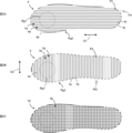
- 2A is a plan view schematically showing a linear structure 4 formed by scanning the linear resin 4b mainly in the first direction D1
- FIG. 2B is a plan view mainly showing the linear resin 5b mainly in the second direction D2.
- FIG. 2C is a plan view schematically showing a linear structure 5 formed by scanning the linear structure 5
- FIG. 2C is a plan view showing a shaped body 10 formed by alternately overlapping the linear structures 4 and the linear structures 5. It is a top view which shows typically. 2A to 2C are common to the embodiments of the first to fourth aspects.
- FIG. 1 is a perspective view schematically showing a structure 1 including a molded body 10 according to an embodiment of the first to fourth aspects.
- 2A is a plan view schematically showing a linear structure 4 formed by scanning the linear resin 4b mainly in the first direction D1
- FIG. 2B
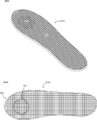
- FIG. 3A is a perspective view of the modeled body 10 having different linear resin thicknesses in the first elastic region Rg1 and the second elastic region Rg2, and FIG. 3B is a top view of the modeled body 10 shown in FIG. 3A.
- FIGS. 3A and 3B are common to the first and second embodiments.
- FIG. 4A is a perspective view schematically illustrating a three-dimensional modeling apparatus 50 for manufacturing the molded body 10 according to the embodiment
- FIG. 4B is a schematic view of a gear mechanism 11A1 provided inside the head 11 illustrated in FIG. 4A. It is. 4A and 4B are common to the first and second embodiments. It is a functional block diagram of control device Cnt which controls three-dimensional modeling device 50.
- FIG. 9 is a perspective view for explaining that the thickness of the linear resin discharged from the nozzle 12 is continuously changed when the linear structure 5 is formed.
- FIG. 3B is a top view of the shaped body 10B in which the arrangement interval of the linear resin is larger than the arrangement interval of the linear resin of the molded body 10 shown in FIGS. 3A and 3B. It is a functional block diagram of control device Cnt which controls three-dimensional modeling device 50. It is a perspective view of the modeled object 10 of the covering layer 3 of the structure 1 according to the embodiment.
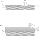
- FIG. 11A is an explanatory diagram of the impregnation layer forming step
- FIG. 11B is an explanatory diagram of the linear structure forming step. It is a perspective view of structure 1 of a 2nd embodiment of the 4th viewpoint of the present invention.
- the structure 1 includes a base material layer 2 and a coating layer 3.
- the structure 1 include those used in the field of nursing (pressure ulcer prevention supporter, foot foot prevention supporter, child cine, etc.), sports use (shoe insole, etc.).
- the structure 1 is provided with a coating layer 3 made of a soft material to enhance the feeling of use.
- the structure 1 is suitable for use in which the coating layer 3 is used in contact with a living body (eg, a human body).
- the structure 1 is an insole of a shoe.
- the base layer 2 is a layer on which the coating layer 3 is formed, and the base layer 2 and the coating layer 3 are in close contact with each other.
- the base layer 2 can be composed of, for example, a foam or a sponge.
- the resin material constituting the base layer 2 is not particularly limited. In the embodiment, an example in which the structure 1 includes the base material layer 2 and the coating layer 3 will be described as an example, but the embodiment is not limited thereto.
- the structure 1 does not have to include the base layer 2.
- the coating layer 3 covers at least a part of the base material layer 2.
- the coating layer 3 is formed of a resin material different from the resin material forming the base layer 2.
- the coating layer 3 is made up of the molded body 10.
- the coating layer 3 is configured from the modeled body 10, and the coating layer 3 does not have a configuration other than the modeled body 10, but the coating layer 3 has a configuration other than the modeled body 10. Is also good.
- the molded body 10 is configured by laminating two types of linear structures (linear structures 4 and 5 described later).
- Linear structures 4, 5 As shown in FIGS. 2A and 2B, the linear structures 4 and 5 are formed of one linear resin 4b and 5b. As shown in FIG. 2A, the linear resin 4b constituting the linear structure 4 extends in the first direction D1, and the linear resin 5b constituting the linear structure 5 extends in the second direction D1 as shown in FIG. 2B. Extends to D2. In the present embodiment, the first direction D1 and the second direction D2 are orthogonal, but the first direction D1 and the second direction D2 do not have to be orthogonal. Further, a plurality of grooves 4a, 5a are formed in the linear structures 4, 5. The groove 4a extends in the first direction D1, and the groove 5a extends parallel to the second direction D2. That is, a pair of adjacent linear portions 4c of the linear resin 4b is spaced, and similarly, a pair of adjacent linear portions 5c of the linear resin 5b is spaced.
- the molded body 10 is a structure having a plurality of linear structures 4 and a plurality of linear structures 5, and the linear structures 4 and the linear structures 5 are alternately stacked. For this reason, as shown in FIGS. 3A and 3B, the modeled body 10 is formed in a mesh shape, and the modeled body 10 has a large number of holes 3a. As a result, the air permeability of the structure 1 is improved, and the elasticity of the coating layer 3 of the structure 1 is improved.
- First and second elastic regions Rg1, Rg2 As shown in FIGS. 3A and 3B, the modeled object 10 has first and second elastic regions Rg1 and Rg2.
- the linear resin forming the first elastic region Rg1 is configured to be thinner than the linear resin forming the second elastic region Rg2.
- the linear structure 4 has first and second elastic regions Rg1 and Rg2, and the linear structure 5 also has first and second elastic regions Rg1 and Rg2.
- the outer edge of the first elastic region Rg1 of the linear structure 4 and the outer edge of the first elastic region Rg1 of the linear structure 5 match.
- the first elastic region Rg1 of the linear structure 4 and the first elastic region Rg1 of the linear structure 5 overlap.
- the edges (outer and inner edges) of the second elastic regions Rg2 of the linear structures 4 and the edges (the outer edges and the inner edges) of the second elastic regions Rg2 of the linear structures 5 overlap so that the outer edge and the inner edge coincide.
- first and second elastic regions Rg1 and Rg2 of the linear structure 4 and the first and second elastic regions Rg1 and Rg2 of the linear structure 5 are overlapped with each other.
- the first and second elastic regions Rg1 and Rg2 extend from the lowermost layer to the uppermost layer of the linear structures 4 and 5.
- the first elastic region Rg1 is disposed inside the second elastic region Rg2. Further, the first elastic region Rg1 and the second elastic region Rg2 are connected so as to be continuous. That is, no intervening region exists between the first elastic region Rg1 and the second elastic region Rg2.
- the three-dimensional printing apparatus 50 includes a head 11, a nozzle 12, a frame 20, a pair of first guide units 21, a second guide unit 22, a table driving unit 30, and a forming table 31. .
- a wire 14 made of resin is inserted into the head 11.
- the three-dimensional printing apparatus 50 includes a first driving unit that moves the head 11 along the second guide unit 22 and a second driving unit that moves the second guide unit 22 to a pair of second guide units 22. And a second drive unit that moves along the direction.
- the first drive unit and the second drive unit correspond to the head drive unit 15 shown in FIG.
- the three-dimensional printing apparatus 50 includes a control device Cnt for controlling various actuators.
- the head 11 is provided on the second guide portion 22, and the head 11 is configured to be movable in the first direction D1.
- a resin supply mechanism 11A and a heater 11B are provided in the head 11.
- the resin supply mechanism 11A is a mechanism for sending out the wire rod 14 inserted into the head 11 to the nozzle 12, and the resin supply mechanism 11A includes a gear mechanism 11A1 (see FIG. 4B) and a motor (not shown) for rotating the gear mechanism. can do.
- the wire 14 is engaged with a gear mechanism of the resin supply mechanism 11 ⁇ / b> A, and the wire mechanism is rotated to send the wire 14 to the nozzle 12.
- the heater 11B is disposed above the nozzle 12.
- the wire 14 is softened, and the softened wire 14 is discharged from the nozzle 12 as a linear resin.
- the mode in which the wire rod 14 is sent out to the nozzle 12 by the gear mechanism 11A1 has been described, but the present invention is not limited to this mode.
- the three-dimensional modeling device 50 may be configured to supply the pellet type resin to the nozzle 12.
- the three-dimensional modeling device 50 may be configured to supply the pellet-shaped resin to the nozzle 12 instead of the gear mechanism 11A1.
- a motor provided to rotate the screw.
- Nozzle 12 is fixed to the lower part of head 11. As the head 11 moves with respect to the second guide portion 22 and the second guide portion 22 moves with respect to the pair of first guide portions 21, the nozzles 12 two-dimensionally scan the modeling table 31.
- the frame 20 supports the pair of first guide portions 21 and second guide portions 22.
- a modeling table 31 is arranged inside the frame 20.
- the table drive unit 30 has a function of moving the modeling table 31 up and down. Each time a linear structure of an arbitrary layer is formed, the table driving unit 30 moves the modeling table 31 downward, so that the three-dimensional modeling apparatus 50 can stack the linear structures.
- the control device Cnt of the three-dimensional printing apparatus 50 acquires target object data relating to an object (in the present embodiment, a human foot) using the structure 1.
- the acquired object data is, for example, pressure distribution data or external shape data.
- the pressure distribution data is data indicating the load applied to the object
- the outer shape data is data indicating the surface shape of the object.
- the control device Cnt includes a calculation unit U1, an operation control unit U2, and a storage unit U3.
- the calculation unit U1 generates molding data for molding the molded body 10 based on the acquired target object data.
- This modeling data includes scanning path data and thickness data.
- the operation control unit U2 controls the head driving unit 15, the table driving unit 30, the resin supply mechanism 11A, and the heater 11B.
- the storage unit U3 stores various data such as modeling data.
- Each functional unit included in the control device Cnt is configured by dedicated hardware or an MPU (Micro Processing Unit) that executes a program stored in the storage unit U3.
- the control device Cnt is dedicated hardware, the control device Cnt is, for example, a single circuit, a composite circuit, an ASIC (application specific integrated circuit), an FPGA (field-programmable gate array), or a combination thereof. Applicable.
- Each of the function units realized by the control device Cnt may be realized by individual hardware, or each function unit may be realized by one piece of hardware.
- each function executed by the control device Cnt is realized by software, firmware, or a combination of software and firmware. Software and firmware are described as programs and stored in the storage unit U3.
- the MPU realizes each function of the control device Cnt by reading and executing the program stored in the storage unit U3.
- the storage unit U3 is, for example, a nonvolatile or volatile semiconductor memory such as a RAM, a ROM, a flash memory, an EPROM, and an EEPROM.
- the scan path data is data that determines the path of the nozzle 12 when the nozzle 12 is two-dimensionally scanned.
- the scanning path data defines, for example, the scanning pitch of the nozzles 12 when the nozzles 12 are two-dimensionally scanned and the coordinates of the nozzles 12 when the nozzles 12 are two-dimensionally scanned.
- the scanning pitch defined by the scanning path data corresponds to the pitch Pt1
- the scanning pitch defined by the scanning path data corresponds to the pitch Pt2.
- the coordinates defined by the scanning path data are, for example, coordinates such as the coordinates P1 of the outer edge of the second elastic region Rg2.
- the coordinates defined by the path data are, for example, coordinates such as the coordinates P2 of the outer edge of the second elastic region Rg2. Further, the coordinates defined by the scan path data include the coordinates defining the boundary between the first elastic region Rg1 and the second elastic region Rg2.
- the scanning path data is described as being changed based on the target object data, but is not limited thereto. Even if the object data is different, the same scan path data may be used.
- the thickness data is associated with the scan path data, and the thickness data is data for determining the thickness of the linear resin discharged from the nozzles 12.
- the thickness of the linear resin discharged from the nozzle 12 can be changed by changing the amount of the wire 14 (the length of the wire 14) sent out from the resin supply mechanism 11A to the nozzle 12 per unit time. That is, when the operation control unit U2 controls the resin supply mechanism 11A, the thickness of the linear resin discharged from the nozzle 12 changes.
- the thickness data corresponds to the control data of the resin supply mechanism 11A.
- the means for changing the thickness of the linear resin discharged from the nozzle 12 is not limited to this.
- the nozzle 12 may be configured such that the opening diameter for discharging the linear resin is variable. That is, the nozzle 12 is provided with a diameter changing mechanism that changes the opening diameter of the nozzle 12, and the operation control unit U2 controls the diameter changing mechanism based on the modeling data.
- the thickness data of the molding data corresponds to the control data of the diameter changing mechanism.
- the linear resin becomes thicker as the opening diameter of the nozzle 12 increases. Further, the thickness of the linear resin discharged from the nozzle 12 can be changed by, for example, changing the scanning speed of the nozzle 12.
- the thickness of the linear resin discharged from the nozzle 12 can be changed by changing the distance that the nozzle 12 scans per unit time.
- the thickness data corresponds to the control data of the head driving unit 15. Note that, as the scanning speed of the nozzle 12 becomes slower, the amount of the linear resin discharged from the nozzle 12 to an arbitrary position also increases. Therefore, as the scanning speed of the nozzle 12 becomes slower, the linear resin becomes thicker.
- the method for manufacturing the structure 1 according to the embodiment includes an acquisition step, a generation step, and a modeling step.
- the control device Cnt acquires target object data from, for example, a measuring device.
- the measuring device corresponds to a device for measuring the pressure distribution of the foot or a device for scanning the outer shape of the foot.
- the calculation unit U1 of the control device Cnt generates the modeling data of the modeling body 10 based on the target object data.
- the generated modeling data includes the scanning path data and the thickness data as described above.
- the scanning path data defines the range of the first and second elastic regions Rg1 and Rg2 in addition to defining the path for scanning the nozzle 12.
- the thickness data associated with the scan path data includes the control data of the resin supply mechanism 11A in the first elastic region Rg1 (the delivery amount of the wire 14) and the control data of the resin supply mechanism 11A in the second elastic region Rg2 (the control data of the resin supply mechanism 11A). (The delivery amount of the wire 14).
- the sending amount of the wire 14 refers to the amount of the wire 14 that the resin supply mechanism 11A sends out to the nozzle 12 per unit time.
- the operation control unit U2 of the control device Cnt controls the head driving unit 15, the table driving unit 30, and the resin supply mechanism 11A based on the modeling data.
- the base material layer 2 that has been manufactured in advance is placed on the modeling table 31.
- the base material layer 2 can also be formed in a forming step.
- the linear resin constituting the linear structures 4 and 5 is composed of one linear resin. That is, when the nozzle 12 performs two-dimensional scanning, the path of the nozzle 12 is drawn with one stroke.
- the shapes of the linear resins 4b and 5b shown in FIGS. 2A and 2B correspond to the paths of the nozzles 12 when the linear structures 4 and 5 are formed in the forming step.
- each component operates as follows. That is, as shown in FIG. 6, when the nozzle 12 passes through a portion of the path of the nozzle 12 that belongs to the second elastic region Rg2, the resin supply mechanism 11A operates so as to increase the amount of wire 14 to be delivered. . Further, when the nozzle 12 passes through a portion belonging to the first elastic region Rg1 in the path of the nozzle 12, the resin supply mechanism 11A operates so as to reduce the amount of wire 14 to be delivered. As a result, the linear resin forming the first elastic region Rg1 becomes thinner than the linear resin forming the second elastic region Rg2.
- the operation control unit U2 controls the table driving unit 30 to form the object.
- the table 31 is moved downward.
- the operation control unit U2 causes the nozzle 12 to scan a path corresponding to the other shape of the linear resin 4b and the linear resin 5b, and the operation control unit U2 controls the table driving unit 30 to form the object.
- the table 31 is moved downward.
- the molded body 10 has first and second elastic regions Rg1 and Rg2, and the linear resin forming the first elastic region Rg1 is thinner than the linear resin forming the second elastic region Rg2. I have. That is, the modeled body 10 has different elasticity (cushioning property) depending on the location, and as a result, the modeled body 10 has a configuration that can enhance the user's feeling of use. Specifically, the first elastic region Rg1 is softer than the second elastic region Rg2 and has more cushioning properties than the second elastic region Rg2. The portion of the elastic region Rg1 is gently received.
- the formation positions of the first and second elastic regions Rg1 and Rg2 shown in FIG. 2A and the like are only examples, and are not limited to the formation positions.
- the scanning pitch when the nozzle 12 is two-dimensionally scanned is the same for the first elastic region Rg1 and the second elastic region Rg2.
- the scanning pitch when the nozzle 12 is two-dimensionally scanned is the pitch Pt1 shown in FIG. 2A in all regions, that is, is constant.
- the scanning pitch when the nozzle 12 is two-dimensionally scanned is the pitch Pt2 shown in FIG. 2B in all regions, that is, is constant.
- the modeling body 10 employs a configuration in which the elasticity (cushioning property) differs depending on the location, the three-dimensional modeling apparatus 50 maintains the scanning pitch when the nozzle 12 is two-dimensionally scanned while keeping the scanning pitch constant.
- the molded object 10 can be formed. For this reason, even if the modeling object 10 employs a configuration having different elasticity (cushioning property) depending on the location, the complexity of the two-dimensional scanning path of the nozzle 12 is suppressed. Therefore, in the case of manufacturing a modeled body having different elasticity (cushioning property) depending on the location, the two-dimensional scanning path is complicated, so that the three-dimensional modeling apparatus cannot model the model or the configuration of the modeled body needs to be changed. Can be avoided.
- the thickness of the linear resin discharged from the nozzle 12 can be changed.
- the manufacturing method of the modeled object 10 according to the embodiment can model a modeled object whose elasticity (cushioning property) changes continuously and smoothly.
- the method for manufacturing the molded body 10 according to the embodiment has advantageous effects. As shown in FIG.
- the linear resin discharged from the nozzle 12 is thinned, and when the nozzle 12 scans the end 5d, the linear resin is discharged from the nozzle 12. Increase the thickness of the linear resin.
- the linear resin discharged from the nozzle 12 is gradually thickened or gradually reduced. Make it thin.
- the outer peripheral portion of the linear structure 5 (corresponding to the outer peripheral portion of the molded body 10) is configured to be hard, and the inner portion of the outer peripheral portion of the linear structure 5 is softened. Can be configured.
- the molded body in the filling rate control method, can be hardened by reducing the arrangement interval of a pair of adjacent linear resins, that is, by increasing the filling rate.
- the arrangement interval between a pair of adjacent linear resins is reduced, the scanning pitch of the nozzles 12 is shortened accordingly, and the scanning time of the nozzles 12 is increased, and as a result, the molding time of the molded body 10 is increased.
- the elasticity cushioning property
- the elasticity can be varied according to each position of the modeled body 10 by changing the thickness of the linear resin discharged from the nozzle 12.
- the molded body 10 can be hardened by increasing the thickness of the linear resin without reducing the arrangement interval of the linear resin. That is, the method of manufacturing the modeled body 10 according to the embodiment can suppress an increase in the modeling time of the modeled body 10 when the modeled body 10 is hardened.
- the method of manufacturing the modeled object 10 according to the embodiment has an advantageous effect. That is, in the manufacturing method of the modeled body 10 according to the embodiment, by changing the thickness of the linear resin discharged from the nozzle 12, the elasticity (cushioning property) can be varied depending on each position of the modeled body 10. Therefore, in the manufacturing method, it is possible to suppress variations of the scan path data stored in the control device Cnt, and to suppress a load when the control device Cnt calculates the scan path data. As described above, the manufacturing method according to the embodiment can reduce the complexity of the processing performed by the control device Cnt when forming the molded body 10, and as a result, the manufacturing method according to the embodiment includes the structure 1 Easy to automate the manufacturing process.
- the elasticity of the first elastic region Rg1 and the elasticity of the second elastic region Rg2 are determined. Although it can be different, it is difficult to compose the path of the nozzle 12 with one stroke. In particular, when the first elastic region Rg1 is arranged inside the second elastic region Rg2 as in the modeled object 10 according to the embodiment, it is more difficult to configure the path of the nozzle 12 with one stroke. Prone.
- the first elastic region Rg1 and the second elastic region Rg2 are separately set. Need to be shaped. If the first elastic region Rg1 and the second elastic region Rg2 are separately formed, the first elastic region Rg1 and the second elastic region Rg2 become discontinuous, so that the first elastic region Rg1 deviates from the second elastic region Rg2. As a result, the feeling of use of the molded body (insole) is deteriorated, which leads to a decrease in the quality of the molded body.
- the molding time of the molded body becomes longer.
- the first elastic region Rg1 and the second elastic region Rg2 are connected so as to be continuous. For this reason, in the molded object 10 according to the embodiment, the deterioration of the quality is suppressed, and the prolongation of the molding time is suppressed.
- Base material layer 2 The description of the base material layer 2 according to the embodiment of the second aspect is given in 1-1. The description is omitted because it is the same as the base material layer 2.
- Coating layer 3 The description of the coating layer 3 of the embodiment of the second aspect is given in 1-2. The description is omitted because it is the same as the coating layer.
- Modeling object 10B The shape of the model of the covering layer 3 is not limited to the model 10 described above.
- the shaped body of the coating layer 3 may be a shaped body 10B shown in FIG.
- the arrangement interval of the linear resin in the first elastic region Rg1 of the modeled object 10B is wider than the arrangement interval of the linear resin in the first elastic region Rg1 of the modeled object 10B. That is, the filling rate of the first elastic region Rg1 of the modeled body 10B is smaller than the filling rate of the first elastic region Rg1 of the modeled body 10.
- the first elastic region Rg1 of the modeled body 10B also has a cushioning-rich configuration, similarly to the first elastic region Rg1 of the modeled body 10.
- the hardness of the shaped body can be changed by changing the thickness of the linear resin as in the shaped body 10, but the filling rate of the linear resin can be changed as in the shaped body 10B, and the hardness of the shaped body can be changed. Can be changed.
- the three-dimensional modeling apparatus 50 is used in the method of manufacturing the structure 1.
- the system for manufacturing the structure 1 includes an acquisition unit, a generation unit, and a modeling unit.
- the three-dimensional printing apparatus 50 corresponds to a printing unit in a system for manufacturing the structure 1.
- the three-dimensional printing apparatus 50 includes a head 11, a nozzle 12, a frame 20, a pair of first guide units 21, a second guide unit 22, a table driving unit 30, and a forming table 31. .
- a wire 14 made of resin is inserted into the head 11.
- the three-dimensional printing apparatus 50 includes a first driving unit that moves the head 11 along the second guide unit 22 and a second driving unit that moves the second guide unit 22 to a pair of second guide units 22. And a second drive unit that moves along the direction.
- the first drive unit and the second drive unit correspond to the head drive unit 15 shown in FIG.
- the three-dimensional printing apparatus 50 includes a control device Cnt for controlling various actuators.
- the control device Cnt of the three-dimensional printing apparatus 50 acquires target object data relating to an object (in the present embodiment, a human foot) using the structure 1.
- the acquired object data is pressure distribution data and outer shape data.
- the pressure distribution data is data indicating the load applied to the object
- the outer shape data is data indicating the surface shape of the object.
- the control device Cnt acquires pressure distribution data from the pressure measurement unit Se1.
- the control device Cnt acquires the outline data from the outline scanning unit Se2.
- the three-dimensional modeling device 50 corresponds to an acquisition unit in a system that manufactures the structure 1, the pressure measurement unit Se1 and the outer shape scanning unit Se2.
- the control device Cnt includes a calculation unit U1, an operation control unit U2, and a storage unit U3.
- the operation unit U1 of the control device Cnt corresponds to a generation unit in a system that manufactures the structure 1.
- the calculation unit U1 generates molding data for molding the molded body 10 based on the acquired target object data.
- This modeling data includes scanning path data and thickness data.
- the operation control unit U2 controls the head driving unit 15, the table driving unit 30, the resin supply mechanism 11A, and the heater 11B.
- the storage unit U3 stores various data such as modeling data.
- each functional unit, scan path data, and thickness data included in the control device Cnt are described in 2-2. Since the content is the same as that described in the functional block of the control device Cnt, the description is omitted. Further, also in the embodiment of the second aspect, as means for changing the thickness of the linear resin discharged from the nozzle 12, 2-2. The contents described in the functional blocks of the control device Cnt can be adopted.
- the method for manufacturing the structure 1 according to the embodiment includes an acquisition step, a generation step, and a modeling step.
- the control device Cnt acquires the pressure distribution data from the pressure measurement unit Se1, and acquires the outer shape data from the outer shape scan unit Se2.
- the control device Cnt acquires the contour data in addition to the pressure distribution data.
- the control device Cnt may not acquire the contour data.
- the calculation unit U1 of the control device Cnt generates modeling data of the modeling bodies 10 and 10B based on the target object data.
- the generated modeling data includes the scanning path data and the thickness data as described above.
- the calculation unit U1 generates modeling data of the modeling bodies 10, 10B based on the pressure distribution data and the outer shape data.
- the control device Cnt stores a program that can determine an insole shape suitable for the user's foot based on the pressure distribution of the target and the outer shape of the target.
- the calculation unit U1 generates modeling data of the modeling bodies 10 and 10B based on the algorithm of the program.
- the algorithm of this program can set an area in the pressure distribution data where the pressure is higher than a predetermined pressure value as the first elastic area Rg1. Also, the algorithm of this program is that if the variation of the pressure value of the pressure distribution data is smaller than a predetermined value and the average of the pressure values of the pressure distribution data is lower than the predetermined pressure value, The filling rate of the resin may be set constant, and the filling rate of the linear resin may be set low. As described above, the algorithm of the program can be determined based on the properties of the target object, the demands of the user, and the like.
- the scanning path data defines a path for scanning the nozzle 12.
- the scan path data defines the range of the first and second elastic regions Rg1 and Rg2.
- the thickness data associated with the scan path data includes the control data of the resin supply mechanism 11A in the first elastic region Rg1 (the delivery amount of the wire 14) and the control data of the resin supply mechanism 11A in the second elastic region Rg2 (the control data of the resin supply mechanism 11A). (The delivery amount of the wire 14).
- the sending amount of the wire 14 refers to the amount of the wire 14 that the resin supply mechanism 11A sends out to the nozzle 12 per unit time.
- the operation control unit U2 of the control device Cnt controls the head driving unit 15, the table driving unit 30, and the resin supply mechanism 11A based on the modeling data.
- the base material layer 2 that has been manufactured in advance is placed on the modeling table 31.
- the base material layer 2 can also be formed in a forming step.
- the structure 1 is modeled based on the modeling data generated in the generation step so that the flexibility (cushioning property) of the structure 1 changes.
- the flexibility (cushioning property) of the structure 1 can be changed by adjusting the thickness of the linear resin (see FIG. 3B) or adjusting the pitch of the linear resin (see FIG. 8).
- the configuration of FIG. 3B and the configuration of FIG. 8 are independent, the structure 1 according to the embodiment has the configuration of the first elastic region Rg1 of FIG. 3B and the configuration of the first elastic region Rg1 of FIG. Both may be provided.
- the linear resin constituting the linear structures 4 and 5 of the molded body 10 is formed of one linear resin. That is, when the nozzle 12 performs two-dimensional scanning, the path of the nozzle 12 is drawn with one stroke.
- the shapes of the linear resins 4b and 5b shown in FIGS. 2A and 2B correspond to the paths of the nozzles 12 when the linear structures 4 and 5 are formed in the forming step.
- each component operates as follows. That is, when the nozzle 12 passes through a portion of the path of the nozzle 12 that belongs to the second elastic region Rg2, the resin supply mechanism 11A operates so as to increase the amount of wire 14 to be delivered. Further, when the nozzle 12 passes through a portion belonging to the first elastic region Rg1 in the path of the nozzle 12, the resin supply mechanism 11A operates so as to reduce the amount of wire 14 to be delivered. As a result, the linear resin forming the first elastic region Rg1 becomes thinner than the linear resin forming the second elastic region Rg2.
- the first elastic region Rg1 of the modeled body 10B is different from the first elastic region Rg1 of the modeled body 10, and a part of the linear resin of the first elastic region Rg1 of the modeled body 10B is interrupted. It is preferable that the nozzle 12 does not discharge the linear resin when the nozzle 12 scans the interrupted portion. Further, the scanning path of the nozzle 12 may be set so as to bypass the interrupted portion so that the nozzle 12 does not scan the interrupted portion.
- the operation control unit U2 controls the table driving unit 30 to form the object.
- the table 31 is moved downward.
- the operation control unit U2 causes the nozzle 12 to scan a path corresponding to the other shape of the linear resin 4b and the linear resin 5b, and the operation control unit U2 controls the table driving unit 30 to form the object.
- the table 31 is moved downward.
- the manufacturing method according to the embodiment and the system according to the embodiment form a structure based on the forming data generated based on the pressure distribution data. That is, in the manufacturing method according to the embodiment and the system according to the embodiment, since the structure is formed in consideration of the pressure distribution indicating the load applied to the object to be formed, the usability of the structure can be enhanced.
- the scanning path data or the thickness data is changed according to the pressure distribution data.
- the generation unit (the operation unit U1) changes the scanning path data or the thickness data according to the pressure distribution data.
- the scan path data the filling rate of the linear resin can be changed, and the elasticity (cushioning property) of the modeled object can be changed.
- the thickness data the elasticity (cushioning property) of the modeled object can be changed.
- the manufacturing method according to the embodiment and the system according to the embodiment use a plurality of methods, that is, a method of changing the filling rate and a method of changing the thickness of the linear resin, to elasticity (cushioning property) of the molded body. Can be changed, it is possible to form the structure 1 according to the properties of the object and the user's request, and as a result, the manufacturing method according to the embodiment and the system according to the embodiment use the structure 1 The feeling can be enhanced.
- the manufacturing method and the system according to the embodiment change the thickness of the linear resin according to the location of the shaped body (see FIGS. 3A and 3B), and the filling rate of the linear resin according to the location of the shaped body. Can be changed (see FIG. 8), and in the manufacturing method and the system according to the embodiment, it is possible to form a shaped body having a different elasticity (cushioning property) depending on a portion like the shaped body 10. For this reason, the manufacturing method and system according to the embodiment can further enhance the usability of the structure 1.
- the molding data is generated based on the pressure distribution data and the outer shape data.
- the generation unit (the operation unit U1) generates the molding data based on the pressure distribution data and the outer shape data. That is, the control device Cnt generates modeling data in consideration of not only the pressure distribution of the object but also the outer shape of the object. For this reason, in the manufacturing method and system according to the embodiment, it is possible to form a shaped body having a shape suitable for an object and a hardness suitable for the object, and as a result, the manufacturing method and the system according to the embodiment In the system, the usability of the structure 1 can be further enhanced.
- the base layer 2 is a layer on which the coating layer 3 is formed, and the base layer 2 and the coating layer 3 are in close contact with each other.
- the base layer 2 is formed of a foam, and the foam of the base layer 2 is formed with bubbles into which the resin constituting the coating layer 3 enters.
- the base material layer 2 can be composed of a foam having a large number of cells, and can also be composed of a sponge having a large number of cells.
- the resin material constituting the base layer 2 is not particularly limited.
- the cell structure of the base layer 2 may be an open cell structure or a closed cell structure. In the open-cell structure, the resin is more likely to enter deeper than in the closed-cell structure, and the strength of the closed-cell structure is higher than in the open-cell structure.
- the coating layer 3 covers at least a part of the base material layer 2.
- the coating layer 3 is formed of a resin material different from the resin material forming the base layer 2.
- the coating layer 3 has a modeled body 10 and an impregnated layer 6. As shown in FIGS. 2A to 2C, the modeled body 10 is configured by stacking two types of linear structures (linear structures 4 and 5).
- Linear structures 4, 5 In the embodiment of the third aspect, the description of the linear structures 4 and 5 is described in 1-2-1 of the embodiment of the first aspect. The description is omitted because it is the same as the linear structures 4 and 5.
- Impregnation layer 6 The resin constituting the impregnation layer 6 is impregnated in the base material layer 2. Specifically, in the present embodiment, since the base material layer 2 is a foam, the resin constituting the impregnation layer 6 is contained in the cells of the foam of the base material layer 2. As described above, by impregnating the resin constituting the impregnation layer 6 into the base material layer 2, the resin constituting the impregnation layer 6 becomes entangled with the foam constituting the base material layer 2, and as a result, the impregnation layer 6 It is firmly bonded to the base material layer 2.
- the resin material forming the impregnated layer 6 is the same as the resin material forming the shaped body 10.
- the impregnated layer 6 and the molded body 10 are firmly bonded.
- the coating layer 3 is prevented from peeling off from the base layer 2.
- the position of the surface of the impregnation layer 6 substantially coincides with the surface of the base material layer 2, but the surface of the impregnation layer 6 may protrude from the surface of the base material layer 2.
- the method of manufacturing the structure 1 according to the embodiment includes an impregnation layer forming step and a linear structure forming step.
- the three-dimensional modeling apparatus of the method of manufacturing the structure 1 according to the embodiment includes a nozzle 12, a heating unit (not shown), and a resin supply unit (not shown).
- the nozzle 12 has a function of linearizing the resin supplied from the resin supply unit.
- the heating means is attached to, for example, the nozzle 12, and the resin supplied to the nozzle 12 is softened by the heat of the heating means.
- the linear resin Rs is discharged from the nozzle 12 into the base layer 2 while the nozzle 12 for discharging the linear resin Rs is pushed into the base layer 2.
- the linear resin Rs corresponds to the linear resin 4b or the linear resin 5b shown in FIGS. 2A to 2C.
- the linear resin Rs discharged from the nozzle 12 enters the bubbles of the base layer 2, so that the linear resin Rs is entangled with the foam constituting the base layer 2. That is, the impregnation layer 6 and the base material layer 2 have an anchor effect. As described above, in the embodiment, the impregnated layer 6 is firmly bonded to the base layer 2 by the anchor effect, and the adhesion between the impregnated layer 6 and the base layer 2 is improved.
- the nozzle 12 is two-dimensionally scanned. Specifically, the two-dimensional scanning range of the nozzle 12 in the impregnation layer forming step is determined according to the shape of the lowermost linear structure Bd of the modeled object 10.
- the linear structure Bd corresponds to the linear structure 4 or the linear structure 5 shown in FIGS. 2A to 2C.
- the linear structure Bd in the lowermost layer of the modeling body 10 is the linear structure 4
- the linear structure Bd in the layer immediately above the linear structure Bd in the lowermost layer is a linear structure.
- Body 5 is the linear structure Bd in the layer immediately above the linear structure Bd in the lowermost layer.
- the two-dimensional scanning range of the nozzle 12 in the impregnation layer forming step (hereinafter, referred to as a first range) is the two-dimensional scanning range of the nozzle 12 in the lowermost linear structure Bd of the modeled object 10. (Hereinafter, referred to as a second range) or is preferably wider than the second range so as to include the entire second range. Thereby, the entire lower part of the modeled body 10 is formed on the impregnated layer 6, and peeling of the modeled body 10 from the base layer 2 is more reliably suppressed.
- the second range may protrude from the first range.
- the adhesion between the coating layer 3 and the base material layer 2 is reduced as compared with the portion that does not protrude.
- the adhesion between the coating layer 3 and the base material layer 2 is high in the portions that do not protrude, the effect of suppressing the coating layer 3 from being peeled off from the base material layer 2 is obtained.
- the trajectory of the tip of the nozzle 12 when forming the impregnation layer 6 may be similar to the trajectory of the tip of the nozzle 12 when forming the lowermost linear structure Bd of the modeled object 10.
- the first area of the base layer 2 is not completely covered with the impregnated layer 6, and the ventilation between the holes 3 a of the cover layer 3 and the bubbles of the base layer 2 is blocked by the impregnated layer 6.
- the air permeability of the structure 1 is improved.
- the pressing amount Dp which is the amount of pressing the nozzle 12 into the base material layer 2
- the thickness of the linear resin Rs is the same as the lamination pitch of the linear structure Bd.
- the linear resin Rs discharged from the nozzle 12 not only easily enters the base material layer 2, but also the linear resin Rs discharged from the nozzle 12 enters deeper into the base material layer 2. Therefore, the anchor effect is enhanced, and the impregnated layer 6 is more strongly bonded to the base material layer 2.
- the resin that has entered the base material layer 2 may sometimes spread too much laterally.
- the resin of the adjacent two-dimensional scan path comes into contact. Sometimes. When the resins of the adjacent two-dimensional scanning paths come into contact with each other, the first area of the base material layer 2 is covered with the impregnated layer 6, and the air permeability of the structure 1 is reduced.
- each linear resin Rs constituting each linear structure Bd is composed of one linear resin.
- the trajectory of the tip of the nozzle 12 when the nozzle 12 performs two-dimensional scanning is drawn in a single stroke.
- the linear resin is discharged from the nozzle to the base material layer with the nozzle spaced from the base material layer. Therefore, in the conventional manufacturing method, the resin discharged from the nozzle hardly impregnates the base material layer, and the anchor effect cannot be obtained.
- the structure 1 according to the embodiment when the nozzle 12 is pushed into the base layer 2, the linear resin Rs discharged from the nozzle 12 enters the bubbles of the base layer 2 and solidifies. .
- the resin that has become the impregnated layer 6 by solidification is entangled with the foam constituting the base layer 2, and the impregnated layer 6 and the base layer 2 have an anchor effect. Due to this anchor effect, the impregnated layer 6 is firmly bonded to the base material layer 2, and the adhesion between the impregnated layer 6 and the base material layer 2 is improved.
- a manufacturing method using a three-dimensional modeling apparatus is different from a manufacturing method using a mold (for example, a manufacturing method using injection molding).
- the time required to complete one structure increases. Therefore, it is conceivable to prepare the base layer 2 by injection molding in advance, and to form the molded body 10 on the base layer 2 with a three-dimensional forming apparatus.
- the resin material forming the base layer 2 and the resin material forming the molded body 10 are the same, the base layer 2 and the molded body 10 are easily brought into close contact by the means.
- the resin material forming the base layer 2 may be different from the resin material forming the molded body 10.
- the manufacturing method according to the embodiment to the base material layer 2 manufactured by injection molding in advance. Thereby, even if the resin material forming the base material layer 2 and the resin material forming the molded body 10 are different, it is possible to efficiently manufacture structures having various shapes which are difficult to manufacture by injection molding or the like. it can.
- the base material layer 2 is a layer formed of a shape memory material including a shape memory polymer.
- the shape memory material is a material having shape memory characteristics, and has a characteristic of being restored to an original shape by elasticity when heated to a predetermined recovery temperature or higher.
- the shape memory material preferably includes only the shape memory polymer, but may include another component as long as the shape memory characteristics are not impaired.
- Components other than the shape memory polymer include resins such as polyolefins such as polyethylene and polypropylene, and fillers.
- the proportion of the shape memory polymer in the shape memory material is, for example, 50 to 100% by mass, and specifically, for example, 50, 55, 60, 65, 70, 75, 80, 85, 90, 95, 100% by mass. And may be in a range between any two of the numerical values exemplified here.
- the recovery temperature of the shape memory material usually matches the glass transition temperature of the shape memory polymer.
- Shape memory polymer has the property of returning to its original shape by elasticity when heated to a temperature exceeding Tg.
- Tg is, for example, 35 to 100 ° C., preferably 40 to 75 ° C., and specifically, for example, 35, 40, 45, 50, 55, 60, 65, 70, 75, 80, 85, 90 , 95, and 100 ° C., and may be in a range between any two of the numerical values exemplified here.
- a secondary shape When a secondary shape is formed by applying an external force at a temperature exceeding Tg, and cooling to a temperature below Tg while maintaining the external force, the secondary shape is fixed. At a temperature lower than Tg, the material does not return to its original shape even when the external force is removed.
- the shape memory polymer provided with the secondary shape is heated to a temperature exceeding Tg so that no external force is applied, the shape memory polymer returns to the original shape by elasticity.
- the original shape can be set, for example, by melting a shape memory polymer and molding it into a desired shape.
- the shape memory polymer include polymers having rubber elasticity, such as polynorbornene, trans polyisoprene, styrene-butadiene copolymer, and polyurethane.
- Shape memory polymers and shape memory materials containing the same have the property that the elastic modulus changes significantly near Tg.
- the value of the elastic modulus at (Tg ⁇ 20 ° C.) / The elastic modulus at (Tg + 20 ° C.) is 10 or more.
- the structure 1 is deformed at a temperature equal to or higher than (Tg + 20 ° C.)
- the structure 1 can be used at a temperature of 20 ° C. or lower. For this reason, the shape of the structure can be easily changed to a shape set for each user, and the shape can be maintained during use.
- the value of the elastic modulus at (Tg ⁇ 20 ° C.) / The elastic modulus at (Tg + 20 ° C.) is, for example, 10 to 1000, and specifically, for example, 10, 20, 30, 40, 50, 60, 70, 80, 90, 100, 200, 300, 400, 500, 1000 and may be in the range between any two of the numerical values exemplified here.
- the slope of the graph at Tg is, for example, ⁇ 1 to ⁇ 0. 025, preferably -0.5 to -0.1.
- the value of this slope is, for example, -1, -0.9, -0.8, -0.7, -0.6, -0.5, -0.4, -0.3, -0.2, -0.1, -0.075, -0.050, -0.025, and may be in the range between any two of the numerical values exemplified here.
- a slope of -1 in the graph means that the elastic modulus becomes 10 times when the temperature decreases by 1 ° C
- a slope of -0.025 in the graph means that the elastic modulus increases by a temperature decrease of 40 ° C. Means 10 times.
- X is preferably 20 or less, for example, 0.5 to 20, and specifically, for example, 0.5, 1, 2, 3, 4, 5, 6, 7, 8, 9, 10, 11, 12, 13, 14, 15, 16, 17, 18, 19, 20 and are exemplified here. It may be in the range between any two of the numerical values.
- the elastic modulus means a storage elastic modulus determined by a dynamic viscoelasticity test, and can be measured according to JIS K7244.
- the base layer 2 is formed of a thermoplastic resin other than the shape memory material, it is possible to reduce the elastic modulus of the base layer as the temperature rises.
- a plastic resin since the decrease in the elastic modulus due to a rise in temperature is usually gradual, it is easy to perform an operation of raising the temperature of the base material layer 2 to deform it, and then lowering the temperature to maintain the deformed shape. Therefore, the base material layer 2 needs to be formed of a shape memory material.
- the coating layer 3 covers at least a part of the base material layer 2.
- the coating layer 3 is formed of a soft material.
- the soft material is a material that can be easily elastically deformed at room temperature, and an example is an elastomer having a Tg lower than room temperature. Examples of the elastomer include a styrene-based elastomer.
- the Tg of the soft material is preferably 20 ° C. or lower, more preferably 10 ° C. or lower, and further preferably 0 ° C. or lower.
- the soft material is preferably softer than the shape memory material at room temperature (25 ° C.), and preferably has a lower elastic modulus than the shape memory material at room temperature.
- the usability of the structure 1 is improved by covering the base layer 2 with a covering layer 3 formed of a soft material at a portion that comes into contact with the user.
- the method for manufacturing the structure 1 is not particularly limited, and can be formed by a method such as injection molding or 3D printer modeling.
- the base layer 2 and the coating layer 3 can be integrally formed by two-color molding using a shape memory material and a soft material.
- one of the base layer 2 and the coating layer 3 may be formed by injection molding, and the other may be formed thereon by 3D printer modeling.
- both the base layer 2 and the coating layer 3 may be formed by 3D printer modeling.
- the structure 1 can be formed so as to have a shape set for each user, it is preferable that at least one of the base layer 2 and the coating layer 3 is formed by 3D printer modeling.
- a linear resin formed by extruding a molten resin from a head is two-dimensionally scanned as shown in FIGS. 2A to 2B to form linear structures 4 and 5, and a linear structure is formed.
- a molded object can be formed by laminating 4 and 5.
- the resin may be supplied to the head in the form of a filament or in the form of a pellet. In the latter case, a linear resin can be used even for a soft material that is difficult to form a filament.
- the linear structures 4 and 5 are formed by two-dimensionally scanning the linear resins 4b and 5b in one stroke.
- the linear structure 4 is a linear structure formed by scanning the linear resin 4b mainly in the horizontal direction
- the linear structure 5 is formed by scanning the linear resin 5b mainly in the vertical direction. It is a formed linear structure.
- a shaped body 10 having a lattice shape in plan view is obtained as shown in FIG. 2C.
- the base layer 2 is obtained as the molded body 10.
- the coating layer 3 is obtained as the shaped body 10.
- each of the linear structures 4 and 5 has a plurality of grooves 4a and 5a extending in parallel.
- the groove 4a is formed by the linear resin 4b constituting the linear structure 4 extending in parallel.
- the groove 5a is formed by the linear resin 5b constituting the linear structure 5 extending in parallel.
- one groove 4a of two linear structures 4 and 5 adjacent in the stacking direction intersects the other groove 5a.
- the grooves 4a and 5a are orthogonal, but the grooves 4a and 5a may intersect at an angle other than a right angle.
- the molded body having such a structure is relatively lightweight because of the space inside. Further, when the modeled body is the covering layer 3, the covering layer 3 is easily deformed due to the space inside the covering layer 3, and the cushioning property of the covering layer 3 is improved.
- the physical properties of the molded body are changed by changing the two-dimensional shape of the linear structures 4 and 5 and the diameter and density (the number per unit area) of the linear resins 4b and 5b constituting the linear structures 4 and 5.
- the coating layer 3 can be made more flexible by reducing the diameter of the linear resins 4b and 5b or reducing the density of the linear resins 4b and 5b.
- the densities and patterns of the linear resins 4b and 5b are uniform throughout the linear structures 4 and 5, but the physical properties of the molded body can be changed by partially changing the densities and patterns. Can also be changed.
- the base layer 2 and the coating layer 3 are formed by 3D printing, it is possible to appropriately change the physical properties of the structure 1 according to the needs of the user.
- the base layer 2 may be formed first, and the cover layer 3 may be formed using the base layer 2 as a base. May be formed first, and the base layer 2 may be formed using the coating layer 3 as a base. As will be described later in Examples, the former is preferable because the adhesion between the base material layer 2 and the coating layer 3 becomes better.
- the base layer 2 when the base layer 2 is formed using the coating layer 3 as a base, increasing the temperature of the linear resin when forming the base layer 2 can improve the adhesion between the base layer 2 and the coating layer 3. it can.
- the shape memory material since the shape memory material may be easily deteriorated at a high temperature, it is desirable to lower the temperature of the linear resin when forming the base layer 2 as much as possible. Therefore, by setting the temperature of the linear resin when forming the lowermost layer of the base material layer 2 to be higher than the average temperature of the linear resin when forming the remaining layers of the base material layer 2, In addition, it is possible to suppress the deterioration of the shape memory material while improving the adhesion.
- FIG. 1 A second embodiment of the present invention will be described with reference to FIG. This embodiment is similar to the first embodiment, and is different from the first embodiment in that a skin material 7 is provided. Hereinafter, the differences will be mainly described.
- the skin material 7 is formed on the coating layer 3.
- the skin material 7 is formed of a nonwoven fabric or the like.
- the skin material 7 may be attached to the coating layer 3 after forming a structure in which the base material layer 2 and the coating layer 3 are laminated, and the coating layer 3 and the base material layer 2 are arranged in this order with the skin material 7 as a base.
- a 3D printer may be formed. The latter case is preferable because the labor for attaching the skin material 7 is unnecessary and the adhesion between the skin material 7 and the coating layer 3 is high.
- the structure 1 was manufactured by 3D printer modeling using a shape memory material and a soft material.
- a shape memory material for forming the base material layer 2 a shape memory polymer made of polyurethane (manufactured by SMP Technologies, grade name: MM5520, optimum forming temperature: 215 ° C, Tg: 55 ° C) was used.
- a soft material for forming the coating layer 3 a styrene-based thermoplastic elastomer (manufactured by Kuraray, grade name: Arneston JS20N, optimum molding temperature: 238 ° C.) was used.
- As the skin material 7 a nonwoven fabric made of PET was used.
- the “molding temperature” in the following description is a set temperature of a head that discharges a linear resin during molding.
- Example 1 The base layer 2 was formed at a modeling temperature of 215 ° C., and the coating layer 3 was formed at a modeling temperature of 238 ° C. using the base layer 2 as a base. The bondability between the base material layer 2 and the coating layer 3 was good.
- Example 2 The coating layer 3 was formed at a modeling temperature of 238 ° C. using the skin material 7 as a base, and the base layer 2 was formed at a modeling temperature of 215 ° C. using the coating layer 3 as a base. The bonding property between the skin material 7 and the coating layer 3 was good. The bonding force at the interface between the coating layer 3 and the base material layer 2 was poor.
- Example 3 Using the skin material 7 as a base, the coating layer 3 was formed at a molding temperature of 238 ° C., and the base layer 2 was formed using the coating layer 3 as a base. The molding temperature at the time of forming the lowermost layer of the base material layer 2 was 238 ° C., and the molding temperature at the time of forming the remaining layers was 215 ° C. The bonding property between the skin material 7 and the coating layer 3 and the bonding property between the coating layer 3 and the base material layer 2 were both good.
Landscapes
- Engineering & Computer Science (AREA)
- Chemical & Material Sciences (AREA)
- Materials Engineering (AREA)
- Manufacturing & Machinery (AREA)
- Mechanical Engineering (AREA)
- General Engineering & Computer Science (AREA)
- Life Sciences & Earth Sciences (AREA)
- Physics & Mathematics (AREA)
- Optics & Photonics (AREA)
- Wood Science & Technology (AREA)
- Textile Engineering (AREA)
- Biophysics (AREA)
Abstract
La présente invention concerne une structure (1), pour laquelle une complication du trajet de balayage d'une buse (12) pendant le moulage est réduite au minimum même lorsque ladite structure (1) présente des régions de différentes élasticités, et un procédé de fabrication de ladite structure (1), grâce auquel une complication du trajet de balayage de la buse (12) pendant le moulage peut être réduite au minimum lors du moulage de ladite structure (1) présentant des régions de différentes élasticités. L'invention concerne une structure (1) comprenant un corps moulé (10), ledit corps moulé (10) ayant des structures linéaires (4, 5), et lesdites structures linéaires (4, 5) étant composées de résines linéaires, le corps moulé (10) présente des première et seconde régions d'élasticité (Rg1, Rg2), et la résine linéaire qui constitue la première région d'élasticité (Rg1) est conçue plus mince que la résine linéaire qui constitue la seconde région d'élasticité (Rg2).
Priority Applications (5)
| Application Number | Priority Date | Filing Date | Title |
|---|---|---|---|
| CN201980040402.5A CN112351703B (zh) | 2018-06-28 | 2019-06-28 | 结构体、结构体的制造方法以及制造结构体的系统 |
| CN202210798823.8A CN115226998B (zh) | 2018-06-28 | 2019-06-28 | 结构体以及结构体的制造方法 |
| EP19825413.8A EP3815563B1 (fr) | 2018-06-28 | 2019-06-28 | Procédé de fabrication destiné à une structure, et système de fabrication d'une structure |
| EP22197272.2A EP4179911B1 (fr) | 2018-06-28 | 2019-06-28 | Structure et procédé de fabrication d'une structure |
| US17/252,457 US12193541B2 (en) | 2018-06-28 | 2019-06-28 | Structure, manufacturing method for structure and system for manufacturing structure |
Applications Claiming Priority (8)
| Application Number | Priority Date | Filing Date | Title |
|---|---|---|---|
| JP2018123684A JP7054000B2 (ja) | 2018-06-28 | 2018-06-28 | 構造体及びその製造方法 |
| JP2018-123684 | 2018-06-28 | ||
| JP2018140391A JP7054004B2 (ja) | 2018-07-26 | 2018-07-26 | 構造体及び構造体の製造方法 |
| JP2018-140404 | 2018-07-26 | ||
| JP2018140404A JP7174226B2 (ja) | 2018-07-26 | 2018-07-26 | 構造体及び構造体の製造方法 |
| JP2018-140391 | 2018-07-26 | ||
| JP2018140410A JP7071637B2 (ja) | 2018-07-26 | 2018-07-26 | 構造体の製造方法及び構造体を製造するシステム |
| JP2018-140410 | 2018-07-26 |
Publications (1)
| Publication Number | Publication Date |
|---|---|
| WO2020004611A1 true WO2020004611A1 (fr) | 2020-01-02 |
Family
ID=68986669
Family Applications (1)
| Application Number | Title | Priority Date | Filing Date |
|---|---|---|---|
| PCT/JP2019/025778 Ceased WO2020004611A1 (fr) | 2018-06-28 | 2019-06-28 | Structure, procédé de fabrication destiné à une structure, et système de fabrication de structure |
Country Status (4)
| Country | Link |
|---|---|
| US (1) | US12193541B2 (fr) |
| EP (2) | EP3815563B1 (fr) |
| CN (2) | CN115226998B (fr) |
| WO (1) | WO2020004611A1 (fr) |
Cited By (3)
| Publication number | Priority date | Publication date | Assignee | Title |
|---|---|---|---|---|
| JP2023524139A (ja) * | 2020-05-06 | 2023-06-08 | ミレー イノベーション | 熱成形可能な形状記憶装置およびその使用 |
| CN116782439A (zh) * | 2023-08-23 | 2023-09-19 | 哈尔滨远驰航空装备有限公司 | 电加热复合材料结构及其成型方法 |
| JP2023149334A (ja) * | 2022-03-31 | 2023-10-13 | 株式会社ワコール | 衣料用部材 |
Families Citing this family (9)
| Publication number | Priority date | Publication date | Assignee | Title |
|---|---|---|---|---|
| US9925440B2 (en) | 2014-05-13 | 2018-03-27 | Bauer Hockey, Llc | Sporting goods including microlattice structures |
| CA3140503C (fr) | 2019-05-21 | 2022-06-14 | Bauer Hockey Ltd. | Casques comprenant des composants fabriques de maniere additive |
| DE102019211661B4 (de) * | 2019-08-02 | 2023-06-01 | Adidas Ag | Einlegesohle |
| AU2021283930B2 (en) * | 2020-06-03 | 2024-08-15 | O2 Partners, Llc | Fiber-based shoe insoles and methods of manufacturing the same |
| JP7625937B2 (ja) * | 2021-03-30 | 2025-02-04 | トヨタ自動車株式会社 | 射出成形機、積層造形装置及び圧力制御方法 |
| TW202245645A (zh) * | 2021-05-25 | 2022-12-01 | 峰暉塑膠工業股份有限公司 | 複合式鞋墊結構 |
| KR102555306B1 (ko) * | 2021-11-04 | 2023-07-14 | 삼덕통상 주식회사 | 신발창의 적층가공방법 및 이를 이용하여 제조된 신발창 |
| DE102023102829A1 (de) * | 2023-02-06 | 2024-08-08 | Hochschule Kaiserslautern, Körperschaft des öffentlichen Rechts | Vorrichtung und Verfahren zum Herstellen einer Einlegesohle für einen Schuh |
| GB2633054A (en) * | 2023-08-30 | 2025-03-05 | Tech 21 Licensing Ltd | A method and a 3D printer for 3D printing onto a flexible substrate |
Citations (7)
| Publication number | Priority date | Publication date | Assignee | Title |
|---|---|---|---|---|
| JP2006158600A (ja) * | 2004-12-07 | 2006-06-22 | Mitsubishi Heavy Ind Ltd | 靴中敷き |
| JP2009183359A (ja) * | 2008-02-04 | 2009-08-20 | Tomoyuki Kon | 積層緩衝材 |
| JP3192899U (ja) * | 2013-03-14 | 2014-09-11 | アンダー アーマー,インク. | 三次元の領域に分けられた圧縮靴 |
| JP2017012751A (ja) * | 2015-06-29 | 2017-01-19 | アディダス アーゲー | スポーツシューズ用ソール |
| JP2017123974A (ja) | 2016-01-13 | 2017-07-20 | 株式会社ロカシュー | 婦人靴及び婦人靴の製造方法 |
| JP2018015381A (ja) | 2016-07-29 | 2018-02-01 | 株式会社 タナック | クッション材及びインソール |
| JP2018094746A (ja) | 2016-12-09 | 2018-06-21 | 学校法人同志社 | 繊維強化プラスチック成形物の製造方法、これに用いるノズル及び3dプリンタ |
Family Cites Families (27)
| Publication number | Priority date | Publication date | Assignee | Title |
|---|---|---|---|---|
| JPS5814201B2 (ja) * | 1976-09-27 | 1983-03-17 | 東洋ゴム工業株式会社 | 靴底の製造法 |
| DE3802035A1 (de) * | 1988-01-25 | 1989-08-10 | Reichenecker Hans Storopack | Daempfungs- oder polsterkoerper zum einsatz in schuhen |
| JPH0543182U (ja) | 1991-08-31 | 1993-06-11 | 株式会社堤製作所 | 易剥離性ラベル |
| US6231946B1 (en) * | 1999-01-15 | 2001-05-15 | Gordon L. Brown, Jr. | Structural reinforcement for use in a shoe sole |
| US6860034B2 (en) * | 2001-04-09 | 2005-03-01 | Orthopedic Design | Energy return sole for footwear |
| US6754982B2 (en) * | 2001-11-30 | 2004-06-29 | Wolverine World Wide, Inc. | Shoe cushioning system and related method of manufacture |
| US7520097B2 (en) * | 2005-10-14 | 2009-04-21 | Conwed Plastics Llc | Water management building wrap |
| JP4311749B2 (ja) * | 2006-03-31 | 2009-08-12 | 三菱重工業株式会社 | 形状記憶複合材料およびその製造方法 |
| CN101164770B (zh) * | 2006-10-20 | 2013-03-27 | 香港理工大学 | 双向形状记忆聚合物复合材料及其制备方法 |
| KR101498336B1 (ko) * | 2009-02-19 | 2015-03-03 | 세키스이가세이힝코교가부시키가이샤 | 저배성형용 발포성 폴리스티렌계 수지 입자와 그 제조방법, 저배발포 입자, 저배발포 성형체 및 흄관용 쿠션재, 저배발포 성형체 및 흄관용 쿠션재의 제조방법 |
| US10279581B2 (en) | 2012-12-19 | 2019-05-07 | New Balance Athletics, Inc. | Footwear with traction elements |
| US10945488B2 (en) | 2013-08-09 | 2021-03-16 | Reebok International Limited | Article of footwear with extruded components |
| JP2015189007A (ja) * | 2014-03-27 | 2015-11-02 | セイコーエプソン株式会社 | 造形物の製造方法 |
| US10482214B2 (en) | 2014-05-09 | 2019-11-19 | Rsprint Nv | Methods and apparatuses for designing footwear |
| JP5751567B1 (ja) | 2014-05-27 | 2015-07-22 | 株式会社アデューテック | 樹脂チューブ及び樹脂チューブの印字方法 |
| US10695992B2 (en) | 2014-12-31 | 2020-06-30 | 3D Systems, Inc. | System and method for 3D printing on permeable materials |
| US10226103B2 (en) | 2015-01-05 | 2019-03-12 | Markforged, Inc. | Footwear fabrication by composite filament 3D printing |
| ES2578730B1 (es) | 2015-01-28 | 2017-05-10 | Universitat Politècnica De Catalunya | Suela para calzado con un relleno poroso y procedimiento de fabricación de dicho relleno |
| US10010133B2 (en) | 2015-05-08 | 2018-07-03 | Under Armour, Inc. | Midsole lattice with hollow tubes for footwear |
| US10039343B2 (en) * | 2015-05-08 | 2018-08-07 | Under Armour, Inc. | Footwear including sole assembly |
| AU2015412580A1 (en) * | 2015-10-22 | 2018-04-26 | Jason GUADALAJARA | An insole and method of fabricating |
| JP6699269B2 (ja) | 2016-03-17 | 2020-05-27 | 株式会社リコー | 情報処理装置、造形システム、プログラム、情報処理方法 |
| JP2018095264A (ja) * | 2016-12-08 | 2018-06-21 | 凸版印刷株式会社 | 緩衝シート |
| GB201621769D0 (en) * | 2016-12-20 | 2017-02-01 | Staffordshire Univ | Deformable support structure |
| KR101779378B1 (ko) * | 2017-01-18 | 2017-09-21 | 주식회사 크레데레 | 피혁과 실리콘이 중합된 신발용 인솔 제조방법 |
| KR102220094B1 (ko) | 2017-02-23 | 2021-03-02 | 더블유.엘.고어 앤드 어소시에이츠 게엠베하 | 기능성 멤브레인을 갖는 층상 제품, 상기 층상 제품을 포함하는 신발류 및 제조 방법 |
| EP3709831B1 (fr) | 2017-11-13 | 2023-06-07 | Ecco Sko A/S | Semelle pour chaussure |
-
2019
- 2019-06-28 WO PCT/JP2019/025778 patent/WO2020004611A1/fr not_active Ceased
- 2019-06-28 EP EP19825413.8A patent/EP3815563B1/fr active Active
- 2019-06-28 US US17/252,457 patent/US12193541B2/en active Active
- 2019-06-28 EP EP22197272.2A patent/EP4179911B1/fr active Active
- 2019-06-28 CN CN202210798823.8A patent/CN115226998B/zh active Active
- 2019-06-28 CN CN201980040402.5A patent/CN112351703B/zh active Active
Patent Citations (7)
| Publication number | Priority date | Publication date | Assignee | Title |
|---|---|---|---|---|
| JP2006158600A (ja) * | 2004-12-07 | 2006-06-22 | Mitsubishi Heavy Ind Ltd | 靴中敷き |
| JP2009183359A (ja) * | 2008-02-04 | 2009-08-20 | Tomoyuki Kon | 積層緩衝材 |
| JP3192899U (ja) * | 2013-03-14 | 2014-09-11 | アンダー アーマー,インク. | 三次元の領域に分けられた圧縮靴 |
| JP2017012751A (ja) * | 2015-06-29 | 2017-01-19 | アディダス アーゲー | スポーツシューズ用ソール |
| JP2017123974A (ja) | 2016-01-13 | 2017-07-20 | 株式会社ロカシュー | 婦人靴及び婦人靴の製造方法 |
| JP2018015381A (ja) | 2016-07-29 | 2018-02-01 | 株式会社 タナック | クッション材及びインソール |
| JP2018094746A (ja) | 2016-12-09 | 2018-06-21 | 学校法人同志社 | 繊維強化プラスチック成形物の製造方法、これに用いるノズル及び3dプリンタ |
Non-Patent Citations (1)
| Title |
|---|
| See also references of EP3815563A4 |
Cited By (5)
| Publication number | Priority date | Publication date | Assignee | Title |
|---|---|---|---|---|
| JP2023524139A (ja) * | 2020-05-06 | 2023-06-08 | ミレー イノベーション | 熱成形可能な形状記憶装置およびその使用 |
| JP2023149334A (ja) * | 2022-03-31 | 2023-10-13 | 株式会社ワコール | 衣料用部材 |
| JP7783495B2 (ja) | 2022-03-31 | 2025-12-10 | 株式会社ワコール | 衣料用部材 |
| CN116782439A (zh) * | 2023-08-23 | 2023-09-19 | 哈尔滨远驰航空装备有限公司 | 电加热复合材料结构及其成型方法 |
| CN116782439B (zh) * | 2023-08-23 | 2023-11-17 | 哈尔滨远驰航空装备有限公司 | 电加热复合材料结构及其成型方法 |
Also Published As
| Publication number | Publication date |
|---|---|
| EP3815563A1 (fr) | 2021-05-05 |
| CN112351703B (zh) | 2022-08-05 |
| EP3815563B1 (fr) | 2022-11-16 |
| CN115226998A (zh) | 2022-10-25 |
| CN112351703A (zh) | 2021-02-09 |
| EP4179911A1 (fr) | 2023-05-17 |
| CN115226998B (zh) | 2024-08-30 |
| US20210186154A1 (en) | 2021-06-24 |
| EP3815563A4 (fr) | 2021-07-28 |
| EP4179911B1 (fr) | 2024-12-25 |
| US12193541B2 (en) | 2025-01-14 |
Similar Documents
| Publication | Publication Date | Title |
|---|---|---|
| WO2020004611A1 (fr) | Structure, procédé de fabrication destiné à une structure, et système de fabrication de structure | |
| KR101983483B1 (ko) | 깔창 구성 | |
| US9259038B2 (en) | Bra cup and method for its manufacture | |
| JP6416386B2 (ja) | 優れた変形性と剛性とを有する熱可塑性ギプスおよびその製造方法 | |
| AU2021202336B2 (en) | Thermoplastic cast | |
| JP2020510502A (ja) | 歯牙保護装置 | |
| WO2015089863A1 (fr) | Coussinet pour poitrine en silicone respirant non revêtu d'un film et son procédé de production | |
| US20160286897A1 (en) | Moldable footwear insole | |
| JP7316834B2 (ja) | 加飾成形用加飾シート、加飾成形用加飾シートの製造方法、及び加飾成形体の製造方法 | |
| CN102947068B (zh) | 制造织物集成交联发泡产品的方法 | |
| US20200128914A1 (en) | Flexible ventilated insoles | |
| JP7071637B2 (ja) | 構造体の製造方法及び構造体を製造するシステム | |
| JP7174226B2 (ja) | 構造体及び構造体の製造方法 | |
| CN110871580A (zh) | 发泡成型体、鞋体部件以及其制造方法 | |
| US20060089082A1 (en) | Reusable breast shield | |
| TW200916156A (en) | Method for manufacturing yoga mat | |
| JP7328509B2 (ja) | 構造体及び構造体の製造方法 | |
| GB2503280A (en) | Cushioning fabric elements and methods of manufacture | |
| KR20180114878A (ko) | 열가소성 캐스트 | |
| JP7328496B2 (ja) | 構造体及び構造体の製造方法 | |
| KR20070113394A (ko) | 브래지어 몰드컵 제조장치 | |
| JP2020015254A (ja) | 構造体及び構造体の製造方法 | |
| JP2020196142A (ja) | 構造体及び構造体の製造方法 | |
| JP2020121550A (ja) | 積層体 | |
| TW201019864A (en) | Manufacturing method of shoe pads |
Legal Events
| Date | Code | Title | Description |
|---|---|---|---|
| 121 | Ep: the epo has been informed by wipo that ep was designated in this application |
Ref document number: 19825413 Country of ref document: EP Kind code of ref document: A1 |
|
| NENP | Non-entry into the national phase |
Ref country code: DE |
|
| WWE | Wipo information: entry into national phase |
Ref document number: 2019825413 Country of ref document: EP |
|
| ENP | Entry into the national phase |
Ref document number: 2019825413 Country of ref document: EP Effective date: 20210128 |