WO2020004637A1 - Modulateur optique et module optique mettant en œuvre ce dernier - Google Patents
Modulateur optique et module optique mettant en œuvre ce dernier Download PDFInfo
- Publication number
- WO2020004637A1 WO2020004637A1 PCT/JP2019/025883 JP2019025883W WO2020004637A1 WO 2020004637 A1 WO2020004637 A1 WO 2020004637A1 JP 2019025883 W JP2019025883 W JP 2019025883W WO 2020004637 A1 WO2020004637 A1 WO 2020004637A1
- Authority
- WO
- WIPO (PCT)
- Prior art keywords
- side wall
- optical
- wall
- modulator
- light
- Prior art date
- Legal status (The legal status is an assumption and is not a legal conclusion. Google has not performed a legal analysis and makes no representation as to the accuracy of the status listed.)
- Ceased
Links
Images






Classifications
-
- G—PHYSICS
- G02—OPTICS
- G02F—OPTICAL DEVICES OR ARRANGEMENTS FOR THE CONTROL OF LIGHT BY MODIFICATION OF THE OPTICAL PROPERTIES OF THE MEDIA OF THE ELEMENTS INVOLVED THEREIN; NON-LINEAR OPTICS; FREQUENCY-CHANGING OF LIGHT; OPTICAL LOGIC ELEMENTS; OPTICAL ANALOGUE/DIGITAL CONVERTERS
- G02F1/00—Devices or arrangements for the control of the intensity, colour, phase, polarisation or direction of light arriving from an independent light source, e.g. switching, gating or modulating; Non-linear optics
- G02F1/01—Devices or arrangements for the control of the intensity, colour, phase, polarisation or direction of light arriving from an independent light source, e.g. switching, gating or modulating; Non-linear optics for the control of the intensity, phase, polarisation or colour
- G02F1/03—Devices or arrangements for the control of the intensity, colour, phase, polarisation or direction of light arriving from an independent light source, e.g. switching, gating or modulating; Non-linear optics for the control of the intensity, phase, polarisation or colour based on ceramics or electro-optical crystals, e.g. exhibiting Pockels effect or Kerr effect
- G02F1/035—Devices or arrangements for the control of the intensity, colour, phase, polarisation or direction of light arriving from an independent light source, e.g. switching, gating or modulating; Non-linear optics for the control of the intensity, phase, polarisation or colour based on ceramics or electro-optical crystals, e.g. exhibiting Pockels effect or Kerr effect in an optical waveguide structure
-
- G—PHYSICS
- G02—OPTICS
- G02B—OPTICAL ELEMENTS, SYSTEMS OR APPARATUS
- G02B6/00—Light guides; Structural details of arrangements comprising light guides and other optical elements, e.g. couplings
- G02B6/24—Coupling light guides
- G02B6/26—Optical coupling means
- G02B6/27—Optical coupling means with polarisation selective and adjusting means
- G02B6/2753—Optical coupling means with polarisation selective and adjusting means characterised by their function or use, i.e. of the complete device
- G02B6/2773—Polarisation splitting or combining
-
- G—PHYSICS
- G02—OPTICS
- G02B—OPTICAL ELEMENTS, SYSTEMS OR APPARATUS
- G02B6/00—Light guides; Structural details of arrangements comprising light guides and other optical elements, e.g. couplings
- G02B6/24—Coupling light guides
- G02B6/26—Optical coupling means
- G02B6/32—Optical coupling means having lens focusing means positioned between opposed fibre ends
-
- G—PHYSICS
- G02—OPTICS
- G02F—OPTICAL DEVICES OR ARRANGEMENTS FOR THE CONTROL OF LIGHT BY MODIFICATION OF THE OPTICAL PROPERTIES OF THE MEDIA OF THE ELEMENTS INVOLVED THEREIN; NON-LINEAR OPTICS; FREQUENCY-CHANGING OF LIGHT; OPTICAL LOGIC ELEMENTS; OPTICAL ANALOGUE/DIGITAL CONVERTERS
- G02F1/00—Devices or arrangements for the control of the intensity, colour, phase, polarisation or direction of light arriving from an independent light source, e.g. switching, gating or modulating; Non-linear optics
- G02F1/01—Devices or arrangements for the control of the intensity, colour, phase, polarisation or direction of light arriving from an independent light source, e.g. switching, gating or modulating; Non-linear optics for the control of the intensity, phase, polarisation or colour
-
- G—PHYSICS
- G02—OPTICS
- G02F—OPTICAL DEVICES OR ARRANGEMENTS FOR THE CONTROL OF LIGHT BY MODIFICATION OF THE OPTICAL PROPERTIES OF THE MEDIA OF THE ELEMENTS INVOLVED THEREIN; NON-LINEAR OPTICS; FREQUENCY-CHANGING OF LIGHT; OPTICAL LOGIC ELEMENTS; OPTICAL ANALOGUE/DIGITAL CONVERTERS
- G02F1/00—Devices or arrangements for the control of the intensity, colour, phase, polarisation or direction of light arriving from an independent light source, e.g. switching, gating or modulating; Non-linear optics
- G02F1/01—Devices or arrangements for the control of the intensity, colour, phase, polarisation or direction of light arriving from an independent light source, e.g. switching, gating or modulating; Non-linear optics for the control of the intensity, phase, polarisation or colour
- G02F1/0147—Devices or arrangements for the control of the intensity, colour, phase, polarisation or direction of light arriving from an independent light source, e.g. switching, gating or modulating; Non-linear optics for the control of the intensity, phase, polarisation or colour based on thermo-optic effects
-
- G—PHYSICS
- G02—OPTICS
- G02F—OPTICAL DEVICES OR ARRANGEMENTS FOR THE CONTROL OF LIGHT BY MODIFICATION OF THE OPTICAL PROPERTIES OF THE MEDIA OF THE ELEMENTS INVOLVED THEREIN; NON-LINEAR OPTICS; FREQUENCY-CHANGING OF LIGHT; OPTICAL LOGIC ELEMENTS; OPTICAL ANALOGUE/DIGITAL CONVERTERS
- G02F1/00—Devices or arrangements for the control of the intensity, colour, phase, polarisation or direction of light arriving from an independent light source, e.g. switching, gating or modulating; Non-linear optics
- G02F1/01—Devices or arrangements for the control of the intensity, colour, phase, polarisation or direction of light arriving from an independent light source, e.g. switching, gating or modulating; Non-linear optics for the control of the intensity, phase, polarisation or colour
- G02F1/03—Devices or arrangements for the control of the intensity, colour, phase, polarisation or direction of light arriving from an independent light source, e.g. switching, gating or modulating; Non-linear optics for the control of the intensity, phase, polarisation or colour based on ceramics or electro-optical crystals, e.g. exhibiting Pockels effect or Kerr effect
-
- G—PHYSICS
- G02—OPTICS
- G02F—OPTICAL DEVICES OR ARRANGEMENTS FOR THE CONTROL OF LIGHT BY MODIFICATION OF THE OPTICAL PROPERTIES OF THE MEDIA OF THE ELEMENTS INVOLVED THEREIN; NON-LINEAR OPTICS; FREQUENCY-CHANGING OF LIGHT; OPTICAL LOGIC ELEMENTS; OPTICAL ANALOGUE/DIGITAL CONVERTERS
- G02F1/00—Devices or arrangements for the control of the intensity, colour, phase, polarisation or direction of light arriving from an independent light source, e.g. switching, gating or modulating; Non-linear optics
- G02F1/29—Devices or arrangements for the control of the intensity, colour, phase, polarisation or direction of light arriving from an independent light source, e.g. switching, gating or modulating; Non-linear optics for the control of the position or the direction of light beams, i.e. deflection
- G02F1/31—Digital deflection, i.e. optical switching
- G02F1/313—Digital deflection, i.e. optical switching in an optical waveguide structure
- G02F1/3131—Digital deflection, i.e. optical switching in an optical waveguide structure in optical fibres
Definitions
- the present invention relates to an optical modulator and an optical module that performs an optical communication operation using the optical modulator.
- LN LiNbO3
- Such an optical modulator processes, for example, a driver IC (driver integrated circuit) that outputs an electric signal for causing the optical modulator to perform a modulation operation, or a signal that is input from a higher-level device at a high speed. It is mounted and used in an optical module that performs an optical communication operation together with a circuit board on which a DSP (Digital Signal Processor, Digital Signal Processor) for inputting transmission data to the driver IC is arranged.
- DSP Digital Signal Processor, Digital Signal Processor
- Patent Document 1 discloses a configuration of an optical modulator in which an input optical fiber and an output optical fiber are arranged adjacent to one wall of a modulator housing.
- the extra processing space of the optical fiber is increased on one side of the modulator housing.
- the mounting area of the entire optical modulator can be reduced.
- a driver IC consumes about 1 W of power due to the need to output a high-frequency signal having a voltage amplitude of several volts to tens of volts.
- a DSP used in an optical module consumes about 10 to 30 W of power due to the need to process tens to hundreds of Mbs signals at high speed. These power consumptions are mainly emitted from the driver IC and the DSP as heat.
- the optical modulator includes an optical crystal (for example, the above-described LN) which is relatively sensitive to temperature in terms of characteristics and reliability, and has a sub-micron optical modulator. It accommodates optical components that require unit positional accuracy.
- an optical crystal for example, the above-described LN
- the optical modulator and the heat-generating electronic component are arranged as far apart as possible so that the heat generated by the heat-generating electronic component does not affect the optical modulator.
- the heat-generating electronic components are brought into direct contact with the optical module housing or through a heat-releasing gel. It has also been proposed to dissipate heat from heat-generating electronic components to the outside of the optical module (for example, Patent Document 2).
- the optical modulator has a very large occupation ratio with respect to the mounting area or volume in the optical module housing. If the distance between the optical module and the optical module is not less than a certain distance, miniaturization of the optical module may eventually become a limit. That is, if the miniaturization of the optical module progresses, the close arrangement of the optical modulator and the heat-generating electronic component is inevitable, and even when the optical modulator and the heat-generating electronic component are arranged close to each other, it is possible to avoid deterioration in the characteristics and long-term reliability. An optical modulator is desired.
- Japanese Patent Application Laid-Open No. H11-157572 discloses a technique for fixing a feed-through portion for introducing an optical fiber to a housing during manufacturing. It is disclosed that the wall thickness of the housing between the feed-through fixing part and the light modulation element fixing part is reduced in order to prevent the light modulation element inside the housing from being deteriorated or broken due to the heat of the light modulation element. .
- Patent Literature 3 avoids transmission of heat applied in a very short time of about several seconds to about several tens of seconds, which is generated only in a solder fixing step during manufacturing, to the light modulation element. However, it does not teach how to avoid fluctuations in optical characteristics due to heat continuously applied from the outside during operation or measures to reduce long-term reliability.
- the optical modulator housing is generally designed to have as uniform a wall thickness as possible from the viewpoint of manufacturability and avoidance of stress concentration when the ambient temperature fluctuates.
- the modulator housing of the optical modulator mounted in the optical module housing heat is rarely uniformly applied from all directions due to the ambient temperature fluctuation, and the heat from the heat-generating electronic components is locally generated. Often joins.
- Patent Literature 3 avoids transmission of heat applied in a very short time of about several seconds to about several tens of seconds, which is generated only in a solder fixing step during manufacturing, to the light modulation element. Teaches how to avoid fluctuations in optical properties due to heat continuously applied from outside during operation and long-term reliability degradation due to continuous heat applied during operation. Not something.
- the optical modulator housing is generally designed to have as uniform a wall thickness as possible from the viewpoint of manufacturability and avoidance of stress concentration when the ambient temperature fluctuates.
- heat from the heat-generating electronic components is locally applied. Often joins.
- FIG. 17 is a plan view schematically showing a configuration of a conventional optical modulator as disclosed in Patent Document 1.
- the illustrated light modulator 1700 includes, for example, a light modulation element 1702 and a modulator housing 1704 that houses the light modulation element 1702.
- the light modulator 1702 is a so-called Mach-Zehnder light modulator, which is a so-called interference light modulator that operates using light interference by controlling the phase difference between parallel waveguides formed on the LN substrate, for example. It is.
- the optical modulator 1700 includes an input optical fiber 1708 for inputting light to the optical modulation element 1702, and an output optical fiber 1710 for outputting light modulated by the optical modulation element 1702.
- the input optical fiber 1708 and the output optical fiber 1710 are both arranged on, for example, a wall on one left side of the modulator housing 1704 in the figure.
- the input optical fiber 1708 is introduced into the modulator housing 1704 from the left wall in the drawing, and then extends rightward in the modulator housing 1704 in the drawing.
- the light output from the input optical fiber 1708 is incident on a light turnback unit 1712 composed of, for example, a lens or a prism.
- the light turning section 1712 turns the propagation direction of the light from the input optical fiber 1708 by 180 degrees and makes the light modulating element 1702 enter from the right end face in the drawing.
- the light incident on the light modulation element 1702 is modulated by the light modulation element 1702, and then emitted from the left end of the light modulation element 1702 in the drawing.
- light emitted from the light modulation element 1702 enters the output optical fiber 1710 via the output optical system 1714 composed of, for example, a polarization combining prism, a wavelength plate, and a lens, and goes out of the modulator housing 1704. Be guided.
- the modulator housing 1704 is generally rectangular in plan view, and has the same thickness t17 as long as necessary rigidity can be ensured so that the wall thickness of each of the four sides is as uniform as possible. It consists of. Actually, a lead pin (not shown), a relay board, and the like for receiving a high-frequency signal from the outside of the modulator housing 1704 and inputting the signal to the optical modulation element 1702 are mounted inside the modulator housing 1704.
- the inner surface of the wall is provided with irregularities as needed. However, these concavities and convexities are provided within a limited range as necessary for ancillary component arrangement, and the thickness of the four walls of the modulator housing 1704 is not significantly different from each other. It does not equalize.
- the modulator housing 1704 shown in FIG. 17 should be understood as schematically illustrating the wall thickness on the four sides as having an average thickness on each side.
- the conventional optical modulator 1700 is configured so that the wall thickness (average value) of the four sides of the modulator housing 1704 is substantially equal to the value t17, and the center line 1720 and the longitudinal direction with respect to the width direction.
- the structure is symmetrical about the center line 1722 with respect to the direction. Therefore, when heat from the surrounding environment of the optical modulator 1700 is evenly applied to the modulator housing 1704, the deformation of the modulator housing 1704 is suppressed to a minute range, and the fluctuation of the characteristics and the reliability. Is also suppressed.
- the "average value" of the wall thickness refers to the average value of the corresponding wall or the partial thickness of the wall, and even when the wall or the wall portion is connected to or intersects with the adjacent wall, the connection Alternatively, it refers to the average value of the thickness of the so-called “wall” itself or the “wall” portion itself that does not include the intersecting portion.
- the curved portion Means the average value of the thickness of the "wall” itself or the "wall” itself.
- the heat transferred from the adjacent heat-generating electronic components is generally transferred almost locally to a part of the modulator housing 1704, and It diverges toward the whole case 1704. Therefore, generally, heat is not uniformly applied to the modulator housing 1704 inside the optical module.
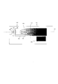
- FIG. 18 schematically shows a temperature distribution generated in the modulator housing 1704 when the optical modulator 1700 is mounted on a circuit board 1802 of an optical module together with, for example, a DSP 1800 which is a heat-generating electronic component.
- Black and white shading superimposed on the illustrated modulator housing 1704 indicates the temperature of each part, and the whiter the temperature, the lower the temperature, and the darker the temperature, the higher the temperature.
- heat from the DSP 1800 arranged on the lower right of the circuit board 1802 mainly propagates through the circuit board 1802, and the heat from the portion of the lower side of the modulator housing 1704 facing the DSP 1800 starts from the portion facing the DSP 1800. It flows into the housing 1704. Then, the heat that has flowed in from this portion propagates toward the entire modulator housing 1704 to the upper left in the figure.
- a temperature gradient is generated in the modulator housing 1704 such that the temperature decreases from the lower right to the upper left as shown in the figure.
- a temperature gradient does not occur when the entire temperature of the modulator housing 1704 changes with a change in the environmental temperature, and the DSP 1800 is unevenly distributed at an asymmetric position with respect to the modulator housing 1704. Occurs due to acting as a heat source. More specifically, this temperature gradient is due to the fact that the size of the DSP 1800 is generally smaller than the size of the modulator housing 1704, and that the DSP 1800 is located close to some of the sides of the modulator housing 1704. I do.
- the DSP 1800 acts as an asymmetrical unevenly distributed heat source as described above.
- the temperature gradient is equal to the center line 1720 with respect to the width direction of the modulator housing 1704 and the center line 1722 with respect to the longitudinal direction. It occurs along different directions 1804 (white dashed arrows in the figure), causing an asymmetric temperature distribution in the modulator housing 1704.
- Such an asymmetric temperature distribution in the modulator housing 1704 is caused by a temperature change expected by the conventional design idea of the modulator housing 1704 of “suppressing deformation by making the wall thickness of the four sides the same”, that is, This is significantly different from “uniform temperature change” in the modulator housing 1704, and may cause characteristic fluctuations and long-term reliability that exceed the designer's prediction.
- This temperature gradient causes the DSP 1800 to act as an asymmetric unevenly distributed heat source as described above, and as a result, the center line 1720 with respect to the width direction of the modulator housing 1704 and the center line 1722 with respect to the longitudinal direction as shown in FIG. This occurs along a direction 1804 (white dashed arrow in the drawing) that is different from the direction, and generates an asymmetric temperature distribution in the modulator housing 1704.
- Such an asymmetrical temperature distribution in the modulator housing 1704 causes a situation in which the design concept of the conventional modulator housing 1704, which is "suppressing deformation by making the wall thicknesses of the four sides the same", that is, the modulation This is significantly different from “uniform temperature change" in the housing 1704, and may cause characteristic fluctuations and long-term reliability lower than expected by the designer.
- a constant temperature chamber set at various temperatures for example, 100 ° C., 125 ° C., etc.
- An optical modulator to be tested is placed in each of the optical modulators, and the characteristic variation of each optical modulator is measured each time a predetermined elapsed time comes. That is, what is predicted from such an accelerated deterioration test is the long-term reliability when the optical modulator 1700 is continuously used at a uniform temperature. Therefore, the long-term reliability of the optical modulator 1700 in a situation where an asymmetric temperature distribution occurs in the optical module as described above may be significantly different from the above prediction.
- an asymmetric temperature distribution also occurs in the plane of the substrate constituting the light modulation element 1702. Accordingly, in particular, when the interferometric light modulator such as the Mach-Zehnder light modulator is used as the light modulator 1702 as described above, an asymmetric temperature distribution is formed between adjacent parallel waveguides on the substrate. Due to this, an additional phase difference different from each other occurs, which may have an unfavorable effect on the characteristics and reliability of the light modulation element 1702 itself.
- the asymmetric temperature distribution generated over a long period of time due to the close arrangement with the heat-generating electronic components causes the characteristic fluctuation and reliability that could not be foreseen in an accelerated deterioration test or the like. It is expected that the decline will occur particularly significantly.
- the heat flowing into the modulator housing from the heat-generating electronic components is reduced by the optical modulation elements and lenses such as lenses disposed in the modulator housing. It can easily propagate to the mounting position of the component, cause a characteristic change as an optical modulator, and reduce long-term reliability.
- One embodiment of the present invention includes a light modulation element including an optical waveguide formed over a substrate and a housing that houses the light modulation element, and the housing has a quadrilateral shape in plan view.
- the light modulating element is fixed to one short side wall, and the light modulating element is disposed such that a first end in a longitudinal direction of the light modulating element faces the first short side wall, and the housing is provided with the first light modulating element.
- At least a part of the light input / output unit which is a range from the outer surface of the one short side wall to the first end of the light modulation element, has a higher thermal resistance than a part of the housing other than the light input / output unit. It has a high heat resistance part.
- an average thickness of the first short side wall is smaller than an average thickness of each of the first long side wall and the second long side wall other than the light input / output section.
- the first short side wall is formed and constitutes the high thermal resistance portion.
- the first long side wall has an average of a portion of the first long side wall other than the light input / output portion, at least in a part of the portion included in the light input / output portion.
- the thin wall portion constitutes the high heat resistance portion.
- the bottom wall is formed to be thinner than an average thickness of the bottom wall in a part other than the light input / output unit, at least in a part included in the light input / output unit. It has a third thin wall portion, and the third thin wall portion of the bottom wall forms the high thermal resistance portion.
- an optical component is disposed on the third thin wall portion of the bottom wall.
- at least one of the optical components disposed on the third thin wall portion of the bottom wall is connected to the third thin wall portion of the bottom wall via a separate pedestal. Fixed to.
- the housing has a rear portion which is a range from a second end facing the first end of the light modulation element to an inner surface of the second short side wall,
- a drive circuit for driving the light modulation element is provided, and the bottom wall is formed such that an average thickness at the rear portion is larger than an average thickness at the light input / output portion, or
- the long side wall or the second long side wall is formed such that an average thickness at the back portion is larger than an average thickness at the light input / output portion.
- an optical component is fixed to the first end of the light modulation element, and the bottom wall has an inner surface having a height different from an outer surface of the bottom wall.
- a step portion connecting the two planes, and the light modulation element is arranged on the bottom wall such that the first end protrudes from the step portion.
- Another embodiment of the present invention is an optical module including any one of the above-described optical modulators and an electronic component. This specification includes all contents of Japanese Patent Application No. 2018-124467 filed on June 29, 2018.
- the optical modulator even when a heat source such as an electronic component is disposed close to the optical modulator, it is possible to suppress a change in characteristics and / or a decrease in long-term reliability.
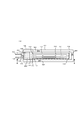
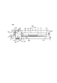
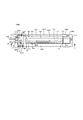
- FIG. 1 is a plan view of the optical modulator according to the first embodiment of the present invention.
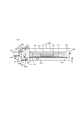
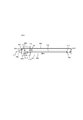
- FIG. 2 is an AA cross-sectional view of the optical modulator shown in FIG.
- FIG. 3 is a diagram illustrating an example of a temperature distribution generated in a modulator housing when the optical modulator illustrated in FIG. 1 is mounted on a circuit board.
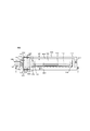
- FIG. 4 is a plan view of an optical modulator according to the second embodiment of the present invention.
- FIG. 5 is a sectional view of the optical modulator shown in FIG.
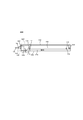
- FIG. 6 is a plan view of an optical modulator according to the third embodiment of the present invention.
- FIG. 7 is a cross-sectional view of the optical modulator shown in FIG.
- FIG. 8 is a plan view of an optical modulator according to the fourth embodiment of the present invention.
- FIG. 9 is a sectional view of the optical modulator shown in FIG.
- FIG. 10 is a plan view of an optical modulator according to a fifth embodiment of the present invention.
- FIG. 11 is an EE sectional view of the optical modulator shown in FIG.
- FIG. 12 is a plan view of an optical modulator according to the sixth embodiment of the present invention.
- FIG. 13 is an FF cross-sectional view of the optical modulator shown in FIG.
- FIG. 14 is a plan view of the optical modulator according to the seventh embodiment of the present invention.
- FIG. 15 is a GG sectional view of the optical modulator shown in FIG.
- FIG. 16 is a plan view of an optical module according to the eighth embodiment of the present invention.
- FIG. 17 is a plan view showing a configuration of a conventional optical modulator.
- FIG. 18 is a diagram illustrating an example of a temperature distribution generated in a modulator housing when a conventional optical modulator is mounted on a circuit board.
- the present invention configures an optical modulator in which the proximity arrangement with a heat-generating electronic component is avoided in the related art as an optical device capable of the close arrangement, and also actively improves a thermal environment in the optical module. It opens the way for use as a device that can contribute.
- the thickness of the side wall of the modulator housing is adjusted so that the modulator housing itself actively acts as a heat sink or a good heat conductor.
- a housing configuration in which heat is easily transmitted to the entire light modulation element is adopted.
- the optical input / output unit on which the optical components are mounted is configured to be hard to conduct heat. This avoids asymmetrical temperature distribution in the light modulation element, avoids heat conduction to the optical components, and avoids fluctuations in characteristics and long-term reliability of the light modulator as a whole.
- the optical modulator of the present invention faces the one wall from the outer surface of the one wall on which the input optical fiber and the output optical fiber are arranged, of the modulator housing constituting the optical modulator. At least a part of the input / output section extending to one end of the light modulation element is provided with a high thermal resistance section having a higher thermal resistance than a part of the modulator housing other than the optical input / output section.
- the optical modulator according to the present embodiment has an average thickness of one wall of the modulator housing in which the input optical fiber and the output optical fiber are arranged, and the average thickness of each of the two walls connected to both sides of the one wall. , Which are formed thinner than the average thickness of portions other than the input / output portion to constitute a high thermal resistance portion.
- FIG. 1 is a plan view showing the configuration of the optical modulator 100 according to the first embodiment of the present invention
- FIG. 2 is a cross-sectional view of the optical modulator 100 taken along the line AA.
- the light modulator 100 includes a light modulation element 102, a modulator housing 104 that houses the light modulation element 102, an input optical fiber 108 that inputs light to the light modulation element 102, and light output from the light modulation element 102. And an output optical fiber 110 for guiding the light to the outside of the modulator housing 104.
- the modulator housing 104 Since the modulator housing 104 is airtightly sealed, the inside of the modulator housing 104 cannot actually be visually recognized. However, in FIG. 1, the configuration inside the modulator housing 104 is understood. For simplicity, the components inside the modulator housing 104 are shown by solid lines.
- the modulator housing 104 is made of metal (for example, stainless steel, Kovar, or the like), and is rectangular or quadrilateral (for example, rectangular or substantially rectangular) in plan view. That is, the modulator housing 104 includes a first short side wall 120 and a second short side wall connected to the bottom wall 128 having a quadrilateral shape in a plan view and the other two opposite sides (left and right sides in the drawing) of the bottom wall 128. And a side wall 122. Further, the modulator housing 104 is provided on two opposing sides (upper and lower sides in FIG. 1) of the bottom wall 128 that are longer than the first short side wall 120 and the second short side wall 122. A first long side wall 124 and a second long side wall 126 are connected. The light modulation element 102 is housed in a space surrounded by the first short side wall 120, the second short side wall 122, the first long side wall 124, the second long side wall 126, and the bottom wall 128. .
- the end facing the first short side wall 120 where the light input terminal 150 and the light output terminal 152, which will be described later, are arranged is referred to as a first end 140, a first end 140. Is defined as a second end 142. Therefore, the second end 142 faces the second short side wall 122.
- a line extending in the left-right direction in the figure along the center of the modulator housing 104 in the width direction is a center line 130 with respect to the width direction
- a line extending in the vertical direction in the figure along the center in the longitudinal direction is defined as a center line 132 with respect to the longitudinal direction.
- the light modulation element 102 is a waveguide type light modulator composed of an optical waveguide formed on a substrate.
- the light modulation element 102 is configured by, for example, an optical waveguide provided on a LiNbO 3 substrate.
- the light modulation element 102 includes an input waveguide 112 into which light from the input optical fiber 108 is incident, a modulation unit 114 including an optical waveguide group that performs an optical modulation operation, and a light provided at the second end 142. It has a light reflection film 116 that constitutes a folded portion.
- the modulation unit 114 performs a modulation operation by causing light propagating in a plurality of optical waveguides extending in the longitudinal direction of the light modulation element 102 to interfere with each other, for example.
- the modulation unit 114 includes four Mach-Zehnder optical waveguides and four RF (Radio Frequency) electrodes (not shown) provided on the Mach-Zehnder optical waveguide and modulating a light wave propagating in the optical waveguide.
- a DP-QPSK optical modulator comprising:
- the first end 140 of the optical modulation element 102 is an optical input / output end to which the light from the input optical fiber 108 is input to the input waveguide 112 and the light modulated by the modulator 114 is output.
- the second end 142 on the right side in the drawing is a light turning end where light is turned back by the light reflecting film 116.
- a microlens array 118 as an optical component is fixed to the first end 140 by, for example, bonding.
- a glass block 144 for reinforcing the adhesive strength of the optical component is fixed to the substrate surface near the first end 140 by, for example, bonding.
- An optical input terminal 150 for holding the input optical fiber 108 and an optical output terminal 152 for holding the output optical fiber 110 are fixed to the first short side wall 120 of the modulator housing 104.
- a lens 154 which is an optical component for collimating the light from the input optical fiber 108, is disposed inside the light input terminal 150.
- a lens 158 and an optical polarization combining unit 156 which are optical components, are arranged.
- the polarization combining unit 156 is composed of a wave plate and a polarization combining prism, and outputs two lights (in the case of a DP-QPSK modulator, orthogonal X-axis ports and Y-axis ports) output from the modulation unit 114 of the light modulation element 102. (Port polarization) is polarization-combined and output as one light.
- the lens 158 collects the light output from the polarization combining unit 156 and inputs the collected light to the output optical fiber 110.
- the light input from the input optical fiber 108 is collimated by the lens 154 in the optical input terminal unit 150, and then is collimated by the microlens array 118 provided at the first end 140 of the light modulation element 102.
- the light is condensed and input to the input waveguide 112 of the light modulation element 102.
- the light input to the input waveguide 112 is reflected by the light reflecting film 116 at the second end 142, and is input to the modulator 114.
- the light input to the modulator 114 is modulated by the modulator 114 and then output from the first end 140.
- the light from the modulating unit 114 output from the first end 140 is collimated by the microlens array 118 and is polarized by the polarization combining unit 156 in the optical output terminal unit 152.
- the polarized light is condensed by the lens 158 in the optical output terminal unit 152, coupled to the output optical fiber 110, and guided to the outside of the modulator housing 104 by the output optical fiber 110.
- FIG. 2 also shows a cover 160 that constitutes a part of the modulator housing 104 in the opening at the upper part of the modulator housing 104 in the drawing.
- the cover 160 is provided with a first short side wall 120, a second short side wall 122, and a first long side wall in FIG. For example, seams are welded to four sides of the second long side wall 126.
- a plurality of lead pins for inputting a high-frequency signal for operating the light modulation element 102, and a high-frequency signal input from the plurality of lead pins are applied to the RF electrode of the light modulation element 102.
- a relay board or the like for guiding each of them may be provided (neither is shown). Therefore, irregularities are formed on the inner surfaces of the first short side wall 120, the second short side wall 122, the first long side wall 124, the second long side wall 126, and / or the bottom wall 128 of the modulator housing 104. Can be provided.
- the first short side wall 120 and the second short side of the modulator housing 104 are shown in FIGS.
- the wall 122, the first long side wall 124, the second long side wall 126, and the bottom wall 128 are described as having a uniform thickness.
- FIGS. 4 to 15 should be understood to be the same.
- the wall thickness t1 of the first short side wall 120 on the left side of the modulator housing 104 is the first long side wall 124 and the second long side wall 124.
- 126 is thinner (that is, a smaller value) than the wall thicknesses t2 and t3 of the portion other than the light input / output unit 162, which is a range from the outer surface of the first short side wall 120 to the first end 140 of the light modulation element 102. ) Is formed. That is, t1 ⁇ t2 and t1 ⁇ t3.
- the optical modulator 100 when the optical modulator 100 is mounted on a circuit board in the optical module, one of the first long side wall 124 and the second long side wall 126 having the wall thicknesses t2 and t3 is provided by the circuit.
- the heat-generating electronic components mounted on the substrate are arranged so as to face the side on which, for example, a DSP is mounted.
- FIGS. 1 and 2 do not show irregularities for disposing lead pins, relay boards, and the like, which may be provided in the actual modulator housing 104. . Therefore, the wall thickness of the first short side wall 120, the second short side wall 122, the first long side wall 124, the second long side wall 126, and the bottom wall 128 shown in FIGS. In some cases, it should be understood to indicate the average wall thickness at each wall. That is, in the present embodiment, the wall thickness t1 is an average value of the wall thickness of the first short side wall 120.
- the wall thicknesses t2 and t3 are the average values of the wall thicknesses of the first long side wall 124 and the second long side wall 126 other than the light input / output unit 162, respectively.
- wall thickness in this specification refers to the average value (average wall thickness) of the wall thickness of the corresponding wall or a part of the wall, unless otherwise specified.
- the “average value” of the wall thickness refers to an average value of a corresponding wall or a partial thickness of the wall, and is a case where the wall or the wall portion is connected to or intersects with an adjacent wall. This also refers to the average value of the thickness of the so-called “wall” itself or the portion of the "wall” itself, not including the connection or intersection.
- the curved portion Means the average value of the thickness of the "wall” itself or the "wall” itself.
- the wall thickness t2 of the first long side wall 124 and the wall thickness t3 of the second long side wall 126 in portions other than the light input / output unit 162 have a lower thermal resistance than the long side wall in the conventional optical modulator.
- the wall thickness t1 of the first short side wall 120 is set in a range of, for example, 0.5 mm or more and 1.0 mm or less.
- the modulator casing 104 can be used as a heat sink for heat-generating electronic components arranged in close proximity by using the modulator casing 104 as a propagation path for heat flowing from the outside.
- the first long side wall 124 and the third long side wall are configured to have irregularities
- the first long side wall 124 and the third long side wall are each formed to have a thickness of 1.7 mm to 4 mm.
- the wall thicknesses t2 and t3, which are the respective average wall thicknesses may be set in a range of 2.0 mm or more and 3.0 mm or less.
- the first short side wall 120 has a configuration having irregularities
- the first short side wall 120 is formed in a range of 0.3 mm to 1 mm in thickness
- the wall thickness t1 which is the average wall thickness, is reduced.
- the value may be set in a range of 0.5 mm or more and 1.0 mm or less.
- the wall thickness t2 of the first long side wall 124 and the wall thickness t3 of the second long side wall 126 are set to be thicker than the conventional optical modulator.
- the thermal resistance of the first long side wall 124 and the second long side wall 126 along the long side of the 104 is reduced, and the temperature gradient in the longitudinal direction of the modulator housing 104 is reduced by a conventional optical modulator (for example, FIG. 17 (light modulator 1700). If the temperature gradient in the longitudinal direction of the modulator housing 104 is reduced in this way, the direction of the temperature gradient when viewed as a whole of the modulator housing 104 is longer than the direction 1804 shown in FIG. It is a direction close to the direction. As a result, it is possible to suppress an asymmetric temperature distribution of the entire optical modulator 100 including the optical modulation element 102, and to suppress a characteristic variation and a decrease in long-term reliability.
- the optical modulator 100 can be used as a device that can positively contribute to the improvement of the thermal environment in the optical module by using the optical modulator 100 as a heat sink and / or a good thermal conductor of the heat-generating electronic component.
- the above-described effect of suppressing the asymmetric temperature gradient is obtained by setting the wall thickness t2 of the first long-side wall 124 and the wall thickness t3 of the third long-side wall to 2.5 with respect to the conventional average wall thickness of 1.5 mm as described above. It is particularly remarkable when the thickness is in the range of 0 mm or more and 3.0 mm or less, and the wall thickness t1 of the first short side wall 120 is in the range of 0.5 mm or more and 1.0 mm or less. The function as a heat sink is further enhanced.
- the wall thickness t1 of the first short side wall 120 included in the light input / output unit 162 is different from that of the first long side wall 124 and the second long side wall 126 other than the light input / output unit 162.
- the first short side wall 120 itself is formed to be thinner than the wall thicknesses t2 and t3 of the portion, and forms the high thermal resistance portion.
- the optical modulator 100 even when the heat-generating electronic components are arranged close to each other, the optical components such as the input optical fiber 108 and the lens 154 disposed inside the optical input terminal 150 and the optical output terminal 152 are provided.
- the wall thickness t2 of the first long side wall 124 and the wall thickness t3 of the second long side wall 126 are set to be thicker than those of the conventional optical modulator, so that heat-generating electronic components and the like can be used.
- the generated temperature gradient of the modulator housing 104 can be reduced, and the characteristic fluctuation and the long-term reliability can be further suppressed.
- FIG. 3 schematically shows a temperature distribution generated in the modulator housing 104 when the optical modulator 100 is mounted on a circuit board 392 of an optical module together with, for example, a DSP 390 as a heat-generating electronic component.
- Black and white shading superimposed on the modulator casing 104 shown in the figure indicates the temperature of each part, and the whiter the temperature, the lower the temperature, and the darker the temperature, the higher the temperature.
- the temperature gradient along the center line 130 with respect to the width direction becomes gentle.
- the symmetry of the temperature distribution generated in the modulator housing 104 is improved.
- the stress generated in the modulator housing 104 is reduced and dispersed.
- the temperature distribution of the optical modulation device 102 which is an interferometric light modulation device, housed in the modulator housing 104 also has more symmetry. It becomes. As a result, the difference in the optical path length or the phase change between the parallel waveguides forming the light modulation element 102 is reduced, and the characteristic fluctuation (for example, the operation point fluctuation) of the light modulation element 102 is also suppressed.
- the modulator casing 104 in the optical module is placed in a uniform temperature environment as in a long-term reliability test in a thermostat. Approaching the state. Therefore, the long-term reliability of the modulator casing 104 approaches the long-term reliability test result of the thermostat, and can be further improved as compared with the conventional configuration.
- the wall thickness t4 of the second short side wall 122 shown in FIG. 1 and the wall thickness t5 of the portion other than the light input / output unit 162 in the bottom wall 128 shown in FIG. From the viewpoints of heat dissipation, rigidity, and the like, the larger the better, the better. For example, it is desirable that t4> t2 and t4> t3, and t5> t2 and t5> t3, respectively.
- the wall thickness t1 of the first short side wall 120 is made smaller than the wall thickness t2 of the first long side wall 124 and the wall thickness t3 of the second long side wall 126, so that the high thermal resistance portion is formed.
- the material of the first short side wall 120 is changed to the first long side wall 124,
- the second long side wall 126 and / or the bottom wall 128 (more specifically, a material other than the light input / output portion 162 of these walls) is made of another material having a lower thermal conductivity.
- the first short side wall 120 may be configured as a high heat resistance portion.
- the optical modulator according to the present embodiment has an input / output unit which is a range from the outer surface of the first short side wall on which the input optical fiber and the output optical fiber are arranged to the first end of the optical modulation element.
- FIG. 4 is a plan view showing the configuration of the optical modulator 400 according to the second embodiment.
- FIG. 5 is a sectional view of the optical modulator 400 shown in FIG. 4 and 5, the same reference numerals as those in FIGS. 1 and 2 denote the same components and wall thicknesses as those of the optical modulator 100 according to the first embodiment in FIGS. 1 and 2, respectively. It shall be used, and the description of the optical modulator 100 described above shall be cited. Further, in FIG. 4, in order to facilitate understanding of the configuration of the optical modulator 400, similarly to FIG. 1, the internal structure that cannot be visually recognized after the assembly is completed is shown by a solid line.
- the optical modulator 400 has a configuration similar to that of the optical modulator 100, except that a modulator housing 404 is provided instead of the modulator housing 104.
- the modulator housing 404 includes a first short side wall 420 similar to the first short side wall 120, the second short side wall 122, the first long side wall 124, and the second long side wall 126 of the modulator housing 104. , A second short side wall 422, a first long side wall 424, and a second long side wall 426. That is, the first length of the portion other than the light input / output unit 462 where the wall thickness t1 of the first short side wall 420 is in the range from the outer surface of the first short side wall 420 to the first end 140 of the light modulation element 102.
- the wall thickness t2 of the side wall 424 and the wall thickness t3 of the second long side wall 426 are configured such that t1 ⁇ t2 and t1 ⁇ t3.
- the modulator housing 404 is different from the modulator housing 104 in having a bottom wall 428 instead of the bottom wall 128.
- the bottom wall 428 has a thin wall portion having at least a part of the light input / output unit 462 having a wall thickness t52 smaller than the wall thickness t51 of the bottom wall 428 in a part other than the light input / output unit 462. 464 (illustrated dot hatching portion).
- the thin wall portion 464 corresponds to a third thin wall portion.
- FIG. 5 also illustrates a cover 460 that forms a part of the housing 406.
- the modulator housing 404 shown in FIG. 4 has, like the modulator housing 104 shown in FIG. 1, unevenness for arranging lead pins, relay boards, and the like which may be provided in the actual modulator housing 404. Not shown. That is, the wall thickness of the first short side wall 420, the second short side wall 422, the first long side wall 424, the second long side wall 426, and the bottom wall 428 shown in FIG. Should be understood to indicate the average wall thickness at When the thin wall portion 464 is formed of, for example, a plurality of irregularities having different depths and opening sizes, the range of the thin wall portion 464 can be defined as a region including the irregularities.
- the optical modulator 400 having the above configuration, similarly to the optical modulator 100, heat flows along the first long side wall 424 and the second long side wall 426 which are thicker than the wall thickness of the conventional optical modulator.
- the temperature gradient becomes gentle on both the first long side wall 424 side and the second long side wall 426 side, and the symmetry of the temperature distribution generated in the modulator housing 404 is improved. Thereby, even when the optical modulator 400 is arranged close to the heat-generating electronic component, the fluctuation of the characteristics of the optical modulator 400 and the decrease in long-term reliability are suppressed.
- the first short side wall 420 has the first long side wall 424 and the second long side wall 424 other than the light input / output unit 462.
- the side wall 426 is formed with a wall thickness t1 smaller than the wall thicknesses t2 and t3, and forms a high thermal resistance portion.
- a thin wall portion 464 having a wall thickness t52 smaller than the wall thickness t51 of the portion other than the light input / output portion 462 is formed also on the bottom wall 428 to constitute a high thermal resistance portion.
- the heat flowing into the light input terminal 150 and the light output terminal 152 from the bottom wall 428 through the first short side wall 420 by the thin wall portion 464 is also suppressed, and the light modulation is performed.
- the optical modulator 100 it is possible to suppress the occurrence of the characteristic fluctuation and the decrease in the long-term reliability of the optical modulator 400.
- a thin wall portion 464 is provided on the bottom wall 428 to form a high heat resistance portion.
- the high heat resistance portion may be constituted only by the thin wall portion 464 of the bottom wall 428, and the first short side wall 420 may be constituted by a wall thickness equivalent to t2 and t3.
- the material of the first short side wall 420 is used to configure a portion other than the light input / output unit 462.
- the first short side wall 420 is configured as a high thermal resistance portion by using a material having a lower thermal conductivity than the material of the first long side wall 424, the second long side wall 426, and / or the bottom wall 428. It may be.
- the material of the portion of the bottom wall 428 corresponding to the thin wall portion 464 is replaced with the first long side wall constituting the portion other than the light input / output portion 462.
- the material corresponding to the thin wall portion 464 may be configured as a high thermal resistance portion by using a material having a lower thermal conductivity than that of the portion of the 424, the second long side wall 426, and / or the bottom wall 428. .
- the optical modulator according to this embodiment includes an outer surface of the first short side wall of each of the first long side wall and the second long side wall connected to the first short side wall on which the input optical fiber and the output optical fiber are arranged. And at least a part of the light input / output unit in the range from the light input / output unit to the first end of the light modulation element. It has a first thin wall portion and a second thin wall portion having a smaller average wall thickness. The first thin wall portion and the second thin wall portion constitute a high heat resistance portion as a characteristic configuration.
- FIG. 6 is a plan view showing the configuration of the optical modulator 600 according to the third embodiment.
- FIG. 7 is a cross-sectional view of the optical modulator 600 shown in FIG. 6 and 7, the same reference numerals as those in FIGS. 1 and 2 are used for the same components as those in the optical modulator 100 according to the first embodiment in FIGS. 1 and 2, respectively.
- the description of the optical modulator 100 described above is referred to.
- FIG. 6 in order to facilitate understanding of the configuration of the optical modulator 600, the internal structure that cannot be visually recognized after the assembly is completed is indicated by solid lines, as in FIG.
- FIG. 7 also shows a cover 660 that forms a part of the modulator housing 604, which is not shown in FIG.
- the optical modulator 600 has the same configuration as that of the optical modulator 100, except that the optical modulator 600 includes a modulator housing 604 instead of the modulator housing 104.
- the modulator housing 604 is similar to the first short side wall 120, the second short side wall 122, the first long side wall 124, the second long side wall 126, and the bottom wall 128 of the modulator housing 104, respectively. It has a first short side wall 620, a second short side wall 622, a first long side wall 624, a second long side wall 626, and a bottom wall 628.
- the first short side wall 620 has a range of light from the outer surface of the first short side wall 620 of the first long side wall 624 and the second long side wall 626 to the first end 140 of the light modulation element 102.
- Portions other than the input / output unit 662 are configured to have a wall thickness t11 smaller than the wall thicknesses t21 and t31 to form a high thermal resistance unit.
- the bottom wall 628 has a thin wall portion 664 (dots shown in the drawing) having a wall thickness t54 smaller than a wall thickness t53 of a portion of the bottom wall 628 other than the light input / output portion 662 at least at a part of the light input / output portion 662. (A hatched portion) is formed.
- first long side wall 624 has at least a part of the light input / output unit 662 with a wall thickness t22 that is smaller than the wall thickness t21 of the portion other than the light input / output unit 662 in the first long side wall 624.
- a thin wall portion 670 (hatched right oblique portion in the figure) is formed.
- the second long side wall 626 has at least a part of the light input / output unit 662 with a wall thickness t32 that is smaller than the wall thickness t31 of the portion other than the light input / output unit 662 in the second long side wall 626.
- a thin wall portion 672 (a left oblique hatching portion in the figure) is formed.
- the thin wall portions 670, 672, and 664 correspond to the first thin wall portion, the second thin wall portion, and the third thin wall portion, respectively.
- the optical modulator 600 having the above configuration, as in the optical modulator 100, heat flows along the first long side wall 624 and the second long side wall 626, which are thicker than the wall thickness of the conventional optical modulator.
- the temperature gradient is gentle on both the first long side wall 624 side and the second long side wall 626 side, and the symmetry of the temperature distribution generated in the modulator housing 604 is improved.
- the optical modulator 600 since the first short side wall 620 and the thin wall portions 664, 670, and 672 constitute a high thermal resistance portion, when the optical modulator 600 is mounted on an optical module or the like, modulation is performed from a DSP or the like which is a heat-generating electronic component. Heat flowing into the housing 604 can be effectively suppressed from flowing into the light input terminal 150 and the light output terminal 152. Thus, the optical modulator 600 can further suppress the occurrence of characteristic fluctuations and / or a decrease in long-term reliability of the optical modulator 600 as compared with the optical modulator 100.
- the first long side wall 624 and the second long side wall 626 are configured such that the wall thicknesses t21 and t31 satisfy t21 ⁇ t31.
- Such a configuration is convenient when, for example, when the optical modulator 600 is mounted on the optical module, it can be defined that the heat-generating electronic component is mounted on one of the long side walls.
- the wall thickness of the long side wall for example, the second long side wall 626 in the present embodiment
- these two long side walls are formed. In this case, the heat from the heat-generating electronic components can be more effectively transmitted to the circuit board with the same weight as compared with the configuration in which the wall thicknesses are the same.
- the thin wall portions 664, 670, 672 are provided, but the present invention is not limited to this. Even if only the thin wall portions 670 and 672 are provided without providing the thin wall portion 664, a certain suppression effect can be obtained with respect to the above-mentioned characteristic fluctuation and reliability reduction.
- the optical modulator according to the present embodiment has the same configuration as the optical modulator 600 according to the third embodiment, and an optical component is disposed on the thin wall portion 664 of the bottom wall 628.
- FIG. 8 is a plan view showing the configuration of the optical modulator 800 according to the fourth embodiment
- FIG. 9 is a cross-sectional view of the optical modulator 800 shown in FIG. 8 and 9, the same components as those of the optical modulator 600 according to the third embodiment in FIGS. 6 and 7 and the optical modulator 100 according to the first embodiment in FIGS.
- the same reference numerals as those in FIGS. 6 and 7 and FIGS. 1 and 2 are used, and the description of the optical modulators 400 and 100 described above is used.
- FIG. 8 in order to facilitate understanding of the configuration of the optical modulator 800, similarly to FIGS. 1 and 4, the internal structure that cannot be visually recognized when assembly is completed is indicated by solid lines. I have.
- the optical modulator 800 has the same configuration as the optical modulator 600, but includes an optical output terminal 852 instead of the optical output terminal 152, and includes a high thermal resistance portion of the bottom wall 628 of the modulator housing 604. The difference is that an optical component group 876 is arranged on the thin wall portion 664 to be configured.
- the optical output terminal unit 852 has the same configuration as the optical output terminal unit 152, but differs from the optical output terminal unit 152 in that the optical output terminal unit 852 does not include the polarization combining unit 156.
- the optical component group 876 includes, for example, optical components having the same function as the optical components such as the polarization combining unit 156 disposed in the optical output terminal unit 152 of the optical modulator 600, and includes, for example, a wave plate and a polarization combining unit. Prism included.
- arranging optical components in an optical output terminal unit is advantageous for downsizing an optical modulator, but restricts the size, shape, and / or characteristics of the optical components, and limits the choice of optical components. Will be done. Further, as compared with a configuration in which the optical components are disposed in the modulator housing, the distance from the light output end face of the light modulation element to the optical components is longer, so that the light emitted from the light modulation element due to temperature fluctuation or the like is emitted. Even if the angle fluctuates slightly, the point of incidence of light on the optical component fluctuates greatly, and the temperature characteristics of the optical characteristics tend to deteriorate.
- the optical component group 876 is disposed on the thin wall portion 664 of the bottom wall 628 of the modulator housing 604, for example, a polarization combining prism, a wavelength plate, or the like constituting the optical component group 876.
- the restrictions on the shape (size) and characteristics (for example, dependence on the light incident point) are relaxed. For this reason, options of these optical components are expanded.
- the distance from the first end 140 of the light modulation element 102 to the optical component group 876 having, for example, a polarization combining prism or the like is smaller. It is possible to do. For this reason, a change in optical characteristics with respect to a change in the emission angle of light from the light modulation element 102 due to a temperature change can also be suppressed.
- the optical component group 876 may include one or a plurality of optional optical components according to the function required of the optical modulator 800 and the like.
- the output optical fiber 110 may be drawn into the interior of the modulator housing 604, and the lens 158 disposed in the light output terminal portion 852 may be included in the optical component group 876.
- the input optical fiber 108 may be drawn into the interior of the modulator housing 604, and the lens 154 provided in the optical input terminal 150 may be included in the optical component group 876.
- the optical modulator according to the present embodiment has the same configuration as the optical modulator 800 according to the fourth embodiment, and at least one of the optical components arranged on the thin wall portion 664 of the bottom wall 628 is different from the optical modulator 800 according to the fourth embodiment. It is characterized in that it is fixed to the thin wall portion 664 via a pedestal formed of a body.
- FIG. 10 is a plan view showing the configuration of the optical modulator 1000 according to the fifth embodiment
- FIG. 11 is a cross-sectional view of the optical modulator 1000 shown in FIG.
- the same components and wall thicknesses as those of the optical modulator 800 according to the fourth embodiment in FIGS. 8 and 9 are denoted by the same reference numerals as those in FIGS.
- the description of the optical modulator 800 described above is referred to.
- FIG. 10 in order to facilitate understanding of the configuration of the optical modulator 1000, similarly to FIG. 8, the internal structure that cannot be visually recognized after the assembly is completed is indicated by a solid line.
- the optical modulator 1000 has the same configuration as the optical modulator 600, but the optical component group 876 is attached to the thin wall portion 664 of the bottom wall 628 of the modulator housing 604, which constitutes a high thermal resistance portion, via the base 1078. Is different.
- a pedestal 1078 made of a material having low thermal conductivity (for example, ceramic or the like) is sandwiched between the thin wall portion 664 of the bottom wall 628 and the optical component group 876. And two thermal interfaces can be sandwiched (i.e., the interface between thin wall 664 and pedestal 1078 and the interface between pedestal 1078 and optics group 876). . For this reason, heat conduction from the thin wall portion 664 to the optical component can be largely suppressed.
- the optical modulator 1000 after mounting an optical component group 876 including a plurality of optical components on the pedestal 1078, the optical components 1000 are assembled on the pedestal 1078, and the pedestal 1078 and The group of optical components 876 can be disposed on the thin wall portion 664 of the bottom wall 628. For this reason, the handling of the optical component is facilitated, the number of manufacturing steps can be reduced, and the manufacturing variation can be reduced.
- all of the optical components arranged on the thin wall portion 664 constitute an optical component group 876 and are fixed on the thin wall portion 664 via the pedestal 1078.
- At least one of the optical components disposed on the thin wall portion 664 constitutes an optical component group 876 according to the heat resistance of the optical components, the ease of adjustment when manufacturing the optical modulator 1000, and the like. , May be fixed on the thin wall portion 664 via the pedestal 1078.
- the optical modulator according to the present embodiment has an optical modulator on a rear portion which is a range from a second end facing the first end of the optical modulator to an inner surface of the second short side wall of the modulator housing. Is provided as a characteristic configuration. Further, the bottom wall of the modulator housing has an average thickness at the back portion that is greater than an average thickness at the light input / output portion that is in a range from the outer surface of the first short side wall to the first end of the light modulation element. It is also characterized in that the first long side wall or the second long side wall is formed to be thicker, and the average thickness at the rear portion is larger than the average thickness at the light input / output portion. Is included.
- FIG. 12 is a plan view showing the configuration of an optical modulator 1200 according to the sixth embodiment
- FIG. 13 is a cross-sectional view of the optical modulator 1200 shown in FIG. 12 and 13, the same reference numerals as those in FIGS. 10 and 11 are used for the same components and wall thicknesses as those of the optical modulator 1000 according to the fifth embodiment in FIGS.
- the description of the optical modulator 1000 described above is referred to.
- FIG. 12 in order to facilitate understanding of the configuration of the optical modulator 1200, the internal structure that cannot be visually recognized in a state where the assembly is completed is shown by a solid line, similarly to FIG.
- the optical modulator 1200 has the same configuration as the optical modulator 1000, but differs in that a modulator housing 1204 is provided instead of the modulator housing 604.
- the modulator housing 1204 is similar to the first short side wall 620, the second short side wall 622, the first long side wall 624, the second long side wall 626, and the bottom wall 628 of the modulator housing 604. It has one short side wall 1220, a second short side wall 1222, a first long side wall 1224, a second long side wall 1226, and a bottom wall 1228.
- the first short side wall 1220 is a range of the first long side wall 1224 and the second long side wall 1226 from the outer surface of the first short side wall 1220 to the first end 140 of the light modulation element 102. It is formed so as to have a wall thickness t12 smaller than the wall thicknesses t25 and t35 of the portion other than the light input / output unit 1262, and constitutes a high thermal resistance unit.
- the bottom wall 1228 has a thin wall portion 1264 having a wall thickness t56 smaller than a wall thickness t55 of a portion other than the light input / output portion of the bottom wall 1228 on at least a part of the light input / output portion 1262. Is formed. Note that FIG. 13 also illustrates a cover 1260 that forms a part of the modulator housing 1204 whose description is omitted in FIG.
- the first long side wall 1224 further includes at least a part of the light input / output unit 1262, a wall thinner than the wall thickness t ⁇ b> 25 of a portion of the first long side wall 1224 other than the light input / output unit 1262.
- a thin wall portion 1270 having a thickness t26 is formed.
- the second long side wall 1226 has a thin wall thickness t36 at at least a part of the light input / output unit 1262 that is smaller than a wall thickness t35 of a portion of the second long side wall 1226 other than the light input / output unit 1262.
- a wall 1272 is formed.
- the thin wall portions 1270, 1272, and 1264 correspond to the first thin wall portion, the second thin wall portion, and the third thin wall portion, respectively, and constitute high heat resistance portions.
- an optical component group 876 is fixed via a pedestal 1078.
- a drive circuit for driving the light modulation element 102 is provided on a rear portion 1280 that extends from the second end 142 of the light modulation element 102 to the inner surface of the second short side wall 1222.
- a driver IC 1282 is provided.
- the bottom wall 1228 of the modulator housing 1204 has a wall thickness t57 of the rear portion 1280 that is equal to a wall thickness t58 of the optical input / output unit 1262 (that is, an average wall thickness of the optical input / output unit 1262). It is formed thicker than a certain wall thickness t58).
- the first long side wall 1224 and the second long side wall 1226 have wall thicknesses t27 and t37 of the rear portion 1280, respectively, and wall thicknesses t28 and t38 of the light input / output unit 1262 (that is, the light input / output unit 1262). It is formed to be thicker than the respective average wall thicknesses t28 and t38).
- the optical modulator 1200 having the above configuration, similarly to the optical modulator 100, heat flows along the first long side wall 1224 and the second long side wall 1226 which are thicker than the wall thickness of the conventional optical modulator.
- the temperature gradient becomes gentle on both the first long side wall 1224 side and the second long side wall 1226 side, and the symmetry of the temperature distribution generated in the modulator housing 1204 is improved.
- the optical modulator 1200 is arranged close to the heat-generating electronic components, the fluctuation of the characteristics of the optical modulator 1200 and the decrease in long-term reliability are suppressed.
- the optical modulator 1200 has a thin wall portion 1264 and the like constituting a high thermal resistance portion, similarly to the optical modulators 100, 400, 600, 800, and 1000 according to the first to fifth embodiments. Variations in characteristics and a decrease in long-term reliability when the heat-generating electronic components are arranged close to each other can be suppressed.
- the driver IC 1282 for driving the optical modulation element 102 is disposed adjacent to the optical modulation element 102, the transmission distance of the high-frequency signal from the driver IC 1282 to the optical modulation element 102 And the high-frequency characteristics of the entire light modulation operation can be greatly improved.
- the driver IC 1282 is generally a heat-generating electronic component that can generate heat of about 1 W.
- the driver IC 1282 is disposed close to the outside of the optical modulator in the optical module as in the related art, the driver IC 1282 is unevenly distributed with respect to the optical modulator. Acting as a heat source to generate an asymmetric temperature distribution in the housing of the optical modulator.
- the driver IC 1282 is disposed on the rear portion 1280 of the modulator housing 1204 facing the optical input / output portion 1262, and the wall thickness t57 of the bottom wall 1228 of the rear portion 1280 is provided.
- first long side wall 1224 and the second long side wall 1226 have wall thicknesses t27 and t37 of the rear portion 1280 on which the driver IC 1282 is disposed, respectively.
- the second long side wall 1226 is formed to be thicker than the wall thicknesses t28 and t38.
- the heat generated by the driver IC 1282 can flow substantially symmetrically in the width direction of the modulator housing 1204, and the temperature distribution of the modulator housing 1204 caused by the heat is substantially symmetric. Can be generated. That is, in the optical modulator 1200, the driver IC 1282 which acts as a heat source unevenly distributed in the related art is arranged at a position inside the modulator housing 1204 where no asymmetrical temperature distribution is generated. The heat environment of the driver IC 1282 can be secured while improving the thermal environment of the modulator 1200 itself.
- the wall thickness t57 of the rear wall 1280 of the bottom wall 1228 is formed to be thicker than the wall thickness t58 of the light input / output unit 1262, and the first long side wall 1224 and the second long side wall 1224 are formed.
- the wall thicknesses t27 and t37 of the rear portion 1280 are formed to be thicker than the wall thicknesses t28 and t38 of the light input / output unit 1262, respectively, but this is not a limitation.
- the modulator housing 1204 is That the bottom wall 1228 has a wall thickness t57 at the rear portion 1280 that is greater than the wall thickness t58 of the light input / output unit 1262;
- the first long side wall 1224 is formed such that the wall thickness t27 at the back portion 1280 is larger than the wall thickness t28 at the light input / output unit 1262; or If the second long side wall 1226 has one of the requirements that the wall thickness t37 of the rear portion 1280 is larger than the wall thickness t38 of the light input / output portion 1262, the same effect as described above is provided. Can be obtained at a certain level.
- an optical component is fixed to the first end of the light modulation element, and the bottom wall of the modulator housing has a different height on the inner surface from the outer surface of the bottom wall.
- the light modulating element includes two planes, and the light modulating element is arranged on the bottom wall such that the first end protrudes from a step formed by the two planes.
- FIG. 14 is a plan view showing the configuration of an optical modulator 1400 according to the seventh embodiment
- FIG. 15 is a sectional view of the optical modulator 1400 shown in FIG. 14 and 15, the same components and wall thicknesses as those of the optical modulator 1200 according to the sixth embodiment in FIGS. 12 and 13 use the same reference numerals as those in FIGS. 12 and 13.
- the above description of the optical modulator 1200 is referred to.
- FIG. 14 in order to facilitate understanding of the configuration of the optical modulator 1400, similarly to FIG. 12, an internal structure that cannot be visually recognized in a state where the assembly is completed is shown by a solid line.
- the micro lens array 118 as an optical component is fixed to the first end 140 of the optical modulation element 102 by, for example, bonding.
- the optical modulator 1400 has the same configuration as the optical modulator 1200, except that the optical modulator 1400 includes a modulator housing 1404 instead of the modulator housing 1204.
- the modulator housing 1404 is similar to the first short side wall 1220, the second short side wall 1222, the first long side wall 1224, the second long side wall 1226, and the bottom wall 1228 of the modulator housing 1204. It has a first short side wall 1420, a second short side wall 1422, a first long side wall 1424, a second long side wall 1426, and a bottom wall 1428.
- the first short side wall 1420 is a range from the outer surface of the first short side wall 1420 to the first end 140 of the light modulation element 102 among the first long side wall 1424 and the second long side wall 1426. It is formed so as to have a wall thickness t12 smaller than the wall thicknesses t25 and t35 of the portion other than the light input / output unit 1462, and constitutes a high thermal resistance unit.
- the bottom wall 1428 has a thin wall portion having at least a part of the light input / output unit 1462 having a wall thickness t56 smaller than a wall thickness t55 of a portion of the bottom wall 1428 other than the light input / output unit 1462. 1464 are formed. Note that FIG. 15 also illustrates a cover 1460 that constitutes a part of the modulator housing 1404, the description of which is omitted in FIG.
- the first long side wall 1424 has at least a part of the light input / output unit 1462 provided with a wall thinner than the wall thickness t25 of a portion of the first long side wall 1424 other than the light input / output unit 1462.
- a thin wall portion 1470 having a thickness t26 is formed.
- the second long side wall 1426 has a thin wall thickness t36 which is smaller than the wall thickness t35 of a portion of the second long side wall 1426 other than the light input / output unit 1462 in at least a part of the light input / output unit 1462.
- a wall 1472 is formed.
- the thin wall portions 1470, 1472, and 1464 correspond to the first thin wall portion, the second thin wall portion, and the third thin wall portion, respectively, and constitute high heat resistance portions.
- an optical component group 876 is fixed via a pedestal 1078.
- a drive circuit for driving the light modulation element 102 is provided on a rear portion 1480 of the modulator housing 1404, which is a range from the second end 142 of the light modulation element 102 to the inner surface of the second short side wall 1422.
- a driver IC 1282 is provided.
- the bottom wall 1428 of the modulator housing 1404 has a wall thickness t57 of the rear portion 1480 that is greater than a wall thickness t59 of the light input / output unit 1462 (that is, a wall thickness t59 that is an average wall thickness of the light input / output unit 1462). It is also formed thick. Further, the first long side wall 1424 and the second long side wall 1426 have wall thicknesses t27 and t37 of the rear portion 1480, respectively, and wall thicknesses t29 and t39 of the light input / output unit 1462 (that is, the light input / output unit 1462). It is formed to be thicker than the respective average wall thicknesses t29 and t39).
- the bottom wall 1428 of the modulator housing 1404 is formed on the inner surface thereof as two planes having different heights from the outer surface of the bottom wall 1428 on the upper surface of the thin wall portion 1464 in FIG. It has a certain thin-walled inner surface 1484 and a modulator fixing surface 1486 to which the light modulation element 102 is fixed.
- the thin wall inner surface 1484 and the modulator fixing surface 1486 constitute a step portion 1488.
- the light modulation element 102 modulates the bottom wall 1428 such that the first end 140 protrudes in the direction of the thin wall inner surface 1484 from the step 1488 formed by the thin wall inner surface 1484 and the modulator fixing surface 1486.
- the container fixing surface 1486 is provided.
- the optical modulator 1400 since the first end portion 140 of the optical modulation element 102 protrudes from the step portion 1488, the optical modulator 1400 is an optical component that is relatively sensitive to heat and temperature.
- the fixing portion between the lens array 118 and the first end 140 is separated from the bottom wall 1428. Thereby, heat conduction to the fixing portion is further suppressed. As a result, fluctuations in characteristics and a decrease in long-term reliability due to the close arrangement of the heat-generating electronic components are further suppressed.
- the micro lens array 118 is shown as an optical component fixed to the first end 140, but the present invention is not limited to this.
- An arbitrary optical component can be fixed to the first end 140 of the light modulation element 102.
- Such an optical component is, for example, one or more of a wave plate, a glass plate for a spacer, a lens, a prism, a PBC, a wave plate, a collimator, an anisotropic crystal, a sapphire plate, a glass plate, and a capillary. can do.
- the wall thicknesses t59, t29, and t39 which are the average wall thickness in the light input / output unit 1462, are different.
- the thin wall portions 1470 and 1472 may be provided on at least a part of the light input / output unit 1462.
- one of the two planes which the bottom wall 1428 of the modulator housing 1404 has on its inner surface is constituted by the thin wall inner surface 1484 which is the upper surface of the thin wall portion 1464.
- One of the two planes may be a plane formed in the light input / output unit 1462 other than the thin wall inner surface 1484, as long as it forms a step with at least the modulator fixing surface 1486. it can.
- the thin wall portion 1464 may be formed not in the entire area of the light input / output section 1462 but in at least a part thereof.
- This embodiment is an optical module including the optical modulator according to any of the above-described embodiments and an electronic component.
- FIG. 16 is a plan view showing a configuration of an optical module 1600 according to the eighth embodiment.
- the optical module 1600 houses the optical modulator 800 and the circuit board 1606 in the optical module housing 1602.
- an LD (Laser @ Diode) 1608 as a light source of transmission light and a PD (Photo @ Diode) 1610 as a light receiver of reception light are mounted on the circuit board 1606, in addition to the optical modulator 800.
- LD Laser @ Diode
- PD Photo @ Diode
- FIG. 16 shows a DSP 1612 for digital signal processing as an example of an electronic component that is a main electronic component and generates a large amount of heat.
- optical module 1600 can be mounted on the circuit board 1606 according to the functions required for the optical module 1600.
- electronic components include, for example, a driver IC for driving the optical modulator 100 and the like.
- the optical module 1600 outputs, for example, signal light (transmission light) to one transmission line optical fiber (not shown) via the optical modulator 800, and transmits the other transmission line optical fiber (not shown).
- the received optical signal (received light) is received by the PD 1610.
- the optical modulator 800 is arranged such that the DSP 1612 is arranged close to the second long side wall 626 having a greater wall thickness than the first long side wall 624 with a predetermined interval g.
- the interval g is, for example, 5 mm.
- the optical module 1600 having the above configuration uses the optical modulator 800 in which the characteristic fluctuation and the long-term reliability deterioration due to the close arrangement of the heat-generating electronic components are used, so that the optical modulator 800 is separated from the electronic components. It is possible to maintain a high transmission quality of the transmission light output from the optical module 1600 while suppressing downsizing of the optical module 1600 by relaxing the restriction on the distance, and to suppress a decrease in long-term reliability of the optical module 1600 as a whole. it can.
- the optical module 1600 is configured by using the optical modulator 800, but is not limited thereto.
- the optical modulator 100, 400, 600, 1000, 1200, or 1400 is arranged at the same position as the optical modulator 800 on the circuit board 1606 shown in FIG. You may comprise.
- the optical modulator 100 and the like include the optical modulator 102 including the optical waveguide formed on the substrate and the modulator housing 104 and the like that house the optical modulator.
- the modulator housing 104 and the like include a bottom wall 128 and the like having a quadrilateral shape in plan view, a first short side wall 120 and a second short side wall 122 and the like connected to two opposing sides of the bottom wall 128 and the like, The first long side wall 124 and the second long side wall which are longer than the first short side wall 120 and the like and the second short side wall 122 and the like and are connected to the other two opposite sides such as the bottom wall 128 etc. 126 and the like.
- the light modulation element 102 is located in a space surrounded by the bottom wall 128, the first long side wall 124, the second long side wall 126, and the like, and the first short side wall 120, the second short side wall 122, and the like. Is housed in Also, an optical input terminal unit 150 that holds an input optical fiber 108 for inputting light to the light modulation element 102 and an output optical fiber 110 that guides light output from the light modulation element 102 to the outside such as the modulator housing 104 are provided. The held light output terminal 152 and the like are both fixed to the first short side wall 120 and the like. Further, the light modulation element 102 is arranged such that the first end 140 in the longitudinal direction of the light modulation element 102 faces the first short side wall 120 or the like.
- the modulator housing 104 and the like are connected to at least a part of the optical input / output unit 162 or the like extending from the outer surface of the first short side wall 120 or the like to the first end 140 of the optical modulation element 102. It has a high thermal resistance portion having a higher thermal resistance than portions of the modulator housing 104 and the like other than the portion 162 and the like.
- the optical modulator 100 and the like are arranged close to the heat-generating electronic components such as the DSP 390 in the optical module as the optical communication device, the symmetry of the temperature distribution generated in the modulator housing 104 is achieved. And suppressing the propagation of heat to the first short side wall 120 or the like where the optical fiber or the optical component can be arranged, thereby suppressing the characteristic fluctuation and / or the long-term reliability decrease in the optical modulator 100 and the like. Can be.
- the wall thickness of the modulator housing 104 or the like other than the optical input / output section 162 or the like is increased while suppressing characteristic fluctuations and long-term reliability deterioration. Since the heat of the heat-generating electronic components can be transmitted, the optical modulator 100 and the like can be used as a heat sink and / or a good heat conductor that can positively contribute to the improvement of the thermal environment in the optical module.
- the wall thickness t11 of the first short side wall 120 is equal to the wall thicknesses t2 and t3 of the first long side wall 124 and the second long side wall 126 other than the light input / output unit 162.
- the first short side wall 120 is formed to be thinner and constitutes a high thermal resistance portion. According to this configuration, while improving the symmetry of the temperature distribution generated in the modulator housing 104 and further configuring the first short side wall 120 itself as a high thermal resistance portion, the input optical fiber 108 and the output optical fiber It is possible to suppress the flow of heat into the optical components such as the lens 110 and the lens 154, and to suppress the fluctuation of the characteristics of the optical modulator 100 and the decrease in long-term reliability.
- the first long side wall 624 has at least a part of a portion included in the light input / output unit 662, and a wall thickness of a portion of the first long side wall 624 other than the light input / output unit 662. It has a thin wall portion 670 which is a first thin wall portion having a wall thickness t22 smaller than t21.
- the second long side wall 626 has a wall thickness t32 that is smaller than a wall thickness t31 of a portion of the second long side wall 626 other than the light input / output unit 662 in at least a part of the portion included in the light input / output unit 662.
- a thin wall portion 672 that is a second thin wall portion having The thin wall portion 670 of the first long side wall 624 and the thin wall portion 672 of the second long side wall 626 constitute a high thermal resistance portion.
- a part of the first long side wall 624 and the second long side wall 626 of the modulator housing 604 is configured as a high thermal resistance portion, and the optical modulator is allowed to be disposed close to the heat-generating electronic components. While using the light modulator 600 as a heat sink and / or a good heat conductor, it is possible to further suppress a change in the characteristics of the optical modulator 600 and a decrease in long-term reliability.
- the bottom wall 428 has a wall thickness t52 that is smaller than a wall thickness t51 of the bottom wall 428 in a portion other than the light input / output unit 462 at least in a part included in the light input / output unit 462.
- a portion of the bottom wall 428 of the modulator housing 404 is configured as a high thermal resistance portion, and the optical modulator 600 is used as a heat sink and / or a good thermal conductor by allowing close proximity to the heat-generating electronic components. It is possible to further suppress the characteristic fluctuation and the long-term reduction in reliability of the optical modulator 600 while using it.
- an optical component such as a polarization-combining prism is provided on a thin wall portion 664 that is a third thin wall portion that forms a high thermal resistance portion provided on the bottom wall 628.
- a group 876 is provided.
- the optical component group 876 composed of at least one of the optical components disposed on the thin wall portion 664 of the bottom wall 628 is separated from the thin bottom wall 628 via a pedestal 1078 which is a separate body. It is fixed on the wall 664. According to this configuration, since thermal boundaries can be sandwiched between the thin wall portion 664 and the pedestal 1078 and between the pedestal 1078 and the optical component group 876, heat can flow into the optical components. By suppressing this, it is possible to suppress the characteristic fluctuation and the decrease in long-term reliability. In addition, since a plurality of optical components can be configured as one optical component group 876 on the pedestal 1078, the number of manufacturing steps can be reduced and manufacturing variations can be reduced.
- the light modulating element 102 is provided on the rear portion 1280, which is a range from the second end 142 facing the first end 140 of the light modulating element 102 to the inner surface of the second short side wall 1222.
- a driver IC 1282 including a drive circuit for driving.
- the bottom wall 1228 is formed such that the wall thickness t57 of the rear portion 1280 is thicker than the wall thickness t58 of the bottom wall 1228 of the light input / output unit 1262, or the first long side wall 1224 or the second long side.
- the wall 1226 is formed such that the wall thickness t27 or t37 of the rear portion 1280 is greater than the wall thickness t28 or t38 of the light input / output unit 1262, respectively.
- the driver IC 1282 is provided inside the modulator housing 1204, high-frequency characteristics can be improved. Further, since the driver IC 1282 can be arranged at a position symmetrical with respect to the width direction of the modulator housing 1204, the asymmetry in the modulator housing 1204 due to the arrangement of the driver IC 1282 in the modulator housing 1204 is achieved. By suppressing the occurrence of a temperature distribution, it is possible to suppress the characteristic fluctuation and the decrease in long-term reliability.
- the microlens array 118 which is an optical component, is fixed to the first end 140 of the light modulation element 102, and the bottom wall 1428 is formed on the inner surface thereof from the outer surface of the bottom wall 1428. It has a step 1488 composed of a thin wall inner surface 1484 and a modulator fixing surface 1486 which are two planes having different heights.
- the light modulation element 102 is arranged on the modulator fixing surface 1486 of the bottom wall 1428 so that the first end 140 protrudes from the step 1488. According to this configuration, the heat flowing into the microlens array 118 and the fixed portion at the first end 140 of the light modulation element 102 can be suppressed, and the characteristic fluctuation and the long-term reliability can be further suppressed.
- the optical module 1600 according to the present invention includes the optical modulator 800 according to the first to seventh embodiments and electronic components such as the DSP 1612. According to this configuration, since the optical modulator 800 or the like in which the characteristic fluctuation and the long-term reliability decrease due to the close arrangement of the heat-generating electronic components are used is used, the distance between the optical modulator 800 and the electronic components is reduced. It is possible to maintain a high transmission quality of the transmission light output from the optical module 1600 while reducing the size of the optical module 1600 by relaxing the restrictions, and also suppress a decrease in long-term reliability of the optical module 1600 as a whole.
- an optical modulator can be configured by arbitrarily combining one or more of the characteristic configurations described in the first to seventh embodiments.
- the light modulation element 102 is configured by the optical waveguide formed on the LiNbO 3 substrate, but is not limited thereto.
- the light modulation element 102 may be formed of a semiconductor such as InP, or may be formed of an optical element of Si photonics.
- the light modulator element has a smaller casing than an optical modulation element using a semiconductor such as InP.
- the size in the longitudinal direction is increased, it is possible to more suitably exert the effect of suppressing the fluctuation of characteristics and the deterioration of long-term reliability, and the effect as a heat sink and / or a good heat conductor for heat-generating electronic components.
- the input optical fiber 108 and the output optical fiber 110 are both fixed to the first short side wall 120 or the like, light is turned back by the light reflecting film 116 at the second end 142.
- the light modulation element 102 used is used, it is not limited to this.
- a light modulation element having an arbitrary configuration can be used.
- the light modulation element 102 as described in Patent Document 1, the light modulation element and the optical component forming the light turning section may be configured as separate parts.
- a configuration may be adopted in which a bent waveguide formed of a PLC or the like is provided at one end of the light modulation element as a light turnback unit.
- Optical modulator 100, 400, 600, 800, 1000, 1200, 1400, 1700: Optical modulator, 102, 1702: Optical modulator, 104, 404, 604, 1204, 1404, 1704: Modulator housing, 108, 1708: Input Optical fiber, 110, 1710 output optical fiber, 112 input waveguide, 114 modulation part, 116 light reflection film, 118 microlens array, 120, 420, 620, 1220, 1420 first short side wall, 122, 422, 622, 1222, 1422 ... second short side wall, 124, 424, 624, 1224, 1424 ... first long side wall, 126, 426, 626, 1226, 1426 ...
- second long side wall, 128, 428, 628, 1228, 1428 bottom wall, 130, 1720: center line in the width direction, 132, 1722 ... Center line to hand direction, 140: first end, 142: second end, 144: glass block, 150: light input terminal, 152, 852: light output terminal, 154, 158: lens, 156: polarized Wave synthesizer, 160, 460, 660, 1260, 1460 ... cover, 162, 462, 662, 1262, 1462 ... light input / output unit, 390, 1612, 1800 ... DSP, 392, 1606, 1802 ... circuit board, 464, 664, 670, 672, 1264, 1270, 1272, 1464, 1470, 1472 ...
- thin wall portion 876 ... optical component group, 1078 ... pedestal, 1280, 1480 ... rear portion, 1282 ... driver IC, 1484 ... thin wall inner surface, 1486: modulator fixing surface, 1488: step portion, 1600: optical module, 1602: optical module housing, 1 08 ... LD, 1610 ... PD, 1712 ... light folded portion, 1714 ... output optical system.
Landscapes
- Physics & Mathematics (AREA)
- Nonlinear Science (AREA)
- General Physics & Mathematics (AREA)
- Optics & Photonics (AREA)
- Chemical & Material Sciences (AREA)
- Engineering & Computer Science (AREA)
- Ceramic Engineering (AREA)
- Crystallography & Structural Chemistry (AREA)
- Optical Modulation, Optical Deflection, Nonlinear Optics, Optical Demodulation, Optical Logic Elements (AREA)
Abstract
La présente invention porte sur un module optique pouvant supprimer une variation et/ou une réduction de caractéristique de fiabilité à long terme qui sont dues à l'agencement rapproché d'un composant électronique produisant de la chaleur. Ledit module optique comporte un élément de modulation optique configuré à partir d'un guide d'ondes optique, et un boîtier. Le boîtier comprend une paroi inférieure qui revêt une forme quadrilatérale en vue en plan, des première et seconde parois latérales courtes reliées à deux côtés de la paroi inférieure opposés l'un à l'autre, et des première et seconde parois latérales longues reliées à deux côtés de la paroi inférieure opposés l'un à l'autre. Une partie borne d'incidence de lumière qui maintient une fibre de lumière d'entrée et une partie borne de sortie de lumière qui maintient une fibre de lumière de sortie sont toutes deux fixées à la première paroi latérale courte. Dans au moins une partie de la zone d'entrée/de sortie de lumière, qui part de la surface extérieure de la première paroi latérale courte à une première borne de l'élément de modulation optique faisant face à la première paroi latérale courte, le boîtier comprend une partie résistance thermique élevée qui présente une résistance thermique plus élevée que les parties du boîtier extérieures à ladite zone d'entrée/de sortie de lumière.
Priority Applications (2)
| Application Number | Priority Date | Filing Date | Title |
|---|---|---|---|
| CN201980043240.0A CN112334821B (zh) | 2018-06-29 | 2019-06-28 | 光调制器以及使用此光调制器的光模块 |
| US17/256,396 US11194181B2 (en) | 2018-06-29 | 2019-06-28 | Optical modulator and optical module using this |
Applications Claiming Priority (2)
| Application Number | Priority Date | Filing Date | Title |
|---|---|---|---|
| JP2018-124467 | 2018-06-29 | ||
| JP2018124467A JP7172184B2 (ja) | 2018-06-29 | 2018-06-29 | 光変調器、及びこれを用いた光モジュール |
Publications (1)
| Publication Number | Publication Date |
|---|---|
| WO2020004637A1 true WO2020004637A1 (fr) | 2020-01-02 |
Family
ID=68987168
Family Applications (1)
| Application Number | Title | Priority Date | Filing Date |
|---|---|---|---|
| PCT/JP2019/025883 Ceased WO2020004637A1 (fr) | 2018-06-29 | 2019-06-28 | Modulateur optique et module optique mettant en œuvre ce dernier |
Country Status (4)
| Country | Link |
|---|---|
| US (1) | US11194181B2 (fr) |
| JP (1) | JP7172184B2 (fr) |
| CN (1) | CN112334821B (fr) |
| WO (1) | WO2020004637A1 (fr) |
Cited By (3)
| Publication number | Priority date | Publication date | Assignee | Title |
|---|---|---|---|---|
| WO2022071381A1 (fr) * | 2020-09-30 | 2022-04-07 | 住友大阪セメント株式会社 | Élément de guide d'ondes optique, et dispositif de modulation optique et appareil de transmission optique l'utilisant |
| WO2023053403A1 (fr) * | 2021-09-30 | 2023-04-06 | 住友大阪セメント株式会社 | Élément de guide d'ondes optique, et appareil de transmission optique et dispositif de modulation optique l'utilisant |
| WO2025203387A1 (fr) * | 2024-03-27 | 2025-10-02 | 住友大阪セメント株式会社 | Dispositif optique et dispositif de transmission optique |
Families Citing this family (5)
| Publication number | Priority date | Publication date | Assignee | Title |
|---|---|---|---|---|
| JP7484230B2 (ja) * | 2020-03-04 | 2024-05-16 | 富士通オプティカルコンポーネンツ株式会社 | 光モジュール |
| JP7367579B2 (ja) * | 2020-03-23 | 2023-10-24 | 住友大阪セメント株式会社 | 光機能デバイス |
| JP7452190B2 (ja) | 2020-03-31 | 2024-03-19 | 住友大阪セメント株式会社 | 光導波路素子及びそれを用いた光変調デバイス並びに光送信装置 |
| JP7380389B2 (ja) | 2020-03-31 | 2023-11-15 | 住友大阪セメント株式会社 | 光導波路素子及びそれを用いた光変調デバイス並びに光送信装置 |
| JP7666069B2 (ja) | 2021-03-30 | 2025-04-22 | 住友大阪セメント株式会社 | 光導波路素子及びそれを用いた光変調デバイス並びに光送信装置 |
Citations (5)
| Publication number | Priority date | Publication date | Assignee | Title |
|---|---|---|---|---|
| US20130308898A1 (en) * | 2012-04-26 | 2013-11-21 | Acacia Communications Inc. | Co-packaging photonic integrated circuits and application specific integrated circuits |
| JP2015069162A (ja) * | 2013-09-30 | 2015-04-13 | 住友大阪セメント株式会社 | 光変調器 |
| JP2015102786A (ja) * | 2013-11-27 | 2015-06-04 | 住友大阪セメント株式会社 | 光学素子モジュール |
| JP2016200763A (ja) * | 2015-04-13 | 2016-12-01 | 日本電信電話株式会社 | 光集積回路型光デバイス |
| JP2018072605A (ja) * | 2016-10-31 | 2018-05-10 | 富士通オプティカルコンポーネンツ株式会社 | 光変調器及び光モジュール |
Family Cites Families (2)
| Publication number | Priority date | Publication date | Assignee | Title |
|---|---|---|---|---|
| JP4359582B2 (ja) * | 2005-08-31 | 2009-11-04 | 日本電信電話株式会社 | 光モジュール |
| JP2016099508A (ja) | 2014-11-21 | 2016-05-30 | 住友電気工業株式会社 | 光トランシーバの製造方法 |
-
2018
- 2018-06-29 JP JP2018124467A patent/JP7172184B2/ja active Active
-
2019
- 2019-06-28 WO PCT/JP2019/025883 patent/WO2020004637A1/fr not_active Ceased
- 2019-06-28 CN CN201980043240.0A patent/CN112334821B/zh active Active
- 2019-06-28 US US17/256,396 patent/US11194181B2/en active Active
Patent Citations (5)
| Publication number | Priority date | Publication date | Assignee | Title |
|---|---|---|---|---|
| US20130308898A1 (en) * | 2012-04-26 | 2013-11-21 | Acacia Communications Inc. | Co-packaging photonic integrated circuits and application specific integrated circuits |
| JP2015069162A (ja) * | 2013-09-30 | 2015-04-13 | 住友大阪セメント株式会社 | 光変調器 |
| JP2015102786A (ja) * | 2013-11-27 | 2015-06-04 | 住友大阪セメント株式会社 | 光学素子モジュール |
| JP2016200763A (ja) * | 2015-04-13 | 2016-12-01 | 日本電信電話株式会社 | 光集積回路型光デバイス |
| JP2018072605A (ja) * | 2016-10-31 | 2018-05-10 | 富士通オプティカルコンポーネンツ株式会社 | 光変調器及び光モジュール |
Cited By (6)
| Publication number | Priority date | Publication date | Assignee | Title |
|---|---|---|---|---|
| WO2022071381A1 (fr) * | 2020-09-30 | 2022-04-07 | 住友大阪セメント株式会社 | Élément de guide d'ondes optique, et dispositif de modulation optique et appareil de transmission optique l'utilisant |
| JP2022056981A (ja) * | 2020-09-30 | 2022-04-11 | 住友大阪セメント株式会社 | 光導波路素子及びそれを用いた光変調デバイス並びに光送信装置 |
| JP7468280B2 (ja) | 2020-09-30 | 2024-04-16 | 住友大阪セメント株式会社 | 光導波路素子及びそれを用いた光変調デバイス並びに光送信装置 |
| WO2023053403A1 (fr) * | 2021-09-30 | 2023-04-06 | 住友大阪セメント株式会社 | Élément de guide d'ondes optique, et appareil de transmission optique et dispositif de modulation optique l'utilisant |
| US12607803B2 (en) | 2021-09-30 | 2026-04-21 | Sumitomo Osaka Cement Co., Ltd. | Optical waveguide element, and optical transmission apparatus and optical modulation device using same |
| WO2025203387A1 (fr) * | 2024-03-27 | 2025-10-02 | 住友大阪セメント株式会社 | Dispositif optique et dispositif de transmission optique |
Also Published As
| Publication number | Publication date |
|---|---|
| CN112334821A (zh) | 2021-02-05 |
| JP2020003701A (ja) | 2020-01-09 |
| US20210157176A1 (en) | 2021-05-27 |
| US11194181B2 (en) | 2021-12-07 |
| CN112334821B (zh) | 2024-08-27 |
| JP7172184B2 (ja) | 2022-11-16 |
Similar Documents
| Publication | Publication Date | Title |
|---|---|---|
| WO2020004637A1 (fr) | Modulateur optique et module optique mettant en œuvre ce dernier | |
| CN214795475U (zh) | 光波导元件、使用光波导元件的光调制器件及光发送装置 | |
| JP3353718B2 (ja) | 光通信モジュール | |
| US6865006B2 (en) | Optical modulator module | |
| CN113424087B (zh) | 光模块 | |
| JP7163478B2 (ja) | 光導波路、平面型光回路および光源モジュール | |
| JP5420388B2 (ja) | 光モジュール、光モジュールの製造方法及び光モジュールの調整方法 | |
| CN112639587B (zh) | 光调制器及使用了该光调制器的光模块 | |
| CN112397993A (zh) | 一种窄线宽外腔激光器及光模块 | |
| CN110133807A (zh) | 光模块及光模块的制造方法 | |
| JP7172185B2 (ja) | 光変調器、及びこれを用いた光モジュール | |
| US20240069367A1 (en) | Optical module | |
| CN112310805A (zh) | 一种窄线宽外腔激光器及光模块 | |
| WO2019176210A1 (fr) | Bloc d'ajustement de trajet lumineux, module lumineux et procédé de fabrication de module lumineux | |
| JP2025146284A (ja) | 光モジュール | |
| JP7139653B2 (ja) | 光デバイス | |
| JP2018017852A (ja) | 光変調器 | |
| CN118805105A (zh) | 光波导元件、使用光波导元件的光调制器件及光发送装置 | |
| CN117130143A (zh) | 光学模块 | |
| JP2008047701A (ja) | 光モジュール | |
| JP2021077711A (ja) | 光モジュール | |
| JP2019207362A (ja) | 光モジュール | |
| JP2006119661A (ja) | 光源内蔵型光変調器モジュール | |
| JP2006147769A (ja) | 光素子用キャップ、光素子および光モジュール | |
| JP2003243758A (ja) | 半導体レーザモジュール |
Legal Events
| Date | Code | Title | Description |
|---|---|---|---|
| 121 | Ep: the epo has been informed by wipo that ep was designated in this application |
Ref document number: 19825975 Country of ref document: EP Kind code of ref document: A1 |
|
| NENP | Non-entry into the national phase |
Ref country code: DE |
|
| 122 | Ep: pct application non-entry in european phase |
Ref document number: 19825975 Country of ref document: EP Kind code of ref document: A1 |