WO2020008501A1 - Bottleneck detecting device and bottleneck detecting program - Google Patents
Bottleneck detecting device and bottleneck detecting program Download PDFInfo
- Publication number
- WO2020008501A1 WO2020008501A1 PCT/JP2018/025065 JP2018025065W WO2020008501A1 WO 2020008501 A1 WO2020008501 A1 WO 2020008501A1 JP 2018025065 W JP2018025065 W JP 2018025065W WO 2020008501 A1 WO2020008501 A1 WO 2020008501A1
- Authority
- WO
- WIPO (PCT)
- Prior art keywords
- production
- model
- production process
- period
- bottleneck
- Prior art date
- Legal status (The legal status is an assumption and is not a legal conclusion. Google has not performed a legal analysis and makes no representation as to the accuracy of the status listed.)
- Ceased
Links
Images






Classifications
-
- G—PHYSICS
- G05—CONTROLLING; REGULATING
- G05B—CONTROL OR REGULATING SYSTEMS IN GENERAL; FUNCTIONAL ELEMENTS OF SUCH SYSTEMS; MONITORING OR TESTING ARRANGEMENTS FOR SUCH SYSTEMS OR ELEMENTS
- G05B19/00—Program-control systems
- G05B19/02—Program-control systems electric
- G05B19/418—Total factory control, i.e. centrally controlling a plurality of machines, e.g. direct or distributed numerical control [DNC], flexible manufacturing systems [FMS], integrated manufacturing systems [IMS] or computer integrated manufacturing [CIM]
-
- Y—GENERAL TAGGING OF NEW TECHNOLOGICAL DEVELOPMENTS; GENERAL TAGGING OF CROSS-SECTIONAL TECHNOLOGIES SPANNING OVER SEVERAL SECTIONS OF THE IPC; TECHNICAL SUBJECTS COVERED BY FORMER USPC CROSS-REFERENCE ART COLLECTIONS [XRACs] AND DIGESTS
- Y02—TECHNOLOGIES OR APPLICATIONS FOR MITIGATION OR ADAPTATION AGAINST CLIMATE CHANGE
- Y02P—CLIMATE CHANGE MITIGATION TECHNOLOGIES IN THE PRODUCTION OR PROCESSING OF GOODS
- Y02P90/00—Enabling technologies with a potential contribution to greenhouse gas [GHG] emissions mitigation
- Y02P90/02—Total factory control, e.g. smart factories, flexible manufacturing systems [FMS] or integrated manufacturing systems [IMS]
Definitions
- the present invention relates to a technique for finding a device that becomes a bottleneck in a variety and variable production.
- Patent Document 1 proposes such a method.
- the number of sheets that can be processed by the apparatus per day (the number of sheets that can be processed) and the number of sheets that can be processed per day to achieve a production plan (the number of processed sheets) are calculated. Then, a device whose number of processable sheets is less than the required number of processed sheets is determined as a bottleneck device.
- the required number of processed sheets per day is 80 for model 1 and 50 for model 2.
- simply comparing the number of sheets that can be processed in one day with the number of sheets that can be processed in one day for each model indicates that the production of one model will reduce the processing capacity of the apparatus A for the production of the other model. The reduction is not reflected in the bottleneck determination. Therefore, it is difficult to determine an appropriate bottleneck device. Further, as the number of models increases, it becomes more difficult to determine an appropriate bottleneck.
- the present invention has an object to specify a bottleneck device even in a variant and variable production in which a plurality of models are produced during a target period.
- the bottleneck detection device of the present invention A process in which a production process is performed for each set of a model and a production process based on the production deadline for each model, the number of productions for each model, and the processing time per unit for each production process in the production procedure for each model.
- a processing period determining unit for determining a period A use device determining unit that determines a production device used in the production process as a use device for each set of a model and a production process based on production device data indicating one or more production devices for each production process; A processing time for each set of the model and the production process, and a use time calculation unit for calculating the use time of the production apparatus in the target period for each production device based on the used device for each set of the model and the production process, A bottleneck detection unit that finds a production device that becomes a bottleneck in the target period based on the usage time of each production device in the target period.
- the present invention it is possible to specify a bottleneck device even in a variant and variable production in which a plurality of models are produced during a target period.
- FIG. 2 is a configuration diagram of a bottleneck detection device 100 according to the first embodiment.
- FIG. 2 is a schematic diagram of a bottleneck detection method according to the first embodiment.
- 5 is a flowchart of a bottleneck detection method according to the first embodiment.
- FIG. 4 is a diagram showing a specific example of production plan data 121 according to the first embodiment.
- FIG. 4 is a diagram showing a specific example of production procedure data 122 according to the first embodiment.
- FIG. 4 is a diagram showing a specific example of production device data 123 according to the first embodiment.
- FIG. 4 is a diagram showing a specific example of usage period data 124 according to the first embodiment.
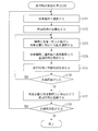
- 9 is a flowchart of a determination process (S110) according to the first embodiment.
- FIG. 110 determination process
- FIG. 4 is a diagram showing a specific example of usage time data 125 according to the first embodiment.
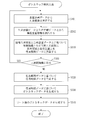
- 9 is a flowchart of a usage time calculation process (S120) according to the first embodiment.
- FIG. 4 is a diagram showing a specific example of bottleneck data 126 according to the first embodiment.
- 9 is a flowchart of a bottleneck detection process (S130) according to the first embodiment.
- 9 is a flowchart of a bottleneck detection method according to the second embodiment.
- FIG. 14 is a diagram showing a specific example of production procedure data 122 according to the second embodiment.
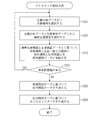
- 13 is a flowchart of a determination process (S210) according to the second embodiment.
- FIG. 9 is a configuration diagram of a bottleneck detection device 100 according to a third embodiment.
- FIG. 11 is a schematic diagram of a bottleneck detection method according to the third embodiment.
- 15 is a flowchart of a bottleneck detection method according to the third embodiment.
- FIG. 2 is a hardware configuration
- Embodiment 1 FIG. An embodiment in which a device that becomes a bottleneck in variant and variable production will be described with reference to FIGS.
- the configuration of the bottleneck detection device 100 is a computer including hardware such as a processor 101, a memory 102, an auxiliary storage device 103, a communication device 104, and an input / output interface 105. These hardwares are connected to each other via signal lines.
- the processor 101 is an IC (Integrated Circuit) that performs arithmetic processing, and controls other hardware.
- the processor 101 is a CPU (Central Processing Unit), a DSP (Digital Signal Processor), or a GPU (Graphics Processing Unit).
- the memory 102 is a volatile storage device.
- the memory 102 is also called a main storage device or a main memory.
- the memory 102 is a RAM (Random Access Memory).
- the data stored in the memory 102 is stored in the auxiliary storage device 103 as needed.
- the auxiliary storage device 103 is a nonvolatile storage device.
- the auxiliary storage device 103 is a ROM (Read Only Memory), a HDD (Hard Disk Drive), or a flash memory.
- the data stored in the auxiliary storage device 103 is loaded into the memory 102 as needed.
- the communication device 104 is a receiver and a transmitter.
- the communication device 104 is a communication chip or a NIC (Network Interface Card).
- the input / output interface 105 is a port to which an input device and an output device are connected.
- the input / output interface 105 is a USB terminal, the input device is a keyboard and a mouse, and the output device is a display.
- USB is an abbreviation for Universal Serial Bus.
- the bottleneck detection device 100 includes elements such as an information extraction unit 111, a processing period determination unit 112, a use device determination unit 113, a use time calculation unit 114, and a bottleneck detection unit 115. These elements are realized by software.
- the auxiliary storage device 103 stores a bottleneck detection program for causing a computer to function as the information extraction unit 111, the processing period determination unit 112, the use device determination unit 113, the use time calculation unit 114, and the bottleneck detection unit 115. I have.
- the bottleneck detection program is loaded into the memory 102 and executed by the processor 101.
- the auxiliary storage device 103 stores an OS (Operating System). At least a part of the OS is loaded into the memory 102 and executed by the processor 101. That is, the processor 101 executes the bottleneck detection program while executing the OS.
- Data obtained by executing the bottleneck detection program is stored in a storage device such as the memory 102, the auxiliary storage device 103, a register in the processor 101, or a cache memory in the processor 101.
- the auxiliary storage device 103 functions as the storage unit 120. However, another storage device may function as the storage unit 120 instead of the auxiliary storage device 103 or together with the auxiliary storage device 103.
- the bottleneck detection device 100 may include a plurality of processors instead of the processor 101.
- the plurality of processors share the role of the processor 101.
- the bottleneck detection program can be recorded (stored) in a computer-readable manner on a non-volatile recording medium such as an optical disk or a flash memory.
- the operation of the bottleneck detection device 100 corresponds to a bottleneck detection method.
- the procedure of the bottleneck detection method corresponds to the procedure of the bottleneck detection program.
- the information extraction unit 111 extracts, from the production plan data 121, a production deadline and a production number for each model. Further, the information extraction unit 111 extracts, from the production procedure data 122, a processing time per unit number in one or more production processes for each model for each production process.
- the model is the type of article to be produced.
- the model is the type of the semiconductor substrate.
- the production deadline is the final time when production should be completed.
- the production deadline is the delivery date of the product.
- the production number is the number of products to be produced by the production deadline.
- the production number is the number of semiconductor substrates to be produced by the production deadline.
- the product is produced by one or more production processes. In each production process, a certain amount of time (processing time per unit) is required to process a unit number of articles. For example, the number of units of the semiconductor substrate is one.
- the production plan data 121 is data indicating a production deadline and a production number for each model.
- the production plan data 121 is stored in the storage unit 120 in advance.
- the production procedure data 122 is data indicating the processing time per unit number in one or more production processes for each model.
- the production procedure data 122 is stored in the storage unit 120 in advance.
- the processing period determination unit 112 separates the model and the production process based on the production deadline for each model, the number of productions for each model, and the processing time per unit for each production process in the production procedure for each model. Determine the processing period.
- a production procedure includes one or more production steps in an order that is performed.
- the processing period is a period during which the production process is performed for the model.
- the processing period determination unit 112 calculates the processing time for each production process, based on the number of models produced and the processing time per unit for each production process. Then, the processing period determination unit 112 determines the processing period for each production process based on the production deadline of the model and the processing time for each production process for each model. At that time, the processing period determination unit 112 determines the processing period of each production process in reverse order from the last production process.
- the used device determining unit 113 determines the used device for each set of the model and the production process based on the production device data 123.
- the used device is a production device used in the production process for the model.
- the production device data 123 is data indicating one or more production devices for each production process.
- the production device data 123 is stored in the storage unit 120 in advance.
- the usage time calculation unit 114 calculates the usage time of the production device in the target period for each production device based on the processing period for each pair of the model and the production process and the usage device for each combination of the model and the production process. I do.
- the usage time of the production device in the target period is the time during which the production device is used in the target period.
- the target period is a predetermined period. For example, one day's work is performed in three shifts. Alternation times are 0:00, 8:00 and 16:00. In this case, each of the period from 0:00 to 8:00, the period from 8:00 to 16:00, and the period from 16:00 to 24:00 are the target periods.
- the usage time calculation unit 114 determines, for each production device, a group corresponding to the same usage device as the production device among the pair of the model and the production process based on the usage device for each pair of the model and the production process. Select Then, the usage time calculation unit 114 calculates, for each production apparatus, the total sum of the overlapping times of the target period and the processing period of the selected group, based on the processing period for each pair of the model and the production process. The calculated sum is the usage time of the production device in the target period.
- the overlap time between the target period and the processing period is a period of time during which the target period and the processing period overlap.
- the use time calculation unit 114 calculates the use time in the target period for each production device based on the use period data 124. Then, the usage time calculation unit 114 outputs the usage time data 125.
- the use period data 124 is data indicating a processing period for each set of a model and a production process, and a used apparatus for each set of a model and a production process.
- the usage period data 124 is generated by the processing period determination unit 112 and the used device determination unit 113, and is stored in the storage unit 120.
- the use time data 125 is data indicating the use time of each production device in the target period.
- the usage time data 125 is generated by the usage period data 124 and stored in the storage unit 120.
- the bottleneck detection unit 115 finds a production device that becomes a bottleneck in the target period based on the usage time of each production device in the target period. Specifically, the bottleneck detection unit 115 finds a production device that becomes a bottleneck in the target period based on the usage time data 125. Then, bottleneck detecting section 115 outputs bottleneck data 126.
- the bottleneck data 126 is data indicating one or more production devices that become a bottleneck in the target period.
- the bottleneck data 126 is generated by the bottleneck detection unit 115 and stored in the storage unit 120.
- step S101 the information extraction unit 111 selects one unselected model from the production plan data 121.
- the production plan data 121 includes production plan information for each model.
- the production plan information is information indicating a production plan of a model.
- the production plan information includes a model, a production deadline, and a production number.
- the production plan information of the model A001 indicates a production plan of producing 100 semiconductor substrates of the model A001 by 10:00 on March 16, 2018.
- Steps S102 and S110 are executed for the model selected in step S101.
- the model selected in step S101 is called a target model.
- step S102 the information extracting unit 111 extracts model production information of the target model from the production plan data 121 and the production procedure data 122.
- the model production information includes production plan information of the target model and production procedure information of the target model.
- the information extracting unit 111 extracts the production plan information of the target model from the production plan data 121.
- the production plan information indicates the model, the production deadline, and the number of products as described with reference to FIG.
- the information extraction unit 111 extracts the production procedure information of the target model from the production procedure data 122.
- the production procedure data 122 includes production procedure information for each model.
- the production procedure information includes production process information for each production process.
- the production process information is information indicating a production process.
- the production process information includes a process ID, an index, and a processing time per unit.
- the process ID is an identifier for identifying a production process.
- the index is a number indicating the order of the production process.
- the processing time per unit is the time required to process a unit number of articles in the production process.
- the production procedure information of the model A001 includes production process information of the process A, production process information of the process B, and production process information of the process C.
- the production process information of the process A indicates that the process A is the first production process, and that it takes 10 minutes to process the unit of the model A001 by the unit number in the process A.
- the production process information of the process B indicates that the process B is the next production process of the process A, and that it takes 15 minutes to process the unit of the model A001 by the unit number in the process B.
- the production process information of the process C includes information that the process C is the next production process after the process B, that the process C is the final production process, and that the articles of the model A001 are processed by the unit number in the process C. Indicates that it takes 5 minutes.
- step S110 the processing period determination unit 112 determines a processing period for each set of the target model and the production process based on the model production information (production plan information and production procedure information). Then, the processing period determining unit 112 registers the processing period for each set of the target model and the production process in the usage period data 124.
- the used device determining unit 113 determines the used device for each set of the target model and the production process based on the production device data 123. Then, the used device determining unit 113 registers the used device for each set of the target model and the production process in the usage period data 124.
- the production device data 123 indicates one or more production devices for each production process.
- the production process is executed using any one of the production devices associated with the production process.
- the production device data 123 indicates a process ID and one or more device IDs for each production process.
- the process ID is an identifier for identifying a production process.
- the device ID is an identifier for identifying a production device.
- the process A is performed using the device MA001 or the device MA002.
- the use period data 124 indicates a processing period and a production device for each set of a model and a production process.
- the processing period is indicated by a start time and an end time.
- the start time is a time at which the processing period starts.
- the end time is a time at which the processing period ends. For example, in the production of an article of the model A001, the process A is performed from 9:09 on March 16, 2018 to 9:26 on March 16, 2018 using the device MA001.
- step S111 the processing period determination unit 112 selects the final process from the production procedure information of the target model, and determines the selected final process as the target process.
- the final step is the final production step in the production procedure.
- the final process is a production process associated with the largest index in the production procedure information of the target model.
- the target process is a production process to be processed in steps S112 to S114.
- the processing period determination unit 112 extracts the number of productions from the production plan information of the target model, and determines the extracted number of productions as the number of processes.
- the number of processes is the number of articles processed in the target process.
- the processing period determining unit 112 extracts a production deadline from the production plan information of the target model, and determines the extracted production deadline as a reference time.
- the reference time is a time serving as a reference for determining the processing period of the target process.
- step S112 the used device determining unit 113 determines the used device in the target process based on the production device data 123.
- the used device determination unit 113 extracts one or more device IDs associated with the target process from the production device data 123. Then, the used device determining unit 113 selects one device ID from the extracted one or more device IDs. The production device identified by the selected device ID is the device used in the target process.
- the used device determination unit 113 selects a production device having the shortest usage time in the reference period among the plurality of production devices.
- the reference period is a period including the reference time.
- the selected production equipment is the equipment used in the target process.
- the used device determining unit 113 may select a used device in the target process by another method.
- the used device determination unit 113 registers the used device of the set of the target model and the target process in the usage period data 124.
- step S113 the processing period determination unit 112 extracts the processing time per unit of the target process from the production procedure information.
- the processing time extracted in step S113 is called a unit processing time.
- the processing period determination unit 112 calculates the processing time of the target process by multiplying the number of processes by the unit processing time.
- the processing time calculated in step S113 is called a process processing time.
- step S114 the processing period determination unit 112 calculates a time before the process processing time from the reference time.
- the calculated time is the start time of the target process. Further, the processing period determination unit 112 determines the reference time as the end time of the target process. Then, the processing period determination unit 112 registers the processing period of the set of the target model and the target process in the usage period data 124.
- step S115 the processing period determination unit 112 refers to the production procedure information of the target model and determines whether there is a process preceding the target process. If there is a process before the target process, the process proceeds to step S116. If there is no preceding process of the target process, that is, if the target process is the first production process in the production procedure of the target model, the determination processing (S110) ends.
- step S116 the processing period determination unit 112 selects a previous process from the production procedure information of the target model, and changes the target process to the selected previous process. Further, the processing period determining unit 112 changes the reference time to the start time of the next process (that is, the target process before the change) of the previous process. That is, the processing period determination unit 112 changes the reference time to the start time calculated in step S114. In step S116, a step next to the previous step is referred to as a next step. After step S116, the process proceeds to step S112.
- step S103 the information extraction unit 111 determines whether there is any model that has not been selected in step S101.
- step S103 a model not selected in step S101 is called an unselected model. If there is an unselected model, the process proceeds to step S101. If there is no unselected model, the process proceeds to step S120.
- step S120 the usage time calculation unit 114 generates usage time data 125 based on the usage period data 124.
- the usage time data 125 indicates the usage time of the production device in the target period for each set of the production device and the target period.
- the target period is indicated by a start time and an end time.
- the start time is a time at which the target period starts.
- the end time is a time at which the target period ends.
- the usage time is the time during which the production device is used. For example, the usage time of the device MA001 in the target period from 0:00 to 8:00 on March 16, 2018 is t minutes.
- step S121 the usage time calculation unit 114 selects one unselected production device. For example, the usage time calculation unit 114 selects one unselected production device from the production device data 123.
- Steps S122 to S125 are executed for the production device selected in step S121.
- the production device selected in step S101 is called a target device.
- step S122 the usage time calculation unit 114 initializes the usage time. Specifically, the usage time calculation unit 114 sets the usage time to 0 minutes.
- step S123 the usage time calculation unit 114 refers to the usage period data 124 and selects one unselected set corresponding to the target device from the set of the model and the production process. For example, assume that the target device is device MA001. In this case, the usage time calculation unit 114 selects a set of the model A001 and the process A from the usage period data 124 of FIG.
- Step S124 is executed for the set selected in step S123.
- the set selected in step S123 is called a selected set.
- step S124 the usage time calculation unit 114 extracts the processing period of the selected set from the usage period data 124. Then, the usage time calculation unit 114 calculates the overlap time between the target period and the processing period of the selected set.
- the target device is the device MA001 and the selected set is a set of the model A001 and the process A.
- the usage time calculation unit 114 extracts a processing period “2018/3/16 ⁇ 09:09 ⁇ to ⁇ 2018/3/16 ⁇ 09:26” from the usage period data 124 of FIG.
- the target period is a period from 8:00 on March 16, 2018 to 16:00 on March 16, 2018.
- the entire processing period overlaps with the target period. Therefore, the usage time calculation unit 114 calculates 17 minutes, which is the entire time of the processing period, as the overlap time.
- step S125 the use time calculation unit 114 adds the overlap time to the use time. For example, when the use time is 0 minute and the overlap time is 17 minutes, the use time calculation unit 114 updates the use time to 17 minutes.
- step S126 the usage time calculation unit 114 determines whether there is a group not selected in step S123.
- a group not selected in step S123 is referred to as an unselected group. If there is an unselected set, the process proceeds to step S123. If there is no unselected group, the process proceeds to step S127.
- step S127 the usage time calculation unit 114 registers the usage time in the usage time data 125 in association with the target device and the target period.
- step S1208 the usage time calculation unit 114 determines whether there is any production device not selected in step S121.
- a production device not selected in step S121 is referred to as an unselected device. If there is an unselected device, the process proceeds to step S121. If there is no unselected device, the use time calculation process (S120) ends.
- step S130 the bottleneck detection unit 115 generates bottleneck data 126 based on the usage time data 125. Then, bottleneck detecting section 115 outputs usage time data 125.
- the bottleneck data 126 indicates a production device that becomes a bottleneck for each target period.
- a production device that becomes a bottleneck is called a bottleneck device.
- the bottleneck device in the target period from 0:00 to 8:00 on March 16, 2018 is the device MA001.
- step S131 the bottleneck detection unit 115 selects one unselected production device. For example, the bottleneck detection unit 115 selects one unselected production device from the production device data 123.
- Steps S132 to S134 are executed for the production device selected in step S131.
- the production device selected in step S131 is called a target device.
- step S132 the bottleneck detection unit 115 extracts the usage time of the target device in the target period from the usage time data 125.
- the target device is the device MA001.
- the target period is a period from 0:00 to 8:00 on March 16, 2018.
- the bottleneck detection unit 115 extracts the usage time t from the usage time data 125 in FIG.
- step S133 the bottleneck detection unit 115 compares the extracted use time with a reference time.
- the reference time is a time serving as a threshold and is determined in advance. If the use time exceeds the reference time, the process proceeds to step S134. If the use time is equal to or shorter than the reference time, the process proceeds to step S135.
- step S134 the bottleneck detection unit 115 registers the target device in the bottleneck data 126 in association with the target period.
- the target period is a period from 0:00 to 8:00 on March 16, 2018. Further, the usage time of the device MA001 in the target period has exceeded the reference time. In this case, as shown in FIG. 11, the bottleneck detection unit 115 registers the device MA001 in the bottleneck data 126 in association with the target period.
- step S135 the bottleneck detection unit 115 determines whether there is an unselected production device.
- an unselected production device is referred to as an unselected device. If there is an unselected device, the process proceeds to step S131. If there is no unselected device, the bottleneck detection process (S130) ends.
- the processing period of each production process can be determined for each model while following one or more production processes constituting the production procedure in reverse order from the final process.
- the total sum of the overlapping time of the target period and the processing time of each production process corresponding to the production device can be calculated as the usage time of the production device in the target period. Then, by comparing the usage time in the target period with the reference time for each production device, it is possible to find a production device that becomes a bottleneck in the target period.
- Embodiment 2 FIG. A mode of calculating the number of processes for each production process based on the yield rate for each production process will be described mainly with reference to FIGS.
- the outline of the bottleneck detection method will be described based on FIG.
- the outline of the bottleneck detection method differs from the outline in the first embodiment in the following points.
- the production procedure data 122 shows the yield rate for each production process in one or more production processes for each model, in addition to the processing time per unit for each production process in one or more production processes for each model.
- the information extraction unit 111 outputs, in addition to the processing time per unit number for each production process in one or more production processes for each model, the information extraction unit 111 for each production process in one or more production processes for each model. Extract the yield.
- the processing period determining unit 112 includes a production deadline for each model, a production number for each model, a processing time per unit number for each production process in one or more production processes for each model, and one or more production processes for each model.
- the processing period is determined for each set of the model and the production process based on the yield rate for each production process in the production process. Specifically, the processing period determination unit 112 calculates the number of processes for each production process based on the number of products for each model and the yield rate for each production process.
- the processing period determining unit 112 calculates the processing time for each production process based on the number of processes for each production process and the processing time per unit number for each production process. Then, the processing period determination unit 112 determines the processing time for each production process based on the production deadline and the processing time for each production process for each model.
- step S201 the information extraction unit 111 selects one unselected model from the production plan data 121.
- the selected model is called a target model.
- Step S201 is the same as step S101 in the first embodiment (see FIG. 3).
- step S202 the information extracting unit 111 extracts model production information of the target model from the production plan data 121 and the production procedure data 122.
- the model production information includes production plan information of the target model and production procedure information of the target model.
- the information extracting unit 111 extracts the production plan information of the target model from the production plan data 121.
- the extracted production plan information is the same as the information in step S102 of the first embodiment (see FIG. 3).
- the information extraction unit 111 extracts the production procedure information of the target model from the production procedure data 122.
- the production procedure data 122 includes production procedure information for each model.
- the production procedure information includes production process information for each production process.
- the production process information is information indicating a production process.
- the production process information includes a process ID, an index, a processing time per unit number, and a yield rate.
- the production process information of the model A001 includes the production process information of the process B.
- the production process information of the process B indicates that the yield rate of the process B is 0.9. This means that the number of processes of the model A001 after passing through the process B is 0.9 times the number of processes of the model A001 before passing through the process B.
- step S210 the processing period determination unit 112 determines a processing period for each set of the target model and the production process based on the model production information (production plan information and production procedure information). Then, the processing period determining unit 112 registers the processing period for each set of the target model and the production process in the usage period data 124.
- the used device determining unit 113 determines the used device for each set of the target model and the production process based on the production device data 123. Then, the used device determining unit 113 registers the used device for each set of the target model and the production process in the usage period data 124.
- Step S210 corresponds to Step S110 in the first embodiment.
- Step S211 corresponds to step S111 in the first embodiment.
- the processing period determination unit 112 selects the final process from the production procedure information of the target model, and determines the selected final process as the target process. Further, the processing period determination unit 112 extracts the number of productions from the production plan information of the target model, and extracts the yield of the final process from the production procedure information of the target model. Then, the processing period determining unit 112 determines a value obtained by dividing the extracted production number by the extracted yield rate as the processing number. Further, the processing period determining unit 112 extracts a production deadline from the production plan information of the target model, and determines the extracted production deadline as a reference time.
- Steps S212 to S216 are the same as steps S112 to S116 in the first embodiment (see FIG. 8). After step S216, the process proceeds to step S217.
- step S217 the processing period determination unit 112 extracts the yield rate of the target process from the production procedure information of the target model.
- the processing period determination unit 112 calculates the number of processes in the target process (previous process) by dividing the number of processes in the next process by the yield rate of the target process. After step S217, the process proceeds to step S212.
- step S203 the information extraction unit 111 determines whether there is a model that has not been selected in step S201.
- a model not selected in step S201 is referred to as an unselected model. If there is an unselected model, the process proceeds to step S201. If there is no unselected model, the process proceeds to step S220.
- step S220 the usage time calculator 114 generates usage time data 125 based on the usage period data 124.
- Step S220 is the same as step S120 in the first embodiment (see FIG. 3).
- step S230 the bottleneck detector 115 generates bottleneck data 126 based on the usage time data 125. Then, bottleneck detecting section 115 outputs usage time data 125. Step S230 is the same as step S130 in the first embodiment (see FIG. 3).
- Embodiment 3 FIG. A mode in which a user can easily check the bottleneck device will be described mainly with reference to FIGS.
- the configuration of the bottleneck detection device 100 will be described based on FIG.
- the bottleneck detection device 100 further includes an element called a sorting unit 116.
- the sorting unit 116 is realized by software.
- the bottleneck detection program further causes the computer to function as the sorting unit 116.
- the outline of the bottleneck detection method will be described based on FIG.
- the information extraction unit 111, the processing period determination unit 112, the used device determination unit 113, the usage time calculation unit 114, and the bottleneck detection unit 115 are as described in the first embodiment (see FIG. 2).
- Sorting section 116 generates bottleneck data 127 based on bottleneck data 126. Then, the sorting unit 116 outputs the bottleneck data 127.
- the bottleneck data 127 is data indicating one or more bottleneck devices in descending order of use time for each target period.
- the bottleneck data 127 is generated by the sorting unit 116 and stored in the storage unit 120.
- Steps S301 to S330 are the same as steps S101 to S130 in the first embodiment (see FIG. 3). After step S330, the process proceeds to step S140.
- step S340 the sorting unit 116 sorts one or more bottleneck devices indicated by the bottleneck data 126 in ascending use time order for each target period.
- the bottleneck data 126 after sorting is the bottleneck data 127.
- the sorting unit 116 outputs the bottleneck data 127.
- the sorting unit 116 displays the bottleneck data 127 on a display.
- One or more bottleneck devices can be sorted in descending order of usage time for each target period. That is, one or more bottleneck devices can be sorted in descending order of load for each target period. As a result, it becomes easier for the user to identify a production device that has a high degree of bottleneck.
- the second embodiment may be applied. That is, the number of processes for each production process may be calculated based on the yield rate for each production process.
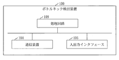
- the bottleneck detection device 100 includes a processing circuit 109.
- the processing circuit 109 is hardware that implements all or a part of the information extracting unit 111, the processing period determining unit 112, the used device determining unit 113, the used time calculating unit 114, the bottleneck detecting unit 115, and the sorting unit 116.
- the processing circuit 109 may be dedicated hardware or the processor 101 that executes a program stored in the memory 102.
- the processing circuit 109 is dedicated hardware, the processing circuit 109 is, for example, a single circuit, a composite circuit, a programmed processor, a parallel programmed processor, an ASIC, an FPGA, or a combination thereof.
- ASIC is an abbreviation for Application Specific Integrated Circuit
- FPGA is an abbreviation for Field Programmable Gate Array.
- the bottleneck detection device 100 may include a plurality of processing circuits replacing the processing circuit 109. The plurality of processing circuits share the role of the processing circuit 109.
- processing circuit 109 some functions may be realized by dedicated hardware, and the remaining functions may be realized by software or firmware.
- the processing circuit 109 can be realized by hardware, software, firmware, or a combination thereof.
- Embodiments are merely examples of preferred embodiments, and are not intended to limit the technical scope of the present invention. Embodiments may be implemented partially or in combination with other embodiments. The procedure described using the flowchart and the like may be appropriately changed.
- 100 bottleneck detection device 101 processor, 102 memory, 103 auxiliary storage device, 104 communication device, 105 input / output interface, 109 processing circuit, 111 information extraction unit, 112 processing period determination unit, 113 used device determination unit, 114 usage time Calculator, 115 ⁇ bottleneck detector, 116 # sorter, 120 # storage, 121 # production plan data, 122 # production procedure data, 123 # production equipment data, 124 # use period data, 125 # use time data, 126, 127 # bottleneck data.
Landscapes
- Engineering & Computer Science (AREA)
- General Engineering & Computer Science (AREA)
- Manufacturing & Machinery (AREA)
- Quality & Reliability (AREA)
- Physics & Mathematics (AREA)
- General Physics & Mathematics (AREA)
- Automation & Control Theory (AREA)
- Management, Administration, Business Operations System, And Electronic Commerce (AREA)
Abstract
Description
本発明は、変種変量生産においてボトルネックとなる装置を見つけるための技術に関するものである。 (4) The present invention relates to a technique for finding a device that becomes a bottleneck in a variety and variable production.
変種変量生産の製造現場において、受注によって生産機種が変わる。そのため、生産に必要な装置と装置を使用する時期とが一意に決まらず、生産においてボトルネックとなる装置を特定することが難しい。
このような課題を解決する方法として、装置負荷を判定し、処理能力を超える負荷がかかっている装置をボトルネックとなる装置として特定する方法がある。特許文献1は、そのような方法を提案している。
特許文献1に開示された方法では、装置が1日に処理できる枚数(処理可能枚数)と生産計画の達成のために1日に必要な処理枚数(必要処理枚数)とが計算される。そして、処理可能枚数が必要処理枚数に満たない装置がボトルネック装置と判定される。
At the manufacturing site for variant and variable production, production models change depending on orders. Therefore, it is difficult to uniquely determine a device necessary for production and a time when the device is used, and to identify a device that becomes a bottleneck in production.
As a method of solving such a problem, there is a method of determining a device load and specifying a device that has a load exceeding the processing capacity as a bottleneck device.
In the method disclosed in
近年の製造現場において変種変量生産の要望が強くなっており、1日に1つの装置が複数の機種を生産することが増えている。
このような変種変量生産において、装置が処理できる枚数は機種毎に異なる。つまり、同じ負荷でも機種毎に装置の処理枚数が異なることになる。このような場合、特許文献1のボトルネック判定方法では、機種毎の1日の必要処理枚数と機種毎の1日の処理可能枚数とが比較されることになる。しかし、1日の必要処理枚数と1日の処理可能枚数とを単純に比較したのでは、適切な判定ができない。
例えば、装置Aの1日の処理可能枚数が、機種1では100枚、機種2では200枚であると仮定する。また、1日の必要処理枚数が、機種1では80枚、機種2では50枚であると仮定する。この場合、機種毎に1日の処理可能枚数と1日の必要処理枚数とを単純に比較したのでは、一方の機種の生産によって、もう一方の機種の生産のための装置Aの処理能力の低減がボトルネック判定に反映されない。そのため、適切なボトルネック装置の判定は困難となる。さらに、機種の数が増加すればするほど、適切なボトルネックの判定は困難になる。
In recent years, there has been an increasing demand for variant and variable production at a manufacturing site, and it is increasing that one device produces a plurality of models per day.
In such variant production, the number of sheets that can be processed by the apparatus differs for each model. That is, even with the same load, the number of processed sheets of the apparatus differs for each model. In such a case, in the bottleneck determination method of
For example, it is assumed that the number of sheets that can be processed by the apparatus A per day is 100 in the
本発明は、対象期間に複数機種の生産が行われる変種変量生産においても、ボトルネックとなる装置を特定できるようにすることを目的とする。 The present invention has an object to specify a bottleneck device even in a variant and variable production in which a plurality of models are produced during a target period.
本発明のボトルネック検出装置は、
機種別の生産期限と、機種別の生産数と、機種別の生産手順における生産工程別の単位数あたりの処理時間とに基づいて、機種と生産工程との組別に、生産工程が行われる処理期間を決定する処理期間決定部と、
生産工程別に1つ以上の生産装置を示す生産装置データに基づいて、機種と生産工程との組別に、生産工程で使用される生産装置を使用装置として決定する使用装置決定部と、
機種と生産工程との組別の処理期間と、機種と生産工程との組別の使用装置とに基づいて、生産装置別に、対象期間における生産装置の使用時間を算出する使用時間算出部と、
前記対象期間における生産装置別の使用時間に基づいて、前記対象期間においてボトルネックとなる生産装置を見つけるボトルネック検出部とを備える。
The bottleneck detection device of the present invention,
A process in which a production process is performed for each set of a model and a production process based on the production deadline for each model, the number of productions for each model, and the processing time per unit for each production process in the production procedure for each model. A processing period determining unit for determining a period,
A use device determining unit that determines a production device used in the production process as a use device for each set of a model and a production process based on production device data indicating one or more production devices for each production process;
A processing time for each set of the model and the production process, and a use time calculation unit for calculating the use time of the production apparatus in the target period for each production device based on the used device for each set of the model and the production process,
A bottleneck detection unit that finds a production device that becomes a bottleneck in the target period based on the usage time of each production device in the target period.
本発明によれば、対象期間に複数機種の生産が行われる変種変量生産においても、ボトルネックとなる装置を特定することが可能となる。 According to the present invention, it is possible to specify a bottleneck device even in a variant and variable production in which a plurality of models are produced during a target period.
実施の形態および図面において、同じ要素または対応する要素には同じ符号を付している。説明した要素と同じ符号が付された要素の説明は適宜に省略または簡略化する。図中の矢印はデータの流れ又は処理の流れを主に示している。 に お い て In the embodiments and drawings, the same or corresponding elements are denoted by the same reference numerals. The description of the elements denoted by the same reference numerals as those described will be omitted or simplified as appropriate. The arrows in the figure mainly indicate the flow of data or the flow of processing.
実施の形態1.
変種変量生産においてボトルネックとなる装置を見つける形態について、図1から図12に基づいて説明する。
An embodiment in which a device that becomes a bottleneck in variant and variable production will be described with reference to FIGS.
***構成の説明***
図1に基づいて、ボトルネック検出装置100の構成を説明する。
ボトルネック検出装置100は、プロセッサ101とメモリ102と補助記憶装置103と通信装置104と入出力インタフェース105といったハードウェアを備えるコンピュータである。これらのハードウェアは、信号線を介して互いに接続されている。
*** Configuration description ***
The configuration of the
The
プロセッサ101は、演算処理を行うIC(Integrated Circuit)であり、他のハードウェアを制御する。例えば、プロセッサ101は、CPU(Central Processing Unit)、DSP(Digital Signal Processor)、またはGPU(Graphics Processing Unit)である。
メモリ102は揮発性の記憶装置である。メモリ102は、主記憶装置またはメインメモリとも呼ばれる。例えば、メモリ102はRAM(Random Access Memory)である。メモリ102に記憶されたデータは必要に応じて補助記憶装置103に保存される。
補助記憶装置103は不揮発性の記憶装置である。例えば、補助記憶装置103は、ROM(Read Only Memory)、HDD(Hard Disk Drive)、またはフラッシュメモリである。補助記憶装置103に記憶されたデータは必要に応じてメモリ102にロードされる。
通信装置104はレシーバ及びトランスミッタである。例えば、通信装置104は通信チップまたはNIC(Network Interface Card)である。
入出力インタフェース105は入力装置および出力装置が接続されるポートである。例えば、入出力インタフェース105はUSB端子であり、入力装置はキーボードおよびマウスであり、出力装置はディスプレイである。USBはUniversal Serial Busの略称である。
The
The
The
The
The input /
ボトルネック検出装置100は、情報抽出部111と処理期間決定部112と使用装置決定部113と使用時間算出部114とボトルネック検出部115といった要素を備える。これらの要素はソフトウェアで実現される。
The
補助記憶装置103には、情報抽出部111と処理期間決定部112と使用装置決定部113と使用時間算出部114とボトルネック検出部115としてコンピュータを機能させるためのボトルネック検出プログラムが記憶されている。ボトルネック検出プログラムは、メモリ102にロードされて、プロセッサ101によって実行される。
さらに、補助記憶装置103にはOS(Operating System)が記憶されている。OSの少なくとも一部は、メモリ102にロードされて、プロセッサ101によって実行される。
つまり、プロセッサ101は、OSを実行しながら、ボトルネック検出プログラムを実行する。
ボトルネック検出プログラムを実行して得られるデータは、メモリ102、補助記憶装置103、プロセッサ101内のレジスタ、または、プロセッサ101内のキャッシュメモリといった記憶装置に記憶される。
The
Further, the
That is, the
Data obtained by executing the bottleneck detection program is stored in a storage device such as the
補助記憶装置103は記憶部120として機能する。但し、他の記憶装置が、補助記憶装置103の代わりに、又は、補助記憶装置103と共に、記憶部120として機能してもよい。
The
ボトルネック検出装置100は、プロセッサ101を代替する複数のプロセッサを備えてもよい。複数のプロセッサは、プロセッサ101の役割を分担する。
(4) The
ボトルネック検出プログラムは、光ディスクまたはフラッシュメモリ等の不揮発性の記録媒体にコンピュータ読み取り可能に記録(格納)することができる。 The bottleneck detection program can be recorded (stored) in a computer-readable manner on a non-volatile recording medium such as an optical disk or a flash memory.
***動作の説明***
ボトルネック検出装置100の動作はボトルネック検出方法に相当する。また、ボトルネック検出方法の手順はボトルネック検出プログラムの手順に相当する。
*** Explanation of operation ***
The operation of the
図2に基づいて、ボトルネック検出方法の概要を説明する。
情報抽出部111は、生産計画データ121から、機種別の生産期限と機種別の生産数とを抽出する。さらに、情報抽出部111は、生産手順データ122から、機種別の1つ以上の生産工程における生産工程別の単位数あたりの処理時間を抽出する。
機種は、生産される物品の種類である。例えば、機種は半導体基板の種類である。
生産期限は、生産を完了すべき最終の時期である。例えば、生産期限は生産物の納期である。
生産数は、生産期限までに生産すべき生産物の数である。例えば、生産数は生産期限までに生産すべき半導体基板の枚数である。
生産物は、1つ以上の生産工程によって生産される。それぞれの生産工程では、単位数の物品を処理するために一定の時間(単位数あたりの処理時間)を要する。例えば、半導体基板の単位数は1枚である。
The outline of the bottleneck detection method will be described based on FIG.
The
The model is the type of article to be produced. For example, the model is the type of the semiconductor substrate.
The production deadline is the final time when production should be completed. For example, the production deadline is the delivery date of the product.
The production number is the number of products to be produced by the production deadline. For example, the production number is the number of semiconductor substrates to be produced by the production deadline.
The product is produced by one or more production processes. In each production process, a certain amount of time (processing time per unit) is required to process a unit number of articles. For example, the number of units of the semiconductor substrate is one.
生産計画データ121は、機種別の生産期限と機種別の生産数とを示すデータである。生産計画データ121は、記憶部120に予め記憶される。
The
生産手順データ122は、機種別の1つ以上の生産工程における生産工程別の単位数あたりの処理時間を示すデータである。生産手順データ122は、記憶部120に予め記憶される。
The
処理期間決定部112は、機種別の生産期限と、機種別の生産数と、機種別の生産手順における生産工程別の単位数あたりの処理時間とに基づいて、機種と生産工程との組別に処理期間を決定する。
生産手順は、行われる順番が決められた1つ以上の生産工程を含む。
処理期間は、当該機種のために当該生産工程が行われる期間である。
The processing
A production procedure includes one or more production steps in an order that is performed.
The processing period is a period during which the production process is performed for the model.
具体的には、処理期間決定部112は、機種別に、機種の生産数と生産工程別の単位数あたりの処理時間とに基づいて、生産工程別の処理時間を算出する。そして、処理期間決定部112は、機種別に、機種の生産期限と生産工程別の処理時間とに基づいて、生産工程別の処理期間を決定する。その際、処理期間決定部112は、最終の生産工程から逆順にそれぞれの生産工程の処理期間を決定する。
{Specifically, the processing
使用装置決定部113は、生産装置データ123に基づいて、機種と生産工程との組別に使用装置を決定する。
使用装置は、当該機種のために当該生産工程で使用される生産装置である。
The used
The used device is a production device used in the production process for the model.
生産装置データ123は、生産工程別に1つ以上の生産装置を示すデータである。生産装置データ123は、記憶部120に予め記憶される。
The
使用時間算出部114は、機種と生産工程との組別の処理期間と、機種と生産工程との組別の使用装置とに基づいて、生産装置別に、対象期間における生産装置の使用時間を算出する。
対象期間における生産装置の使用時間は、対象期間において生産装置が使用される時間である。
対象期間は、予め決められた期間である。例えば、1日の作業が3交代制で行われる。交代時刻は0時、8時および16時である。この場合、0時から8時までの期間と、8時から16時までの期間と、16時から24時までの期間とのそれぞれが対象期間となる。
The usage
The usage time of the production device in the target period is the time during which the production device is used in the target period.
The target period is a predetermined period. For example, one day's work is performed in three shifts. Alternation times are 0:00, 8:00 and 16:00. In this case, each of the period from 0:00 to 8:00, the period from 8:00 to 16:00, and the period from 16:00 to 24:00 are the target periods.
具体的には、使用時間算出部114は、機種と生産工程との組別の使用装置に基づいて、生産装置別に、機種と生産工程との組のうち生産装置と同じ使用装置に対応する組を選択する。そして、使用時間算出部114は、機種と生産工程との組別の処理期間に基づいて、生産装置別に、対象期間と選択した組の処理期間との重複時間の総和を算出する。算出される総和が対象期間における生産装置の使用時間である。
対象期間と処理期間との重複時間は、対象期間と処理期間とが重複する期間の時間である。
Specifically, the usage
The overlap time between the target period and the processing period is a period of time during which the target period and the processing period overlap.
具体的には、使用時間算出部114は、使用期間データ124に基づいて、生産装置別に対象期間における使用時間を算出する。
そして、使用時間算出部114は、使用時間データ125を出力する。
Specifically, the use
Then, the usage
使用期間データ124は、機種と生産工程との組別の処理期間と、機種と生産工程との組別の使用装置とを示すデータである。使用期間データ124は、処理期間決定部112と使用装置決定部113とによって生成され、記憶部120に記憶される。
The
使用時間データ125は、対象期間における生産装置別の使用時間を示すデータである。使用時間データ125は、使用期間データ124によって生成され、記憶部120に記憶される。
The use time data 125 is data indicating the use time of each production device in the target period. The usage time data 125 is generated by the
ボトルネック検出部115は、対象期間における生産装置別の使用時間に基づいて対象期間においてボトルネックとなる生産装置を見つける。
具体的には、ボトルネック検出部115は、使用時間データ125に基づいて、対象期間におけるボトルネックとなる生産装置を見つける。
そして、ボトルネック検出部115は、ボトルネックデータ126を出力する。
The
Specifically, the
Then,
ボトルネックデータ126は、対象期間においてボトルネックとなる1つ以上の生産装置を示すデータである。ボトルネックデータ126は、ボトルネック検出部115によって生成され、記憶部120に記憶される。
The bottleneck data 126 is data indicating one or more production devices that become a bottleneck in the target period. The bottleneck data 126 is generated by the
図3に基づいて、ボトルネック検出方法の詳細を説明する。
ステップS101において、情報抽出部111は、生産計画データ121から、未選択の機種を1つ選択する。
The details of the bottleneck detection method will be described with reference to FIG.
In step S101, the
図4に基づいて、生産計画データ121の具体例を説明する。
生産計画データ121は、機種別の生産計画情報を含む。
生産計画情報は、機種の生産計画を示す情報である。具体的には、生産計画情報は、機種と生産期限と生産数とを含む。
例えば、機種A001の生産計画情報は、機種A001の半導体基板を2018年3月16日の10時までに100枚生産する、という生産計画を示している。
A specific example of the
The
The production plan information is information indicating a production plan of a model. Specifically, the production plan information includes a model, a production deadline, and a production number.
For example, the production plan information of the model A001 indicates a production plan of producing 100 semiconductor substrates of the model A001 by 10:00 on March 16, 2018.
図3に戻り、ステップS102から説明を続ける。
ステップS102およびステップS110は、ステップS101で選択された機種のために実行される。ステップS101で選択された機種を対象機種という。
Returning to FIG. 3, the description will be continued from step S102.
Steps S102 and S110 are executed for the model selected in step S101. The model selected in step S101 is called a target model.
ステップS102において、情報抽出部111は、生産計画データ121と生産手順データ122とから、対象機種の機種生産情報を抽出する。
機種生産情報は、対象機種の生産計画情報と対象機種の生産手順情報とを含む。
In step S102, the
The model production information includes production plan information of the target model and production procedure information of the target model.
情報抽出部111は、対象機種の生産計画情報を生産計画データ121から抽出する。
生産計画情報は、図2で説明したように、機種と生産期限と生産数とを示す。
The
The production plan information indicates the model, the production deadline, and the number of products as described with reference to FIG.
情報抽出部111は、対象機種の生産手順情報を生産手順データ122から抽出する。
The
図5に基づいて、生産手順データ122の具体例を説明する。
生産手順データ122は、機種別の生産手順情報を含む。
生産手順情報は、生産工程別の生産工程情報を含む。
生産工程情報は、生産工程を示す情報である。具体的には、生産工程情報は、工程IDとインデックスと単位数あたりの処理時間とを含む。
工程IDは、生産工程を識別する識別子である。
インデックスは、生産工程の順番を示す番号である。
単位数あたりの処理時間は、生産工程において単位数の物品を処理するために要する時間である。
例えば、機種A001の生産手順情報は、工程Aの生産工程情報と工程Bの生産工程情報と工程Cの生産工程情報とを含む。工程Aの生産工程情報は、工程Aが最初の生産工程であること、および、機種A001の物品を工程Aで単位数だけ処理するために10分を要することを示す。工程Bの生産工程情報は、工程Bが工程Aの次の生産工程であること、および、機種A001の物品を工程Bで単位数だけ処理するために15分を要することを示す。工程Cの生産工程情報は、工程Cが工程Bの次の生産工程であること、工程Cが最終の生産工程であること、および、機種A001の物品を工程Cで単位数だけ処理するために5分を要することを示す。
A specific example of the
The
The production procedure information includes production process information for each production process.
The production process information is information indicating a production process. Specifically, the production process information includes a process ID, an index, and a processing time per unit.
The process ID is an identifier for identifying a production process.
The index is a number indicating the order of the production process.
The processing time per unit is the time required to process a unit number of articles in the production process.
For example, the production procedure information of the model A001 includes production process information of the process A, production process information of the process B, and production process information of the process C. The production process information of the process A indicates that the process A is the first production process, and that it takes 10 minutes to process the unit of the model A001 by the unit number in the process A. The production process information of the process B indicates that the process B is the next production process of the process A, and that it takes 15 minutes to process the unit of the model A001 by the unit number in the process B. The production process information of the process C includes information that the process C is the next production process after the process B, that the process C is the final production process, and that the articles of the model A001 are processed by the unit number in the process C. Indicates that it takes 5 minutes.
図3に戻り、ステップS110から説明を続ける。
ステップS110において、処理期間決定部112は、機種生産情報(生産計画情報および生産手順情報)に基づいて、対象機種と生産工程との組別に処理期間を決定する。
そして、処理期間決定部112は、対象機種と生産工程との組別の処理期間を使用期間データ124に登録する。
Returning to FIG. 3, the description will be continued from step S110.
In step S110, the processing
Then, the processing
また、使用装置決定部113は、生産装置データ123に基づいて、対象機種と生産工程との組別に使用装置を決定する。
そして、使用装置決定部113は、対象機種と生産工程との組別の使用装置を使用期間データ124に登録する。
Further, the used
Then, the used
図6に基づいて、生産装置データ123の具体例を説明する。
生産装置データ123は、生産工程別に1つ以上の生産装置を示す。
生産工程は、生産工程に対応付けられたいずれかの生産装置を用いて実行される。
具体的には、生産装置データ123は、生産工程別に工程IDと1つ以上の装置IDとを示す。
工程IDは、生産工程を識別する識別子である。
装置IDは、生産装置を識別する識別子である。
例えば、工程Aは、装置MA001または装置MA002を用いて実行される。
A specific example of the
The
The production process is executed using any one of the production devices associated with the production process.
Specifically, the
The process ID is an identifier for identifying a production process.
The device ID is an identifier for identifying a production device.
For example, the process A is performed using the device MA001 or the device MA002.
図7に基づいて、使用期間データ124の具体例を説明する。
使用期間データ124は、機種と生産工程との組別に処理期間と生産装置とを示す。
処理期間は、開始時刻と終了時刻とで示される。
開始時刻は、処理期間が始まる時刻である。
終了時刻は、処理期間が終わる時刻である。
例えば、機種A001の物品の生産において、工程Aは、装置MA001を用いて、2018年3月16日の9時9分から2018年3月16日の9時26分まで行われる。
A specific example of the
The
The processing period is indicated by a start time and an end time.
The start time is a time at which the processing period starts.
The end time is a time at which the processing period ends.
For example, in the production of an article of the model A001, the process A is performed from 9:09 on March 16, 2018 to 9:26 on March 16, 2018 using the device MA001.
図8に基づいて、決定処理(S110)の詳細を説明する。
ステップS111において、処理期間決定部112は、対象機種の生産手順情報から最終工程を選択し、選択した最終工程を対象工程に決定する。
最終工程は、生産手順における最終の生産工程である。具体的には、最終工程は、対象機種の生産手順情報において最大のインデックスに対応付けられた生産工程である。
対象工程は、ステップS112からステップS114までの処理の対象となる生産工程である。
The details of the determination process (S110) will be described based on FIG.
In step S111, the processing
The final step is the final production step in the production procedure. Specifically, the final process is a production process associated with the largest index in the production procedure information of the target model.
The target process is a production process to be processed in steps S112 to S114.
また、処理期間決定部112は、対象機種の生産計画情報から生産数を抽出し、抽出した生産数を処理数に決定する。
処理数は、対象工程で処理される物品の数である。
Further, the processing
The number of processes is the number of articles processed in the target process.
また、処理期間決定部112は、対象機種の生産計画情報から生産期限を抽出し、抽出した生産期限を基準時刻に決定する。
基準時刻は、対象工程の処理期間を決定するための基準となる時刻である。
Further, the processing
The reference time is a time serving as a reference for determining the processing period of the target process.
ステップS112において、使用装置決定部113は、生産装置データ123に基づいて、対象工程における使用装置を決定する。
In step S112, the used
まず、使用装置決定部113は、生産装置データ123から、対象工程に対応付けられた1つ以上の装置IDを抽出する。
そして、使用装置決定部113は、抽出した1つ以上の装置IDから1つの装置IDを選択する。選択される装置IDで識別される生産装置が対象工程における使用装置である。
First, the used
Then, the used
複数の生産装置が対象工程に対応付けられている場合、使用装置決定部113は、複数の生産装置の中で基準期間における使用時間が最も短い生産装置を選択する。基準期間は、基準時刻が含まれる期間である。選択される生産装置が対象工程における使用装置である。但し、使用装置決定部113は、対象工程における使用装置を別の方法で選択してもよい。
(4) When a plurality of production devices are associated with the target process, the used
そして、使用装置決定部113は、対象機種と対象工程との組の使用装置を使用期間データ124に登録する。
{Circle around (5)} The used
ステップS113において、処理期間決定部112は、生産手順情報から、対象工程の単位数あたりの処理時間を抽出する。ステップS113において、抽出される処理時間を単位処理時間という。
そして、処理期間決定部112は、処理数に単位処理時間をかけることによって、対象工程の処理時間を算出する。ステップS113において、算出される処理時間を工程処理時間という。
In step S113, the processing
Then, the processing
ステップS114において、処理期間決定部112は、基準時刻から工程処理時間前の時刻を算出する。算出される時刻が対象工程の開始時刻である。
さらに、処理期間決定部112は、基準時刻を対象工程の終了時刻に決定する。
そして、処理期間決定部112は、対象機種と対象工程との組の処理期間を使用期間データ124に登録する。
In step S114, the processing
Further, the processing
Then, the processing
ステップS115において、処理期間決定部112は、対象機種の生産手順情報を参照し、対象工程の前工程が存在するか判定する。
対象工程の前工程が存在する場合、処理はステップS116に進む。
対象工程の前工程が存在しない場合、つまり、対象工程が対象機種の生産手順における最初の生産工程である場合、決定処理(S110)は終了する。
In step S115, the processing
If there is a process before the target process, the process proceeds to step S116.
If there is no preceding process of the target process, that is, if the target process is the first production process in the production procedure of the target model, the determination processing (S110) ends.
ステップS116において、処理期間決定部112は、対象機種の生産手順情報から前工程を選択し、選択した前工程に対象工程を変更する。
さらに、処理期間決定部112は、基準時刻を前工程の次の工程(すなわち、変更前の対象工程)の開始時刻に変更する。つまり、処理期間決定部112は、ステップS114で算出した開始時刻に基準時刻を変更する。ステップS116において、前工程の次の工程を次工程という。
ステップS116の後、処理はステップS112に進む。
In step S116, the processing
Further, the processing
After step S116, the process proceeds to step S112.
図3に戻り、ステップS103から説明を続ける。
ステップS103において、情報抽出部111は、ステップS101で選択されていない機種が有るか判定する。ステップS103において、ステップS101で選択されていない機種を未選択機種という。
未選択機種が有る場合、処理はステップS101に進む。
未選択機種が無い場合、処理はステップS120に進む。
Returning to FIG. 3, the description will be continued from step S103.
In step S103, the
If there is an unselected model, the process proceeds to step S101.
If there is no unselected model, the process proceeds to step S120.
ステップS120において、使用時間算出部114は、使用期間データ124に基づいて、使用時間データ125を生成する。
In step S120, the usage
図9に基づいて、使用時間データ125の具体例を説明する。
使用時間データ125は、生産装置と対象期間との組別に対象期間における生産装置の使用時間を示す。
対象期間は、開始時刻と終了時刻とで示される。
開始時刻は、対象期間が始まる時刻である。
終了時刻は、対象期間が終わる時刻である。
使用時間は、生産装置が使用される時間である。
例えば、2018年3月16日の0時0分から8時0分までの対象期間における装置MA001の使用時間はt分である。
A specific example of the usage time data 125 will be described based on FIG.
The usage time data 125 indicates the usage time of the production device in the target period for each set of the production device and the target period.
The target period is indicated by a start time and an end time.
The start time is a time at which the target period starts.
The end time is a time at which the target period ends.
The usage time is the time during which the production device is used.
For example, the usage time of the device MA001 in the target period from 0:00 to 8:00 on March 16, 2018 is t minutes.
図10に基づいて、1つの対象期間に対する使用時間算出処理(S120)の詳細を説明する。図10の使用時間算出処理(S120)は、対象期間別に実行される。 {Details of the usage time calculation process (S120) for one target period will be described based on FIG. The use time calculation process (S120) in FIG. 10 is executed for each target period.
ステップS121において、使用時間算出部114は、未選択の生産装置を1つ選択する。
例えば、使用時間算出部114は、生産装置データ123から、未選択の生産装置を1つ選択する。
In step S121, the usage
For example, the usage
ステップS122からステップS125は、ステップS121で選択された生産装置のために実行される。ステップS101で選択された生産装置を対象装置という。 Steps S122 to S125 are executed for the production device selected in step S121. The production device selected in step S101 is called a target device.
ステップS122において、使用時間算出部114は、使用時間を初期化する。
具体的には、使用時間算出部114は、使用時間を0分にする。
In step S122, the usage
Specifically, the usage
ステップS123において、使用時間算出部114は、使用期間データ124を参照し、機種と生産工程との組から対象装置に対応する未選択の組を1つ選択する。
例えば、対象装置が装置MA001であると仮定する。この場合、使用時間算出部114は、図7の使用期間データ124から、機種A001と工程Aとの組を選択する。
In step S123, the usage
For example, assume that the target device is device MA001. In this case, the usage
ステップS124は、ステップS123で選択された組のために実行される。ステップS123で選択された組を選択組という。 Step S124 is executed for the set selected in step S123. The set selected in step S123 is called a selected set.
ステップS124において、使用時間算出部114は、使用期間データ124から選択組の処理期間を抽出する。
そして、使用時間算出部114は、対象期間と選択組の処理期間との重複時間を算出する。
In step S124, the usage
Then, the usage
例えば、対象装置が装置MA001であり、選択組が機種A001と工程Aとの組であると仮定する。この場合、使用時間算出部114は、図7の使用期間データ124から、「2018/3/16 09:09 ~ 2018/3/16 09:26」という処理期間を抽出する。例えば、対象期間が2018年3月16日の8時から2018年3月16日の16時までの期間であると仮定する。この場合、処理期間の全体が対象期間と重複する。そのため、使用時間算出部114は、処理期間の全体の時間である17分間を重複時間として算出する。
For example, it is assumed that the target device is the device MA001 and the selected set is a set of the model A001 and the process A. In this case, the usage
ステップS125において、使用時間算出部114は、使用時間に重複時間を加える。
例えば、使用時間が0分であり、重複時間が17分である場合、使用時間算出部114は、使用時間を17分に更新する。
In step S125, the use
For example, when the use time is 0 minute and the overlap time is 17 minutes, the use
ステップS126において、使用時間算出部114は、ステップS123で選択していない組が有るか判定する。ステップS126において、ステップS123で選択していない組を未選択組という。
未選択組が有る場合、処理はステップS123に進む。
未選択組が無い場合、処理はステップS127に進む。
In step S126, the usage
If there is an unselected set, the process proceeds to step S123.
If there is no unselected group, the process proceeds to step S127.
ステップS127において、使用時間算出部114は、対象装置と対象期間とに対応付けて使用時間を使用時間データ125に登録する。
In step S127, the usage
ステップS128において、使用時間算出部114は、ステップS121で選択されていない生産装置が有るか判定する。ステップS128において、ステップS121で選択されていない生産装置を未選択装置という。
未選択装置が有る場合、処理はステップS121に進む。
未選択装置が無い場合、使用時間算出処理(S120)は終了する。
In step S128, the usage
If there is an unselected device, the process proceeds to step S121.
If there is no unselected device, the use time calculation process (S120) ends.
図3に戻り、ステップS130を説明する。
ステップS130において、ボトルネック検出部115は、使用時間データ125に基づいて、ボトルネックデータ126を生成する。
そして、ボトルネック検出部115は、使用時間データ125を出力する。
Returning to FIG. 3, step S130 will be described.
In step S130, the
Then,
図11に基づいて、ボトルネックデータ126の具体例を説明する。
ボトルネックデータ126は、対象期間別に、ボトルネックとなる生産装置を示す。
ボトルネックとなる生産装置をボトルネック装置という。
例えば、2018年3月16日の0時0分から8時0分までの対象期間におけるボトルネック装置は装置MA001である。
A specific example of the bottleneck data 126 will be described with reference to FIG.
The bottleneck data 126 indicates a production device that becomes a bottleneck for each target period.
A production device that becomes a bottleneck is called a bottleneck device.
For example, the bottleneck device in the target period from 0:00 to 8:00 on March 16, 2018 is the device MA001.
図12に基づいて、1つの対象期間に対するボトルネック検出処理(S130)の詳細を説明する。図12のボトルネック検出処理(S130)は、対象期間別に実行される。 {Details of the bottleneck detection process (S130) for one target period will be described based on FIG. The bottleneck detection process (S130) in FIG. 12 is executed for each target period.
ステップS131において、ボトルネック検出部115は、未選択の生産装置を1つ選択する。
例えば、ボトルネック検出部115は、生産装置データ123から、未選択の生産装置を1つ選択する。
In step S131, the
For example, the
ステップS132からステップS134は、ステップS131で選択された生産装置のために実行される。ステップS131で選択された生産装置を対象装置という。 Steps S132 to S134 are executed for the production device selected in step S131. The production device selected in step S131 is called a target device.
ステップS132において、ボトルネック検出部115は、対象期間における対象装置の使用時間を使用時間データ125から抽出する。
例えば、対象装置が装置MA001である。また、対象期間が2018年3月16日の0時0分から8時0分までの期間である。この場合、ボトルネック検出部115は、図9の使用時間データ125から使用時間tを抽出する。
In step S132, the
For example, the target device is the device MA001. The target period is a period from 0:00 to 8:00 on March 16, 2018. In this case, the
ステップS133において、ボトルネック検出部115は、抽出した使用時間を基準時間と比較する。
基準時間は、閾値となる時間であり、予め決められる。
使用時間が基準時間を超えている場合、処理はステップS134に進む。
使用時間が基準時間以下である場合、処理はステップS135に進む。
In step S133, the
The reference time is a time serving as a threshold and is determined in advance.
If the use time exceeds the reference time, the process proceeds to step S134.
If the use time is equal to or shorter than the reference time, the process proceeds to step S135.
ステップS134において、ボトルネック検出部115は、対象期間に対応付けて対象装置をボトルネックデータ126に登録する。
例えば、対象期間が2018年3月16日の0時0分から8時0分までの期間である。また、対象期間における装置MA001の使用時間が基準時間を超えている。この場合、ボトルネック検出部115は、図11に示すように、対象期間に対応付けて装置MA001をボトルネックデータ126に登録する。
In step S134, the
For example, the target period is a period from 0:00 to 8:00 on March 16, 2018. Further, the usage time of the device MA001 in the target period has exceeded the reference time. In this case, as shown in FIG. 11, the
ステップS135において、ボトルネック検出部115は、未選択の生産装置が有るか判定する。ステップS135において、未選択の生産装置を未選択装置という。
未選択装置が有る場合、処理はステップS131に進む。
未選択装置が無い場合、ボトルネック検出処理(S130)は終了する。
In step S135, the
If there is an unselected device, the process proceeds to step S131.
If there is no unselected device, the bottleneck detection process (S130) ends.
***実施の形態1の効果***
実施の形態1により、機種別に、生産手順を構成する1つ以上の生産工程を最終工程から逆順に辿りながら、それぞれの生産工程の処理期間が決定することができる。また、生産装置別に、対象期間と生産装置に対応する生産工程別の処理時間との重複時間の総和を、対象期間における生産装置の使用時間として算出することができる。そして、生産装置別に対象期間における使用時間を基準時刻と比較することにより、対象期間においてボトルネックとなる生産装置を見つけることができる。
*** Effect of
According to the first embodiment, the processing period of each production process can be determined for each model while following one or more production processes constituting the production procedure in reverse order from the final process. In addition, for each production device, the total sum of the overlapping time of the target period and the processing time of each production process corresponding to the production device can be calculated as the usage time of the production device in the target period. Then, by comparing the usage time in the target period with the reference time for each production device, it is possible to find a production device that becomes a bottleneck in the target period.
実施の形態2.
生産工程別の歩留り率に基づいて生産工程別の処理数を算出する形態について、主に実施の形態1と異なる点を図13から図15に基づいて説明する。
A mode of calculating the number of processes for each production process based on the yield rate for each production process will be described mainly with reference to FIGS.
***構成の説明***
ボトルネック検出装置100の構成は、実施の形態1における構成と同じである。
*** Configuration description ***
The configuration of
***動作の説明***
図2に基づいて、ボトルネック検出方法の概要を説明する。
ボトルネック検出方法の概要は、実施の形態1における概要と以下の点で異なる。
生産手順データ122には、機種別の1つ以上の生産工程における生産工程別の単位数あたりの処理時間の他に、機種別の1つ以上の生産工程における生産工程別の歩留り率を示す。
情報抽出部111は、生産手順データ122から、機種別の1つ以上の生産工程における生産工程別の単位数あたりの処理時間の他に、機種別の1つ以上の生産工程における生産工程別の歩留り率を抽出する。
*** Explanation of operation ***
The outline of the bottleneck detection method will be described based on FIG.
The outline of the bottleneck detection method differs from the outline in the first embodiment in the following points.
The
From the
処理期間決定部112は、機種別の生産期限と、機種別の生産数と、機種別の1つ以上の生産工程における生産工程別の単位数あたりの処理時間と、機種別の1つ以上の生産工程における生産工程別の歩留り率とに基づいて、機種と生産工程との組別に処理期間を決定する。
具体的には、処理期間決定部112は、機種別に、生産数と生産工程別の歩留り率とに基づいて、生産工程別に処理数を算出する。また、処理期間決定部112は、機種別に、生産工程別の処理数と生産工程別の単位数あたりの処理時間とに基づいて、生産工程別の処理時間を算出する。そして、処理期間決定部112は、機種別に、生産期限と生産工程別の処理時間とに基づいて、生産工程別の処理時間を決定する。
The processing
Specifically, the processing
図13に基づいて、ボトルネック検出方法の詳細を説明する。
ステップS201において、情報抽出部111は、生産計画データ121から、未選択の機種を1つ選択する。選択された機種を対象機種という。
ステップS201は、実施の形態1におけるステップS101と同じである(図3参照)。
The details of the bottleneck detection method will be described with reference to FIG.
In step S201, the
Step S201 is the same as step S101 in the first embodiment (see FIG. 3).
ステップS202において、情報抽出部111は、生産計画データ121と生産手順データ122とから、対象機種の機種生産情報を抽出する。
機種生産情報は、対象機種の生産計画情報と対象機種の生産手順情報とを含む。
In step S202, the
The model production information includes production plan information of the target model and production procedure information of the target model.
情報抽出部111は、対象機種の生産計画情報を生産計画データ121から抽出する。
抽出される生産計画情報は、実施の形態1のステップS102における情報と同じである(図3参照)。
The
The extracted production plan information is the same as the information in step S102 of the first embodiment (see FIG. 3).
情報抽出部111は、対象機種の生産手順情報を生産手順データ122から抽出する。
The
図14に基づいて、生産手順データ122の具体例を説明する。
生産手順データ122は、機種別の生産手順情報を含む。
生産手順情報は、生産工程別の生産工程情報を含む。
生産工程情報は、生産工程を示す情報である。具体的には、生産工程情報は、工程IDとインデックスと単位数あたりの処理時間と歩留り率とを含む。
例えば、機種A001の生産工程情報は工程Bの生産工程情報を含む。工程Bの生産工程情報は工程Bの歩留り率が0.9であることを示す。これは、工程Bを通過した後の機種A001の処理数が、工程Bを通過する前の機種A001の処理数の0.9倍であることを意味する。
A specific example of the
The
The production procedure information includes production process information for each production process.
The production process information is information indicating a production process. Specifically, the production process information includes a process ID, an index, a processing time per unit number, and a yield rate.
For example, the production process information of the model A001 includes the production process information of the process B. The production process information of the process B indicates that the yield rate of the process B is 0.9. This means that the number of processes of the model A001 after passing through the process B is 0.9 times the number of processes of the model A001 before passing through the process B.
図13に戻り、ステップS210から説明を続ける。
ステップS210において、処理期間決定部112は、機種生産情報(生産計画情報および生産手順情報)に基づいて、対象機種と生産工程との組別に処理期間を決定する。
そして、処理期間決定部112は、対象機種と生産工程との組別の処理期間を使用期間データ124に登録する。
Returning to FIG. 13, the description will be continued from step S210.
In step S210, the processing
Then, the processing
また、使用装置決定部113は、生産装置データ123に基づいて、対象機種と生産工程との組別に使用装置を決定する。
そして、使用装置決定部113は、対象機種と生産工程との組別の使用装置を使用期間データ124に登録する。
Further, the used
Then, the used
ステップS210は、実施の形態1におけるステップS110に対応する。 Step S210 corresponds to Step S110 in the first embodiment.
図15に基づいて、決定処理(S210)の詳細を説明する。
ステップS211は、実施の形態1におけるステップS111に対応する。
ステップS211において、処理期間決定部112は、対象機種の生産手順情報から最終工程を選択し、選択した最終工程を対象工程に決定する。
また、処理期間決定部112は、対象機種の生産計画情報から生産数を抽出し、対象機種の生産手順情報から最終工程の歩留り率を抽出する。そして、処理期間決定部112は、抽出した生産数を抽出した歩留り率で割ることによって得られる値を処理数に決定する。
また、処理期間決定部112は、対象機種の生産計画情報から生産期限を抽出し、抽出した生産期限を基準時刻に決定する。
ステップS212からステップS216は、実施の形態1におけるステップS112からステップS116と同じである(図8参照)。
ステップS216の後、処理はステップS217に進む。
The details of the determination process (S210) will be described based on FIG.
Step S211 corresponds to step S111 in the first embodiment.
In step S211, the processing
Further, the processing
Further, the processing
Steps S212 to S216 are the same as steps S112 to S116 in the first embodiment (see FIG. 8).
After step S216, the process proceeds to step S217.
ステップS217において、処理期間決定部112は、対象機種の生産手順情報から、対象工程の歩留り率を抽出する。
処理期間決定部112は、次工程の処理数を対象工程の歩留り率で割ることによって、対象工程(前工程)の処理数を算出する。
ステップS217の後、処理はステップS212に進む。
In step S217, the processing
The processing
After step S217, the process proceeds to step S212.
図13に戻り、ステップS203から説明を続ける。
ステップS203において、情報抽出部111は、ステップS201で選択されていない機種が有るか判定する。ステップS203において、ステップS201で選択されていない機種を未選択機種という。
未選択機種が有る場合、処理はステップS201に進む。
未選択機種が無い場合、処理はステップS220に進む。
Returning to FIG. 13, the description will be continued from step S203.
In step S203, the
If there is an unselected model, the process proceeds to step S201.
If there is no unselected model, the process proceeds to step S220.
ステップS220において、使用時間算出部114は、使用期間データ124に基づいて、使用時間データ125を生成する。
ステップS220は、実施の形態1におけるステップS120と同じである(図3参照)。
In step S220, the
Step S220 is the same as step S120 in the first embodiment (see FIG. 3).
ステップS230において、ボトルネック検出部115は、使用時間データ125に基づいて、ボトルネックデータ126を生成する。
そして、ボトルネック検出部115は、使用時間データ125を出力する。
ステップS230は、実施の形態1におけるステップS130と同じである(図3参照)。
In step S230, the
Then,
Step S230 is the same as step S130 in the first embodiment (see FIG. 3).
***実施の形態2の効果***
歩留り率を考慮することによって、実際の数に近い処理数に基づいて生産工程別の処理期間を決定することができる。その結果、生産装置別の使用時間の精度が向上する。そして、ボトルネックとなる生産装置を見つける精度が向上する。
*** Effect of
By considering the yield, it is possible to determine the processing period for each production process based on the number of processes that is close to the actual number. As a result, the accuracy of the use time of each production device is improved. Then, the accuracy of finding a production device that becomes a bottleneck is improved.
実施の形態3.
利用者がボトルネック装置を確認し易くなる形態について、主に、実施の形態1と異なる点を図16から図18に基づいて説明する。
Embodiment 3 FIG.
A mode in which a user can easily check the bottleneck device will be described mainly with reference to FIGS.
***構成の説明***
図16に基づいて、ボトルネック検出装置100の構成を説明する。
ボトルネック検出装置100は、さらに、ソート部116という要素を備える。ソート部116は、ソフトウェアによって実現される。
ボトルネック検出プログラムは、さらに、ソート部116としてコンピュータを機能させる。
*** Configuration description ***
The configuration of the
The
The bottleneck detection program further causes the computer to function as the
***動作の説明***
図17に基づいて、ボトルネック検出方法の概要を説明する。
情報抽出部111と処理期間決定部112と使用装置決定部113と使用時間算出部114とボトルネック検出部115とについては、実施の形態1で説明した通りである(図2参照)。
*** Explanation of operation ***
The outline of the bottleneck detection method will be described based on FIG.
The
ソート部116は、ボトルネックデータ126に基づいて、ボトルネックデータ127を生成する。そして、ソート部116は、ボトルネックデータ127を出力する。
Sorting
ボトルネックデータ127は、対象期間別に、1つ以上のボトルネック装置を使用時間の多い順に示すデータである。ボトルネックデータ127は、ソート部116によって生成され、記憶部120に記憶される。
The bottleneck data 127 is data indicating one or more bottleneck devices in descending order of use time for each target period. The bottleneck data 127 is generated by the
図18に基づいて、ボトルネック検出方法の詳細を説明する。
ステップS301からステップS330は、実施の形態1におけるステップS101からステップS130と同じである(図3参照)。
ステップS330の後、処理はステップS140に進む。
The details of the bottleneck detection method will be described with reference to FIG.
Steps S301 to S330 are the same as steps S101 to S130 in the first embodiment (see FIG. 3).
After step S330, the process proceeds to step S140.
ステップS340において、ソート部116は、対象期間別に、ボトルネックデータ126に示される1つ以上のボトルネック装置を使用時間の多い順にソートする。ソート後のボトルネックデータ126がボトルネックデータ127である。
そして、ソート部116は、ボトルネックデータ127を出力する。例えば、ソート部116は、ボトルネックデータ127をディスプレイに表示する。
In step S340, the
Then, the
***実施の形態3の効果***
対象期間別に1つ以上のボトルネック装置を使用時間の多い順に並べ替えることができる。つまり、対象期間別に1つ以上のボトルネック装置を負荷が高い順に並べ替えることができる。その結果、利用者は、ボトルネックとなる度合いが高い生産装置を確認し易くなる。
*** Effect of Embodiment 3 ***
One or more bottleneck devices can be sorted in descending order of usage time for each target period. That is, one or more bottleneck devices can be sorted in descending order of load for each target period. As a result, it becomes easier for the user to identify a production device that has a high degree of bottleneck.
***他の構成***
実施の形態3において、実施の形態2が適用されてもよい。つまり、生産工程別の歩留り率に基づいて生産工程別の処理数が算出されてもよい。
*** Other configuration ***
In the third embodiment, the second embodiment may be applied. That is, the number of processes for each production process may be calculated based on the yield rate for each production process.
***実施の形態の補足***
図19に基づいて、ボトルネック検出装置100のハードウェア構成を説明する。
ボトルネック検出装置100は処理回路109を備える。
処理回路109は、情報抽出部111と処理期間決定部112と使用装置決定部113と使用時間算出部114とボトルネック検出部115とソート部116との全部または一部を実現するハードウェアである。
処理回路109は、専用のハードウェアであってもよいし、メモリ102に格納されるプログラムを実行するプロセッサ101であってもよい。
*** Supplement to the embodiment ***
The hardware configuration of the
The
The
The
処理回路109が専用のハードウェアである場合、処理回路109は、例えば、単一回路、複合回路、プログラム化したプロセッサ、並列プログラム化したプロセッサ、ASIC、FPGAまたはこれらの組み合わせである。
ASICはApplication Specific Integrated Circuitの略称であり、FPGAはField Programmable Gate Arrayの略称である。
ボトルネック検出装置100は、処理回路109を代替する複数の処理回路を備えてもよい。複数の処理回路は、処理回路109の役割を分担する。
When the
ASIC is an abbreviation for Application Specific Integrated Circuit, and FPGA is an abbreviation for Field Programmable Gate Array.
The
処理回路109において、一部の機能が専用のハードウェアで実現されて、残りの機能がソフトウェアまたはファームウェアで実現されてもよい。
In the
このように、処理回路109はハードウェア、ソフトウェア、ファームウェアまたはこれらの組み合わせで実現することができる。
As described above, the
実施の形態は、好ましい形態の例示であり、本発明の技術的範囲を制限することを意図するものではない。実施の形態は、部分的に実施してもよいし、他の形態と組み合わせて実施してもよい。フローチャート等を用いて説明した手順は、適宜に変更してもよい。 The embodiments are merely examples of preferred embodiments, and are not intended to limit the technical scope of the present invention. Embodiments may be implemented partially or in combination with other embodiments. The procedure described using the flowchart and the like may be appropriately changed.
100 ボトルネック検出装置、101 プロセッサ、102 メモリ、103 補助記憶装置、104 通信装置、105 入出力インタフェース、109 処理回路、111 情報抽出部、112 処理期間決定部、113 使用装置決定部、114 使用時間算出部、115 ボトルネック検出部、116 ソート部、120 記憶部、121 生産計画データ、122 生産手順データ、123 生産装置データ、124 使用期間データ、125 使用時間データ、126,127 ボトルネックデータ。 100 bottleneck detection device, 101 processor, 102 memory, 103 auxiliary storage device, 104 communication device, 105 input / output interface, 109 processing circuit, 111 information extraction unit, 112 processing period determination unit, 113 used device determination unit, 114 usage time Calculator, 115 {bottleneck detector, 116 # sorter, 120 # storage, 121 # production plan data, 122 # production procedure data, 123 # production equipment data, 124 # use period data, 125 # use time data, 126, 127 # bottleneck data.
Claims (7)
生産工程別に1つ以上の生産装置を示す生産装置データに基づいて、機種と生産工程との組別に、生産工程で使用される生産装置を使用装置として決定する使用装置決定部と、
機種と生産工程との組別の処理期間と、機種と生産工程との組別の使用装置とに基づいて、生産装置別に、対象期間における生産装置の使用時間を算出する使用時間算出部と、
前記対象期間における生産装置別の使用時間に基づいて、前記対象期間においてボトルネックとなる生産装置を見つけるボトルネック検出部と
を備えるボトルネック検出装置。 A process in which a production process is performed for each set of a model and a production process based on the production deadline for each model, the number of productions for each model, and the processing time per unit for each production process in the production procedure for each model. A processing period determining unit for determining a period,
A use device determining unit that determines a production device used in the production process as a use device for each set of a model and a production process based on production device data indicating one or more production devices for each production process;
A processing time for each set of the model and the production process, and a use time calculation unit for calculating the use time of the production apparatus in the target period for each production device based on the used device for each set of the model and the production process,
A bottleneck detection unit that detects a production device that becomes a bottleneck in the target period based on the usage time of each production device in the target period.
請求項1に記載のボトルネック検出装置。 The processing period determination unit calculates the processing time for each production process based on the number of models produced and the processing time per unit for each production process, for each model, and for each model, the production deadline of the model and the production process. The bottleneck detection device according to claim 1, wherein a processing period for each production process is determined based on the processing time.
請求項2に記載のボトルネック検出装置。 The processing period determining unit calculates the number of processes for each production process based on the number of products and the yield rate for each production process for each model, and for each model, the number of processes for each production process and the number of units for each production process. The bottleneck detection device according to claim 2, wherein the processing time for each production process is calculated based on the processing time.
請求項1から請求項3のいずれか1項に記載のボトルネック検出装置。 4. The bottleneck detection device according to claim 1, wherein the processing period determination unit determines a processing period of each production process in reverse order from a final production process. 5.
請求項1から請求項4のいずれか1項に記載のボトルネック検出装置。 The use time calculation unit selects a set corresponding to the same use device as the production device among the set of the model and the production process, for each production device, based on the use device for each combination of the model and the production process. The sum of the overlapping time of the target period and the processing period of the selected set is calculated as the use time of the production device in the target period, for each production device, based on the processing period of each pair of the production process and the production process. The bottleneck detection device according to claim 4.
前記ボトルネック検出部は、前記対象期間においてボトルネックとなる1つ以上の生産装置を1つ以上のボトルネック装置として見つけ、
前記ソート部は、前記1つ以上のボトルネック装置を使用時間の多い順に示すボトルネックデータを出力する
請求項1から請求項5のいずれか1項に記載のボトルネック検出装置。 The bottleneck detection device further includes a sorting unit,
The bottleneck detection unit finds one or more production devices that become bottlenecks in the target period as one or more bottleneck devices,
The bottleneck detection device according to any one of claims 1 to 5, wherein the sorting unit outputs bottleneck data indicating the one or more bottleneck devices in descending order of usage time.
生産工程別に1つ以上の生産装置を示す生産装置データに基づいて、機種と生産工程との組別に、生産工程で使用される生産装置を使用装置として決定する使用装置決定処理と、
機種と生産工程との組別の処理期間と、機種と生産工程との組別の使用装置とに基づいて、生産装置別に、対象期間における生産装置の使用時間を算出する使用時間算出処理と、
前記対象期間における生産装置別の使用時間に基づいて、前記対象期間においてボトルネックとなる生産装置を見つけるボトルネック検出処理
としてコンピュータを機能させるためのボトルネック検出プログラム。 A process in which a production process is performed for each set of a model and a production process based on the production deadline for each model, the number of productions for each model, and the processing time per unit for each production process in the production procedure for each model. Processing period determination processing for determining a period,
Based on production device data indicating one or more production devices for each production process, a use device determination process of determining a production device used in the production process as a use device for each set of model and production process;
Based on the processing period for each set of the model and the production process, and the used device for each set of the model and the production process, for each production device, a usage time calculation process for calculating the usage time of the production device in the target period,
A bottleneck detection program for causing a computer to function as bottleneck detection processing for finding a production device that becomes a bottleneck in the target period based on the usage time of each production device in the target period.
Priority Applications (1)
| Application Number | Priority Date | Filing Date | Title |
|---|---|---|---|
| PCT/JP2018/025065 WO2020008501A1 (en) | 2018-07-02 | 2018-07-02 | Bottleneck detecting device and bottleneck detecting program |
Applications Claiming Priority (1)
| Application Number | Priority Date | Filing Date | Title |
|---|---|---|---|
| PCT/JP2018/025065 WO2020008501A1 (en) | 2018-07-02 | 2018-07-02 | Bottleneck detecting device and bottleneck detecting program |
Publications (1)
| Publication Number | Publication Date |
|---|---|
| WO2020008501A1 true WO2020008501A1 (en) | 2020-01-09 |
Family
ID=69059503
Family Applications (1)
| Application Number | Title | Priority Date | Filing Date |
|---|---|---|---|
| PCT/JP2018/025065 Ceased WO2020008501A1 (en) | 2018-07-02 | 2018-07-02 | Bottleneck detecting device and bottleneck detecting program |
Country Status (1)
| Country | Link |
|---|---|
| WO (1) | WO2020008501A1 (en) |
Cited By (1)
| Publication number | Priority date | Publication date | Assignee | Title |
|---|---|---|---|---|
| CN116205023A (en) * | 2022-07-12 | 2023-06-02 | 上海奔曜科技有限公司 | Design method, device, equipment and storage medium of intelligent robot laboratory |
Citations (9)
| Publication number | Priority date | Publication date | Assignee | Title |
|---|---|---|---|---|
| JPH05101073A (en) * | 1991-10-04 | 1993-04-23 | Toppan Printing Co Ltd | Production schedule planning device |
| JPH10289274A (en) * | 1997-04-16 | 1998-10-27 | Yokogawa Electric Corp | Scheduling system |
| JPH11333674A (en) * | 1998-05-26 | 1999-12-07 | Matsushita Electric Works Ltd | Production plan forming method for multistage job shop type production |
| JP2000084801A (en) * | 1998-09-14 | 2000-03-28 | Mitsubishi Electric Corp | Method and apparatus for controlling the flow of a circulation type manufacturing process |
| JP2003141214A (en) * | 2001-10-30 | 2003-05-16 | Mitsubishi Electric Corp | Production plan creation system, production plan creation method, and program for causing computer to execute production plan creation |
| JP2004145436A (en) * | 2002-10-22 | 2004-05-20 | Matsushita Electric Ind Co Ltd | Production plan preparation method and apparatus |
| JP2006039852A (en) * | 2004-07-26 | 2006-02-09 | Toshiba Corp | Device priority order adjustment system, device priority order adjustment method, and program |
| JP2010165283A (en) * | 2009-01-19 | 2010-07-29 | Kobe Steel Ltd | Equipment load plan preparation device, method therefor, program therefor and recording medium |
| JP2015087803A (en) * | 2013-10-28 | 2015-05-07 | 株式会社日立製作所 | Component facility allocation device, component facility allocation method, and program |
-
2018
- 2018-07-02 WO PCT/JP2018/025065 patent/WO2020008501A1/en not_active Ceased
Patent Citations (9)
| Publication number | Priority date | Publication date | Assignee | Title |
|---|---|---|---|---|
| JPH05101073A (en) * | 1991-10-04 | 1993-04-23 | Toppan Printing Co Ltd | Production schedule planning device |
| JPH10289274A (en) * | 1997-04-16 | 1998-10-27 | Yokogawa Electric Corp | Scheduling system |
| JPH11333674A (en) * | 1998-05-26 | 1999-12-07 | Matsushita Electric Works Ltd | Production plan forming method for multistage job shop type production |
| JP2000084801A (en) * | 1998-09-14 | 2000-03-28 | Mitsubishi Electric Corp | Method and apparatus for controlling the flow of a circulation type manufacturing process |
| JP2003141214A (en) * | 2001-10-30 | 2003-05-16 | Mitsubishi Electric Corp | Production plan creation system, production plan creation method, and program for causing computer to execute production plan creation |
| JP2004145436A (en) * | 2002-10-22 | 2004-05-20 | Matsushita Electric Ind Co Ltd | Production plan preparation method and apparatus |
| JP2006039852A (en) * | 2004-07-26 | 2006-02-09 | Toshiba Corp | Device priority order adjustment system, device priority order adjustment method, and program |
| JP2010165283A (en) * | 2009-01-19 | 2010-07-29 | Kobe Steel Ltd | Equipment load plan preparation device, method therefor, program therefor and recording medium |
| JP2015087803A (en) * | 2013-10-28 | 2015-05-07 | 株式会社日立製作所 | Component facility allocation device, component facility allocation method, and program |
Cited By (2)
| Publication number | Priority date | Publication date | Assignee | Title |
|---|---|---|---|---|
| CN116205023A (en) * | 2022-07-12 | 2023-06-02 | 上海奔曜科技有限公司 | Design method, device, equipment and storage medium of intelligent robot laboratory |
| CN116205023B (en) * | 2022-07-12 | 2024-03-08 | 上海奔曜科技有限公司 | Design method, device, equipment and storage medium of intelligent robot laboratory |
Similar Documents
| Publication | Publication Date | Title |
|---|---|---|
| US10877962B2 (en) | Deferred update of database hashcode in blockchain | |
| CN113383364B (en) | Method, electronic equipment, system and medium for selecting nodes of verifier | |
| US10212844B2 (en) | System and method for improving fan life in an information handling system | |
| CN107133856B (en) | Risk order control method and device | |
| CN115033453B (en) | Abnormality detection method, device, equipment, storage medium and program | |
| JP2019057276A5 (en) | ||
| CN110427259A (en) | A task processing method and device | |
| WO2024183510A1 (en) | Test case selection method and apparatus, device, and storage medium | |
| US11042457B2 (en) | Application updates | |
| CN108228442A (en) | A kind of detection method and device of abnormal nodes | |
| CN111091287A (en) | Risk object identification method, device and computer equipment | |
| WO2020008501A1 (en) | Bottleneck detecting device and bottleneck detecting program | |
| CN104636279A (en) | Address assignment identification method and address assignment identification circuit | |
| CN108932241B (en) | Log data statistical method, device and node | |
| CN105824934A (en) | Method and device for finding slow nodes in distributive ETL | |
| CN110083775B (en) | Configuration method and configuration device for recommended resources | |
| CN108595685B (en) | A data processing method and device | |
| CN107656927B (en) | A feature selection method and device | |
| CN114048231A (en) | Data processing method, device and computer program product | |
| CN107516114B (en) | A time series processing method and device | |
| WO2018207322A1 (en) | Data collection device and data collection program | |
| CN118335267A (en) | A method and device for optimizing rubber molding strength based on chemical surface treatment | |
| CN109690584A (en) | Information processing device, information processing method, and information processing program | |
| JP6571027B2 (en) | Data storage device and data storage program | |
| US8271981B2 (en) | Detecting an extraordinary behavior |
Legal Events
| Date | Code | Title | Description |
|---|---|---|---|
| 121 | Ep: the epo has been informed by wipo that ep was designated in this application |
Ref document number: 18925483 Country of ref document: EP Kind code of ref document: A1 |
|
| NENP | Non-entry into the national phase |
Ref country code: DE |
|
| 122 | Ep: pct application non-entry in european phase |
Ref document number: 18925483 Country of ref document: EP Kind code of ref document: A1 |
|
| NENP | Non-entry into the national phase |
Ref country code: JP |