WO2020008501A1 - Dispositif de détection de goulot d'étranglement et procédé de détection de goulot d'étranglement - Google Patents
Dispositif de détection de goulot d'étranglement et procédé de détection de goulot d'étranglement Download PDFInfo
- Publication number
- WO2020008501A1 WO2020008501A1 PCT/JP2018/025065 JP2018025065W WO2020008501A1 WO 2020008501 A1 WO2020008501 A1 WO 2020008501A1 JP 2018025065 W JP2018025065 W JP 2018025065W WO 2020008501 A1 WO2020008501 A1 WO 2020008501A1
- Authority
- WO
- WIPO (PCT)
- Prior art keywords
- production
- model
- production process
- period
- bottleneck
- Prior art date
- Legal status (The legal status is an assumption and is not a legal conclusion. Google has not performed a legal analysis and makes no representation as to the accuracy of the status listed.)
- Ceased
Links
Images






Classifications
-
- G—PHYSICS
- G05—CONTROLLING; REGULATING
- G05B—CONTROL OR REGULATING SYSTEMS IN GENERAL; FUNCTIONAL ELEMENTS OF SUCH SYSTEMS; MONITORING OR TESTING ARRANGEMENTS FOR SUCH SYSTEMS OR ELEMENTS
- G05B19/00—Program-control systems
- G05B19/02—Program-control systems electric
- G05B19/418—Total factory control, i.e. centrally controlling a plurality of machines, e.g. direct or distributed numerical control [DNC], flexible manufacturing systems [FMS], integrated manufacturing systems [IMS] or computer integrated manufacturing [CIM]
-
- Y—GENERAL TAGGING OF NEW TECHNOLOGICAL DEVELOPMENTS; GENERAL TAGGING OF CROSS-SECTIONAL TECHNOLOGIES SPANNING OVER SEVERAL SECTIONS OF THE IPC; TECHNICAL SUBJECTS COVERED BY FORMER USPC CROSS-REFERENCE ART COLLECTIONS [XRACs] AND DIGESTS
- Y02—TECHNOLOGIES OR APPLICATIONS FOR MITIGATION OR ADAPTATION AGAINST CLIMATE CHANGE
- Y02P—CLIMATE CHANGE MITIGATION TECHNOLOGIES IN THE PRODUCTION OR PROCESSING OF GOODS
- Y02P90/00—Enabling technologies with a potential contribution to greenhouse gas [GHG] emissions mitigation
- Y02P90/02—Total factory control, e.g. smart factories, flexible manufacturing systems [FMS] or integrated manufacturing systems [IMS]
Definitions
- the present invention relates to a technique for finding a device that becomes a bottleneck in a variety and variable production.
- Patent Document 1 proposes such a method.
- the number of sheets that can be processed by the apparatus per day (the number of sheets that can be processed) and the number of sheets that can be processed per day to achieve a production plan (the number of processed sheets) are calculated. Then, a device whose number of processable sheets is less than the required number of processed sheets is determined as a bottleneck device.
- the required number of processed sheets per day is 80 for model 1 and 50 for model 2.
- simply comparing the number of sheets that can be processed in one day with the number of sheets that can be processed in one day for each model indicates that the production of one model will reduce the processing capacity of the apparatus A for the production of the other model. The reduction is not reflected in the bottleneck determination. Therefore, it is difficult to determine an appropriate bottleneck device. Further, as the number of models increases, it becomes more difficult to determine an appropriate bottleneck.
- the present invention has an object to specify a bottleneck device even in a variant and variable production in which a plurality of models are produced during a target period.
- the bottleneck detection device of the present invention A process in which a production process is performed for each set of a model and a production process based on the production deadline for each model, the number of productions for each model, and the processing time per unit for each production process in the production procedure for each model.
- a processing period determining unit for determining a period A use device determining unit that determines a production device used in the production process as a use device for each set of a model and a production process based on production device data indicating one or more production devices for each production process; A processing time for each set of the model and the production process, and a use time calculation unit for calculating the use time of the production apparatus in the target period for each production device based on the used device for each set of the model and the production process, A bottleneck detection unit that finds a production device that becomes a bottleneck in the target period based on the usage time of each production device in the target period.
- the present invention it is possible to specify a bottleneck device even in a variant and variable production in which a plurality of models are produced during a target period.
- FIG. 2 is a configuration diagram of a bottleneck detection device 100 according to the first embodiment.
- FIG. 2 is a schematic diagram of a bottleneck detection method according to the first embodiment.
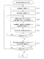
- 5 is a flowchart of a bottleneck detection method according to the first embodiment.
- FIG. 4 is a diagram showing a specific example of production plan data 121 according to the first embodiment.
- FIG. 4 is a diagram showing a specific example of production procedure data 122 according to the first embodiment.
- FIG. 4 is a diagram showing a specific example of production device data 123 according to the first embodiment.
- FIG. 4 is a diagram showing a specific example of usage period data 124 according to the first embodiment.
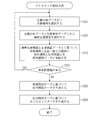
- 9 is a flowchart of a determination process (S110) according to the first embodiment.
- FIG. 110 determination process
- FIG. 4 is a diagram showing a specific example of usage time data 125 according to the first embodiment.
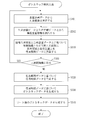
- 9 is a flowchart of a usage time calculation process (S120) according to the first embodiment.
- FIG. 4 is a diagram showing a specific example of bottleneck data 126 according to the first embodiment.
- 9 is a flowchart of a bottleneck detection process (S130) according to the first embodiment.
- 9 is a flowchart of a bottleneck detection method according to the second embodiment.
- FIG. 14 is a diagram showing a specific example of production procedure data 122 according to the second embodiment.
- 13 is a flowchart of a determination process (S210) according to the second embodiment.
- FIG. 9 is a configuration diagram of a bottleneck detection device 100 according to a third embodiment.
- FIG. 11 is a schematic diagram of a bottleneck detection method according to the third embodiment.
- 15 is a flowchart of a bottleneck detection method according to the third embodiment.
- FIG. 2 is a hardware configuration
- Embodiment 1 FIG. An embodiment in which a device that becomes a bottleneck in variant and variable production will be described with reference to FIGS.
- the configuration of the bottleneck detection device 100 is a computer including hardware such as a processor 101, a memory 102, an auxiliary storage device 103, a communication device 104, and an input / output interface 105. These hardwares are connected to each other via signal lines.
- the processor 101 is an IC (Integrated Circuit) that performs arithmetic processing, and controls other hardware.
- the processor 101 is a CPU (Central Processing Unit), a DSP (Digital Signal Processor), or a GPU (Graphics Processing Unit).
- the memory 102 is a volatile storage device.
- the memory 102 is also called a main storage device or a main memory.
- the memory 102 is a RAM (Random Access Memory).
- the data stored in the memory 102 is stored in the auxiliary storage device 103 as needed.
- the auxiliary storage device 103 is a nonvolatile storage device.
- the auxiliary storage device 103 is a ROM (Read Only Memory), a HDD (Hard Disk Drive), or a flash memory.
- the data stored in the auxiliary storage device 103 is loaded into the memory 102 as needed.
- the communication device 104 is a receiver and a transmitter.
- the communication device 104 is a communication chip or a NIC (Network Interface Card).
- the input / output interface 105 is a port to which an input device and an output device are connected.
- the input / output interface 105 is a USB terminal, the input device is a keyboard and a mouse, and the output device is a display.
- USB is an abbreviation for Universal Serial Bus.
- the bottleneck detection device 100 includes elements such as an information extraction unit 111, a processing period determination unit 112, a use device determination unit 113, a use time calculation unit 114, and a bottleneck detection unit 115. These elements are realized by software.
- the auxiliary storage device 103 stores a bottleneck detection program for causing a computer to function as the information extraction unit 111, the processing period determination unit 112, the use device determination unit 113, the use time calculation unit 114, and the bottleneck detection unit 115. I have.
- the bottleneck detection program is loaded into the memory 102 and executed by the processor 101.
- the auxiliary storage device 103 stores an OS (Operating System). At least a part of the OS is loaded into the memory 102 and executed by the processor 101. That is, the processor 101 executes the bottleneck detection program while executing the OS.
- Data obtained by executing the bottleneck detection program is stored in a storage device such as the memory 102, the auxiliary storage device 103, a register in the processor 101, or a cache memory in the processor 101.
- the auxiliary storage device 103 functions as the storage unit 120. However, another storage device may function as the storage unit 120 instead of the auxiliary storage device 103 or together with the auxiliary storage device 103.
- the bottleneck detection device 100 may include a plurality of processors instead of the processor 101.
- the plurality of processors share the role of the processor 101.
- the bottleneck detection program can be recorded (stored) in a computer-readable manner on a non-volatile recording medium such as an optical disk or a flash memory.
- the operation of the bottleneck detection device 100 corresponds to a bottleneck detection method.
- the procedure of the bottleneck detection method corresponds to the procedure of the bottleneck detection program.
- the information extraction unit 111 extracts, from the production plan data 121, a production deadline and a production number for each model. Further, the information extraction unit 111 extracts, from the production procedure data 122, a processing time per unit number in one or more production processes for each model for each production process.
- the model is the type of article to be produced.
- the model is the type of the semiconductor substrate.
- the production deadline is the final time when production should be completed.
- the production deadline is the delivery date of the product.
- the production number is the number of products to be produced by the production deadline.
- the production number is the number of semiconductor substrates to be produced by the production deadline.
- the product is produced by one or more production processes. In each production process, a certain amount of time (processing time per unit) is required to process a unit number of articles. For example, the number of units of the semiconductor substrate is one.
- the production plan data 121 is data indicating a production deadline and a production number for each model.
- the production plan data 121 is stored in the storage unit 120 in advance.
- the production procedure data 122 is data indicating the processing time per unit number in one or more production processes for each model.
- the production procedure data 122 is stored in the storage unit 120 in advance.
- the processing period determination unit 112 separates the model and the production process based on the production deadline for each model, the number of productions for each model, and the processing time per unit for each production process in the production procedure for each model. Determine the processing period.
- a production procedure includes one or more production steps in an order that is performed.
- the processing period is a period during which the production process is performed for the model.
- the processing period determination unit 112 calculates the processing time for each production process, based on the number of models produced and the processing time per unit for each production process. Then, the processing period determination unit 112 determines the processing period for each production process based on the production deadline of the model and the processing time for each production process for each model. At that time, the processing period determination unit 112 determines the processing period of each production process in reverse order from the last production process.
- the used device determining unit 113 determines the used device for each set of the model and the production process based on the production device data 123.
- the used device is a production device used in the production process for the model.
- the production device data 123 is data indicating one or more production devices for each production process.
- the production device data 123 is stored in the storage unit 120 in advance.
- the usage time calculation unit 114 calculates the usage time of the production device in the target period for each production device based on the processing period for each pair of the model and the production process and the usage device for each combination of the model and the production process. I do.
- the usage time of the production device in the target period is the time during which the production device is used in the target period.
- the target period is a predetermined period. For example, one day's work is performed in three shifts. Alternation times are 0:00, 8:00 and 16:00. In this case, each of the period from 0:00 to 8:00, the period from 8:00 to 16:00, and the period from 16:00 to 24:00 are the target periods.
- the usage time calculation unit 114 determines, for each production device, a group corresponding to the same usage device as the production device among the pair of the model and the production process based on the usage device for each pair of the model and the production process. Select Then, the usage time calculation unit 114 calculates, for each production apparatus, the total sum of the overlapping times of the target period and the processing period of the selected group, based on the processing period for each pair of the model and the production process. The calculated sum is the usage time of the production device in the target period.
- the overlap time between the target period and the processing period is a period of time during which the target period and the processing period overlap.
- the use time calculation unit 114 calculates the use time in the target period for each production device based on the use period data 124. Then, the usage time calculation unit 114 outputs the usage time data 125.
- the use period data 124 is data indicating a processing period for each set of a model and a production process, and a used apparatus for each set of a model and a production process.
- the usage period data 124 is generated by the processing period determination unit 112 and the used device determination unit 113, and is stored in the storage unit 120.
- the use time data 125 is data indicating the use time of each production device in the target period.
- the usage time data 125 is generated by the usage period data 124 and stored in the storage unit 120.
- the bottleneck detection unit 115 finds a production device that becomes a bottleneck in the target period based on the usage time of each production device in the target period. Specifically, the bottleneck detection unit 115 finds a production device that becomes a bottleneck in the target period based on the usage time data 125. Then, bottleneck detecting section 115 outputs bottleneck data 126.
- the bottleneck data 126 is data indicating one or more production devices that become a bottleneck in the target period.
- the bottleneck data 126 is generated by the bottleneck detection unit 115 and stored in the storage unit 120.
- step S101 the information extraction unit 111 selects one unselected model from the production plan data 121.
- the production plan data 121 includes production plan information for each model.
- the production plan information is information indicating a production plan of a model.
- the production plan information includes a model, a production deadline, and a production number.
- the production plan information of the model A001 indicates a production plan of producing 100 semiconductor substrates of the model A001 by 10:00 on March 16, 2018.
- Steps S102 and S110 are executed for the model selected in step S101.
- the model selected in step S101 is called a target model.
- step S102 the information extracting unit 111 extracts model production information of the target model from the production plan data 121 and the production procedure data 122.
- the model production information includes production plan information of the target model and production procedure information of the target model.
- the information extracting unit 111 extracts the production plan information of the target model from the production plan data 121.
- the production plan information indicates the model, the production deadline, and the number of products as described with reference to FIG.
- the information extraction unit 111 extracts the production procedure information of the target model from the production procedure data 122.
- the production procedure data 122 includes production procedure information for each model.
- the production procedure information includes production process information for each production process.
- the production process information is information indicating a production process.
- the production process information includes a process ID, an index, and a processing time per unit.
- the process ID is an identifier for identifying a production process.
- the index is a number indicating the order of the production process.
- the processing time per unit is the time required to process a unit number of articles in the production process.
- the production procedure information of the model A001 includes production process information of the process A, production process information of the process B, and production process information of the process C.
- the production process information of the process A indicates that the process A is the first production process, and that it takes 10 minutes to process the unit of the model A001 by the unit number in the process A.
- the production process information of the process B indicates that the process B is the next production process of the process A, and that it takes 15 minutes to process the unit of the model A001 by the unit number in the process B.
- the production process information of the process C includes information that the process C is the next production process after the process B, that the process C is the final production process, and that the articles of the model A001 are processed by the unit number in the process C. Indicates that it takes 5 minutes.
- step S110 the processing period determination unit 112 determines a processing period for each set of the target model and the production process based on the model production information (production plan information and production procedure information). Then, the processing period determining unit 112 registers the processing period for each set of the target model and the production process in the usage period data 124.
- the used device determining unit 113 determines the used device for each set of the target model and the production process based on the production device data 123. Then, the used device determining unit 113 registers the used device for each set of the target model and the production process in the usage period data 124.
- the production device data 123 indicates one or more production devices for each production process.
- the production process is executed using any one of the production devices associated with the production process.
- the production device data 123 indicates a process ID and one or more device IDs for each production process.
- the process ID is an identifier for identifying a production process.
- the device ID is an identifier for identifying a production device.
- the process A is performed using the device MA001 or the device MA002.
- the use period data 124 indicates a processing period and a production device for each set of a model and a production process.
- the processing period is indicated by a start time and an end time.
- the start time is a time at which the processing period starts.
- the end time is a time at which the processing period ends. For example, in the production of an article of the model A001, the process A is performed from 9:09 on March 16, 2018 to 9:26 on March 16, 2018 using the device MA001.
- step S111 the processing period determination unit 112 selects the final process from the production procedure information of the target model, and determines the selected final process as the target process.
- the final step is the final production step in the production procedure.
- the final process is a production process associated with the largest index in the production procedure information of the target model.
- the target process is a production process to be processed in steps S112 to S114.
- the processing period determination unit 112 extracts the number of productions from the production plan information of the target model, and determines the extracted number of productions as the number of processes.
- the number of processes is the number of articles processed in the target process.
- the processing period determining unit 112 extracts a production deadline from the production plan information of the target model, and determines the extracted production deadline as a reference time.
- the reference time is a time serving as a reference for determining the processing period of the target process.
- step S112 the used device determining unit 113 determines the used device in the target process based on the production device data 123.
- the used device determination unit 113 extracts one or more device IDs associated with the target process from the production device data 123. Then, the used device determining unit 113 selects one device ID from the extracted one or more device IDs. The production device identified by the selected device ID is the device used in the target process.
- the used device determination unit 113 selects a production device having the shortest usage time in the reference period among the plurality of production devices.
- the reference period is a period including the reference time.
- the selected production equipment is the equipment used in the target process.
- the used device determining unit 113 may select a used device in the target process by another method.
- the used device determination unit 113 registers the used device of the set of the target model and the target process in the usage period data 124.
- step S113 the processing period determination unit 112 extracts the processing time per unit of the target process from the production procedure information.
- the processing time extracted in step S113 is called a unit processing time.
- the processing period determination unit 112 calculates the processing time of the target process by multiplying the number of processes by the unit processing time.
- the processing time calculated in step S113 is called a process processing time.
- step S114 the processing period determination unit 112 calculates a time before the process processing time from the reference time.
- the calculated time is the start time of the target process. Further, the processing period determination unit 112 determines the reference time as the end time of the target process. Then, the processing period determination unit 112 registers the processing period of the set of the target model and the target process in the usage period data 124.
- step S115 the processing period determination unit 112 refers to the production procedure information of the target model and determines whether there is a process preceding the target process. If there is a process before the target process, the process proceeds to step S116. If there is no preceding process of the target process, that is, if the target process is the first production process in the production procedure of the target model, the determination processing (S110) ends.
- step S116 the processing period determination unit 112 selects a previous process from the production procedure information of the target model, and changes the target process to the selected previous process. Further, the processing period determining unit 112 changes the reference time to the start time of the next process (that is, the target process before the change) of the previous process. That is, the processing period determination unit 112 changes the reference time to the start time calculated in step S114. In step S116, a step next to the previous step is referred to as a next step. After step S116, the process proceeds to step S112.
- step S103 the information extraction unit 111 determines whether there is any model that has not been selected in step S101.
- step S103 a model not selected in step S101 is called an unselected model. If there is an unselected model, the process proceeds to step S101. If there is no unselected model, the process proceeds to step S120.
- step S120 the usage time calculation unit 114 generates usage time data 125 based on the usage period data 124.
- the usage time data 125 indicates the usage time of the production device in the target period for each set of the production device and the target period.
- the target period is indicated by a start time and an end time.
- the start time is a time at which the target period starts.
- the end time is a time at which the target period ends.
- the usage time is the time during which the production device is used. For example, the usage time of the device MA001 in the target period from 0:00 to 8:00 on March 16, 2018 is t minutes.
- step S121 the usage time calculation unit 114 selects one unselected production device. For example, the usage time calculation unit 114 selects one unselected production device from the production device data 123.
- Steps S122 to S125 are executed for the production device selected in step S121.
- the production device selected in step S101 is called a target device.
- step S122 the usage time calculation unit 114 initializes the usage time. Specifically, the usage time calculation unit 114 sets the usage time to 0 minutes.
- step S123 the usage time calculation unit 114 refers to the usage period data 124 and selects one unselected set corresponding to the target device from the set of the model and the production process. For example, assume that the target device is device MA001. In this case, the usage time calculation unit 114 selects a set of the model A001 and the process A from the usage period data 124 of FIG.
- Step S124 is executed for the set selected in step S123.
- the set selected in step S123 is called a selected set.
- step S124 the usage time calculation unit 114 extracts the processing period of the selected set from the usage period data 124. Then, the usage time calculation unit 114 calculates the overlap time between the target period and the processing period of the selected set.
- the target device is the device MA001 and the selected set is a set of the model A001 and the process A.
- the usage time calculation unit 114 extracts a processing period “2018/3/16 ⁇ 09:09 ⁇ to ⁇ 2018/3/16 ⁇ 09:26” from the usage period data 124 of FIG.
- the target period is a period from 8:00 on March 16, 2018 to 16:00 on March 16, 2018.
- the entire processing period overlaps with the target period. Therefore, the usage time calculation unit 114 calculates 17 minutes, which is the entire time of the processing period, as the overlap time.
- step S125 the use time calculation unit 114 adds the overlap time to the use time. For example, when the use time is 0 minute and the overlap time is 17 minutes, the use time calculation unit 114 updates the use time to 17 minutes.
- step S126 the usage time calculation unit 114 determines whether there is a group not selected in step S123.
- a group not selected in step S123 is referred to as an unselected group. If there is an unselected set, the process proceeds to step S123. If there is no unselected group, the process proceeds to step S127.
- step S127 the usage time calculation unit 114 registers the usage time in the usage time data 125 in association with the target device and the target period.
- step S1208 the usage time calculation unit 114 determines whether there is any production device not selected in step S121.
- a production device not selected in step S121 is referred to as an unselected device. If there is an unselected device, the process proceeds to step S121. If there is no unselected device, the use time calculation process (S120) ends.
- step S130 the bottleneck detection unit 115 generates bottleneck data 126 based on the usage time data 125. Then, bottleneck detecting section 115 outputs usage time data 125.
- the bottleneck data 126 indicates a production device that becomes a bottleneck for each target period.
- a production device that becomes a bottleneck is called a bottleneck device.
- the bottleneck device in the target period from 0:00 to 8:00 on March 16, 2018 is the device MA001.
- step S131 the bottleneck detection unit 115 selects one unselected production device. For example, the bottleneck detection unit 115 selects one unselected production device from the production device data 123.
- Steps S132 to S134 are executed for the production device selected in step S131.
- the production device selected in step S131 is called a target device.
- step S132 the bottleneck detection unit 115 extracts the usage time of the target device in the target period from the usage time data 125.
- the target device is the device MA001.
- the target period is a period from 0:00 to 8:00 on March 16, 2018.
- the bottleneck detection unit 115 extracts the usage time t from the usage time data 125 in FIG.
- step S133 the bottleneck detection unit 115 compares the extracted use time with a reference time.
- the reference time is a time serving as a threshold and is determined in advance. If the use time exceeds the reference time, the process proceeds to step S134. If the use time is equal to or shorter than the reference time, the process proceeds to step S135.
- step S134 the bottleneck detection unit 115 registers the target device in the bottleneck data 126 in association with the target period.
- the target period is a period from 0:00 to 8:00 on March 16, 2018. Further, the usage time of the device MA001 in the target period has exceeded the reference time. In this case, as shown in FIG. 11, the bottleneck detection unit 115 registers the device MA001 in the bottleneck data 126 in association with the target period.
- step S135 the bottleneck detection unit 115 determines whether there is an unselected production device.
- an unselected production device is referred to as an unselected device. If there is an unselected device, the process proceeds to step S131. If there is no unselected device, the bottleneck detection process (S130) ends.
- the processing period of each production process can be determined for each model while following one or more production processes constituting the production procedure in reverse order from the final process.
- the total sum of the overlapping time of the target period and the processing time of each production process corresponding to the production device can be calculated as the usage time of the production device in the target period. Then, by comparing the usage time in the target period with the reference time for each production device, it is possible to find a production device that becomes a bottleneck in the target period.
- Embodiment 2 FIG. A mode of calculating the number of processes for each production process based on the yield rate for each production process will be described mainly with reference to FIGS.
- the outline of the bottleneck detection method will be described based on FIG.
- the outline of the bottleneck detection method differs from the outline in the first embodiment in the following points.
- the production procedure data 122 shows the yield rate for each production process in one or more production processes for each model, in addition to the processing time per unit for each production process in one or more production processes for each model.
- the information extraction unit 111 outputs, in addition to the processing time per unit number for each production process in one or more production processes for each model, the information extraction unit 111 for each production process in one or more production processes for each model. Extract the yield.
- the processing period determining unit 112 includes a production deadline for each model, a production number for each model, a processing time per unit number for each production process in one or more production processes for each model, and one or more production processes for each model.
- the processing period is determined for each set of the model and the production process based on the yield rate for each production process in the production process. Specifically, the processing period determination unit 112 calculates the number of processes for each production process based on the number of products for each model and the yield rate for each production process.
- the processing period determining unit 112 calculates the processing time for each production process based on the number of processes for each production process and the processing time per unit number for each production process. Then, the processing period determination unit 112 determines the processing time for each production process based on the production deadline and the processing time for each production process for each model.
- step S201 the information extraction unit 111 selects one unselected model from the production plan data 121.
- the selected model is called a target model.
- Step S201 is the same as step S101 in the first embodiment (see FIG. 3).
- step S202 the information extracting unit 111 extracts model production information of the target model from the production plan data 121 and the production procedure data 122.
- the model production information includes production plan information of the target model and production procedure information of the target model.
- the information extracting unit 111 extracts the production plan information of the target model from the production plan data 121.
- the extracted production plan information is the same as the information in step S102 of the first embodiment (see FIG. 3).
- the information extraction unit 111 extracts the production procedure information of the target model from the production procedure data 122.
- the production procedure data 122 includes production procedure information for each model.
- the production procedure information includes production process information for each production process.
- the production process information is information indicating a production process.
- the production process information includes a process ID, an index, a processing time per unit number, and a yield rate.
- the production process information of the model A001 includes the production process information of the process B.
- the production process information of the process B indicates that the yield rate of the process B is 0.9. This means that the number of processes of the model A001 after passing through the process B is 0.9 times the number of processes of the model A001 before passing through the process B.
- step S210 the processing period determination unit 112 determines a processing period for each set of the target model and the production process based on the model production information (production plan information and production procedure information). Then, the processing period determining unit 112 registers the processing period for each set of the target model and the production process in the usage period data 124.
- the used device determining unit 113 determines the used device for each set of the target model and the production process based on the production device data 123. Then, the used device determining unit 113 registers the used device for each set of the target model and the production process in the usage period data 124.
- Step S210 corresponds to Step S110 in the first embodiment.
- Step S211 corresponds to step S111 in the first embodiment.
- the processing period determination unit 112 selects the final process from the production procedure information of the target model, and determines the selected final process as the target process. Further, the processing period determination unit 112 extracts the number of productions from the production plan information of the target model, and extracts the yield of the final process from the production procedure information of the target model. Then, the processing period determining unit 112 determines a value obtained by dividing the extracted production number by the extracted yield rate as the processing number. Further, the processing period determining unit 112 extracts a production deadline from the production plan information of the target model, and determines the extracted production deadline as a reference time.
- Steps S212 to S216 are the same as steps S112 to S116 in the first embodiment (see FIG. 8). After step S216, the process proceeds to step S217.
- step S217 the processing period determination unit 112 extracts the yield rate of the target process from the production procedure information of the target model.
- the processing period determination unit 112 calculates the number of processes in the target process (previous process) by dividing the number of processes in the next process by the yield rate of the target process. After step S217, the process proceeds to step S212.
- step S203 the information extraction unit 111 determines whether there is a model that has not been selected in step S201.
- a model not selected in step S201 is referred to as an unselected model. If there is an unselected model, the process proceeds to step S201. If there is no unselected model, the process proceeds to step S220.
- step S220 the usage time calculator 114 generates usage time data 125 based on the usage period data 124.
- Step S220 is the same as step S120 in the first embodiment (see FIG. 3).
- step S230 the bottleneck detector 115 generates bottleneck data 126 based on the usage time data 125. Then, bottleneck detecting section 115 outputs usage time data 125. Step S230 is the same as step S130 in the first embodiment (see FIG. 3).
- Embodiment 3 FIG. A mode in which a user can easily check the bottleneck device will be described mainly with reference to FIGS.
- the configuration of the bottleneck detection device 100 will be described based on FIG.
- the bottleneck detection device 100 further includes an element called a sorting unit 116.
- the sorting unit 116 is realized by software.
- the bottleneck detection program further causes the computer to function as the sorting unit 116.
- the outline of the bottleneck detection method will be described based on FIG.
- the information extraction unit 111, the processing period determination unit 112, the used device determination unit 113, the usage time calculation unit 114, and the bottleneck detection unit 115 are as described in the first embodiment (see FIG. 2).
- Sorting section 116 generates bottleneck data 127 based on bottleneck data 126. Then, the sorting unit 116 outputs the bottleneck data 127.
- the bottleneck data 127 is data indicating one or more bottleneck devices in descending order of use time for each target period.
- the bottleneck data 127 is generated by the sorting unit 116 and stored in the storage unit 120.
- Steps S301 to S330 are the same as steps S101 to S130 in the first embodiment (see FIG. 3). After step S330, the process proceeds to step S140.
- step S340 the sorting unit 116 sorts one or more bottleneck devices indicated by the bottleneck data 126 in ascending use time order for each target period.
- the bottleneck data 126 after sorting is the bottleneck data 127.
- the sorting unit 116 outputs the bottleneck data 127.
- the sorting unit 116 displays the bottleneck data 127 on a display.
- One or more bottleneck devices can be sorted in descending order of usage time for each target period. That is, one or more bottleneck devices can be sorted in descending order of load for each target period. As a result, it becomes easier for the user to identify a production device that has a high degree of bottleneck.
- the second embodiment may be applied. That is, the number of processes for each production process may be calculated based on the yield rate for each production process.
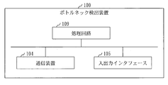
- the bottleneck detection device 100 includes a processing circuit 109.
- the processing circuit 109 is hardware that implements all or a part of the information extracting unit 111, the processing period determining unit 112, the used device determining unit 113, the used time calculating unit 114, the bottleneck detecting unit 115, and the sorting unit 116.
- the processing circuit 109 may be dedicated hardware or the processor 101 that executes a program stored in the memory 102.
- the processing circuit 109 is dedicated hardware, the processing circuit 109 is, for example, a single circuit, a composite circuit, a programmed processor, a parallel programmed processor, an ASIC, an FPGA, or a combination thereof.
- ASIC is an abbreviation for Application Specific Integrated Circuit
- FPGA is an abbreviation for Field Programmable Gate Array.
- the bottleneck detection device 100 may include a plurality of processing circuits replacing the processing circuit 109. The plurality of processing circuits share the role of the processing circuit 109.
- processing circuit 109 some functions may be realized by dedicated hardware, and the remaining functions may be realized by software or firmware.
- the processing circuit 109 can be realized by hardware, software, firmware, or a combination thereof.
- Embodiments are merely examples of preferred embodiments, and are not intended to limit the technical scope of the present invention. Embodiments may be implemented partially or in combination with other embodiments. The procedure described using the flowchart and the like may be appropriately changed.
- 100 bottleneck detection device 101 processor, 102 memory, 103 auxiliary storage device, 104 communication device, 105 input / output interface, 109 processing circuit, 111 information extraction unit, 112 processing period determination unit, 113 used device determination unit, 114 usage time Calculator, 115 ⁇ bottleneck detector, 116 # sorter, 120 # storage, 121 # production plan data, 122 # production procedure data, 123 # production equipment data, 124 # use period data, 125 # use time data, 126, 127 # bottleneck data.
Landscapes
- Engineering & Computer Science (AREA)
- General Engineering & Computer Science (AREA)
- Manufacturing & Machinery (AREA)
- Quality & Reliability (AREA)
- Physics & Mathematics (AREA)
- General Physics & Mathematics (AREA)
- Automation & Control Theory (AREA)
- Management, Administration, Business Operations System, And Electronic Commerce (AREA)
Abstract
Selon la présente invention, une unité de détermination de période de traitement (112) détermine, pour chaque paire type de machine et étape de production, une période de traitement pendant laquelle l'étape de production doit être effectuée, sur la base d'une date d'échéance de production pour le type de machine, du nombre d'articles à produire pour le type de machine, et d'un temps de traitement par nombre d'unité pour l'étape de production dans une procédure de production pour le type de machine. Une unité de détermination de dispositif à utiliser (113) détermine, pour chaque paire type de machine et étape de production, un dispositif de production qui doit être utilisé à l'étape de production en tant que dispositif à utiliser, sur la base de données de dispositif de production indiquant un ou plusieurs dispositifs de production pour l'étape de production. Une unité de calcul de temps d'utilisation (114) calcule, pour chaque dispositif de production, sur la base de la période de traitement pour chaque paire type de machine et étape de production ainsi que du dispositif à utiliser pour la paire type de machine et étape de production, un temps d'utilisation du dispositif de production dans une période cible. Une unité de détection de goulot d'étranglement (115) détecte un dispositif de production qui constitue un goulot d'étranglement dans la période cible sur la base des temps d'utilisation des dispositifs de production individuels dans la période cible.
Priority Applications (1)
| Application Number | Priority Date | Filing Date | Title |
|---|---|---|---|
| PCT/JP2018/025065 WO2020008501A1 (fr) | 2018-07-02 | 2018-07-02 | Dispositif de détection de goulot d'étranglement et procédé de détection de goulot d'étranglement |
Applications Claiming Priority (1)
| Application Number | Priority Date | Filing Date | Title |
|---|---|---|---|
| PCT/JP2018/025065 WO2020008501A1 (fr) | 2018-07-02 | 2018-07-02 | Dispositif de détection de goulot d'étranglement et procédé de détection de goulot d'étranglement |
Publications (1)
| Publication Number | Publication Date |
|---|---|
| WO2020008501A1 true WO2020008501A1 (fr) | 2020-01-09 |
Family
ID=69059503
Family Applications (1)
| Application Number | Title | Priority Date | Filing Date |
|---|---|---|---|
| PCT/JP2018/025065 Ceased WO2020008501A1 (fr) | 2018-07-02 | 2018-07-02 | Dispositif de détection de goulot d'étranglement et procédé de détection de goulot d'étranglement |
Country Status (1)
| Country | Link |
|---|---|
| WO (1) | WO2020008501A1 (fr) |
Cited By (1)
| Publication number | Priority date | Publication date | Assignee | Title |
|---|---|---|---|---|
| CN116205023A (zh) * | 2022-07-12 | 2023-06-02 | 上海奔曜科技有限公司 | 机器人智能实验室的设计方法、装置、设备和存储介质 |
Citations (9)
| Publication number | Priority date | Publication date | Assignee | Title |
|---|---|---|---|---|
| JPH05101073A (ja) * | 1991-10-04 | 1993-04-23 | Toppan Printing Co Ltd | 生産計画立案装置 |
| JPH10289274A (ja) * | 1997-04-16 | 1998-10-27 | Yokogawa Electric Corp | スケジューリングシステム |
| JPH11333674A (ja) * | 1998-05-26 | 1999-12-07 | Matsushita Electric Works Ltd | 多段ジョブショップ型生産の生産計画立案方法 |
| JP2000084801A (ja) * | 1998-09-14 | 2000-03-28 | Mitsubishi Electric Corp | 循環型製造プロセス物流制御方法および装置 |
| JP2003141214A (ja) * | 2001-10-30 | 2003-05-16 | Mitsubishi Electric Corp | 生産計画作成システム、生産計画作成方法、および生産計画の作成をコンピュータに実行させるためのプログラム |
| JP2004145436A (ja) * | 2002-10-22 | 2004-05-20 | Matsushita Electric Ind Co Ltd | 生産計画作成方法及びその装置 |
| JP2006039852A (ja) * | 2004-07-26 | 2006-02-09 | Toshiba Corp | 装置優先順位調整システム、装置優先順位調整方法及びプログラム |
| JP2010165283A (ja) * | 2009-01-19 | 2010-07-29 | Kobe Steel Ltd | 設備負荷計画作成装置、該方法、該プログラムおよび記録媒体 |
| JP2015087803A (ja) * | 2013-10-28 | 2015-05-07 | 株式会社日立製作所 | 部品設備割付装置、部品設備割付方法、及びプログラム |
-
2018
- 2018-07-02 WO PCT/JP2018/025065 patent/WO2020008501A1/fr not_active Ceased
Patent Citations (9)
| Publication number | Priority date | Publication date | Assignee | Title |
|---|---|---|---|---|
| JPH05101073A (ja) * | 1991-10-04 | 1993-04-23 | Toppan Printing Co Ltd | 生産計画立案装置 |
| JPH10289274A (ja) * | 1997-04-16 | 1998-10-27 | Yokogawa Electric Corp | スケジューリングシステム |
| JPH11333674A (ja) * | 1998-05-26 | 1999-12-07 | Matsushita Electric Works Ltd | 多段ジョブショップ型生産の生産計画立案方法 |
| JP2000084801A (ja) * | 1998-09-14 | 2000-03-28 | Mitsubishi Electric Corp | 循環型製造プロセス物流制御方法および装置 |
| JP2003141214A (ja) * | 2001-10-30 | 2003-05-16 | Mitsubishi Electric Corp | 生産計画作成システム、生産計画作成方法、および生産計画の作成をコンピュータに実行させるためのプログラム |
| JP2004145436A (ja) * | 2002-10-22 | 2004-05-20 | Matsushita Electric Ind Co Ltd | 生産計画作成方法及びその装置 |
| JP2006039852A (ja) * | 2004-07-26 | 2006-02-09 | Toshiba Corp | 装置優先順位調整システム、装置優先順位調整方法及びプログラム |
| JP2010165283A (ja) * | 2009-01-19 | 2010-07-29 | Kobe Steel Ltd | 設備負荷計画作成装置、該方法、該プログラムおよび記録媒体 |
| JP2015087803A (ja) * | 2013-10-28 | 2015-05-07 | 株式会社日立製作所 | 部品設備割付装置、部品設備割付方法、及びプログラム |
Cited By (2)
| Publication number | Priority date | Publication date | Assignee | Title |
|---|---|---|---|---|
| CN116205023A (zh) * | 2022-07-12 | 2023-06-02 | 上海奔曜科技有限公司 | 机器人智能实验室的设计方法、装置、设备和存储介质 |
| CN116205023B (zh) * | 2022-07-12 | 2024-03-08 | 上海奔曜科技有限公司 | 机器人智能实验室的设计方法、装置、设备和存储介质 |
Similar Documents
| Publication | Publication Date | Title |
|---|---|---|
| US10877962B2 (en) | Deferred update of database hashcode in blockchain | |
| CN113383364B (zh) | 验证人节点选择方法、电子设备、系统及介质 | |
| US10212844B2 (en) | System and method for improving fan life in an information handling system | |
| CN107133856B (zh) | 风险订单的控制方法和装置 | |
| CN115033453B (zh) | 异常检测方法、装置、设备、存储介质及程序 | |
| JP2019057276A5 (fr) | ||
| CN110427259A (zh) | 一种任务处理方法及装置 | |
| WO2024183510A1 (fr) | Procédé et appareil de sélection de scénario de test, dispositif, et support de stockage | |
| US11042457B2 (en) | Application updates | |
| CN108228442A (zh) | 一种异常节点的检测方法及装置 | |
| CN111091287A (zh) | 风险对象识别方法、装置以及计算机设备 | |
| WO2020008501A1 (fr) | Dispositif de détection de goulot d'étranglement et procédé de détection de goulot d'étranglement | |
| CN104636279A (zh) | 地址分配识别方法和地址分配识别电路 | |
| CN108932241B (zh) | 日志数据统计方法、装置及节点 | |
| CN105824934A (zh) | 查找分布式etl中慢节点的方法和装置 | |
| CN110083775B (zh) | 一种推荐资源的配置方法及配置装置 | |
| CN108595685B (zh) | 一种数据处理方法及装置 | |
| CN107656927B (zh) | 一种特征选择方法及设备 | |
| CN114048231A (zh) | 数据处理方法、装置及计算机程序产品 | |
| CN107516114B (zh) | 一种时间序列处理方法及装置 | |
| WO2018207322A1 (fr) | Dispositif et programme de collecte de données | |
| CN118335267A (zh) | 一种基于化学表面处理的橡胶塑形强度优化方法及装置 | |
| CN109690584A (zh) | 信息处理装置、信息处理方法及信息处理程序 | |
| JP6571027B2 (ja) | データ格納装置及びデータ格納プログラム | |
| US8271981B2 (en) | Detecting an extraordinary behavior |
Legal Events
| Date | Code | Title | Description |
|---|---|---|---|
| 121 | Ep: the epo has been informed by wipo that ep was designated in this application |
Ref document number: 18925483 Country of ref document: EP Kind code of ref document: A1 |
|
| NENP | Non-entry into the national phase |
Ref country code: DE |
|
| 122 | Ep: pct application non-entry in european phase |
Ref document number: 18925483 Country of ref document: EP Kind code of ref document: A1 |
|
| NENP | Non-entry into the national phase |
Ref country code: JP |