WO2020008521A1 - Moteur à induction linéaire et ascenseur - Google Patents
Moteur à induction linéaire et ascenseur Download PDFInfo
- Publication number
- WO2020008521A1 WO2020008521A1 PCT/JP2018/025190 JP2018025190W WO2020008521A1 WO 2020008521 A1 WO2020008521 A1 WO 2020008521A1 JP 2018025190 W JP2018025190 W JP 2018025190W WO 2020008521 A1 WO2020008521 A1 WO 2020008521A1
- Authority
- WO
- WIPO (PCT)
- Prior art keywords
- induction motor
- linear induction
- magnetic
- slot
- gap
- Prior art date
- Legal status (The legal status is an assumption and is not a legal conclusion. Google has not performed a legal analysis and makes no representation as to the accuracy of the status listed.)
- Ceased
Links
Images


Classifications
-
- B—PERFORMING OPERATIONS; TRANSPORTING
- B66—HOISTING; LIFTING; HAULING
- B66B—ELEVATORS; ESCALATORS OR MOVING WALKWAYS
- B66B11/00—Main component parts of lifts in, or associated with, buildings or other structures
- B66B11/04—Driving gear ; Details thereof, e.g. seals
-
- B—PERFORMING OPERATIONS; TRANSPORTING
- B66—HOISTING; LIFTING; HAULING
- B66B—ELEVATORS; ESCALATORS OR MOVING WALKWAYS
- B66B9/00—Kinds or types of lifts in, or associated with, buildings or other structures
- B66B9/02—Kinds or types of lifts in, or associated with, buildings or other structures actuated mechanically otherwise than by rope or cable
-
- H—ELECTRICITY
- H02—GENERATION; CONVERSION OR DISTRIBUTION OF ELECTRIC POWER
- H02K—DYNAMO-ELECTRIC MACHINES
- H02K41/00—Propulsion systems in which a rigid body is moved along a path due to dynamo-electric interaction between the body and a magnetic field travelling along the path
- H02K41/02—Linear motors; Sectional motors
- H02K41/025—Asynchronous motors
Definitions
- the present invention relates to a linear induction motor and an elevator using the same.
- the linear induction motor since the linear induction motor is installed in a narrow space along the rope, the linear induction motor needs to be reduced in size, such as narrowing.
- the efficiency is reduced. Therefore, if an attempt is made to suppress a decrease in efficiency by reducing the gap length, a loss increases due to a harmonic of a secondary current generated by slot ripple of the magnetic flux, thereby limiting the improvement in efficiency.
- the present invention provides a linear induction motor capable of improving efficiency while reducing the size, and an elevator using the same.
- a linear induction motor includes a pair of primary cores, and a belt-shaped secondary conductor that passes through a gap between the pair of primary cores.
- the primary core includes a plurality of teeth portions and a plurality of slots adjacent to the plurality of teeth portions and provided with windings, and the openings of the slots are covered with a magnetic material.
- an elevator according to the present invention is one in which a car is driven up and down by a linear induction motor, and the linear induction motor is the linear induction motor according to the present invention, , Are suspended in the hoistway by the secondary conductor.
- the efficiency of a linear induction motor and an elevator using the same is improved.
- FIG. 4 shows a flow of a main magnetic flux in the linear induction motor of FIG. 3.
- FIG. 4 is a partial sectional view of the linear induction motor of FIG. 3.
- 3 shows a magnetic flux path in a double-sided linear induction motor (non-magnetic wedge 51).
- 3 shows a magnetic flux path in a double-sided linear induction motor (magnetic wedge 31). The path of the magnetic flux when (pole pitch / gap length) is reduced is shown (non-magnetic wedge 51).
- FIG. 9 shows a magnetic flux path when (pole pitch / gap length) is reduced (magnetic wedge 51).
- 4 shows a magnetic flux path in a single-sided linear induction motor.
- 7 shows a magnetic flux distribution in an example in which the magnetic wedge according to the embodiment is applied.
- 4 shows a distribution of an induced current flowing through a secondary conductor belt in one example in which the magnetic wedge is applied in the present embodiment.
- the relationship between the ratio of the thrust when the magnetic wedge is applied to the thrust when the magnetic wedge is not applied and (pole pitch / gap length) is shown.
- the relationship between the ratio between the thrust when the magnetic wedge is applied and the thrust when the magnetic wedge is not applied and (slot width / slot pitch) is shown.
- the modification of a magnetic wedge is shown.
- the modification of a magnetic wedge is shown.
- the modification of a magnetic wedge is shown.
- the modification of a magnetic wedge is shown.
- the modification of a magnetic wedge is shown.
- the modification of a magnetic wedge is shown
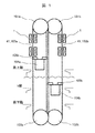
- FIG. 1 is a schematic configuration diagram of an elevator according to one embodiment of the present invention.
- two cars in one hoistway, two cars (104a, 104b) move in the directions opposite to each other between the top floor and the bottom floor.
- an endless wire rope 103a and a belt-like secondary conductor belt (hereinafter, referred to as “secondary conductor belt 41”) are wound around the upper pulley 101a and the lower pulley 102a.
- the wire rope 103a and the secondary conductor belt 41 are illustrated in an overlapping manner (the same applies to the wire rope 103b and the secondary conductor belt 41).
- the endless wire rope 103b and the secondary conductor belt 41 are wound around the upper pulley 101b and the lower pulley 102b.
- the wire ropes 103a and 103b and the secondary conductor belt 41 may be covered with a resin.
- the wire rope 103b to be hung and the other part of the secondary conductor belt 41 are respectively attached to one and the other of a pair of connecting portions 105b provided in the car 104b.
- the cars 104a and 104b are suspended by the secondary conductor belt 41 and the wire ropes 103a and 103b in the hoistway (not shown).
- the cars (104a and 104b) move in directions opposite to each other in one hoistway.
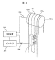
- FIG. 2 shows the configuration near the upper pulley in the elevator of FIG. Note that only the upper pulley 101a of the upper pulleys 101a and 101b in FIG. 1 is shown.
- the configuration near the upper pulley 101b is the same as the configuration near the upper pulley 101a shown in FIG.
- a plurality of (two in FIG. 2) wire ropes 103a are wound around the upper pulley 101a, and the secondary conductor belt 41 is wound between the two wire ropes 103a.
- the wire rope 103a is a known elevator rope made of a steel wire.
- the secondary conductor belt 41 is made of a flat and belt-shaped non-magnetic conductor.
- the linear induction motor 1 in the present embodiment is of a double-sided type, and includes a pair of primary cores on which a three-phase winding is applied.
- the pair of primary cores are opposed to each other with a predetermined gap therebetween, and are fixedly mounted in the hoistway so that the longitudinal direction of the primary cores extends along the direction in which the secondary conductor belt 41 extends vertically.
- the secondary conductor belt 41 passes through a gap between the upper and lower ends of the pair of primary cores in the longitudinal direction, between the primary cores.
- the primary core of the linear induction motor 1 is mounted above the uppermost floor (FIG. 1) in a space where the car does not reach.
- the inverter 201 supplies three-phase AC power of variable frequency and variable voltage to the three-phase winding of the linear induction motor 1. Thereby, the secondary conductor belt 41 is driven, and the car is driven. Further, the control device 202 converts a signal of a rotary encoder rotatably connected to the upper pulley 101a to detect rotation of the upper pulley 101a and a signal of a current sensor that detects output current from the inverter 201 to the three-phase winding. Based on this, the inverter 201 is controlled. This controls the speed of the car.
- the width dimension of the primary core perpendicular to the longitudinal direction can be reduced. For this reason, as shown in FIG. 2, the linear induction motor 1 can be installed in a narrow space in the hoistway and between the two wire ropes 103a.
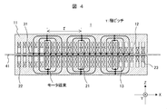
- FIG. 3 is a cross-sectional view showing a configuration of a linear induction motor according to one embodiment of the present invention. This figure shows a cross section of the linear induction motor 1 provided in the elevator shown in FIGS. 1 and 2 along the longitudinal direction (x direction in FIG. 3).
- the linear induction motor 1 includes a pair of primary cores 11 facing each other with a predetermined gap therebetween, and a secondary conductor belt 41 located in the gap between these primary cores. That is, the present embodiment is a so-called double-sided linear induction motor.
- the double-sided linear induction motor can reduce the vertical force acting on the secondary conductor but not contributing to the thrust, and is therefore suitable for driving a linearly extending secondary conductor like the elevator of FIG. .
- the primary side core 11 includes a plurality of teeth 12 and has a comb-shaped longitudinal cross section as shown in FIG.
- the pair of primary cores 11 are arranged symmetrically on both sides of the secondary conductor belt 41 with the linear portion of the secondary conductor belt 41 as the axis of symmetry. Therefore, the exposed end face of the tip of each tooth 12 in one primary core 11 and the exposed end face of the tip of each tooth 12 in the other primary core 11 face each other so as to overlap each other.
- a three-phase winding is applied to the primary core 11.
- the three-phase winding includes coils 22 and 23 wound around both ends of the primary core 11, and a coil 21 wound around a main portion including a central portion of the primary core 11 (a portion that applies thrust to the secondary conductor belt 41). Consists of The conductors forming the coils 21, 22, and 23 pass through the space between two adjacent teeth 12, that is, inside the slot 13, and pass outside the width direction (the y direction in the drawing) of the primary core 11.
- the coils 21, 22, and 23, that is, the portions of the three-phase windings located outside the primary core 11 in the width direction constitute coil ends (not shown).
- the opening of the slot 13 is closed by the magnetic wedge 31 and is in a fully closed state.
- the primary side core 11 is made of a magnetic material.
- primary core 11 is formed of a laminated body of electromagnetic steel sheets having a comb shape as shown in FIG. Thereby, iron loss (eddy current loss) can be reduced.
- the number of turns of the coils 22 and 23 is smaller than the number of turns of the coil 21 in one slot (in FIG. 3, the number of turns of the coil 21 is 1/2). This suppresses a so-called end effect, that is, a decrease in thrust caused by a sudden change in magnetic flux distribution at both ends of the primary core 11.
- FIG. 4 shows a flow of a main magnetic flux in the linear induction motor of FIG.
- FIG. 4 shows the flow of magnetic flux at a certain point when three-phase alternating current flows through the three-phase winding.
- a magnetic field having a pole pitch of ⁇ with three magnetic poles is generated.
- the motor magnetic flux flows through the gap between the teeth 12 of each primary core 11 and the primary core 11 and the secondary conductor belt 41 so as to circulate around each magnetic pole.
- These magnetic poles move along the longitudinal direction (x direction in FIG. 4) of the primary core 11 at a speed corresponding to the frequency of the three-phase alternating current and the number of magnetic poles.
- an induced current flows through the secondary conductor belt 41, and a thrust is generated on the secondary conductor belt 41 by the induced current and the magnetic flux passing through the secondary conductor belt 41.
- the number of magnetic poles and the pole pitch can be appropriately set by the configuration of the three-phase winding according to the configuration of the linear induction motor and desired characteristics.
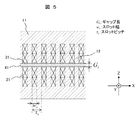
- FIG. 5 is a partial sectional view of the linear induction motor of FIG.
- the primary side core 11, the primary side core 11 in the longitudinal direction along the predetermined slot width w s of the slot (the space in which the coil 21 is stored) is at a predetermined slot pitch tau s A plurality is arranged.
- the slot pitch ⁇ s is the interval between two adjacent slots, and in the present embodiment, the width of the primary core 11 of the teeth 12 along the longitudinal direction is fixed, so that the slot width w s And the width of the teeth.
- the secondary conductor belt 41 passes through a gap of a predetermined gap length G t between the pair of primary-side core 11.
- the gap length Gt is the distance between the opposed teeth 12, that is, the distance between the end faces of the teeth 12 exposed in the gap.
- the magnetic wedge 31 is a wedge-shaped magnetic material, is fitted into the opening of the slot, and closes the opening of the slot.
- the end face of the magnetic wedge 31 exposed in the gap between the pair of primary cores 11 is located in substantially the same plane as the end face of the tooth 12 exposed in the gap. That is, the opposing surfaces of the pair of primary-side cores 11 have substantially no irregularities and are substantially flat surfaces.
- between the magnetic wedge 31 facing that is, the distance between the end faces of the magnetic wedge 31 exposed in the gap is substantially equal to the gap length G t.
- the distance between the end faces of the magnetic wedge 31, is equal to the gap length G t in substantially the entire region of the magnetic wedge 31 in the direction of the slot width, the configuration of the magnetic wedge 31, the gap length G t Has little effect on settings.
- the relative magnetic permeability of the magnetic material forming the magnetic wedge 31 is preferably smaller than the relative magnetic permeability of the magnetic material forming the primary core 11 (for example, an electromagnetic steel plate such as a silicon steel plate). of value ( ⁇ s (relative permeability): 1 ⁇ s ⁇ 100 ) and. Thereby, the slot ripple of the magnetic flux can be surely suppressed.
- the magnetic material constituting the magnetic wedge 31 for example, a mixture of a ferromagnetic powder such as an iron powder and a resin such as a glass resin, or a mixture of a ferromagnetic material and a non-magnetic material can be applied. . Thereby, the relative magnetic permeability of the magnetic wedge can be appropriately adjusted.
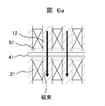
- FIGS. 6a and 6b show magnetic flux paths in a double-sided linear induction motor.
- the wedge-shaped member closing the slot opening is a non-magnetic wedge 51 made of a non-magnetic material.
- the wedge-shaped member is the magnetic wedge 31 in the present embodiment.
- the magnetic flux is applied to one of the two teeth 12 facing each other across the gap, the secondary conductor belt 41 in the gap, and the two opposite faces 12 across the gap. It flows along a path passing through the other of the two teeth 12. Since there is no magnetic flux path through the non-magnetic wedge 51, the magnetic flux concentrates on the aforementioned path. For this reason, slot ripple of magnetic flux occurs, and the efficiency of the linear induction motor decreases.
- the wedge-shaped member is the magnetic wedge 31
- a part of the magnetic flux is added to one of the two teeth 12 opposed to each other with a gap in addition to the same path as in FIG.
- the gap length can be reduced to compensate for a decrease in efficiency due to the reduction in width without increasing loss.
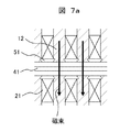
- FIGS. 7a and 7b show the paths of magnetic flux when (pole pitch / gap length) is reduced.
- the wedge-shaped member closing the slot opening is a non-magnetic wedge 51 made of a non-magnetic material.
- the wedge-shaped member is the magnetic wedge 31 in the present embodiment.
- the pole pitch (“ ⁇ ” in FIG. 4) relates to the number of magnetic poles, and thus to the speed of the moving magnetic field. That is, the pole pitch is a parameter related to the speed performance of the linear induction motor. Since the pole pitch relates to the configuration of the three-phase winding applied to the primary core, it also affects the slot width and the width of the teeth of the primary core. For example, in one configuration of the three-phase winding in the primary core having a predetermined length, the interval between two adjacent teeth 12 becomes narrow. The magnetic resistance between the teeth 12 sandwiching the wedge-shaped member is reduced.
- the gap length (“G t ” in FIG. 5) is related to the magnetic resistance between the two teeth 12 facing each other with the gap therebetween. Therefore, (pole pitch / gap length) corresponds to the ratio of the magnetoresistance between adjacent teeth and the magnetoresistance between opposing teeth.
- the wedge-shaped member is the magnetic wedge 31
- the degree of reduction in the magnetic resistance between adjacent teeth is smaller than the degree of reduction in the magnetic resistance between opposing teeth.
- FIG. 7B a path of the magnetic flux via the magnetic wedge 31 is generated between adjacent teeth. Since the magnetic flux flowing through this path does not pass through the secondary conductor belt 41, it does not contribute to the thrust of the linear induction motor. Therefore, when such an amount of magnetic flux increases, the improvement of the efficiency of the linear induction motor is limited even if the magnetic wedge is provided.
- the magnetic wedge is provided on the primary core of the two-sided linear induction motor
- FIG. 8 shows a magnetic flux path in a single-sided linear induction motor.
- the wedge-shaped member is a non-magnetic wedge 51.
- the magnetic wedge is effective in the double-sided linear induction motor as in the present embodiment.
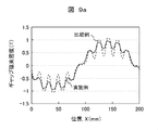
- FIG. 9A shows a magnetic flux distribution (solid line in the figure) in an example to which the magnetic wedge according to the present embodiment is applied.
- the vertical axis represents the gap magnetic flux density in the gap between the pair of primary cores, and the horizontal axis represents the position along the longitudinal direction of the linear induction motor.
- a broken line shows a magnetic flux distribution when the magnetic wedge in the example is replaced with a non-magnetic wedge.
- the use of a magnetic wedge reduces the spatial variation of the magnetic flux density, that is, the slot ripple of the magnetic flux.
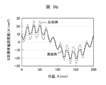
- FIG. 9B shows the distribution of the induced current flowing through the secondary conductor belt (solid line in the figure) in one example to which the magnetic wedge is applied in the present embodiment.
- the vertical axis represents the secondary conductor current density
- the horizontal axis represents the position along the longitudinal direction of the linear induction motor.
- a broken line shows a current distribution when the magnetic wedge in the example is replaced with a non-magnetic wedge.
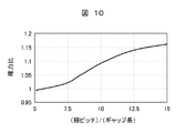
- FIG. 10 shows the relationship between the ratio between the thrust when the magnetic wedge is applied and the thrust when the magnetic wedge is not applied and (pole pitch / gap length).
- the vertical axis represents the thrust ratio
- the horizontal axis represents (pole pitch / gap length).
- the thrust ratio is (thrust when the magnetic wedge is applied / thrust when the magnetic wedge is not applied).
- the case where the magnetic wedge is not applied may be the case where the non-magnetic wedge is used or the case where the wedge-shaped member is not used, that is, the case where the slot opening is opened without being closed.
- FIG. 11 shows the relationship between the ratio of the thrust when the magnetic wedge is applied and the thrust when the magnetic wedge is not applied, and (slot width / slot pitch).
- the slot width and slot pitch are respectively w s and ⁇ s shown in FIG. 11, the vertical axis represents the thrust ratio as in FIG. 10, and the horizontal axis represents (slot width / slot pitch).
- slot width / slot pitch can be one index indicating the design balance between the size of the primary core (the length dimension in the present embodiment) and the thrust.
- (slot width / slot pitch) is preferably 0.5, but can be appropriately set in the range shown in the figure according to the desired size and thrust of the primary core.
- the thrust ratio changes depending on (slot width / slot pitch). In the range (slot width / slot pitch) shown in the figure, the thrust ratio is larger than 1, and the efficiency can be surely improved.
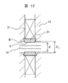
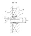
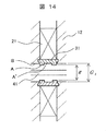
- FIGS. 12 to 17 show modified examples of the magnetic wedge.
- Each drawing is a partial sectional view of the linear induction motor.
- the configuration of the linear induction motor other than the magnetic wedge is the same as in the above-described embodiment (FIG. 3).
- the magnetic wedge 31 has a portion projecting from the primary core into the gap between the pair of primary cores. That is, as shown in FIGS. 12 to 14, the distance g between the distal end faces A of the magnetic wedges 31 exposed in the gap is the distance between the opposed teeth 12, that is, the distance between the end faces B of the teeth 12 exposed in the gap, that is, the gap. less than the length G t (g ⁇ G t) .
- the exposed surface of the magnetic wedge 31 shown in FIG. 12 facing the gap is in the width direction of the slot, that is, in the entire width direction of the magnetic wedge 31 in the longitudinal direction of the primary core (hereinafter, simply referred to as “width direction”).
- the teeth 12 protrude into the gap from a plane including the exposed surface. That is, since the entire exposed surface of the magnetic wedge 31 is the distal end surface, the entire exposed surface of the magnetic wedge 31, a relationship of the aforementioned g ⁇ G t.
- the exposed surface of the magnetic wedge 31 shown in FIG. 13 toward the gap only the exposed surface A at the center of the center in the width direction of the magnetic wedge 31 and the left and right sides of the center protrudes into the gap. . That is, since the exposed surface of the central portion is the distal end surface A, the exposed surface of the center in the width direction of the magnetic wedge 31, a relationship of the aforementioned g ⁇ G t. Incidentally, the exposed surface A 'the distance between the right and left side portions in the width direction of the magnetic wedge 31 is equal to the gap length G t.
- g ⁇ g ' ⁇ so that the G t, g' may be set.
- the exposed surface of the magnetic wedge 31 shown in FIG. 14 facing the gap is such that only the exposed surfaces A on the left and right sides of the central portion in the width direction of the magnetic wedge 31 and the left and right sides of the central portion project into the gap. I do. That is, since the exposed surface of the left and right sides is the distal end surface A, the exposed surface of the right and left side portions in the width direction of the magnetic wedge 31, a relationship of the aforementioned g ⁇ G t. Incidentally, the exposed surface A 'the distance between the center in the width direction of the magnetic wedge 31 is equal to the gap length G t.
- g ⁇ g ' ⁇ so that the G t, g' may be set.
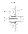
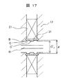
- FIGS. 15 to 17 at least a part of the surface of the magnetic wedge 31 exposed toward the gap is located in the slot. That is, as shown in FIGS. 15-17, the distance g between the surface C located in the slot, the distance between the end surfaces B of the teeth 12 exposed in the gap, i.e. greater than the gap length G t (g> G t ).
- the exposed surface facing the gap of the magnetic wedge 31 shown in FIG. 15 is located in the slot over the entire width of the magnetic wedge 31. That is, the above-described relationship of g> Gt holds for the entire exposed surface of the magnetic wedge 31.
- the exposed surface facing the gap of the magnetic wedge 31 shown in FIG. 16 has only the central exposed surface C of the central portion in the width direction of the magnetic wedge 31 and the right and left sides of the central portion located in the slot. . That is, for the exposed surface of the center in the width direction of the magnetic wedge 31, a relationship of the aforementioned g> G t. Incidentally, the exposed surface C 'the distance between the right and left side portions in the width direction of the magnetic wedge 31 is equal to the gap length G t.
- a g ' G t.
- the present invention is not limited to this, 'so that the> G t, g'g> g may be set.
- the exposed surface facing the gap of the magnetic wedge 31 shown in FIG. 17 is such that only the exposed surfaces A on the left and right sides of the central portion in the width direction of the magnetic wedge 31 and the left and right sides of the central portion are located in the slot. I do. That is, for the exposed surface of the right and left side portions in the width direction of the magnetic wedge 31, a relationship of the aforementioned g> G t. Incidentally, the exposed surface C 'the distance between the center in the width direction of the magnetic wedge 31 is equal to the gap length G t.
- a g ' G t.
- the present invention is not limited to this, 'so that the> G t, g'g> g may be set.
- the magnetic wedges of the modified examples of FIGS. 12 to 17 can also spread the magnetic flux from the teeth 12 to the adjacent slots in the lateral direction, similarly to the above-described embodiment. Therefore, the slot ripple of the magnetic flux is reduced, and the efficiency of the linear induction motor is improved.
- the magnetic flux can be surely spread laterally from the teeth 12 to the adjacent slots. Further, according to the magnetic wedges of the modified examples shown in FIGS. 15 to 17, the gap length Gt can be easily set without considering the structure of the magnetic wedges.
- the magnetic wedges of the present embodiment and FIGS. 12 to 17 can be appropriately selected and used.
- the present invention is not limited to the modified examples of FIGS. 12 to 17, but may be modified such that a part of the surface of the magnetic wedge 31 exposed toward the gap projects into the gap and another part is located in the slot. It is possible.
- the slot ripple of the magnetic flux in the gap between the pair of primary cores of the two-sided linear induction motor is reduced, and the harmonic current generated in the secondary conductor belt is reduced. Can be reduced.
- the efficiency of the double-sided linear induction motor can be improved.
- the width of the double-sided linear induction motor can be reduced without lowering the efficiency.
- an elevator driven by a double-sided linear induction motor can be space-saving and highly efficient.
- the present invention is not limited to the embodiments described above, but includes various modifications.
- the above-described embodiments have been described in detail for easy understanding of the present invention, and are not necessarily limited to those having all of the described configurations. Further, for a part of the configuration of each embodiment, it is possible to add, delete, or replace another configuration.
- the configuration of the elevator is not limited to the configuration of FIG. 1, and a configuration in which the car and the counterweight are suspended in a sling manner by the rope and the secondary conductor belt may be used.
- a simple guide means may be provided outside the pair of primary cores, adjacent to the longitudinal ends of the primary core.
- a part of the tooth may be extended in the slot width direction to cover the opening of the slot.
- the slot it is preferable that the slot be a so-called semi-closed type.
- the protrusion of the magnetic wedge 31 shown in FIGS. 12 to 14 into the gap may be replaced with a non-magnetic material to serve as a guide means for stabilizing the position of the secondary conductor belt in the gap.
- SYMBOLS 1 Linear induction motor, 11 ... Primary side core, 12 ... Teeth, 13 ... Slot, 21, 22, 23 ... Coil, 31 ... Magnetic wedge, 41 ... Secondary conductor belt, 51 ... Non-magnetic wedge, 52 ... Magnetic body Plate, 101a, 101b: Upper pulley, 102a, 102b: Lower pulley, 103a, 103b: Wire rope, 104a, 104b: Car, 105a, 105b: Connection, 201: Inverter, 202: Control device, 203: Rotary encoder , 204 ... current sensor
Landscapes
- Engineering & Computer Science (AREA)
- Mechanical Engineering (AREA)
- Structural Engineering (AREA)
- Civil Engineering (AREA)
- Physics & Mathematics (AREA)
- Chemical & Material Sciences (AREA)
- Combustion & Propulsion (AREA)
- Electromagnetism (AREA)
- Power Engineering (AREA)
- Automation & Control Theory (AREA)
- Linear Motors (AREA)
Abstract
L'invention concerne un moteur à induction linéaire de petite taille mais permettant d'obtenir un rendement amélioré, et un ascenseur faisant appel au moteur à induction linéaire. Le moteur à induction linéaire comprend deux noyaux primaires (11) et un conducteur secondaire en forme de courroie (41) passant à travers un espace séparant les deux noyaux primaires (11), les noyaux primaires (11) comprenant chacun une pluralité de parties dents (12) et une pluralité de fentes (13) adjacentes à la pluralité de parties dents (12) et dotées d'enroulements (21), et une ouverture entre les fentes (13) étant recouverte d'un corps magnétique (31).
Priority Applications (1)
| Application Number | Priority Date | Filing Date | Title |
|---|---|---|---|
| PCT/JP2018/025190 WO2020008521A1 (fr) | 2018-07-03 | 2018-07-03 | Moteur à induction linéaire et ascenseur |
Applications Claiming Priority (1)
| Application Number | Priority Date | Filing Date | Title |
|---|---|---|---|
| PCT/JP2018/025190 WO2020008521A1 (fr) | 2018-07-03 | 2018-07-03 | Moteur à induction linéaire et ascenseur |
Publications (1)
| Publication Number | Publication Date |
|---|---|
| WO2020008521A1 true WO2020008521A1 (fr) | 2020-01-09 |
Family
ID=69060464
Family Applications (1)
| Application Number | Title | Priority Date | Filing Date |
|---|---|---|---|
| PCT/JP2018/025190 Ceased WO2020008521A1 (fr) | 2018-07-03 | 2018-07-03 | Moteur à induction linéaire et ascenseur |
Country Status (1)
| Country | Link |
|---|---|
| WO (1) | WO2020008521A1 (fr) |
Cited By (1)
| Publication number | Priority date | Publication date | Assignee | Title |
|---|---|---|---|---|
| WO2023209727A1 (fr) * | 2022-04-27 | 2023-11-02 | INDIAN INSTITUTE OF TECHNOLOGY MADRAS (IIT Madras) | Moteur à induction linéaire à effets d'extrémité réduits |
Citations (5)
| Publication number | Priority date | Publication date | Assignee | Title |
|---|---|---|---|---|
| JPS58105755U (ja) * | 1982-01-13 | 1983-07-19 | 三菱電機株式会社 | 磁性楔 |
| JPS6277030A (ja) * | 1985-09-27 | 1987-04-09 | Hitachi Ltd | 回転電機の磁性楔 |
| JP2001095225A (ja) * | 1999-09-20 | 2001-04-06 | Yaskawa Electric Corp | リニアモータ |
| JP2005503095A (ja) * | 2001-04-09 | 2005-01-27 | ビーイーアイ・テクノロジーズ・インク | 鉄心複合アーマチャ組立を有するリニア・ブラシレス・dcモータ |
| JP2005239418A (ja) * | 2004-03-01 | 2005-09-08 | Hitachi Ltd | エレベーター装置 |
-
2018
- 2018-07-03 WO PCT/JP2018/025190 patent/WO2020008521A1/fr not_active Ceased
Patent Citations (5)
| Publication number | Priority date | Publication date | Assignee | Title |
|---|---|---|---|---|
| JPS58105755U (ja) * | 1982-01-13 | 1983-07-19 | 三菱電機株式会社 | 磁性楔 |
| JPS6277030A (ja) * | 1985-09-27 | 1987-04-09 | Hitachi Ltd | 回転電機の磁性楔 |
| JP2001095225A (ja) * | 1999-09-20 | 2001-04-06 | Yaskawa Electric Corp | リニアモータ |
| JP2005503095A (ja) * | 2001-04-09 | 2005-01-27 | ビーイーアイ・テクノロジーズ・インク | 鉄心複合アーマチャ組立を有するリニア・ブラシレス・dcモータ |
| JP2005239418A (ja) * | 2004-03-01 | 2005-09-08 | Hitachi Ltd | エレベーター装置 |
Cited By (1)
| Publication number | Priority date | Publication date | Assignee | Title |
|---|---|---|---|---|
| WO2023209727A1 (fr) * | 2022-04-27 | 2023-11-02 | INDIAN INSTITUTE OF TECHNOLOGY MADRAS (IIT Madras) | Moteur à induction linéaire à effets d'extrémité réduits |
Similar Documents
| Publication | Publication Date | Title |
|---|---|---|
| KR950001902B1 (ko) | 리니어모터(linear motor) 엘리베이터 | |
| JPH0439285A (ja) | リニアモータエレベーター | |
| JPH05186165A (ja) | リニアモータ駆動方式エレベータ装置 | |
| JPH05252724A (ja) | エレベータ用リニアモータ | |
| JP4993713B2 (ja) | エレベータの乗籠への給電装置 | |
| WO2020008521A1 (fr) | Moteur à induction linéaire et ascenseur | |
| US5174416A (en) | Linear induction motor for elevator | |
| JP5089113B2 (ja) | エレベータのかごへの非接触給電装置 | |
| EP0599331A1 (fr) | Ascenceur propulsé par un moteur linéaire | |
| JP2583697B2 (ja) | リニアモータエレベーター | |
| CN204498022U (zh) | 一种混合励磁非接触悬浮导向系统 | |
| JP2019187164A (ja) | 回転電機、および、エレベーター巻上げシステム | |
| JP4176289B2 (ja) | エレベータ装置 | |
| JPH1198725A (ja) | モータおよびエレベータ | |
| JP5932486B2 (ja) | エレベーター装置 | |
| CN104682772A (zh) | 一种混合励磁非接触悬浮导向系统 | |
| JP7824437B2 (ja) | エレベータモータ | |
| US789765A (en) | Rope-drive for elevators. | |
| KR940011705B1 (ko) | 엘리베이터용 리니어유도전동기 | |
| CN100393601C (zh) | 电梯装置 | |
| KR0137949Y1 (ko) | 선형 구동 방식 엘리베이터장치 | |
| JPH0439286A (ja) | リニアモータエレベータ | |
| KR100231819B1 (ko) | 리니어모터 | |
| JPH09331667A (ja) | リニア誘導モータ | |
| JPH11220847A (ja) | 永久磁石モータおよびそれを用いたエレベータ装置 |
Legal Events
| Date | Code | Title | Description |
|---|---|---|---|
| 121 | Ep: the epo has been informed by wipo that ep was designated in this application |
Ref document number: 18925167 Country of ref document: EP Kind code of ref document: A1 |
|
| NENP | Non-entry into the national phase |
Ref country code: DE |
|
| 122 | Ep: pct application non-entry in european phase |
Ref document number: 18925167 Country of ref document: EP Kind code of ref document: A1 |
|
| NENP | Non-entry into the national phase |
Ref country code: JP |