WO2020008547A1 - 疲労抑制方法及び乗員支援装置 - Google Patents
疲労抑制方法及び乗員支援装置 Download PDFInfo
- Publication number
- WO2020008547A1 WO2020008547A1 PCT/JP2018/025313 JP2018025313W WO2020008547A1 WO 2020008547 A1 WO2020008547 A1 WO 2020008547A1 JP 2018025313 W JP2018025313 W JP 2018025313W WO 2020008547 A1 WO2020008547 A1 WO 2020008547A1
- Authority
- WO
- WIPO (PCT)
- Prior art keywords
- vehicle
- occupant
- fatigue
- unit
- suppressing
- Prior art date
- Legal status (The legal status is an assumption and is not a legal conclusion. Google has not performed a legal analysis and makes no representation as to the accuracy of the status listed.)
- Ceased
Links
Images


Classifications
-
- G—PHYSICS
- G08—SIGNALLING
- G08G—TRAFFIC CONTROL SYSTEMS
- G08G1/00—Traffic control systems for road vehicles
- G08G1/16—Anti-collision systems
Definitions
- the present invention relates to a fatigue suppression method and an occupant support device.
- Patent Document 1 discloses a brain activating effect in which a hypersonic sound that combines audible sound and ultrahigh-frequency sound is applied to a human to activate a basic brain and a basic brain network system including the human brain stem, thalamus, and hypothalamus. A vibrating body has been proposed to guide the vibration.
- Patent Document 1 since the technology described in Patent Document 1 continuously applies hypersonic sound to humans, there is a possibility that a sufficient brain activation effect may not be obtained when used for occupants of a vehicle. There was a problem.
- the present invention has been made in view of the above-described problems, and has as its object to provide a fatigue suppression method and an occupant support method capable of sufficiently obtaining a brain activation effect in a situation where an occupant of a vehicle is easily fatigued. It is to provide a device.
- a fatigue suppression method and an occupant assistance device based on vehicle information on a vehicle and surrounding conditions of the vehicle, is the occupant of the vehicle in a state in which the occupant is easily fatigued? It is determined whether or not the occupant is easily fatigued, and if it is determined that the occupant is easily fatigued, the fatigue suppression unit is operated to suppress the occupant fatigue by activating the occupant's brain stem.
- a sufficient brain activation effect can be obtained even when the occupant is easily fatigued during driving of the vehicle.
- FIG. 1 is a block diagram showing a configuration of an occupant assistance device according to one embodiment of the present invention.
- FIG. 2 is a flowchart illustrating a procedure of fatigue suppression processing by the occupant assistance device according to one embodiment of the present invention.
- FIG. 3 is a graph showing the results of verification of fatigue suppression by the hypersonic sound method.
- FIG. 1 is a block diagram illustrating a configuration of the occupant assistance device according to the present embodiment.
- FIG. 2 is a flowchart illustrating a procedure of a fatigue suppression process performed by the occupant support device according to the present embodiment.
- the occupant assistance device 1 includes a processing unit 100 (controller) and a fatigue suppression unit 50.
- the occupant assistance device 1 is mounted on a vehicle (not shown), and the processing unit 100 is communicably connected to an on-vehicle sensor 90 and a fatigue suppression unit 50 mounted on the vehicle.
- the vehicle-mounted sensor 90 includes an object detection sensor mounted on the vehicle, such as a laser radar, a millimeter-wave radar, or a camera, for detecting an object existing around the vehicle.
- the in-vehicle sensor 90 may include a plurality of different types of object detection sensors.
- the on-vehicle sensor 90 detects the environment around the vehicle.
- the in-vehicle sensor 90 detects a moving object including another vehicle, a motorcycle, a bicycle, a pedestrian, and a stationary object including a stopped vehicle, and detects the position, posture, size, speed, and acceleration of the moving object and the stationary object with respect to the vehicle. , Deceleration, yaw rate, etc. may be detected.
- the on-vehicle sensor 90 may output, as a detection result, the behavior of a two-dimensional object in a zenith view (also referred to as a plan view) viewed from the air above the vehicle, for example.
- a zenith view also referred to as a plan view
- the in-vehicle sensor 90 may detect a sign (a road sign or a sign displayed on a road surface), a guide rail, or the like existing around the vehicle.
- the on-vehicle sensor 90 may detect the rotational speed or the rotational speed difference of the wheels provided in the vehicle, and detect the slipperiness of the road surface of the lane in which the vehicle is traveling.
- the vehicle-mounted sensor 90 detects the state of the vehicle in addition to the environment around the vehicle.
- the on-vehicle sensor 90 may detect the moving speed of the vehicle (moving speed in the front-rear direction, the left-right direction, the turning speed), the turning angle of the wheels included in the vehicle, and the changing speed of the turning angle. .
- Processing unit 100 controls fatigue suppression unit 50 based on the detection result by vehicle-mounted sensor 90.
- the processing unit 100 (an example of a control unit or a controller) is a general-purpose microcomputer including a CPU (central processing unit), a memory, and an input / output unit.
- a computer program occupant support program for functioning as a part of the occupant support device is installed.
- the processing unit 100 functions as a plurality of information processing circuits (10, 20, 30) included in the occupant assistance device.
- a plurality of information processing circuits (10, 20, 30) included in the driving support device are realized by software.
- the plurality of information processing circuits (10, 20, 30) may be configured by individual hardware.
- the information processing circuit (10, 20, 30) may also be used as an electronic control unit (ECU) used for other control related to the vehicle.
- ECU electronice control unit
- the processing unit 100 includes an acquisition unit 10, a load evaluation unit 20, and an environment determination unit 30 as a plurality of information processing circuits (10, 20, 30).
- the acquisition unit 10 extracts vehicle information necessary for evaluating the physical load of the occupant from the vehicle information (information about the environment around the vehicle and information about the state of the vehicle) detected by the on-vehicle sensor 90, or The vehicle information necessary for evaluating the physical load of the occupant is transmitted to the load evaluator 20.
- the moving speed of the vehicle forward / backward, left / right moving speed, turning speed
- the moving speed of an object in front of or on the side of the vehicle Lane width of the lane in which the vehicle is located, distance between objects on the side of the vehicle, lightness outside the vehicle, slipperiness of the road surface of the lane on which the vehicle is traveling, longitudinal acceleration of the vehicle, acceleration in the vertical direction, The acceleration in the left-right direction, the changing speed of the turning angle of the wheels provided in the vehicle, and the like are included.
- vehicle information transmitted by the acquisition unit 10 to the load evaluation unit 20 may be a part of the information described above, or may be the one described above as long as it is used for evaluating the physical load of the occupant. Not limited to information.
- the vehicle information transmitted by the acquisition unit 10 to the load evaluation unit 20 is not limited to the vehicle information acquired by the vehicle-mounted sensor 90.
- the occupant support device 1 may further include a storage unit that stores at least a lane width corresponding to the road as the road information, and the acquisition unit 10 performs the processing based on the road information stored in the storage unit.
- the acquired lane width of the lane in which the vehicle is traveling may be transmitted to the load evaluation unit 20.
- the acquiring unit 10 specifies the road on which the vehicle is traveling based on the vehicle position information included in the vehicle information, and refers to the storage unit to determine the road information corresponding to the specified road. May be read. By reading the road information, the obtaining unit 10 can obtain the lane width of the lane on which the vehicle is traveling on the specified road.
- the load evaluation unit 20 evaluates the physical load of the occupant based on the vehicle information transmitted from the acquisition unit 10. For example, based on the vehicle information transmitted from the acquisition unit 10, an evaluation value serving as a measure of the magnitude of the physical load on the occupant is calculated.
- the method of calculating the evaluation value may use one type of method, or may calculate a plurality of different types of evaluation values using a plurality of types of methods. A method of calculating an evaluation value serving as a measure of the physical load of the occupant will be described later.
- the environment determination unit 30 determines whether or not the occupant is easily fatigued based on the vehicle information transmitted from the acquisition unit 10 or the magnitude of the occupant's physical load calculated by the load evaluation unit 20. judge. More specifically, when the physical load evaluated by the load evaluation unit 20 is equal to or more than a predetermined load (or when the calculated evaluation value is equal to or more than a predetermined threshold), the occupant is easily fatigued. judge.
- the environment determination unit 30 determines whether the physical load evaluated by the load evaluation unit 20 is equal to or greater than a predetermined load (or if the calculated evaluation value is equal to or greater than a predetermined threshold) but continues for a predetermined time or more. Alternatively, it may be determined that the occupant is easily fatigued.
- the predetermined time used for the determination may be determined based on an instruction from the occupant, or may be determined according to individual differences of the occupant, such as characteristics of manual driving when the occupant drives. May be used.
- the weight for each of the plurality of evaluation values is determined based on the degree of correlation between the physical load of the occupant and each of the evaluation values. As described above, by using the average evaluation value obtained by weighting and averaging a plurality of evaluation values, it is possible to more accurately determine whether or not the occupant is easily fatigued.
- the fatigue suppression unit 50 executes a non-invasive method for activating the occupant's brainstem based on a command from the processing unit 100, and suppresses the occupant's fatigue through activation of the brainstem.
- Non-invasive methods for activating the occupant's brain stem performed by the fatigue suppression unit 50 include, for example, transcranial magnetic stimulation (TMS), transcranial direct current stimulation (tDCS), and transcranial focused ultrasound. Method (tFUS), hypersonic sound method, and the like.
- TMS transcranial magnetic stimulation
- tDCS transcranial direct current stimulation
- tFUS transcranial focused ultrasound.
- hypersonic sound method and the like.
- the fatigue suppression unit 50 realizes activation of the occupant's brain stem by using at least one of these methods.
- the fatigue suppressing unit 50 may realize activation of the occupant's brain stem by combining these methods.
- transcranial magnetic stimulation is a method of stimulating the brain with a current induced in the tissue of the brain due to a sudden change in the magnetic field generated by an electromagnet.
- Transcranial direct current stimulation is a method of stimulating the brain by applying extremely weak direct current to the occupant's head or spinal nerves.
- Transcranial focused ultrasound is a method of stimulating the brain by sound pressure using ultrasound focused in the brain.
- the hypersonic sound method is a method of outputting ultrasonic waves (hypersonic sound) having a frequency higher than the human audible sound range to the occupant to activate the brainstem of the occupant.
- the preferred frequency band of the hypersonic sound output by the hypersonic sound method is at least a frequency band of 32 kHz or more, preferably a frequency band of 48 kHz or more. Further, the frequency band is more preferably 80 kHz or more and 88 kHz or less.
- the hypersonic sound method can be realized by a transcranial magnetic stimulation method (TMS), a transcranial magnetic stimulation method (TMS), which can be realized by a device that does not contact an occupant, such as a speaker that can output ultrasonic waves having a frequency higher than a human audible sound range. It is superior to, for example, cranial direct current stimulation (tDCS) and transcranial focused ultrasound (tFUS). Also, the hypersonic sound method is excellent in that the effect on peripheral devices mounted on a vehicle is suppressed because sound waves are used instead of electric and magnetic fields.
- TMS transcranial magnetic stimulation method
- TMS transcranial magnetic stimulation method
- tFUS transcranial focused ultrasound
- the hypersonic sound method is excellent in that the effect on peripheral devices mounted on a vehicle is suppressed because sound waves are used instead of electric and magnetic fields.
- the fatigue suppression unit 50 will be described as executing the hypersonic sound method.
- the fatigue suppression unit 50 includes a first sound wave output unit 51 that can generate a first sound wave having a frequency higher than a human audible sound range. Further, the fatigue suppression unit 50 may include a second sound wave output unit 53 that outputs a second sound wave having a lower frequency than the first sound wave to the occupant.
- a vehicle-mounted speaker provided separately from the occupant support device 1 can output ultrasonic waves output by the hypersonic sound method, the speaker is used as the first sound wave output unit 51. Is also good.
- the first sound wave output from the first sound wave output unit 51 and the second sound wave output from the second sound wave output unit 53 are not limited to one frequency component, but include a plurality of frequency components. Or the pattern of the frequency components of the first sound wave and the second sound wave may be time-varying.
- the load evaluator 20 executes at least one of the calculation methods exemplified below. Further, the load evaluation unit 20 may execute a plurality of calculation methods.
- the load evaluation unit 20 calculates the evaluation value to be larger as the moving speed of the vehicle (the moving speed in the front-rear direction, the moving speed in the left-right direction, the turning speed) is larger (that is, the physical load on the occupant is larger). To evaluate).
- the reason for calculating in this manner is to take into account that the information input to the occupant's vision increases as the moving speed of the vehicle increases. As a result, the occupant is likely to be tired, so that a situation where the moving speed of the vehicle is high is considered to be a situation where the physical load of the occupant is large.
- a monotonically increasing function f1 (x) for the parameter x is prepared, and the value of the monotonically increasing function f1 (x) when the “magnitude” of the moving speed of the vehicle is substituted for the parameter x is used as the evaluation value.
- the evaluation value may be calculated using a different monotonically increasing function f1 (x) depending on whether the moving speed of the vehicle is 0 or more and when the moving speed is negative. This is because, when the moving speed is the moving speed in the front-back direction of the vehicle, the degree of physical load felt by the occupant is considered to be different between a situation in which the vehicle moves forward and a situation in which the vehicle moves backward.
- monotone increasing function f1 (x) As the monotone increasing function f1 (x), various function forms can be adopted. Since the monotone increasing function f1 (x) indicates the magnitude of the physical load felt by the occupant according to the parameter x, the larger the parameter x, the monotonic increase per unit increment of the parameter x. It is considered that the amount of increase of the function f1 (x) becomes small. This demonstrates the diminishing marginal nature of physical stress.
- a function for example, a logarithmic function that is a monotonically increasing function and whose second derivative with respect to the parameter x becomes a negative value may be adopted as the monotonically increasing function f1 (x).
- the load evaluation unit 20 calculates a larger evaluation value as the moving speed of the object in front of or on the side of the vehicle is higher (that is, evaluates that the physical load on the occupant is higher).
- the reason for calculating in this manner is to take into account that as the moving speed of the object in front of or on the side of the vehicle increases, the information input to the occupant's vision increases. As a result, the occupant is likely to be tired, so that a situation where the moving speed of the object in front of or on the side of the vehicle is high is considered to be a situation where the physical load of the occupant is large.
- a monotonically increasing function f2 (x) is prepared, and the “movement speed of the object ahead or on the side of the vehicle”
- the value of the monotonically increasing function f2 (x) when “sa” is substituted for the parameter x is adopted as the evaluation value.
- the acquisition unit 10 determines the forward or side of the vehicle from the image captured by the imaging unit.
- the moving speed of the object may be obtained.
- the moving speed of the object in front of or on the side of the vehicle obtained from the captured image may be transmitted from the acquisition unit 10 to the load evaluation unit 20 and used for calculating an evaluation value.
- an evaluation value may be calculated by using a different monotonically increasing function f2 (x) depending on whether the moving speed of the object in front of or on the side of the vehicle is 0 or more and when the moving speed is negative. Further, as the monotone increasing function f2 (x), various function forms can be adopted.
- a monotonically decreasing function g1 (x) for the parameter x is prepared, and the value of the monotonically decreasing function g1 (x) when the lane width of the lane is substituted for the parameter x is adopted as the evaluation value.
- a function that is a monotonically decreasing function and converges to a constant value when the value of the parameter x is equal to or more than a predetermined value (for example, a function that is inversely proportional to the parameter x) is defined as a monotonically decreasing function g1 (x ) May be adopted.
- the acquisition unit 10 may evaluate the lane width of the lane on which the vehicle is traveling based on the vehicle information.
- the lane width of the evaluated lane may be transmitted from the acquisition unit 10 to the load evaluation unit 20 and used for calculating an evaluation value.
- the acquiring unit 10 specifies a road on which the vehicle is traveling based on the position information of the vehicle included in the vehicle information, and stores at least a lane width corresponding to the road as the road information (not shown). , The road information corresponding to the specified road may be read. By reading the road information, the obtaining unit 10 can obtain the lane width of the lane on which the vehicle is traveling on the specified road.
- the acquisition unit 10 may be configured to evaluate that the smaller the distance is, the smaller the lane width is, based on the distance between the vehicle and the object on the side of the vehicle, which is detected by the on-vehicle sensor 90. .
- the load evaluation unit 20 calculates a larger evaluation value as the brightness outside the vehicle is lower (that is, evaluates that the physical load on the occupant is larger).
- the reason for this calculation is that when the outside of the vehicle is dark, such as at night, the amount of information input to the occupant's vision decreases, so that the occupant driving the vehicle seeks to obtain more visual information. This is because consideration was given to the tendency to watch closely.
- a monotonically decreasing function g2 (x) is prepared, and the monotonicity when the brightness outside the vehicle is substituted into the parameter x is calculated.
- the value of the decreasing function g2 (x) is adopted as the evaluation value.
- Various functional forms can be adopted as the monotone decreasing function g2 (x).
- the load evaluation unit 20 calculates the evaluation value larger as the road surface is more slippery, based on the slipperiness of the road surface in the lane in which the vehicle is traveling (ie, the physical condition of the occupant). Assume that the load is large).
- the reason for this calculation is that, as the road surface is more slippery, the occupant tends to maintain his posture in accordance with the slip of the vehicle, and tends to acquire more acceleration, a sense of balance, and visual information to be sensed in the semicircular canal. This is because it was considered.
- occupants who drive vehicles when driving on slippery roads, in order to maintain stable driving control, try to obtain more acceleration, balance, and visual information that can be experienced with a semicircular canal etc. This is because the fact that there is a tendency to be considered.
- a monotonically increasing function f3 (x) is prepared to determine the slipperiness of the road surface of the lane in which the vehicle is traveling.
- the value of the monotone increasing function f3 (x) when the indicated index value is substituted for the parameter x is adopted as the evaluation value.
- an index value indicating the slipperiness of the road surface for example, a difference in rotation speed between wheels of a vehicle, or an actual speed obtained as a relative speed with a stationary object (a traffic light, a traffic sign, etc.) outside the vehicle.
- the speed difference between the vehicle speed and the wheel speed of the vehicle can be used.
- an index value obtained by quantifying the state of the road surface (whether the road surface is a wet road or whether it is a snowy road) or the like may be used.
- the load evaluation unit 20 calculates, based on at least one acceleration in the front-rear direction, the up-down direction, and the left-right direction, a larger evaluation value as the acceleration is larger (ie, the occupant's Assume that physical load is large).
- the reason for this calculation is that when traveling on a rough road or a winding road, a deviation or the like is likely to occur between the acceleration experienced by the semicircular canal and the movement of the vehicle, and the occupants are likely to get drunk. Because he did.
- a monotonically increasing function f4 (x) is prepared, and at least one of the longitudinal direction, the vertical direction, and the horizontal direction of the vehicle is prepared.
- the value of the monotone increasing function f4 (x) when the magnitude of the acceleration is substituted for the parameter x is adopted as the evaluation value.
- the value of the monotone increasing function f4 (x) when substituting the magnitude of the rate of change of the acceleration into the parameter x may be adopted as the evaluation value. This is because the greater the change in acceleration, the more the force acting on the occupant fluctuates, and it is considered that the physical load on the occupant is greater.
- the load evaluation unit 20 calculates the evaluation value larger as the change speed of the turning angle of the wheels included in the vehicle is larger (that is, evaluates that the physical load on the occupant is larger).
- the reason for calculating in this manner is that, when traveling on a rough road or a winding road, when the speed of change of the turning angle of the wheels provided in the vehicle is large, the acceleration between the perceived acceleration in the semicircular canal and the movement of the vehicle. This is because deviations and the like are likely to occur in the vehicle, and the occupants are likely to get sick.
- a monotonically increasing function f5 (x) is prepared, and a monotonically increasing function f5 (x) obtained when the magnitude of the change speed of the turning angle of the wheels provided in the vehicle is substituted into the parameter x.
- the value of x) is adopted as the evaluation value.
- the process shown in FIG. 2 is started when the ignition of the vehicle is turned on, and is repeatedly executed while the ignition is turned on.
- the process is started when the execution of the fatigue suppression process is designated by the occupant by a changeover switch (not shown) or the like, and is repeatedly executed while the execution of the fatigue suppression process is designated.
- step S101 the acquisition unit 10 acquires the vehicle information detected by the on-vehicle sensor 90.
- the acquisition unit 10 transmits the vehicle information to the load evaluation unit 20.
- step S103 the load evaluation unit 20 evaluates the physical load of the occupant based on the vehicle information transmitted from the acquisition unit 10. Specifically, an evaluation value serving as a measure of the magnitude of the physical load on the occupant is calculated.
- step S105 the environment determination unit 30 is in a state where the occupant is likely to be tired based on the vehicle information transmitted from the acquisition unit 10 or the physical load of the occupant calculated by the load evaluation unit 20. It is determined whether or not. More specifically, when the physical load evaluated by the load evaluation unit 20 is equal to or more than a predetermined load (or when the calculated evaluation value is equal to or more than a predetermined threshold), the occupant is easily fatigued. judge.
- step S107 the environment determining unit 30 determines whether or not the fatigue-prone state continues for a predetermined time or more.
- the environment determination unit 30 determines, by a built-in timer or the like, that it is not in a state in which it is easily fatigued in step S105, and thereafter, the time from the timing when it is determined that the state is easily fatigued in the first place. Is measured, and it is determined whether or not the measured time is equal to or longer than a predetermined time.
- step S107 If it is determined that the fatigue-prone state has continued for a predetermined time or more (YES in step S107), the process proceeds to step S109, and the processing unit 100 activates the fatigue suppression unit 50. On the other hand, if it is not determined that the fatigue-prone state has continued for the predetermined time or more (NO in step S107), the process proceeds to step S113, and processing unit 100 stops fatigue suppression unit 50.
- Step S107 may be omitted.
- the process proceeds to step S109 if it is determined in step S105 that the vehicle is easily fatigued, and otherwise proceeds to step S113.
- step S109 or step S113 After executing the processing of step S109 or step S113, the flowchart of FIG. 2 ends.
- the present inventors simulated an environment in which the occupants of the vehicle are placed.
- a dual task test was performed on the lower subjects.
- the subject performed the task of continuing to add the numbers displayed in the center of the monitor screen by mental arithmetic (the mental arithmetic task), and at the same time, when the lamp arranged in the corner of the monitor screen was turned on, the button was pressed.
- the task of pressing was performed.
- the inventors of the present invention have a pattern of outputting a vehicle sound and an audible dummy hypersonic sound that does not include an ultrahigh frequency sound (ultrasonic wave) from a speaker, and a sound (ultrasonic wave) including a vehicle sound and an ultrahigh frequency.
- Response time from when the lamp is turned on to when the subject presses the button in the two patterns of the hypersonic sound (the sound formed by the audible sound and the super-high frequency sound in the dummy hypersonic sound) was measured.
- the above-mentioned dual task is, for example, a situation in which an occupant drives and gazes in front of the vehicle, while paying attention to the side of the vehicle in a peripheral visual field, or maintaining a posture according to the traveling of the vehicle Is equivalent to Alternatively, this corresponds to a situation in which the occupant in the cabin is reading or reading the Internet, and maintains his or her posture in accordance with the running of the vehicle.
- the response to the stimulus is expected to be delayed, so if it is confirmed that the response time is shortened when outputting hypersonic sound in the above-mentioned dual task, the effect of suppressing fatigue is confirmed. Can be concluded.
- the inventors performed a test on a plurality of subjects (12) under the following conditions, and measured the response time.
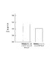
- FIG. 3 is a graph showing the results of verification of fatigue suppression by the hypersonic sound method, in which the response times obtained in the dual task test were averaged for a plurality of test subjects.
- the response time of the subject was about 750 msec in the pattern in which the vehicle sound and the dummy hypersonic sound were output from the speaker.
- the response time of the subject was approximately 740 msec. Therefore, it was confirmed that the response time was shortened by about 10 msec by outputting the hypersonic sound.
- the activation of nerve activity in the brain of the occupant exposed to hypersonic sound increases the amount of neurotransmitters consumed by the nerve activity, and after a long time, the nerve activity This may be due in part to the inability of the intracellular supply of transmitter to keep up.
- the inventors of the present invention have found that it is more effective to output the hypersonic sound only when the occupant is tired than to constantly output the hypersonic sound to the occupant. Got. Therefore, as in the occupant support device 1 according to the present embodiment, it is determined whether or not the occupant is easily fatigued based on the vehicle information. That is, control for operating the suppression unit 50 is performed.
- the vehicle information on the vehicle and the surroundings of the vehicle is acquired, and based on the vehicle information, the occupant is in a state of being easily fatigued. It is determined whether or not the occupant is easily fatigued, and when the occupant is determined to be in a state where the occupant is likely to be tired, a fatigue suppression unit which is mounted on the vehicle and suppresses occupant fatigue by activating the brainstem of the occupant of the vehicle is operated.
- the fatigue suppression unit may be operated. Good. If the fatigue-prone state lasts for less than a predetermined time such as momentary, it is considered that there is no shortage of neurotransmitters in the occupant's brain in the first place. Therefore, when the fatigue-prone state continues for a predetermined time, the unnecessary operation of the fatigue suppression unit can be suppressed by operating the fatigue suppression unit. As a result, a decrease in the effect of suppressing fatigue can be prevented.
- the physical load of the occupant is evaluated, and when the physical load is equal to or more than a predetermined load, it is determined that the occupant is in a state of being easily fatigued. It may be something. Focusing on the size of the physical load on the occupant as a condition for operating the fatigue suppressor, by evaluating the physical load, it is possible to accurately determine the timing of operating the fatigue suppressor, Unnecessary operation of the suppression unit can be suppressed. As a result, a decrease in the effect of suppressing fatigue can be prevented.
- the moving speed of the object in front or the side of the vehicle is acquired, It may be evaluated that the higher the moving speed of the object in front of or on the side of the vehicle, the greater the physical load. Since the information input to the occupant's vision increases as the moving speed of the object in front of or on the side of the vehicle increases, and the occupant is likely to be tired, the physical load is evaluated based on the moving speed of the object. Thus, it is possible to accurately determine the timing at which the fatigue suppression unit operates.
- the lane width of the lane in which the vehicle is traveling is evaluated based on the vehicle information, and the smaller the evaluated lane width, the lower the physical load. It may be evaluated as being large. Assess the physical load based on the lane width, as the narrower the lane in which the vehicle is traveling, the more visual information the occupant needs to process per unit time and the more likely it is that the occupant will be tired. Thereby, the timing for operating the fatigue suppression unit can be determined accurately.
- the road on which the vehicle is traveling is specified based on the vehicle position information included in the vehicle information, and the lane corresponding to the road is used as the road information.
- the lane width of the lane in which the vehicle is traveling may be obtained by reading out road information corresponding to the specified road with reference to the storage unit that stores at least the width. Since the lane width is obtained based on the road information, the physical load can be evaluated based on the accurate lane width. And the timing which operates a fatigue suppression part can be determined correctly.
- the distance between the vehicle and the object on the side of the vehicle is detected, and the smaller the detected distance is, the smaller the lane width is evaluated. It may be.
- the occupant perceives the distance to the object on the side of the vehicle, and the smaller the distance, the more occupant becomes nervous.Therefore, the occupant can accurately determine the physical condition of the occupant based on the distance to the object on the side of the vehicle.
- the load can be evaluated, and the timing for operating the fatigue suppression unit can be accurately determined.
- the brightness outside the vehicle may be detected, and the lower the detected brightness, the greater the physical load may be evaluated.
- the amount of information input to the occupant's vision is reduced, so that the occupant driving the vehicle tends to gaze to obtain more visual information, It is thought that it is easy to get tired.
- the slipperiness of the road surface of the lane on which the vehicle is traveling is detected, and the more the road surface is slippery, the greater the physical load is evaluated. It may be.
- the more slippery the road surface the more occupants tend to try to maintain their posture in line with the slip of the vehicle, and to acquire more acceleration, balance, and visual information as perceived by the semicircular canal, etc.
- At least one acceleration in the front-rear direction, the up-down direction, and the left-right direction of the vehicle is detected, and the larger the detected acceleration, the greater the physical load. It may be evaluated.
- a deviation or the like is likely to occur between the acceleration experienced by the semicircular canal and the movement of the vehicle, and the occupant tends to get sick. Therefore, it is considered that the occupant is easily tired.
- the change speed of the turning angle of the wheel provided in the vehicle is detected, and the larger the detected change speed, the greater the physical load is evaluated. It may be. If the change speed of the turning angle of the wheels provided in the vehicle is high, a deviation or the like is likely to occur between the acceleration felt by the semicircular canal and the movement of the vehicle, and the occupant tends to get sick. Therefore, it is considered that the occupant is easily tired.
- the fatigue suppression unit includes a first sound wave output unit that outputs a first sound wave having a frequency higher than a human audible sound range to the occupant,
- the first sound wave may be output to the occupant by the fatigue suppressing unit to activate the brainstem of the occupant.
- the fatigue suppression unit further includes a second sound wave output unit that outputs a second sound wave having a lower frequency than the first sound wave to the occupant.
- the first sound wave and the second sound wave may be simultaneously output to the occupant by the fatigue suppressing unit to activate the brainstem of the occupant.
- the sound environment can be brought into a state closer to a natural environment sound. As a result, it is possible to reduce the stress of the occupant, and it is possible to increase the effect of suppressing fatigue.
- the functions shown in the above-described embodiment can be implemented by one or a plurality of processing circuits.
- the processing circuit includes a programmed processing device such as a processing device including an electric circuit.
- Processors also include devices such as application specific integrated circuits (ASICs) or conventional circuit components arranged to perform the functions described in the embodiments.
- ASICs application specific integrated circuits
Landscapes
- Physics & Mathematics (AREA)
- General Physics & Mathematics (AREA)
- Traffic Control Systems (AREA)
Abstract
本発明の疲労抑制方法及び乗員支援装置は、車両および車両の周囲状況に関する車両情報に基づき、車両の乗員が疲労し易い状態であるか否かを判定し、乗員が疲労し易い状態であると判定された場合に、疲労抑制部を稼働させ、乗員の脳幹の活性化により乗員の疲労を抑制する。
Description
本発明は、疲労抑制方法及び乗員支援装置に関する。
特許文献1には、可聴音と超高周波音を組み合わせたハイパーソニックサウンドを人間に印加して、人間の脳幹・視床・視床下部を含む基幹脳及び基幹脳ネットワーク系を活性化して脳活性化効果を導くための振動体が提案されている。
しかしながら、特許文献1に記載の技術は、ハイパーソニックサウンドを人間に印加し続けるものであるため、車両の乗員に対して使用する際に脳活性化効果が十分に得られない場合が生じうるという問題があった。
本発明は、上記問題に鑑みてなされたものであり、その目的とするところは、車両の乗員が疲労し易い状況において、脳活性化効果を十分に得ることが可能な疲労抑制方法及び乗員支援装置を提供することにある。
上述した課題を解決するために、本発明の一態様に係る疲労抑制方法及び乗員支援装置によれば、車両および車両の周囲状況に関する車両情報に基づき、車両の乗員が疲労し易い状態であるか否かを判定し、乗員が疲労し易い状態であると判定された場合に、疲労抑制部を稼働させ、乗員の脳幹の活性化により乗員の疲労を抑制する。
本発明によれば、車両運転中に、乗員が疲労し易い状況が継続する場合であっても、脳活性化効果を十分に得ることができる。
次に、図面を参照して、本発明の実施の形態を詳細に説明する。説明において、同一のものには同一符号を付して重複説明を省略する。
[乗員支援装置の構成]
図1は、本実施形態に係る乗員支援装置の構成を示すブロック図である。図2は、本実施形態に係る乗員支援装置による疲労抑制処理の手順を示すフローチャートである。
図1は、本実施形態に係る乗員支援装置の構成を示すブロック図である。図2は、本実施形態に係る乗員支援装置による疲労抑制処理の手順を示すフローチャートである。
図1に示すように、乗員支援装置1は、処理部100(コントローラ)と、疲労抑制部50とを、備えている。乗員支援装置1は、図示しない車両に搭載され、処理部100は、当該車両に搭載された車載センサ90、及び、疲労抑制部50と通信可能なように接続される。
車載センサ90は、車両に搭載された、レーザレーダやミリ波レーダ、カメラなど、車両の周囲に存在する物体を検出する物体検出センサなどからなる。車載センサ90は、複数の異なる種類の物体検出センサを備えるものであってもよい。
車載センサ90は、車両の周囲の環境を検出する。例えば、車載センサ90は、他車両、バイク、自転車、歩行者を含む移動物体、及び停止車両を含む静止物体を検出し、移動物体及び静止物体の車両に対する位置、姿勢、大きさ、速度、加速度、減速度、ヨーレートなどを検出するものであってもよい。車載センサ90は、検出結果として、例えば車両の上方の空中から眺めた天頂図(平面図ともいう)における、2次元の物体の挙動を出力するものであってもよい。また、車載センサ90は、車両の周囲に存在する標識(道路標識や路面表示された標識)やガイドレール等を検出するものであってもよい。その他にも、車載センサ90は、車両が備える車輪の回転速度や回転速度差を検出して、車両が走行している車線の路面の滑りやすさを検出するものであってもよい。
また、車載センサ90は、車両の周囲の環境の他にも、車両の状態を検出する。例えば、車載センサ90は、車両の移動速度(前後方向、左右方向の移動速度、旋回速度)や、車両が備える車輪の転舵角、転舵角の変化速度を検出するものであってもよい。
処理部100は、車載センサ90による検出結果に基づいて、疲労抑制部50を制御する。
処理部100(制御部またはコントローラの一例)は、CPU(中央処理装置)、メモリ、及び入出力部を備える汎用のマイクロコンピュータである。処理部100には、乗員支援装置の一部として機能させるためのコンピュータプログラム(乗員支援プログラム)がインストールされている。コンピュータプログラムを実行することにより、処理部100は、乗員支援装置が備える複数の情報処理回路(10、20、30)として機能する。
なお、ここでは、ソフトウェアによって運転支援装置が備える複数の情報処理回路(10、20、30)を実現する例を示す。ただし、以下に示す各情報処理を実行するための専用のハードウェアを用意して、情報処理回路(10、20、30)を構成することも可能である。また、複数の情報処理回路(10、20、30)を個別のハードウェアにより構成してもよい。更に、情報処理回路(10、20、30)は、車両にかかわる他の制御に用いる電子制御ユニット(ECU)と兼用してもよい。
処理部100は、複数の情報処理回路(10、20、30)として、取得部10と、負荷評価部20と、環境判定部30とを備える。
取得部10は、車載センサ90によって検出された車両情報(車両の周囲の環境に関する情報、及び、車両の状態に関する情報)のうち、乗員の身体的負荷の評価に必要な車両情報を抽出、又は、保存し、乗員の身体的負荷の評価に必要な車両情報を負荷評価部20に送信する。
乗員の身体的負荷の評価に必要な情報として、例えば、車両の移動速度(前後方向、左右方向の移動速度、旋回速度)、車両の前方もしくは側方の物体の移動速度、車両が走行している車線の車線幅、車両の側方の物体との間の距離、車両の外部の明度、車両が走行している車線の路面の滑りやすさ、車両の前後方向の加速度、上下方向の加速度、左右方向の加速度、車両が備える車輪の転舵角の変化速度、などが挙げられる。
なお、取得部10が負荷評価部20に送信する車両情報は、上記に示した情報の一部であってもよいし、乗員の身体的負荷の評価に用いるものであれば、上記に示した情報に限定されない。
また、取得部10が負荷評価部20に送信する車両情報は、車載センサ90によって取得した車両情報に限定されない。例えば、乗員支援装置1は、道路情報として道路に対応した車線幅を少なくとも記憶する記憶部を更に有するものであってもよく、取得部10は、当該記憶部に記憶された道路情報に基づいて取得した、車両が走行している車線の車線幅を、負荷評価部20に送信するものであってもよい。
より具体的には、取得部10は、車両情報に含まれる車両の位置情報に基づいて、車両が走行している道路を特定し、記憶部を参照して、特定した道路に対応する道路情報を読み出すものであってもよい。道路情報を読み出すことにより、取得部10は、特定した道路における、車両が走行している車線の車線幅を取得することができる。
負荷評価部20は、取得部10から送信された車両情報に基づき、乗員の身体的負荷を評価する。例えば、取得部10から送信された車両情報に基づいて、乗員の身体的負荷の大きさの尺度となる評価値を算出する。評価値の算出方法は、1種類の方法を使用するものであってもよいし、複数種類の方法を使用して、異なる種類の、複数の評価値を算出するものであってもよい。乗員の身体的負荷の大きさの尺度となる評価値の算出方法については後述する。
環境判定部30は、取得部10から送信された車両情報、あるいは、負荷評価部20によって算出された乗員の身体的負荷の大きさに基づいて、乗員が疲労し易い状態であるか否かを判定する。より具体的には、負荷評価部20にて評価した身体的負荷が所定負荷以上である場合(あるいは算出した評価値が所定の閾値以上である場合)に、乗員が疲労し易い状態であると判定する。
なお、環境判定部30は、負荷評価部20にて評価した身体的負荷が所定負荷以上である場合(あるいは算出した評価値が所定の閾値以上である場合)が、所定時間以上継続する場合に、乗員が疲労し易い状態であると判定するものであってもよい。
ここで、判定に使用する所定時間は、乗員からの指示に基づいて決定されるものであってもよいし、乗員が運転する場合における手動運転の特性といった、乗員の個人差に合わせて決定されるものであってもよい。
さらに、負荷評価部20にて複数の評価値が算出される場合、環境判定部30は、複数の評価値のうちの一部または全部が所定の閾値を超えたことをもって、乗員が疲労し易い状態であると判定するものであってもよい。
または、複数の評価値を重みづけ平均して得られる平均評価値が所定の閾値を超えたことをもって、乗員が疲労し易い状態であると判定するものであってもよい。ここで、複数の評価値のうちの各評価値に対する重みづけは、乗員の身体的負荷と各評価値との間の相関関係の度合いに基づいて決定される。このように、複数の評価値を重みづけ平均して得られる平均評価値を用いることにより、乗員が疲労し易い状態であるか否かの判定をより正確に行うことができる。
疲労抑制部50は、処理部100からの指令に基づき、乗員の脳幹の活性化を引き起こす非侵襲的な方法を実行し、脳幹の活性化を介して乗員の疲労を抑制する。
疲労抑制部50によって行う、乗員の脳幹の活性化をもたらす非侵襲的な方法としては、例えば、経頭蓋磁気刺激法(TMS)、経頭蓋直流電気刺激法(tDCS)、経頭蓋的集束超音波法(tFUS)、ハイパーソニックサウンド法などによる方法が挙げられる。疲労抑制部50は、これらの方法のうち少なくとも一つを用いて、乗員の脳幹の活性化を実現する。疲労抑制部50は、これらの方法を組み合わせて、乗員の脳幹の活性化を実現するものであってもよい。
ここで、経頭蓋磁気刺激法(TMS)とは、電磁石によって生み出される急激な磁場の変化によって脳の組織内に誘起される電流によって脳を刺激する方法である。経頭蓋直流電気刺激法(tDCS)とは、乗員の頭部、または脊髄神経に対して極めて微弱な直流電気を流して脳を刺激する方法である。経頭蓋的集束超音波法(tFUS)とは、脳内で収束する超音波を利用して、音圧によって脳を刺激する方法である。
また、ハイパーソニックサウンド法とは、人間の可聴音域よりも高い周波数の超音波(ハイパーソニックサウンド)を乗員に対して出力し、乗員の脳幹の活性化を実現する方法である。ハイパーソニックサウンド法によって出力されるハイパーソニックサウンドの好ましい周波数帯域は、少なくとも32kHz以上の周波数帯域であり、好ましくは48kHz以上の周波数帯域である。さらに、より好ましくは80kHz以上かつ88kHz以下の周波数帯域である。
ハイパーソニックサウンド法は、人間の可聴音域よりも高い周波数の超音波を出力可能なスピーカーなど、乗員に対して非接触な装置によって実現可能である点で、経頭蓋磁気刺激法(TMS)、経頭蓋直流電気刺激法(tDCS)、経頭蓋的集束超音波法(tFUS)などと比較して優れている。また、ハイパーソニックサウンド法は、電場や磁場ではなく音波を利用するため、車載の周辺機器への影響が抑えられる点で優れている。
ハイパーソニックサウンド法によって脳幹の活性化が実現される原理には不明な点も多いが、都市の環境音に上述した周波数帯域にある超音波の成分がほとんど含まれないのに対し、熱帯雨林などの自然環境音には当該超音波の成分が多く含まれることから、ハイパーソニックサウンド法によって作り出される超音波によって自然環境音に近い状態が作り出され、その結果、都市生活で人間が受けているストレスが軽減されるといった形で、脳の活動状態に影響を及ぼしている可能性がある。実際、ハイパーソニックサウンド法による超音波を含む音を浴びた人間の脳内で血流量が増加するなどして、リラックス状態を示すとされるα波が脳波に現れるという効果が生じる。
以下、本実施形態では、疲労抑制部50は、ハイパーソニックサウンド法を実行するものとして説明する。
図1に示すように、本実施形態において疲労抑制部50は、人間の可聴音域よりも高い周波数の第1音波を発生可能な第1音波出力部51を備えている。また、疲労抑制部50は、第1音波よりも低い周波数の第2音波を乗員に対して出力する第2音波出力部53を備えるものであってもよい。
なお、乗員支援装置1とは別途設けられる車載のスピーカーがハイパーソニックサウンド法で出力される超音波を出力可能なものであれば、当該スピーカーを第1音波出力部51として使用するものであってもよい。
上述した第1音波出力部51から出力される第1音波、及び、第2音波出力部53から出力される第2音波は、それぞれ一つの周波数成分に限定されるものではなく、複数の周波数成分を含むものであってもよいし、さらには、第1音波及び第2音波の周波数成分のパターンが、時間変動するものであってもよい。
[負荷評価の方法]
次に、負荷評価部20において実行する、乗員の身体的負荷の大きさの尺度となる評価値(以下、評価値)の算出方法については説明する。なお、負荷評価部20は、以下で例示されるような算出方法を、少なくとも一つを実行する。また、負荷評価部20は、複数の算出方法を実行するものであってもよい。
次に、負荷評価部20において実行する、乗員の身体的負荷の大きさの尺度となる評価値(以下、評価値)の算出方法については説明する。なお、負荷評価部20は、以下で例示されるような算出方法を、少なくとも一つを実行する。また、負荷評価部20は、複数の算出方法を実行するものであってもよい。
(第1算出方法)
「第1算出方法」として、負荷評価部20は、車両の移動速度(前後方向、左右方向の移動速度、旋回速度)が大きいほど評価値を大きく算出する(すなわち、乗員の身体的負荷が大きいと評価する)。このように算出する理由は、車両の移動速度が大きいほど、乗員の視覚に入力される情報が増えることを考慮したからである。その結果、乗員は疲れやすくなることから、車両の移動速度が大きい状況は、乗員の身体的負荷が大きい状況であると考えられるためである。
「第1算出方法」として、負荷評価部20は、車両の移動速度(前後方向、左右方向の移動速度、旋回速度)が大きいほど評価値を大きく算出する(すなわち、乗員の身体的負荷が大きいと評価する)。このように算出する理由は、車両の移動速度が大きいほど、乗員の視覚に入力される情報が増えることを考慮したからである。その結果、乗員は疲れやすくなることから、車両の移動速度が大きい状況は、乗員の身体的負荷が大きい状況であると考えられるためである。
具体的には、パラメータxについての単調増加関数f1(x)を用意し、車両の移動速度の「大きさ」をパラメータxに代入した際の単調増加関数f1(x)の値を評価値として採用する。
また、車両の移動速度が0以上の場合と、移動速度が負の場合とで、異なる単調増加関数f1(x)を用いて評価値を算出するものであってもよい。これは、移動速度が車両の前後方向の移動速度である場合に、車両を前進させる状況と、後進させる状況とでは、乗員が感じる身体的負荷の度合いも異なると考えられるからである。
さらに、単調増加関数f1(x)としては、種々の関数形を採用することが可能である。なお、単調増加関数f1(x)は、パラメータxに応じて乗員が感じる身体的負荷の大きさを示すものであるため、パラメータxが大きくなればなるほど、パラメータxの単位増加量あたりの単調増加関数f1(x)の増加量は、小さくなると考えられる。これは、身体的ストレスについての限界効用逓減の性質を表すものである。
したがって、単調増加関数であって、パラメータxについての2回微分が負の値になるような関数(例えば対数関数)を、単調増加関数f1(x)として採用してもよい。
(第2算出方法)
「第2算出方法」として、負荷評価部20は、車両の前方もしくは側方の物体の移動速度が大きいほど、評価値を大きく算出する(すなわち、乗員の身体的負荷が大きいと評価する)。このように算出する理由は、車両の前方もしくは側方の物体の移動速度が大きいほど、乗員の視覚に入力される情報が増えることを考慮したからである。その結果、乗員は疲れやすくなることから、車両の前方もしくは側方の物体の移動速度が大きい状況は、乗員の身体的負荷が大きい状況であると考えられるためである。
「第2算出方法」として、負荷評価部20は、車両の前方もしくは側方の物体の移動速度が大きいほど、評価値を大きく算出する(すなわち、乗員の身体的負荷が大きいと評価する)。このように算出する理由は、車両の前方もしくは側方の物体の移動速度が大きいほど、乗員の視覚に入力される情報が増えることを考慮したからである。その結果、乗員は疲れやすくなることから、車両の前方もしくは側方の物体の移動速度が大きい状況は、乗員の身体的負荷が大きい状況であると考えられるためである。
具体的には、「第1算出方法」で説明した単調増加関数f1(x)と同様に、単調増加関数f2(x)を用意し、車両の前方もしくは側方の物体の移動速度の「大きさ」をパラメータxに代入した際の単調増加関数f2(x)の値を評価値として採用する。
ここで、車両の前方もしくは側方の物体の移動速度を取得するため、車載センサ90は撮像部を含む場合に、取得部10は、撮像部によって撮像した画像から、車両の前方もしくは側方の物体の移動速度を取得するものであってもよい。撮像した画像から得られた、車両の前方もしくは側方の物体の移動速度は、取得部10から負荷評価部20に送信され、評価値の算出に用いられるものであってもよい。
また、車両の前方もしくは側方の物体の移動速度が0以上の場合と、負の場合とで、異なる単調増加関数f2(x)を用いて評価値を算出するものであってもよいし、さらには、単調増加関数f2(x)としては、種々の関数形を採用することが可能である。
(第3算出方法)
「第3算出方法」として、負荷評価部20は、車両が走行している車線の車線幅が狭いほど、評価値を大きく算出する(すなわち、乗員の身体的負荷が大きいと評価する)。このように算出する理由は、車両が走行している車線の車線幅が狭いほど、乗員が単位時間当たりの処理すべき視覚情報が増加することを考慮したからである。特に、乗員が運転を行う場合には、乗員は隣接車線に対する警戒をする必要があるため、処理すべき視覚情報が増加する。その結果、乗員は疲れやすくなることから、車両が走行している車線の車線幅が狭い状況は、乗員の身体的負荷が大きい状況であると考えられるためである。
「第3算出方法」として、負荷評価部20は、車両が走行している車線の車線幅が狭いほど、評価値を大きく算出する(すなわち、乗員の身体的負荷が大きいと評価する)。このように算出する理由は、車両が走行している車線の車線幅が狭いほど、乗員が単位時間当たりの処理すべき視覚情報が増加することを考慮したからである。特に、乗員が運転を行う場合には、乗員は隣接車線に対する警戒をする必要があるため、処理すべき視覚情報が増加する。その結果、乗員は疲れやすくなることから、車両が走行している車線の車線幅が狭い状況は、乗員の身体的負荷が大きい状況であると考えられるためである。
具体的には、パラメータxについての単調減少関数g1(x)を用意し、車線の車線幅をパラメータxに代入した際の単調減少関数g1(x)の値を評価値として採用する。
単調減少関数g1(x)としては、種々の関数形を採用することが可能である。車線幅が大きいほど、隣接車線を走行する車両との接触の可能性は低くなるため、乗員は比較的安心して過ごすことができることから、乗員の身体的負荷も小さくなる。
もっとも、車線幅が十分な大きさ以上になれば、乗員が感じる身体的負荷はそれほど変化しないものと考えられる。したがって、単調減少関数であって、パラメータxの値が所定の値以上である場合に、一定の値に収束するような関数(例えば、パラメータxに反比例する関数)を、単調減少関数g1(x)として採用してもよい。
なお、取得部10において、車両情報に基づいて車両が走行している車線の車線幅を評価するものであってもよい。評価された車線の車線幅は、取得部10から負荷評価部20に送信され、評価値の算出に用いられるものであってもよい。
車両が走行している車線の車線幅を評価には、種々の方法が考えられる。例えば、取得部10は、車両情報に含まれる車両の位置情報に基づいて、車両が走行している道路を特定し、道路情報として道路に対応した車線幅を少なくとも記憶する記憶部(図示なし)を参照して、特定した道路に対応する道路情報を読み出すものであってもよい。道路情報を読み出すことにより、取得部10は、特定した道路における、車両が走行している車線の車線幅を取得することができる。
また、取得部10は、車載センサ90によって検出された、車両と車両の側方の物体との間の距離に基づき、当該距離が小さいほど、車線幅が小さいと評価するものであってもよい。
(第4算出方法)
「第4算出方法」として、負荷評価部20は、車両の外部の明度が低いほど、評価値を大きく算出する(すなわち、乗員の身体的負荷が大きいと評価する)。このように算出する理由は、夜間など、車両の外部が暗い場合には、乗員の視覚に入力される情報量が減るため、車両を運転する乗員にとっては、より多くの視覚情報を得ようと注視するようになる傾向があることを考慮したからである。
「第4算出方法」として、負荷評価部20は、車両の外部の明度が低いほど、評価値を大きく算出する(すなわち、乗員の身体的負荷が大きいと評価する)。このように算出する理由は、夜間など、車両の外部が暗い場合には、乗員の視覚に入力される情報量が減るため、車両を運転する乗員にとっては、より多くの視覚情報を得ようと注視するようになる傾向があることを考慮したからである。
具体的には、「第3算出方法」で説明した単調減少関数g1(x)と同様に、単調減少関数g2(x)を用意し、車両の外部の明度をパラメータxに代入した際の単調減少関数g2(x)の値を評価値として採用する。単調減少関数g2(x)としては、種々の関数形を採用することが可能である。
(第5算出方法)
「第5算出方法」として、負荷評価部20は、車両が走行している車線の路面の滑りやすさに基づいて、路面が滑りやすいほど、評価値を大きく算出する(すなわち、乗員の身体的負荷が大きいと評価する)。このように算出する理由は、路面が滑りやすいほど、乗員は車両の滑りに合わせて体勢を維持しようとし、三半規管などで体感する加速度や、平衡感覚、視覚情報をより多く取得しようとする傾向があることを考慮したからである。さらには、車両を運転する乗員にとっては、滑りやすい路面を走行する際には、安定した運転制御を保つために、三半規管などで体感する体感する加速度や、平衡感覚、視覚情報をより多く取得しようとする傾向があることを考慮したからである。
「第5算出方法」として、負荷評価部20は、車両が走行している車線の路面の滑りやすさに基づいて、路面が滑りやすいほど、評価値を大きく算出する(すなわち、乗員の身体的負荷が大きいと評価する)。このように算出する理由は、路面が滑りやすいほど、乗員は車両の滑りに合わせて体勢を維持しようとし、三半規管などで体感する加速度や、平衡感覚、視覚情報をより多く取得しようとする傾向があることを考慮したからである。さらには、車両を運転する乗員にとっては、滑りやすい路面を走行する際には、安定した運転制御を保つために、三半規管などで体感する体感する加速度や、平衡感覚、視覚情報をより多く取得しようとする傾向があることを考慮したからである。
具体的には、「第1算出方法」で説明した単調増加関数f1(x)と同様に、単調増加関数f3(x)を用意し、車両が走行している車線の路面の滑りやすさを示す指標値をパラメータxに代入した際の単調増加関数f3(x)の値を評価値として採用する。
路面の滑りやすさを示す指標値としては、例えば、車両が備える車輪の、車輪間での回転速度差や、車両外部の静止物体(信号機、交通標識など)との相対速度として得られる実際の車両の車速と車輪速度の間の速度差、などを用いることができる。その他、路面の状態(濡れた路面か否か、雪道であるか否か)などを数値化して得られる指標値を用いるものであってもよい。
(第6算出方法)
「第6算出方法」として、負荷評価部20は、車両の前後方向、上下方向、左右方向の少なくとも一つの加速度に基づいて、当該加速度が大きいほど、評価値を大きく算出する(すなわち、乗員の身体的負荷が大きいと評価する)。このように算出する理由は、悪路や曲がりくねった道路を走行する場合には、三半規管などで体感する加速度と車両の動きとの間で偏差などが生じやすく、乗員は車酔いしやすいことを考慮したからである。
「第6算出方法」として、負荷評価部20は、車両の前後方向、上下方向、左右方向の少なくとも一つの加速度に基づいて、当該加速度が大きいほど、評価値を大きく算出する(すなわち、乗員の身体的負荷が大きいと評価する)。このように算出する理由は、悪路や曲がりくねった道路を走行する場合には、三半規管などで体感する加速度と車両の動きとの間で偏差などが生じやすく、乗員は車酔いしやすいことを考慮したからである。
具体的には、「第1算出方法」で説明した単調増加関数f1(x)と同様に、単調増加関数f4(x)を用意し、車両の前後方向、上下方向、左右方向の少なくとも一つの加速度の大きさをパラメータxに代入した際の単調増加関数f4(x)の値を評価値として採用する。
また、加速度の大きさをパラメータxに代入する代わりに、加速度の変化率の大きさをパラメータxに代入した際の単調増加関数f4(x)の値を評価値として採用してもよい。加速度の変化が大きいほど、乗員に作用する力が大きく変動していることを意味し、乗員の身体的負荷はそれだけ大きいと考えられるからである。
(第7算出方法)
「第7算出方法」として、負荷評価部20は、車両が備える車輪の転舵角の変化速度が大きいほど、評価値を大きく算出する(すなわち、乗員の身体的負荷が大きいと評価する)。このように算出する理由は、悪路や曲がりくねった道路を走行する場合などで車両が備える車輪の転舵角の変化速度が大きい場合には、三半規管などで体感する加速度と車両の動きとの間で偏差などが生じやすく、乗員は車酔いしやすいことを考慮したからである。
「第7算出方法」として、負荷評価部20は、車両が備える車輪の転舵角の変化速度が大きいほど、評価値を大きく算出する(すなわち、乗員の身体的負荷が大きいと評価する)。このように算出する理由は、悪路や曲がりくねった道路を走行する場合などで車両が備える車輪の転舵角の変化速度が大きい場合には、三半規管などで体感する加速度と車両の動きとの間で偏差などが生じやすく、乗員は車酔いしやすいことを考慮したからである。
「第6算出方法」の場合と同様に、単調増加関数f5(x)を用意し、車両が備える車輪の転舵角の変化速度の大きさをパラメータxに代入した際の単調増加関数f5(x)の値を評価値として採用する。
[乗員支援装置の処理手順]
次に、本実施形態に係る乗員支援装置1による疲労抑制処理の手順を、図2のフローチャートを参照して説明する。
次に、本実施形態に係る乗員支援装置1による疲労抑制処理の手順を、図2のフローチャートを参照して説明する。
図2に示す処理は、車両のイグニッションがオンされると開始され、イグニッションがオンとなっている間、繰り返し実行される。又は、図示しない切り替えスイッチ等により、乗員から疲労抑制処理の実行が指定されると開始され、疲労抑制処理の実行が指定されている間、繰り返し実行される。
まず、ステップS101において、取得部10は、車載センサ90によって検出された車両情報を取得する。取得部10は、車両情報を負荷評価部20に送信する。
ステップS103において、負荷評価部20は、取得部10から送信された車両情報に基づき、乗員の身体的負荷を評価する。具体的には、乗員の身体的負荷の大きさの尺度となる評価値を算出する。
ステップS105において、環境判定部30は、取得部10から送信された車両情報、あるいは、負荷評価部20によって算出された乗員の身体的負荷の大きさに基づいて、乗員が疲労し易い状態であるか否かを判定する。より具体的には、負荷評価部20にて評価した身体的負荷が所定負荷以上である場合(あるいは算出した評価値が所定の閾値以上である場合)に、乗員が疲労し易い状態であると判定する。
ステップS107において、環境判定部30は、疲労し易い状態が所定時間以上継続しているか否かを判定する。
具体的には、環境判定部30は、内蔵されたタイマー等により、ステップS105にて疲労し易い状態ではないと判定された後、最初に疲労し易い状態であると判定されたタイミングからの時間を計測し、計測した時間が、所定時間以上であるか否かを判定する。
そして、疲労し易い状態が所定時間以上継続していると判定された場合(ステップS107でYESの場合)、ステップS109に進み、処理部100は、疲労抑制部50を起動させる。一方、疲労し易い状態が所定時間以上継続していると判定されない場合(ステップS107でNOの場合)、ステップS113に進み、処理部100は、疲労抑制部50を停止させる。
なお、ステップS107は省略されてもよい。ステップS107を省略する場合、ステップS105にて疲労し易い状態と判定された場合にステップS109に進み、それ以外の場合には、ステップS113に進む。
ステップS109、又は、ステップS113の処理を実行した後、図2のフローチャートは終了する。
[ハイパーソニックサウンドによる疲労抑制]
次に、疲労抑制部50によって実行されるハイパーソニックサウンド法の効果について説明する。
次に、疲労抑制部50によって実行されるハイパーソニックサウンド法の効果について説明する。
ハイパーソニックサウンド法による疲労抑制の効果を検証するため、発明者らは、車両の乗員が置かれる環境を模すため、スピーカーによって発生させた車両音(車両走行時のロードノイズ)が存在する状況下の被験者に対し、二重タスク試験を行った。二重タスク試験として、被験者は、モニタ画面の中央に表示される数字を暗算で加算し続けていくというタスク(暗算タスク)を行いながら、同時に、モニタ画面の隅に配置したランプが点灯したらボタンを押すというタスク(点灯反応タスク)を行った。
発明者らは、スピーカーから車両音と超高周波音(超音波)を含まない可聴音であるダミーのハイパーソニックサウンドとを出力するパターンと、車両音と超高周波を含む音(超音波)であるハイパーソニックサウンド(ダミーのハイパーソニックサウンドにおける可聴音と超高周波音とで形成された音)とを出力するパターンの、2つのパターンにおいて、ランプが点灯してから被験者がボタンを押すまでのレスポンス時間を計測した。
なお、上記の二重タスクは、例えば、乗員が運転して車両の前方を注視しつつ、周辺視野で、車両の側方を注意したり、車両の走行に合わせて体勢を維持したりする状況に相当する。もしくは、車室内にいる乗員が、読書やインターネットをしている状況で、車両の走行に合わせて体勢を維持するような状況に相当する。
走行中の車両にいる乗員の疲労は、運転への集中以外にも、車両の運動に合わせて身体の平衡感覚を保とうとする脳幹の無意識的な働きによっても生じる。このように、乗員の疲労は、筋肉の疲労というよりも、むしろ脳の疲労というべきものである。
脳が疲労する結果、刺激に対する反応が遅れることが予想されるため、上記のような二重タスクにおいて、ハイパーソニックサウンドを出力する場合にレスポンス時間が短縮されることが確認できれば、疲労抑制の効果が生じていると結論できる。
発明者らは、複数の被験者(12人)に対して、以下の条件での試験を行い、レスポンス時間を測定した。
各被験者に対して、脳神経反応に影響する被験者の疲労、睡眠、服薬、カフェイン取得状況等を確認するためのバックグラウンド・アンケートを行い、その後、所定の練習時間を与えて、暗算タスク及び点灯反応タスクに慣れてもらった。以上の準備が終わった後に、各被験者には上記の二重タスク(計9セット)を行ってもらった。なお、被験者間での差が生じないよう、アンケート、練習時間、二重タスクの実施条件には差が生じないよう注意した。
なお、二重タスク実施中の、ハイパーソニックサウンドの出力のタイミングに関しては、音を受容してから疲労抑制効果が得られるまで数分を要するため、二重タスクのセット開始の1分前から再生することとした。各被験者が行う複数セットの二重タスクのうち、いずれのセットでハイパーソニックサウンドを出力するかはランダムに設定した。そして、プラセボ効果を回避するため、どのセットでハイパーソニックサウンドが出力されるのかは被験者に伝えないこととした(単盲験法)。
図3は、ハイパーソニックサウンド法による疲労抑制の検証結果を示すグラフ図であり、二重タスク試験において得られたレスポンス時間について、複数の被験者の測定結果の平均をとったものである。
図3に示されるように、スピーカーから車両音とダミーのハイパーソニックサウンドとを出力するパターンでは、被験者のレスポンス時間はおおよそ750msec程度であった。一方、スピーカーから車両音とハイパーソニックサウンドの両方を出力するパターンでは、被験者のレスポンス時間はおおよそ740msec程度であった。したがって、ハイパーソニックサウンドの出力によって、10数msec程度、レスポンス時間が短縮されることが確認された。
[ハイパーソニックサウンドによる疲労抑制と出力時間の関係]
上述の二重タスク試験の結果が示すように、ハイパーソニックサウンドの出力は乗員の疲労抑制の効果を生じさせる。しかしながら、乗員に対してハイパーソニックサウンドを常に出力し続けた場合、疲労抑制の効果は弱まる傾向がある。
上述の二重タスク試験の結果が示すように、ハイパーソニックサウンドの出力は乗員の疲労抑制の効果を生じさせる。しかしながら、乗員に対してハイパーソニックサウンドを常に出力し続けた場合、疲労抑制の効果は弱まる傾向がある。
この原因は不明であるが、ハイパーソニックサウンドを浴びた乗員の脳内での神経活動が活発化する結果、神経活動によって神経伝達物質が消費される量が増加し、長時間経過後には、神経伝達物質の細胞内での供給が、追いつかなくなってしまうことに一因がある可能性がある。
そのため、本発明の発明者らは、乗員に対してハイパーソニックサウンドを常に出力し続けるよりも、乗員が疲れ易い状況になったときにのみ、ハイパーソニックサウンドを出力することが有効であるという知見を得た。そこで、本実施形態の乗員支援装置1のように、車両情報に基づき、乗員が疲労し易い状態であるか否かを判定し、乗員が疲労し易い状態であると判定された場合に、疲労抑制部50を稼働させる制御を行うことにしたのである。
[実施形態の効果]
以上詳細に説明したように、本実施形態に係る疲労抑制方法及び乗員支援装置によれば、車両および車両の周囲状況に関する車両情報を取得し、車両情報に基づき、乗員が疲労し易い状態であるか否かを判定し、乗員が疲労し易い状態であると判定された場合に、車両に搭載され、車両の乗員の脳幹の活性化により乗員の疲労を抑制する疲労抑制部を稼働させる。
以上詳細に説明したように、本実施形態に係る疲労抑制方法及び乗員支援装置によれば、車両および車両の周囲状況に関する車両情報を取得し、車両情報に基づき、乗員が疲労し易い状態であるか否かを判定し、乗員が疲労し易い状態であると判定された場合に、車両に搭載され、車両の乗員の脳幹の活性化により乗員の疲労を抑制する疲労抑制部を稼働させる。
これにより、乗員の疲れを抑制する必要があるタイミングにおいて、疲労抑制部を稼働させて乗員の脳幹を活性化するので、神経伝達物質の不足などに起因した疲労抑制効果の低下を防ぐことができる。さらには、乗員の疲れを抑制する必要がないタイミングでは、疲労抑制部を稼働させる必要がないため、不必要なタイミングでの乗員の脳幹の活性化が抑止され、代わりに、疲れ易い状況において、乗員はスムーズに外界の変化に対応できるようになる。結果として、乗員が車両に乗っている期間全体でみたときの、疲労抑制効果の低下を防止できる。
また、本実施形態に係る疲労抑制方法及び乗員支援装置によれば、所定時間以上継続して乗員が疲労し易い状態であると判定された場合に、疲労抑制部を稼働させるものであってもよい。疲労し易い状態が瞬間的であるような、所定時間未満しか継続しない場合には、そもそも、乗員の脳内での神経伝達物質の不足は発生しないと考えられる。そのため、疲労し易い状態が所定時間継続した場合に、疲労抑制部を稼働させることで、疲労抑制部の不必要な稼働を抑制することができる。その結果、疲労抑制効果の低下を防止できる。
さらに、本実施形態に係る疲労抑制方法及び乗員支援装置によれば、乗員の身体的負荷を評価し、身体的負荷が所定負荷以上である場合に、乗員が疲労し易い状態であると判定するものであってもよい。疲労抑制部を稼働させるための条件として、乗員の身体的負荷の大きさに着目し、身体的負荷を評価することで、疲労抑制部を稼働させるタイミングを正確に決定することができるため、疲労抑制部の不必要な稼働を抑制することができる。その結果、疲労抑制効果の低下を防止できる。
また、本実施形態に係る疲労抑制方法及び乗員支援装置によれば、車両の移動速度が大きいほど、身体的負荷が大きいと評価するものであってもよい。車両の移動速度が大きいほど、乗員の視覚に入力される情報が増え、乗員は疲れやすくなると考えられるため、車両の移動速度に基づいて身体的負荷を評価することにより、疲労抑制部を稼働させるタイミングを正確に決定することができる。
さらに、本実施形態に係る疲労抑制方法及び乗員支援装置によれば、車両の前方もしくは側方を撮像する撮像部によって撮像した画像から、車両の前方もしくは側方の物体の移動速度を取得し、車両の前方もしくは側方の物体の移動速度が大きいほど、身体的負荷が大きいと評価するものであってもよい。車両の前方もしくは側方の物体の移動速度が大きいほど、乗員の視覚に入力される情報が増え、乗員は疲れやすくなると考えられるため、物体の移動速度に基づいて身体的負荷を評価することにより、疲労抑制部を稼働させるタイミングを正確に決定することができる。
また、本実施形態に係る疲労抑制方法及び乗員支援装置によれば、車両情報に基づいて、車両が走行している車線の車線幅を評価し、評価した車線幅が狭いほど、身体的負荷が大きいと評価するものであってもよい。車両が走行している車線の車線幅が狭いほど、乗員が単位時間当たりの処理すべき視覚情報が増加し、乗員は疲れやすくなると考えられるため、車線幅に基づいて身体的負荷を評価することにより、疲労抑制部を稼働させるタイミングを正確に決定することができる。
さらに、本実施形態に係る疲労抑制方法及び乗員支援装置によれば、車両情報に含まれる車両の位置情報に基づいて、車両が走行している道路を特定し、道路情報として道路に対応した車線幅を少なくとも記憶する記憶部を参照して、特定した道路に対応する道路情報を読み出すことで、車両が走行している車線の車線幅を取得するものであってもよい。道路情報に基づいて車線幅を取得するため、正確な車線幅に基づいて身体的負荷を評価することができる。そして、疲労抑制部を稼働させるタイミングを正確に決定することができる。
また、本実施形態に係る疲労抑制方法及び乗員支援装置によれば、車両と車両の側方の物体との間の距離を検出し、検出した距離が小さいほど、車線幅が小さいと評価するものであってもよい。乗員は車両の側方の物体との距離を知覚して、当該距離が小さいほど乗員は緊張を増すため、乗員は車両の側方の物体との距離に基づくことにより、正確に乗員の身体的負荷を評価することができる、そして、疲労抑制部を稼働させるタイミングを正確に決定することができる。
さらに、本実施形態に係る疲労抑制方法及び乗員支援装置によれば、車両の外部の明度を検出し、検出した明度が低いほど、身体的負荷が大きいと評価することものであってもよい。車両の外部の明度が低いほど、乗員の視覚に入力される情報量が減るため、車両を運転する乗員にとっては、より多くの視覚情報を得ようと注視するようになる傾向があり、乗員は疲れやすくなると考えられる。
したがって、車両の外部の明度に基づいて身体的負荷を評価することにより、疲労抑制部を稼働させるタイミングを正確に決定することができる。
また、本実施形態に係る疲労抑制方法及び乗員支援装置によれば、車両が走行している車線の路面の滑りやすさを検出し、路面が滑りやすいほど、身体的負荷が大きいと評価するものであってもよい。路面が滑りやすいほど、乗員は車両の滑りに合わせて体勢を維持しようとし、三半規管などで体感する加速度や、平衡感覚、視覚情報をより多く取得しようとする傾向があり、乗員は疲れやすくなると考えられる。
さらには、車両を運転する乗員にとっては、滑りやすい路面を走行する際には、安定した運転制御を保つために、三半規管などで体感する体感する加速度や、平衡感覚、視覚情報をより多く取得しようとする傾向があり、同様に、乗員は疲れやすくなると考えられる。
したがって、車両が走行している車線の路面の滑りやすさに基づいて身体的負荷を評価することにより、疲労抑制部を稼働させるタイミングを正確に決定することができる。
さらに、本実施形態に係る疲労抑制方法及び乗員支援装置によれば、車両の前後方向、上下方向、左右方向の少なくとも一つの加速度を検出し、検出した加速度が大きいほど、身体的負荷が大きいと評価するものであってもよい。悪路や曲がりくねった道路を走行する場合には、三半規管などで体感する加速度と車両の動きとの間で偏差などが生じやすく、乗員は車酔いしやすい。そのため、乗員は疲れやすくなると考えられる。
したがって、車両の前後方向、上下方向、左右方向の少なくとも一つの加速度に基づいて身体的負荷を評価することにより、疲労抑制部を稼働させるタイミングを正確に決定することができる。
また、本実施形態に係る疲労抑制方法及び乗員支援装置によれば、車両が備える車輪の転舵角の変化速度を検出し、検出した変化速度が大きいほど、身体的負荷が大きいと評価するものであってもよい。車両が備える車輪の転舵角の変化速度が大きい場合には、三半規管などで体感する加速度と車両の動きとの間で偏差などが生じやすく、乗員は車酔いしやすい。そのため、乗員は疲れやすくなると考えられる。
したがって、車両が備える車輪の転舵角の変化速度に基づいて身体的負荷を評価することにより、疲労抑制部を稼働させるタイミングを正確に決定することができる。
さらに、本実施形態に係る疲労抑制方法及び乗員支援装置によれば、疲労抑制部は、人間の可聴音域よりも高い周波数の第1音波を乗員に対して出力する第1音波出力部を備え、疲労抑制部により、第1音波を乗員に対して出力することで、乗員の脳幹の活性化を行うものであってもよい。電場や磁場ではなく、人間の可聴音域よりも高い周波数の第1音波によって乗員の脳幹の活性化を行うため、乗員に対して接触した状態で設ける別途の機器を用意する必要がなく、さらには、車載の周辺機器への影響を抑えることができる。
また、本実施形態に係る疲労抑制方法及び乗員支援装置によれば、疲労抑制部は、更に、第1音波よりも低い周波数の第2音波を乗員に対して出力する第2音波出力部を備え、 疲労抑制部により、第1音波と第2音波を同時に乗員に対して出力することで、乗員の脳幹の活性化を行うものであってもよい。
第1音波と第2音波を同時に出力することで、人間の可聴音域よりも高い周波数が有するエネルギースペクトルと、人間の可聴音域の周波数が有するエネルギースペクトルの比を調整することができ、車室内の音環境を、より自然環境音に近い状態にすることができる。その結果、乗員のストレス軽減につなげることができ、疲労抑制の効果を増大させることができる。
以上、実施形態に沿って本発明の内容を説明したが、本発明はこれらの記載に限定されるものではなく、種々の変形及び改良が可能であることは、当業者には自明である。この開示の一部をなす論述及び図面は本発明を限定するものであると理解すべきではない。この開示から当業者には様々な代替実施形態、実施例及び運用技術が明らかとなろう。
本発明はここでは記載していない様々な実施形態等を含むことは勿論である。したがって、本発明の技術的範囲は上記の説明から妥当な請求の範囲に係る発明特定事項によってのみ定められるものである。
上述した実施形態で示した各機能は、1又は複数の処理回路により実装され得る。処理回路は、電気回路を含む処理装置等のプログラムされた処理装置を含む。処理装置は、また、実施形態に記載された機能を実行するようにアレンジされた特定用途向け集積回路(ASIC)や従来型の回路部品のような装置を含む。
1 乗員支援装置
10 取得部
20 負荷評価部
30 環境判定部
50 疲労抑制部
51 第1音波出力部
53 第2音波出力部
90 車載センサ
100 処理部(コントローラ)
10 取得部
20 負荷評価部
30 環境判定部
50 疲労抑制部
51 第1音波出力部
53 第2音波出力部
90 車載センサ
100 処理部(コントローラ)
Claims (15)
- 車両に搭載され、前記車両の乗員の脳幹の活性化により前記乗員の疲労を抑制する疲労抑制部と、
前記疲労抑制部を制御するコントローラと、
を備える乗員支援装置における疲労抑制方法であって、
前記車両および前記車両の周囲状況に関する車両情報を取得し、
前記車両情報に基づき、前記乗員が疲労し易い状態であるか否かを判定し、
前記乗員が疲労し易い状態であると判定された場合に、前記疲労抑制部を稼働させること
を特徴とする疲労抑制方法。 - 請求項1に記載の疲労抑制方法であって、
所定時間以上継続して前記乗員が疲労し易い状態であると判定された場合に、前記疲労抑制部を稼働させること
を特徴とする疲労抑制方法。 - 請求項1又は2に記載の疲労抑制方法であって、
前記乗員の身体的負荷を評価し、
前記身体的負荷が所定負荷以上である場合に、前記乗員が疲労し易い状態であると判定すること
を特徴とする疲労抑制方法。 - 請求項3に記載の疲労抑制方法であって、
前記車両の移動速度が大きいほど、前記身体的負荷が大きいと評価すること
を特徴とする疲労抑制方法。 - 請求項3又は4に記載の疲労抑制方法であって、
前記乗員支援装置は、前記車両の前方もしくは側方を撮像する撮像部を更に備え、
前記撮像部によって撮像した画像から、前記車両の前方もしくは側方の物体の移動速度を取得し、
前記車両の前方もしくは側方の物体の移動速度が大きいほど、前記身体的負荷が大きいと評価すること
を特徴とする疲労抑制方法。 - 請求項3~5のいずれか一項に記載の疲労抑制方法であって、
前記車両情報に基づいて、前記車両が走行している車線の車線幅を評価し、
評価した前記車線幅が狭いほど、前記身体的負荷が大きいと評価すること
を特徴とする疲労抑制方法。 - 請求項6に記載の疲労抑制方法であって、
前記乗員支援装置は、道路情報として道路に対応した車線幅を少なくとも記憶する記憶部を更に備え、
前記車両情報に含まれる前記車両の位置情報に基づいて、前記車両が走行している前記道路を特定し、
前記記憶部を参照し、特定した前記道路に対応する前記道路情報を読み出すことで、前記車両が走行している前記車線の前記車線幅を取得すること
を特徴とする疲労抑制方法。 - 請求項6に記載の疲労抑制方法であって、
前記車両と前記車両の側方の物体との間の距離を検出し、
検出した前記距離が小さいほど、前記車線幅が小さいと評価すること
を特徴とする疲労抑制方法。 - 請求項3~8のいずれか一項に記載の疲労抑制方法であって、
前記車両の外部の明度を検出し、
検出した前記明度が低いほど、前記身体的負荷が大きいと評価すること
を特徴とする疲労抑制方法。 - 請求項3~9のいずれか一項に記載の疲労抑制方法であって、
前記車両が走行している車線の路面の滑りやすさを検出し、
前記路面が滑りやすいほど、前記身体的負荷が大きいと評価すること
を特徴とする疲労抑制方法。 - 請求項3~10のいずれか一項に記載の疲労抑制方法であって、
前記車両の前後方向、上下方向、左右方向の少なくとも一つの加速度を検出し、
検出した前記加速度が大きいほど、前記身体的負荷が大きいと評価すること
を特徴とする疲労抑制方法。 - 請求項3~11のいずれか一項に記載の疲労抑制方法であって、
前記車両が備える車輪の転舵角の変化速度を検出し、
検出した前記変化速度が大きいほど、前記身体的負荷が大きいと評価すること
を特徴とする疲労抑制方法。 - 請求項1~12のいずれか一項に記載の疲労抑制方法であって、
前記疲労抑制部は、人間の可聴音域よりも高い周波数の第1音波を前記乗員に対して出力する第1音波出力部を備え、
前記疲労抑制部により、前記第1音波を前記乗員に対して出力することで、前記乗員の脳幹の活性化を行うこと
を特徴とする疲労抑制方法。 - 請求項13に記載の疲労抑制方法であって、
前記疲労抑制部は、更に、前記第1音波よりも低い周波数の第2音波を前記乗員に対して出力する第2音波出力部を備え、
前記疲労抑制部により、前記第1音波と前記第2音波を同時に前記乗員に対して出力することで、前記乗員の脳幹の活性化を行うこと
を特徴とする疲労抑制方法。 - 車両に搭載され、前記車両の乗員の脳幹の活性化により前記乗員の疲労を抑制する疲労抑制部と、
前記疲労抑制部を制御するコントローラと、
を備える乗員支援装置であって、
前記コントローラは、
前記車両および前記車両の周囲状況に関する車両情報を取得し、
前記車両情報に基づき、前記乗員が疲労し易い状態であるか否かを判定し、
前記乗員が疲労し易い状態であると判定された場合に、前記疲労抑制部を稼働させること
を特徴とする乗員支援装置。
Priority Applications (2)
| Application Number | Priority Date | Filing Date | Title |
|---|---|---|---|
| PCT/JP2018/025313 WO2020008547A1 (ja) | 2018-07-04 | 2018-07-04 | 疲労抑制方法及び乗員支援装置 |
| JP2020528588A JP7067619B2 (ja) | 2018-07-04 | 2018-07-04 | 疲労抑制方法及び乗員支援装置 |
Applications Claiming Priority (1)
| Application Number | Priority Date | Filing Date | Title |
|---|---|---|---|
| PCT/JP2018/025313 WO2020008547A1 (ja) | 2018-07-04 | 2018-07-04 | 疲労抑制方法及び乗員支援装置 |
Publications (1)
| Publication Number | Publication Date |
|---|---|
| WO2020008547A1 true WO2020008547A1 (ja) | 2020-01-09 |
Family
ID=69060957
Family Applications (1)
| Application Number | Title | Priority Date | Filing Date |
|---|---|---|---|
| PCT/JP2018/025313 Ceased WO2020008547A1 (ja) | 2018-07-04 | 2018-07-04 | 疲労抑制方法及び乗員支援装置 |
Country Status (2)
| Country | Link |
|---|---|
| JP (1) | JP7067619B2 (ja) |
| WO (1) | WO2020008547A1 (ja) |
Cited By (1)
| Publication number | Priority date | Publication date | Assignee | Title |
|---|---|---|---|---|
| CN116030596A (zh) * | 2022-12-30 | 2023-04-28 | 湖北大学 | 一种摩托车疲劳驾驶预警装置及预警方法 |
Citations (11)
| Publication number | Priority date | Publication date | Assignee | Title |
|---|---|---|---|---|
| JPH08203000A (ja) * | 1995-01-27 | 1996-08-09 | Fuji Heavy Ind Ltd | 車両の警報装置 |
| JP2001165686A (ja) * | 2000-10-05 | 2001-06-22 | Mitsubishi Electric Corp | 車載用ナビゲーション装置及び車載用ナビゲーション装置用経路探索装置 |
| JP2008126818A (ja) * | 2006-11-20 | 2008-06-05 | Denso Corp | 自動車用ユーザーもてなしシステム |
| JP2009134525A (ja) * | 2007-11-30 | 2009-06-18 | Equos Research Co Ltd | 車両環境情報通知システム及び車両環境情報通知方法 |
| JP2009146185A (ja) * | 2007-12-14 | 2009-07-02 | Fujitsu Ten Ltd | 疲労度判定装置 |
| JP2011235847A (ja) * | 2010-05-13 | 2011-11-24 | Clarion Co Ltd | ナビゲーション装置 |
| JP2012113477A (ja) * | 2010-11-24 | 2012-06-14 | Denso Corp | 運転疲労度判定装置 |
| JP2013009961A (ja) * | 2009-02-03 | 2013-01-17 | Action Research:Kk | 振動体、乗り物、放送受信装置、通信受信装置、信号再生装置、放送送信装置、及び振動発生空間装置 |
| JP2013061763A (ja) * | 2011-09-13 | 2013-04-04 | Clarion Co Ltd | 判定装置 |
| JP2013152679A (ja) * | 2012-01-26 | 2013-08-08 | Denso Corp | 運転支援装置 |
| WO2016024316A1 (ja) * | 2014-08-11 | 2016-02-18 | 日産自動車株式会社 | 車両の走行制御装置及び方法 |
-
2018
- 2018-07-04 JP JP2020528588A patent/JP7067619B2/ja not_active Expired - Fee Related
- 2018-07-04 WO PCT/JP2018/025313 patent/WO2020008547A1/ja not_active Ceased
Patent Citations (11)
| Publication number | Priority date | Publication date | Assignee | Title |
|---|---|---|---|---|
| JPH08203000A (ja) * | 1995-01-27 | 1996-08-09 | Fuji Heavy Ind Ltd | 車両の警報装置 |
| JP2001165686A (ja) * | 2000-10-05 | 2001-06-22 | Mitsubishi Electric Corp | 車載用ナビゲーション装置及び車載用ナビゲーション装置用経路探索装置 |
| JP2008126818A (ja) * | 2006-11-20 | 2008-06-05 | Denso Corp | 自動車用ユーザーもてなしシステム |
| JP2009134525A (ja) * | 2007-11-30 | 2009-06-18 | Equos Research Co Ltd | 車両環境情報通知システム及び車両環境情報通知方法 |
| JP2009146185A (ja) * | 2007-12-14 | 2009-07-02 | Fujitsu Ten Ltd | 疲労度判定装置 |
| JP2013009961A (ja) * | 2009-02-03 | 2013-01-17 | Action Research:Kk | 振動体、乗り物、放送受信装置、通信受信装置、信号再生装置、放送送信装置、及び振動発生空間装置 |
| JP2011235847A (ja) * | 2010-05-13 | 2011-11-24 | Clarion Co Ltd | ナビゲーション装置 |
| JP2012113477A (ja) * | 2010-11-24 | 2012-06-14 | Denso Corp | 運転疲労度判定装置 |
| JP2013061763A (ja) * | 2011-09-13 | 2013-04-04 | Clarion Co Ltd | 判定装置 |
| JP2013152679A (ja) * | 2012-01-26 | 2013-08-08 | Denso Corp | 運転支援装置 |
| WO2016024316A1 (ja) * | 2014-08-11 | 2016-02-18 | 日産自動車株式会社 | 車両の走行制御装置及び方法 |
Cited By (1)
| Publication number | Priority date | Publication date | Assignee | Title |
|---|---|---|---|---|
| CN116030596A (zh) * | 2022-12-30 | 2023-04-28 | 湖北大学 | 一种摩托车疲劳驾驶预警装置及预警方法 |
Also Published As
| Publication number | Publication date |
|---|---|
| JPWO2020008547A1 (ja) | 2021-12-16 |
| JP7067619B2 (ja) | 2022-05-16 |
Similar Documents
| Publication | Publication Date | Title |
|---|---|---|
| US11377094B2 (en) | System and method for responding to driver behavior | |
| JP6191633B2 (ja) | 運転支援装置 | |
| JP5228970B2 (ja) | 居眠り防止装置 | |
| CN103476622B (zh) | 用于监测车辆的驾驶员的警觉性且刺激其脑电波的方法和装置 | |
| JP6776681B2 (ja) | ドライバ状態判定装置、及びドライバ状態判定プログラム | |
| JP2009261516A (ja) | 覚醒度推定装置 | |
| US20230278565A1 (en) | Driving assistance device | |
| AU2012218054A1 (en) | System and method for responding to driver behavior | |
| WO2018207905A1 (ja) | 車両の運転制御システム及び車両の運転制御方法 | |
| JP6701951B2 (ja) | 運転支援装置 | |
| JP2021524787A (ja) | 人間の脳の知覚負荷及び刺激知覚のレベルを決定するシステム及び方法 | |
| WO2014001928A2 (en) | System and method for enhancing alertness. | |
| JP4710502B2 (ja) | 車両用居眠り防止装置及び居眠り防止方法 | |
| JP6455569B2 (ja) | 運転支援方法及び運転支援装置 | |
| WO2020008547A1 (ja) | 疲労抑制方法及び乗員支援装置 | |
| JP6648788B1 (ja) | 運転制御調整装置および運転制御調整方法 | |
| KR20130075798A (ko) | 졸음운전감지 시스템 및 그 제어방법 | |
| JP6673070B2 (ja) | ドライバ状態誘導装置、及びドライバ状態誘導プログラム | |
| JP2018032339A (ja) | 運転者体調検知装置及び方法 | |
| JP4882420B2 (ja) | 覚醒度推定装置及び方法 | |
| US10363870B2 (en) | Passenger wake-up apparatus | |
| JP7794078B2 (ja) | 心理状態誘導装置及び心理状態誘導方法 | |
| CN110949309A (zh) | 一种具有疲劳驾驶提示功能的安全带 | |
| JP2009003539A (ja) | 視認力向上支援装置 | |
| JP2013165773A (ja) | 睡眠制御装置 |
Legal Events
| Date | Code | Title | Description |
|---|---|---|---|
| 121 | Ep: the epo has been informed by wipo that ep was designated in this application |
Ref document number: 18925612 Country of ref document: EP Kind code of ref document: A1 |
|
| ENP | Entry into the national phase |
Ref document number: 2020528588 Country of ref document: JP Kind code of ref document: A |
|
| NENP | Non-entry into the national phase |
Ref country code: DE |
|
| 122 | Ep: pct application non-entry in european phase |
Ref document number: 18925612 Country of ref document: EP Kind code of ref document: A1 |