WO2020008547A1 - Procédé d'atténuation de la fatigue et dispositif d'assistance à un passager - Google Patents
Procédé d'atténuation de la fatigue et dispositif d'assistance à un passager Download PDFInfo
- Publication number
- WO2020008547A1 WO2020008547A1 PCT/JP2018/025313 JP2018025313W WO2020008547A1 WO 2020008547 A1 WO2020008547 A1 WO 2020008547A1 JP 2018025313 W JP2018025313 W JP 2018025313W WO 2020008547 A1 WO2020008547 A1 WO 2020008547A1
- Authority
- WO
- WIPO (PCT)
- Prior art keywords
- vehicle
- occupant
- fatigue
- unit
- suppressing
- Prior art date
- Legal status (The legal status is an assumption and is not a legal conclusion. Google has not performed a legal analysis and makes no representation as to the accuracy of the status listed.)
- Ceased
Links
Images


Classifications
-
- G—PHYSICS
- G08—SIGNALLING
- G08G—TRAFFIC CONTROL SYSTEMS
- G08G1/00—Traffic control systems for road vehicles
- G08G1/16—Anti-collision systems
Definitions
- the present invention relates to a fatigue suppression method and an occupant support device.
- Patent Document 1 discloses a brain activating effect in which a hypersonic sound that combines audible sound and ultrahigh-frequency sound is applied to a human to activate a basic brain and a basic brain network system including the human brain stem, thalamus, and hypothalamus. A vibrating body has been proposed to guide the vibration.
- Patent Document 1 since the technology described in Patent Document 1 continuously applies hypersonic sound to humans, there is a possibility that a sufficient brain activation effect may not be obtained when used for occupants of a vehicle. There was a problem.
- the present invention has been made in view of the above-described problems, and has as its object to provide a fatigue suppression method and an occupant support method capable of sufficiently obtaining a brain activation effect in a situation where an occupant of a vehicle is easily fatigued. It is to provide a device.
- a fatigue suppression method and an occupant assistance device based on vehicle information on a vehicle and surrounding conditions of the vehicle, is the occupant of the vehicle in a state in which the occupant is easily fatigued? It is determined whether or not the occupant is easily fatigued, and if it is determined that the occupant is easily fatigued, the fatigue suppression unit is operated to suppress the occupant fatigue by activating the occupant's brain stem.
- a sufficient brain activation effect can be obtained even when the occupant is easily fatigued during driving of the vehicle.
- FIG. 1 is a block diagram showing a configuration of an occupant assistance device according to one embodiment of the present invention.
- FIG. 2 is a flowchart illustrating a procedure of fatigue suppression processing by the occupant assistance device according to one embodiment of the present invention.
- FIG. 3 is a graph showing the results of verification of fatigue suppression by the hypersonic sound method.
- FIG. 1 is a block diagram illustrating a configuration of the occupant assistance device according to the present embodiment.
- FIG. 2 is a flowchart illustrating a procedure of a fatigue suppression process performed by the occupant support device according to the present embodiment.
- the occupant assistance device 1 includes a processing unit 100 (controller) and a fatigue suppression unit 50.
- the occupant assistance device 1 is mounted on a vehicle (not shown), and the processing unit 100 is communicably connected to an on-vehicle sensor 90 and a fatigue suppression unit 50 mounted on the vehicle.
- the vehicle-mounted sensor 90 includes an object detection sensor mounted on the vehicle, such as a laser radar, a millimeter-wave radar, or a camera, for detecting an object existing around the vehicle.
- the in-vehicle sensor 90 may include a plurality of different types of object detection sensors.
- the on-vehicle sensor 90 detects the environment around the vehicle.
- the in-vehicle sensor 90 detects a moving object including another vehicle, a motorcycle, a bicycle, a pedestrian, and a stationary object including a stopped vehicle, and detects the position, posture, size, speed, and acceleration of the moving object and the stationary object with respect to the vehicle. , Deceleration, yaw rate, etc. may be detected.
- the on-vehicle sensor 90 may output, as a detection result, the behavior of a two-dimensional object in a zenith view (also referred to as a plan view) viewed from the air above the vehicle, for example.
- a zenith view also referred to as a plan view
- the in-vehicle sensor 90 may detect a sign (a road sign or a sign displayed on a road surface), a guide rail, or the like existing around the vehicle.
- the on-vehicle sensor 90 may detect the rotational speed or the rotational speed difference of the wheels provided in the vehicle, and detect the slipperiness of the road surface of the lane in which the vehicle is traveling.
- the vehicle-mounted sensor 90 detects the state of the vehicle in addition to the environment around the vehicle.
- the on-vehicle sensor 90 may detect the moving speed of the vehicle (moving speed in the front-rear direction, the left-right direction, the turning speed), the turning angle of the wheels included in the vehicle, and the changing speed of the turning angle. .
- Processing unit 100 controls fatigue suppression unit 50 based on the detection result by vehicle-mounted sensor 90.
- the processing unit 100 (an example of a control unit or a controller) is a general-purpose microcomputer including a CPU (central processing unit), a memory, and an input / output unit.
- a computer program occupant support program for functioning as a part of the occupant support device is installed.
- the processing unit 100 functions as a plurality of information processing circuits (10, 20, 30) included in the occupant assistance device.
- a plurality of information processing circuits (10, 20, 30) included in the driving support device are realized by software.
- the plurality of information processing circuits (10, 20, 30) may be configured by individual hardware.
- the information processing circuit (10, 20, 30) may also be used as an electronic control unit (ECU) used for other control related to the vehicle.
- ECU electronice control unit
- the processing unit 100 includes an acquisition unit 10, a load evaluation unit 20, and an environment determination unit 30 as a plurality of information processing circuits (10, 20, 30).
- the acquisition unit 10 extracts vehicle information necessary for evaluating the physical load of the occupant from the vehicle information (information about the environment around the vehicle and information about the state of the vehicle) detected by the on-vehicle sensor 90, or The vehicle information necessary for evaluating the physical load of the occupant is transmitted to the load evaluator 20.
- the moving speed of the vehicle forward / backward, left / right moving speed, turning speed
- the moving speed of an object in front of or on the side of the vehicle Lane width of the lane in which the vehicle is located, distance between objects on the side of the vehicle, lightness outside the vehicle, slipperiness of the road surface of the lane on which the vehicle is traveling, longitudinal acceleration of the vehicle, acceleration in the vertical direction, The acceleration in the left-right direction, the changing speed of the turning angle of the wheels provided in the vehicle, and the like are included.
- vehicle information transmitted by the acquisition unit 10 to the load evaluation unit 20 may be a part of the information described above, or may be the one described above as long as it is used for evaluating the physical load of the occupant. Not limited to information.
- the vehicle information transmitted by the acquisition unit 10 to the load evaluation unit 20 is not limited to the vehicle information acquired by the vehicle-mounted sensor 90.
- the occupant support device 1 may further include a storage unit that stores at least a lane width corresponding to the road as the road information, and the acquisition unit 10 performs the processing based on the road information stored in the storage unit.
- the acquired lane width of the lane in which the vehicle is traveling may be transmitted to the load evaluation unit 20.
- the acquiring unit 10 specifies the road on which the vehicle is traveling based on the vehicle position information included in the vehicle information, and refers to the storage unit to determine the road information corresponding to the specified road. May be read. By reading the road information, the obtaining unit 10 can obtain the lane width of the lane on which the vehicle is traveling on the specified road.
- the load evaluation unit 20 evaluates the physical load of the occupant based on the vehicle information transmitted from the acquisition unit 10. For example, based on the vehicle information transmitted from the acquisition unit 10, an evaluation value serving as a measure of the magnitude of the physical load on the occupant is calculated.
- the method of calculating the evaluation value may use one type of method, or may calculate a plurality of different types of evaluation values using a plurality of types of methods. A method of calculating an evaluation value serving as a measure of the physical load of the occupant will be described later.
- the environment determination unit 30 determines whether or not the occupant is easily fatigued based on the vehicle information transmitted from the acquisition unit 10 or the magnitude of the occupant's physical load calculated by the load evaluation unit 20. judge. More specifically, when the physical load evaluated by the load evaluation unit 20 is equal to or more than a predetermined load (or when the calculated evaluation value is equal to or more than a predetermined threshold), the occupant is easily fatigued. judge.
- the environment determination unit 30 determines whether the physical load evaluated by the load evaluation unit 20 is equal to or greater than a predetermined load (or if the calculated evaluation value is equal to or greater than a predetermined threshold) but continues for a predetermined time or more. Alternatively, it may be determined that the occupant is easily fatigued.
- the predetermined time used for the determination may be determined based on an instruction from the occupant, or may be determined according to individual differences of the occupant, such as characteristics of manual driving when the occupant drives. May be used.
- the weight for each of the plurality of evaluation values is determined based on the degree of correlation between the physical load of the occupant and each of the evaluation values. As described above, by using the average evaluation value obtained by weighting and averaging a plurality of evaluation values, it is possible to more accurately determine whether or not the occupant is easily fatigued.
- the fatigue suppression unit 50 executes a non-invasive method for activating the occupant's brainstem based on a command from the processing unit 100, and suppresses the occupant's fatigue through activation of the brainstem.
- Non-invasive methods for activating the occupant's brain stem performed by the fatigue suppression unit 50 include, for example, transcranial magnetic stimulation (TMS), transcranial direct current stimulation (tDCS), and transcranial focused ultrasound. Method (tFUS), hypersonic sound method, and the like.
- TMS transcranial magnetic stimulation
- tDCS transcranial direct current stimulation
- tFUS transcranial focused ultrasound.
- hypersonic sound method and the like.
- the fatigue suppression unit 50 realizes activation of the occupant's brain stem by using at least one of these methods.
- the fatigue suppressing unit 50 may realize activation of the occupant's brain stem by combining these methods.
- transcranial magnetic stimulation is a method of stimulating the brain with a current induced in the tissue of the brain due to a sudden change in the magnetic field generated by an electromagnet.
- Transcranial direct current stimulation is a method of stimulating the brain by applying extremely weak direct current to the occupant's head or spinal nerves.
- Transcranial focused ultrasound is a method of stimulating the brain by sound pressure using ultrasound focused in the brain.
- the hypersonic sound method is a method of outputting ultrasonic waves (hypersonic sound) having a frequency higher than the human audible sound range to the occupant to activate the brainstem of the occupant.
- the preferred frequency band of the hypersonic sound output by the hypersonic sound method is at least a frequency band of 32 kHz or more, preferably a frequency band of 48 kHz or more. Further, the frequency band is more preferably 80 kHz or more and 88 kHz or less.
- the hypersonic sound method can be realized by a transcranial magnetic stimulation method (TMS), a transcranial magnetic stimulation method (TMS), which can be realized by a device that does not contact an occupant, such as a speaker that can output ultrasonic waves having a frequency higher than a human audible sound range. It is superior to, for example, cranial direct current stimulation (tDCS) and transcranial focused ultrasound (tFUS). Also, the hypersonic sound method is excellent in that the effect on peripheral devices mounted on a vehicle is suppressed because sound waves are used instead of electric and magnetic fields.
- TMS transcranial magnetic stimulation method
- TMS transcranial magnetic stimulation method
- tFUS transcranial focused ultrasound
- the hypersonic sound method is excellent in that the effect on peripheral devices mounted on a vehicle is suppressed because sound waves are used instead of electric and magnetic fields.
- the fatigue suppression unit 50 will be described as executing the hypersonic sound method.
- the fatigue suppression unit 50 includes a first sound wave output unit 51 that can generate a first sound wave having a frequency higher than a human audible sound range. Further, the fatigue suppression unit 50 may include a second sound wave output unit 53 that outputs a second sound wave having a lower frequency than the first sound wave to the occupant.
- a vehicle-mounted speaker provided separately from the occupant support device 1 can output ultrasonic waves output by the hypersonic sound method, the speaker is used as the first sound wave output unit 51. Is also good.
- the first sound wave output from the first sound wave output unit 51 and the second sound wave output from the second sound wave output unit 53 are not limited to one frequency component, but include a plurality of frequency components. Or the pattern of the frequency components of the first sound wave and the second sound wave may be time-varying.
- the load evaluator 20 executes at least one of the calculation methods exemplified below. Further, the load evaluation unit 20 may execute a plurality of calculation methods.
- the load evaluation unit 20 calculates the evaluation value to be larger as the moving speed of the vehicle (the moving speed in the front-rear direction, the moving speed in the left-right direction, the turning speed) is larger (that is, the physical load on the occupant is larger). To evaluate).
- the reason for calculating in this manner is to take into account that the information input to the occupant's vision increases as the moving speed of the vehicle increases. As a result, the occupant is likely to be tired, so that a situation where the moving speed of the vehicle is high is considered to be a situation where the physical load of the occupant is large.
- a monotonically increasing function f1 (x) for the parameter x is prepared, and the value of the monotonically increasing function f1 (x) when the “magnitude” of the moving speed of the vehicle is substituted for the parameter x is used as the evaluation value.
- the evaluation value may be calculated using a different monotonically increasing function f1 (x) depending on whether the moving speed of the vehicle is 0 or more and when the moving speed is negative. This is because, when the moving speed is the moving speed in the front-back direction of the vehicle, the degree of physical load felt by the occupant is considered to be different between a situation in which the vehicle moves forward and a situation in which the vehicle moves backward.
- monotone increasing function f1 (x) As the monotone increasing function f1 (x), various function forms can be adopted. Since the monotone increasing function f1 (x) indicates the magnitude of the physical load felt by the occupant according to the parameter x, the larger the parameter x, the monotonic increase per unit increment of the parameter x. It is considered that the amount of increase of the function f1 (x) becomes small. This demonstrates the diminishing marginal nature of physical stress.
- a function for example, a logarithmic function that is a monotonically increasing function and whose second derivative with respect to the parameter x becomes a negative value may be adopted as the monotonically increasing function f1 (x).
- the load evaluation unit 20 calculates a larger evaluation value as the moving speed of the object in front of or on the side of the vehicle is higher (that is, evaluates that the physical load on the occupant is higher).
- the reason for calculating in this manner is to take into account that as the moving speed of the object in front of or on the side of the vehicle increases, the information input to the occupant's vision increases. As a result, the occupant is likely to be tired, so that a situation where the moving speed of the object in front of or on the side of the vehicle is high is considered to be a situation where the physical load of the occupant is large.
- a monotonically increasing function f2 (x) is prepared, and the “movement speed of the object ahead or on the side of the vehicle”
- the value of the monotonically increasing function f2 (x) when “sa” is substituted for the parameter x is adopted as the evaluation value.
- the acquisition unit 10 determines the forward or side of the vehicle from the image captured by the imaging unit.
- the moving speed of the object may be obtained.
- the moving speed of the object in front of or on the side of the vehicle obtained from the captured image may be transmitted from the acquisition unit 10 to the load evaluation unit 20 and used for calculating an evaluation value.
- an evaluation value may be calculated by using a different monotonically increasing function f2 (x) depending on whether the moving speed of the object in front of or on the side of the vehicle is 0 or more and when the moving speed is negative. Further, as the monotone increasing function f2 (x), various function forms can be adopted.
- a monotonically decreasing function g1 (x) for the parameter x is prepared, and the value of the monotonically decreasing function g1 (x) when the lane width of the lane is substituted for the parameter x is adopted as the evaluation value.
- a function that is a monotonically decreasing function and converges to a constant value when the value of the parameter x is equal to or more than a predetermined value (for example, a function that is inversely proportional to the parameter x) is defined as a monotonically decreasing function g1 (x ) May be adopted.
- the acquisition unit 10 may evaluate the lane width of the lane on which the vehicle is traveling based on the vehicle information.
- the lane width of the evaluated lane may be transmitted from the acquisition unit 10 to the load evaluation unit 20 and used for calculating an evaluation value.
- the acquiring unit 10 specifies a road on which the vehicle is traveling based on the position information of the vehicle included in the vehicle information, and stores at least a lane width corresponding to the road as the road information (not shown). , The road information corresponding to the specified road may be read. By reading the road information, the obtaining unit 10 can obtain the lane width of the lane on which the vehicle is traveling on the specified road.
- the acquisition unit 10 may be configured to evaluate that the smaller the distance is, the smaller the lane width is, based on the distance between the vehicle and the object on the side of the vehicle, which is detected by the on-vehicle sensor 90. .
- the load evaluation unit 20 calculates a larger evaluation value as the brightness outside the vehicle is lower (that is, evaluates that the physical load on the occupant is larger).
- the reason for this calculation is that when the outside of the vehicle is dark, such as at night, the amount of information input to the occupant's vision decreases, so that the occupant driving the vehicle seeks to obtain more visual information. This is because consideration was given to the tendency to watch closely.
- a monotonically decreasing function g2 (x) is prepared, and the monotonicity when the brightness outside the vehicle is substituted into the parameter x is calculated.
- the value of the decreasing function g2 (x) is adopted as the evaluation value.
- Various functional forms can be adopted as the monotone decreasing function g2 (x).
- the load evaluation unit 20 calculates the evaluation value larger as the road surface is more slippery, based on the slipperiness of the road surface in the lane in which the vehicle is traveling (ie, the physical condition of the occupant). Assume that the load is large).
- the reason for this calculation is that, as the road surface is more slippery, the occupant tends to maintain his posture in accordance with the slip of the vehicle, and tends to acquire more acceleration, a sense of balance, and visual information to be sensed in the semicircular canal. This is because it was considered.
- occupants who drive vehicles when driving on slippery roads, in order to maintain stable driving control, try to obtain more acceleration, balance, and visual information that can be experienced with a semicircular canal etc. This is because the fact that there is a tendency to be considered.
- a monotonically increasing function f3 (x) is prepared to determine the slipperiness of the road surface of the lane in which the vehicle is traveling.
- the value of the monotone increasing function f3 (x) when the indicated index value is substituted for the parameter x is adopted as the evaluation value.
- an index value indicating the slipperiness of the road surface for example, a difference in rotation speed between wheels of a vehicle, or an actual speed obtained as a relative speed with a stationary object (a traffic light, a traffic sign, etc.) outside the vehicle.
- the speed difference between the vehicle speed and the wheel speed of the vehicle can be used.
- an index value obtained by quantifying the state of the road surface (whether the road surface is a wet road or whether it is a snowy road) or the like may be used.
- the load evaluation unit 20 calculates, based on at least one acceleration in the front-rear direction, the up-down direction, and the left-right direction, a larger evaluation value as the acceleration is larger (ie, the occupant's Assume that physical load is large).
- the reason for this calculation is that when traveling on a rough road or a winding road, a deviation or the like is likely to occur between the acceleration experienced by the semicircular canal and the movement of the vehicle, and the occupants are likely to get drunk. Because he did.
- a monotonically increasing function f4 (x) is prepared, and at least one of the longitudinal direction, the vertical direction, and the horizontal direction of the vehicle is prepared.
- the value of the monotone increasing function f4 (x) when the magnitude of the acceleration is substituted for the parameter x is adopted as the evaluation value.
- the value of the monotone increasing function f4 (x) when substituting the magnitude of the rate of change of the acceleration into the parameter x may be adopted as the evaluation value. This is because the greater the change in acceleration, the more the force acting on the occupant fluctuates, and it is considered that the physical load on the occupant is greater.
- the load evaluation unit 20 calculates the evaluation value larger as the change speed of the turning angle of the wheels included in the vehicle is larger (that is, evaluates that the physical load on the occupant is larger).
- the reason for calculating in this manner is that, when traveling on a rough road or a winding road, when the speed of change of the turning angle of the wheels provided in the vehicle is large, the acceleration between the perceived acceleration in the semicircular canal and the movement of the vehicle. This is because deviations and the like are likely to occur in the vehicle, and the occupants are likely to get sick.
- a monotonically increasing function f5 (x) is prepared, and a monotonically increasing function f5 (x) obtained when the magnitude of the change speed of the turning angle of the wheels provided in the vehicle is substituted into the parameter x.
- the value of x) is adopted as the evaluation value.
- the process shown in FIG. 2 is started when the ignition of the vehicle is turned on, and is repeatedly executed while the ignition is turned on.
- the process is started when the execution of the fatigue suppression process is designated by the occupant by a changeover switch (not shown) or the like, and is repeatedly executed while the execution of the fatigue suppression process is designated.
- step S101 the acquisition unit 10 acquires the vehicle information detected by the on-vehicle sensor 90.
- the acquisition unit 10 transmits the vehicle information to the load evaluation unit 20.
- step S103 the load evaluation unit 20 evaluates the physical load of the occupant based on the vehicle information transmitted from the acquisition unit 10. Specifically, an evaluation value serving as a measure of the magnitude of the physical load on the occupant is calculated.
- step S105 the environment determination unit 30 is in a state where the occupant is likely to be tired based on the vehicle information transmitted from the acquisition unit 10 or the physical load of the occupant calculated by the load evaluation unit 20. It is determined whether or not. More specifically, when the physical load evaluated by the load evaluation unit 20 is equal to or more than a predetermined load (or when the calculated evaluation value is equal to or more than a predetermined threshold), the occupant is easily fatigued. judge.
- step S107 the environment determining unit 30 determines whether or not the fatigue-prone state continues for a predetermined time or more.
- the environment determination unit 30 determines, by a built-in timer or the like, that it is not in a state in which it is easily fatigued in step S105, and thereafter, the time from the timing when it is determined that the state is easily fatigued in the first place. Is measured, and it is determined whether or not the measured time is equal to or longer than a predetermined time.
- step S107 If it is determined that the fatigue-prone state has continued for a predetermined time or more (YES in step S107), the process proceeds to step S109, and the processing unit 100 activates the fatigue suppression unit 50. On the other hand, if it is not determined that the fatigue-prone state has continued for the predetermined time or more (NO in step S107), the process proceeds to step S113, and processing unit 100 stops fatigue suppression unit 50.
- Step S107 may be omitted.
- the process proceeds to step S109 if it is determined in step S105 that the vehicle is easily fatigued, and otherwise proceeds to step S113.
- step S109 or step S113 After executing the processing of step S109 or step S113, the flowchart of FIG. 2 ends.
- the present inventors simulated an environment in which the occupants of the vehicle are placed.
- a dual task test was performed on the lower subjects.
- the subject performed the task of continuing to add the numbers displayed in the center of the monitor screen by mental arithmetic (the mental arithmetic task), and at the same time, when the lamp arranged in the corner of the monitor screen was turned on, the button was pressed.
- the task of pressing was performed.
- the inventors of the present invention have a pattern of outputting a vehicle sound and an audible dummy hypersonic sound that does not include an ultrahigh frequency sound (ultrasonic wave) from a speaker, and a sound (ultrasonic wave) including a vehicle sound and an ultrahigh frequency.
- Response time from when the lamp is turned on to when the subject presses the button in the two patterns of the hypersonic sound (the sound formed by the audible sound and the super-high frequency sound in the dummy hypersonic sound) was measured.
- the above-mentioned dual task is, for example, a situation in which an occupant drives and gazes in front of the vehicle, while paying attention to the side of the vehicle in a peripheral visual field, or maintaining a posture according to the traveling of the vehicle Is equivalent to Alternatively, this corresponds to a situation in which the occupant in the cabin is reading or reading the Internet, and maintains his or her posture in accordance with the running of the vehicle.
- the response to the stimulus is expected to be delayed, so if it is confirmed that the response time is shortened when outputting hypersonic sound in the above-mentioned dual task, the effect of suppressing fatigue is confirmed. Can be concluded.
- the inventors performed a test on a plurality of subjects (12) under the following conditions, and measured the response time.
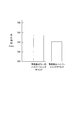
- FIG. 3 is a graph showing the results of verification of fatigue suppression by the hypersonic sound method, in which the response times obtained in the dual task test were averaged for a plurality of test subjects.
- the response time of the subject was about 750 msec in the pattern in which the vehicle sound and the dummy hypersonic sound were output from the speaker.
- the response time of the subject was approximately 740 msec. Therefore, it was confirmed that the response time was shortened by about 10 msec by outputting the hypersonic sound.
- the activation of nerve activity in the brain of the occupant exposed to hypersonic sound increases the amount of neurotransmitters consumed by the nerve activity, and after a long time, the nerve activity This may be due in part to the inability of the intracellular supply of transmitter to keep up.
- the inventors of the present invention have found that it is more effective to output the hypersonic sound only when the occupant is tired than to constantly output the hypersonic sound to the occupant. Got. Therefore, as in the occupant support device 1 according to the present embodiment, it is determined whether or not the occupant is easily fatigued based on the vehicle information. That is, control for operating the suppression unit 50 is performed.
- the vehicle information on the vehicle and the surroundings of the vehicle is acquired, and based on the vehicle information, the occupant is in a state of being easily fatigued. It is determined whether or not the occupant is easily fatigued, and when the occupant is determined to be in a state where the occupant is likely to be tired, a fatigue suppression unit which is mounted on the vehicle and suppresses occupant fatigue by activating the brainstem of the occupant of the vehicle is operated.
- the fatigue suppression unit may be operated. Good. If the fatigue-prone state lasts for less than a predetermined time such as momentary, it is considered that there is no shortage of neurotransmitters in the occupant's brain in the first place. Therefore, when the fatigue-prone state continues for a predetermined time, the unnecessary operation of the fatigue suppression unit can be suppressed by operating the fatigue suppression unit. As a result, a decrease in the effect of suppressing fatigue can be prevented.
- the physical load of the occupant is evaluated, and when the physical load is equal to or more than a predetermined load, it is determined that the occupant is in a state of being easily fatigued. It may be something. Focusing on the size of the physical load on the occupant as a condition for operating the fatigue suppressor, by evaluating the physical load, it is possible to accurately determine the timing of operating the fatigue suppressor, Unnecessary operation of the suppression unit can be suppressed. As a result, a decrease in the effect of suppressing fatigue can be prevented.
- the moving speed of the object in front or the side of the vehicle is acquired, It may be evaluated that the higher the moving speed of the object in front of or on the side of the vehicle, the greater the physical load. Since the information input to the occupant's vision increases as the moving speed of the object in front of or on the side of the vehicle increases, and the occupant is likely to be tired, the physical load is evaluated based on the moving speed of the object. Thus, it is possible to accurately determine the timing at which the fatigue suppression unit operates.
- the lane width of the lane in which the vehicle is traveling is evaluated based on the vehicle information, and the smaller the evaluated lane width, the lower the physical load. It may be evaluated as being large. Assess the physical load based on the lane width, as the narrower the lane in which the vehicle is traveling, the more visual information the occupant needs to process per unit time and the more likely it is that the occupant will be tired. Thereby, the timing for operating the fatigue suppression unit can be determined accurately.
- the road on which the vehicle is traveling is specified based on the vehicle position information included in the vehicle information, and the lane corresponding to the road is used as the road information.
- the lane width of the lane in which the vehicle is traveling may be obtained by reading out road information corresponding to the specified road with reference to the storage unit that stores at least the width. Since the lane width is obtained based on the road information, the physical load can be evaluated based on the accurate lane width. And the timing which operates a fatigue suppression part can be determined correctly.
- the distance between the vehicle and the object on the side of the vehicle is detected, and the smaller the detected distance is, the smaller the lane width is evaluated. It may be.
- the occupant perceives the distance to the object on the side of the vehicle, and the smaller the distance, the more occupant becomes nervous.Therefore, the occupant can accurately determine the physical condition of the occupant based on the distance to the object on the side of the vehicle.
- the load can be evaluated, and the timing for operating the fatigue suppression unit can be accurately determined.
- the brightness outside the vehicle may be detected, and the lower the detected brightness, the greater the physical load may be evaluated.
- the amount of information input to the occupant's vision is reduced, so that the occupant driving the vehicle tends to gaze to obtain more visual information, It is thought that it is easy to get tired.
- the slipperiness of the road surface of the lane on which the vehicle is traveling is detected, and the more the road surface is slippery, the greater the physical load is evaluated. It may be.
- the more slippery the road surface the more occupants tend to try to maintain their posture in line with the slip of the vehicle, and to acquire more acceleration, balance, and visual information as perceived by the semicircular canal, etc.
- At least one acceleration in the front-rear direction, the up-down direction, and the left-right direction of the vehicle is detected, and the larger the detected acceleration, the greater the physical load. It may be evaluated.
- a deviation or the like is likely to occur between the acceleration experienced by the semicircular canal and the movement of the vehicle, and the occupant tends to get sick. Therefore, it is considered that the occupant is easily tired.
- the change speed of the turning angle of the wheel provided in the vehicle is detected, and the larger the detected change speed, the greater the physical load is evaluated. It may be. If the change speed of the turning angle of the wheels provided in the vehicle is high, a deviation or the like is likely to occur between the acceleration felt by the semicircular canal and the movement of the vehicle, and the occupant tends to get sick. Therefore, it is considered that the occupant is easily tired.
- the fatigue suppression unit includes a first sound wave output unit that outputs a first sound wave having a frequency higher than a human audible sound range to the occupant,
- the first sound wave may be output to the occupant by the fatigue suppressing unit to activate the brainstem of the occupant.
- the fatigue suppression unit further includes a second sound wave output unit that outputs a second sound wave having a lower frequency than the first sound wave to the occupant.
- the first sound wave and the second sound wave may be simultaneously output to the occupant by the fatigue suppressing unit to activate the brainstem of the occupant.
- the sound environment can be brought into a state closer to a natural environment sound. As a result, it is possible to reduce the stress of the occupant, and it is possible to increase the effect of suppressing fatigue.
- the functions shown in the above-described embodiment can be implemented by one or a plurality of processing circuits.
- the processing circuit includes a programmed processing device such as a processing device including an electric circuit.
- Processors also include devices such as application specific integrated circuits (ASICs) or conventional circuit components arranged to perform the functions described in the embodiments.
- ASICs application specific integrated circuits
Landscapes
- Physics & Mathematics (AREA)
- General Physics & Mathematics (AREA)
- Traffic Control Systems (AREA)
Abstract
L'invention concerne un procédé d'atténuation de la fatigue et un dispositif d'assistance à un passager, consistant : à déterminer si le passager d'un véhicule se trouve dans un état enclin à la fatigue sur la base d'informations de véhicule du véhicule et de la situation à proximité du véhicule ; et si tel est le cas, à activer une unité d'atténuation de la fatigue afin d'atténuer la fatigue du passager par stimulation des troncs cérébraux du passager.
Priority Applications (2)
| Application Number | Priority Date | Filing Date | Title |
|---|---|---|---|
| PCT/JP2018/025313 WO2020008547A1 (fr) | 2018-07-04 | 2018-07-04 | Procédé d'atténuation de la fatigue et dispositif d'assistance à un passager |
| JP2020528588A JP7067619B2 (ja) | 2018-07-04 | 2018-07-04 | 疲労抑制方法及び乗員支援装置 |
Applications Claiming Priority (1)
| Application Number | Priority Date | Filing Date | Title |
|---|---|---|---|
| PCT/JP2018/025313 WO2020008547A1 (fr) | 2018-07-04 | 2018-07-04 | Procédé d'atténuation de la fatigue et dispositif d'assistance à un passager |
Publications (1)
| Publication Number | Publication Date |
|---|---|
| WO2020008547A1 true WO2020008547A1 (fr) | 2020-01-09 |
Family
ID=69060957
Family Applications (1)
| Application Number | Title | Priority Date | Filing Date |
|---|---|---|---|
| PCT/JP2018/025313 Ceased WO2020008547A1 (fr) | 2018-07-04 | 2018-07-04 | Procédé d'atténuation de la fatigue et dispositif d'assistance à un passager |
Country Status (2)
| Country | Link |
|---|---|
| JP (1) | JP7067619B2 (fr) |
| WO (1) | WO2020008547A1 (fr) |
Cited By (1)
| Publication number | Priority date | Publication date | Assignee | Title |
|---|---|---|---|---|
| CN116030596A (zh) * | 2022-12-30 | 2023-04-28 | 湖北大学 | 一种摩托车疲劳驾驶预警装置及预警方法 |
Citations (11)
| Publication number | Priority date | Publication date | Assignee | Title |
|---|---|---|---|---|
| JPH08203000A (ja) * | 1995-01-27 | 1996-08-09 | Fuji Heavy Ind Ltd | 車両の警報装置 |
| JP2001165686A (ja) * | 2000-10-05 | 2001-06-22 | Mitsubishi Electric Corp | 車載用ナビゲーション装置及び車載用ナビゲーション装置用経路探索装置 |
| JP2008126818A (ja) * | 2006-11-20 | 2008-06-05 | Denso Corp | 自動車用ユーザーもてなしシステム |
| JP2009134525A (ja) * | 2007-11-30 | 2009-06-18 | Equos Research Co Ltd | 車両環境情報通知システム及び車両環境情報通知方法 |
| JP2009146185A (ja) * | 2007-12-14 | 2009-07-02 | Fujitsu Ten Ltd | 疲労度判定装置 |
| JP2011235847A (ja) * | 2010-05-13 | 2011-11-24 | Clarion Co Ltd | ナビゲーション装置 |
| JP2012113477A (ja) * | 2010-11-24 | 2012-06-14 | Denso Corp | 運転疲労度判定装置 |
| JP2013009961A (ja) * | 2009-02-03 | 2013-01-17 | Action Research:Kk | 振動体、乗り物、放送受信装置、通信受信装置、信号再生装置、放送送信装置、及び振動発生空間装置 |
| JP2013061763A (ja) * | 2011-09-13 | 2013-04-04 | Clarion Co Ltd | 判定装置 |
| JP2013152679A (ja) * | 2012-01-26 | 2013-08-08 | Denso Corp | 運転支援装置 |
| WO2016024316A1 (fr) * | 2014-08-11 | 2016-02-18 | 日産自動車株式会社 | Dispositif et procédé de commande de déplacement pour un véhicule |
-
2018
- 2018-07-04 JP JP2020528588A patent/JP7067619B2/ja not_active Expired - Fee Related
- 2018-07-04 WO PCT/JP2018/025313 patent/WO2020008547A1/fr not_active Ceased
Patent Citations (11)
| Publication number | Priority date | Publication date | Assignee | Title |
|---|---|---|---|---|
| JPH08203000A (ja) * | 1995-01-27 | 1996-08-09 | Fuji Heavy Ind Ltd | 車両の警報装置 |
| JP2001165686A (ja) * | 2000-10-05 | 2001-06-22 | Mitsubishi Electric Corp | 車載用ナビゲーション装置及び車載用ナビゲーション装置用経路探索装置 |
| JP2008126818A (ja) * | 2006-11-20 | 2008-06-05 | Denso Corp | 自動車用ユーザーもてなしシステム |
| JP2009134525A (ja) * | 2007-11-30 | 2009-06-18 | Equos Research Co Ltd | 車両環境情報通知システム及び車両環境情報通知方法 |
| JP2009146185A (ja) * | 2007-12-14 | 2009-07-02 | Fujitsu Ten Ltd | 疲労度判定装置 |
| JP2013009961A (ja) * | 2009-02-03 | 2013-01-17 | Action Research:Kk | 振動体、乗り物、放送受信装置、通信受信装置、信号再生装置、放送送信装置、及び振動発生空間装置 |
| JP2011235847A (ja) * | 2010-05-13 | 2011-11-24 | Clarion Co Ltd | ナビゲーション装置 |
| JP2012113477A (ja) * | 2010-11-24 | 2012-06-14 | Denso Corp | 運転疲労度判定装置 |
| JP2013061763A (ja) * | 2011-09-13 | 2013-04-04 | Clarion Co Ltd | 判定装置 |
| JP2013152679A (ja) * | 2012-01-26 | 2013-08-08 | Denso Corp | 運転支援装置 |
| WO2016024316A1 (fr) * | 2014-08-11 | 2016-02-18 | 日産自動車株式会社 | Dispositif et procédé de commande de déplacement pour un véhicule |
Cited By (1)
| Publication number | Priority date | Publication date | Assignee | Title |
|---|---|---|---|---|
| CN116030596A (zh) * | 2022-12-30 | 2023-04-28 | 湖北大学 | 一种摩托车疲劳驾驶预警装置及预警方法 |
Also Published As
| Publication number | Publication date |
|---|---|
| JPWO2020008547A1 (ja) | 2021-12-16 |
| JP7067619B2 (ja) | 2022-05-16 |
Similar Documents
| Publication | Publication Date | Title |
|---|---|---|
| US11377094B2 (en) | System and method for responding to driver behavior | |
| JP6191633B2 (ja) | 運転支援装置 | |
| JP5228970B2 (ja) | 居眠り防止装置 | |
| CN103476622B (zh) | 用于监测车辆的驾驶员的警觉性且刺激其脑电波的方法和装置 | |
| JP6776681B2 (ja) | ドライバ状態判定装置、及びドライバ状態判定プログラム | |
| JP2009261516A (ja) | 覚醒度推定装置 | |
| US20230278565A1 (en) | Driving assistance device | |
| AU2012218054A1 (en) | System and method for responding to driver behavior | |
| WO2018207905A1 (fr) | Système de commande de conduite de véhicule et procédé de commande de conduite de véhicule | |
| JP6701951B2 (ja) | 運転支援装置 | |
| JP2021524787A (ja) | 人間の脳の知覚負荷及び刺激知覚のレベルを決定するシステム及び方法 | |
| WO2014001928A2 (fr) | Système et procédé permettant d'améliorer la vigilance | |
| JP4710502B2 (ja) | 車両用居眠り防止装置及び居眠り防止方法 | |
| JP6455569B2 (ja) | 運転支援方法及び運転支援装置 | |
| WO2020008547A1 (fr) | Procédé d'atténuation de la fatigue et dispositif d'assistance à un passager | |
| JP6648788B1 (ja) | 運転制御調整装置および運転制御調整方法 | |
| KR20130075798A (ko) | 졸음운전감지 시스템 및 그 제어방법 | |
| JP6673070B2 (ja) | ドライバ状態誘導装置、及びドライバ状態誘導プログラム | |
| JP2018032339A (ja) | 運転者体調検知装置及び方法 | |
| JP4882420B2 (ja) | 覚醒度推定装置及び方法 | |
| US10363870B2 (en) | Passenger wake-up apparatus | |
| JP7794078B2 (ja) | 心理状態誘導装置及び心理状態誘導方法 | |
| CN110949309A (zh) | 一种具有疲劳驾驶提示功能的安全带 | |
| JP2009003539A (ja) | 視認力向上支援装置 | |
| JP2013165773A (ja) | 睡眠制御装置 |
Legal Events
| Date | Code | Title | Description |
|---|---|---|---|
| 121 | Ep: the epo has been informed by wipo that ep was designated in this application |
Ref document number: 18925612 Country of ref document: EP Kind code of ref document: A1 |
|
| ENP | Entry into the national phase |
Ref document number: 2020528588 Country of ref document: JP Kind code of ref document: A |
|
| NENP | Non-entry into the national phase |
Ref country code: DE |
|
| 122 | Ep: pct application non-entry in european phase |
Ref document number: 18925612 Country of ref document: EP Kind code of ref document: A1 |