WO2020008627A1 - Dispositif de filtrage, dispositif capteur, procédé de filtrage et programme - Google Patents
Dispositif de filtrage, dispositif capteur, procédé de filtrage et programme Download PDFInfo
- Publication number
- WO2020008627A1 WO2020008627A1 PCT/JP2018/025718 JP2018025718W WO2020008627A1 WO 2020008627 A1 WO2020008627 A1 WO 2020008627A1 JP 2018025718 W JP2018025718 W JP 2018025718W WO 2020008627 A1 WO2020008627 A1 WO 2020008627A1
- Authority
- WO
- WIPO (PCT)
- Prior art keywords
- value
- filtering
- output value
- input value
- filtering device
- Prior art date
- Legal status (The legal status is an assumption and is not a legal conclusion. Google has not performed a legal analysis and makes no representation as to the accuracy of the status listed.)
- Ceased
Links
Images








Classifications
-
- G—PHYSICS
- G01—MEASURING; TESTING
- G01B—MEASURING LENGTH, THICKNESS OR SIMILAR LINEAR DIMENSIONS; MEASURING ANGLES; MEASURING AREAS; MEASURING IRREGULARITIES OF SURFACES OR CONTOURS
- G01B11/00—Measuring arrangements characterised by the use of optical techniques
- G01B11/02—Measuring arrangements characterised by the use of optical techniques for measuring length, width or thickness
- G01B11/026—Measuring arrangements characterised by the use of optical techniques for measuring length, width or thickness by measuring distance between sensor and object
-
- G—PHYSICS
- G01—MEASURING; TESTING
- G01B—MEASURING LENGTH, THICKNESS OR SIMILAR LINEAR DIMENSIONS; MEASURING ANGLES; MEASURING AREAS; MEASURING IRREGULARITIES OF SURFACES OR CONTOURS
- G01B21/00—Measuring arrangements or details thereof, where the measuring technique is not covered by the other groups of this subclass, unspecified or not relevant
- G01B21/02—Measuring arrangements or details thereof, where the measuring technique is not covered by the other groups of this subclass, unspecified or not relevant for measuring length, width, or thickness
- G01B21/04—Measuring arrangements or details thereof, where the measuring technique is not covered by the other groups of this subclass, unspecified or not relevant for measuring length, width, or thickness by measuring coordinates of points
- G01B21/045—Correction of measurements
-
- H—ELECTRICITY
- H03—ELECTRONIC CIRCUITRY
- H03H—IMPEDANCE NETWORKS, e.g. RESONANT CIRCUITS; RESONATORS
- H03H17/00—Networks using digital techniques
- H03H17/02—Frequency selective networks
- H03H17/0248—Filters characterised by a particular frequency response or filtering method
- H03H17/026—Averaging filters
Definitions
- the present invention relates to a filtering device, a sensor device, a filtering method, and a program.
- averaging the measured values includes various arithmetic operations represented by a weighted average in addition to a simple arithmetic average.
- the noise reduction rate can be increased by increasing the number n of data to be subjected to the moving average.
- the number of data n increases, when the measured value includes a change different from noise, the moving average value follows the change with a large delay. Therefore, a technique has been proposed in which the number of data used for the moving average is set according to the accuracy and response time set by the user (for example, see Patent Document 1).
- Patent Literature 1 calculates the moving average once the number of data is set without changing this setting for measurement data that is repeatedly input. For this reason, if the user makes a setting that places importance on accuracy, the delay increases. On the other hand, if the user makes a setting that places importance on the response time, the accuracy decreases. Therefore, there is room for improving responsiveness while securing a certain level of filtering performance for reducing noise.
- the present invention has been made in view of the above circumstances, and has as its object to improve responsiveness while securing a certain level of filtering performance for reducing noise.
- a filtering device of the present invention includes: an obtaining unit that obtains an input value that is repeatedly input; and a filtering unit that obtains an output value by performing filtering that reduces noise included in the input value.
- the means When the difference between the current input value and the past output value exceeds a first threshold value, the means newly weights the current input value with a weight larger than the weight for obtaining the past output value. Output value.
- the filtering unit may use the current input value with a weight larger than the weight for obtaining the past output value. To obtain a new output value.
- FIG. 1 is a block diagram illustrating a configuration of a sensor device according to Embodiment 1 of the present invention. Diagram showing an outline of a moving average according to the first embodiment
- FIG. 7 is a diagram showing a specific example of a moving average according to the first embodiment.
- FIG. 2 is a diagram illustrating a hardware configuration of a filtering device according to the first embodiment. Flowchart showing filtering processing according to Embodiment 1.
- FIG. 9 is a diagram for describing a change in the number of data according to the first embodiment.
- FIG. 9 is a diagram for describing filtering according to the first embodiment.
- FIG. 14 is a diagram for describing filtering according to a modification of the first embodiment.
- FIG. 10 is a diagram showing a comparative example with respect to the modification of the first embodiment. 9 is a flowchart illustrating a filtering process according to a modification of the first embodiment.
- FIG. 1 is a first diagram illustrating an IIR filter according to a second embodiment. Second diagram for explaining an IIR filter according to Embodiment 2.
- FIG. 10 is a diagram for describing filtering according to the second embodiment. Flowchart showing filtering processing according to Embodiment 3.
- FIG. 10 is a diagram for describing filtering according to the third embodiment.
- Embodiment 1 FIG.
- the sensor device 10 is a laser displacement sensor that measures an amount of change in a distance to an object using laser light. As shown in FIG. 1, the sensor device 10 irradiates a laser beam toward the work 30, a lens 12 for forming an image of light reflected on the work 30, and a light transmitted through the lens 12.
- the system control unit 16 controls a laser displacement sensor system including the unit 14, the element control unit 15, and the filtering device 20, and the filtering device 20 reduces noise included in a measurement value output from the measurement unit 14.
- Light emitting element 11 includes a laser diode as a laser element.
- the light receiving element 13 is an image sensor including a plurality of photoelectric conversion elements arranged. Each of the plurality of photoelectric conversion elements outputs a voltage value according to the received light intensity.
- the light receiving element 13 outputs information indicating the distribution of the received light intensity to the measuring unit 14.
- the measuring unit 14 detects a peak from the distribution of the received light intensity, and calculates the amount of displacement from the work 30 by triangulation from the light receiving position of the peak.
- the measurement unit 14 outputs the calculated displacement amount to the filtering device 20 as a measurement value.
- the measuring unit 14 functions as a measuring unit in the claims.
- the element control unit 15 controls light emission of the light emitting element 11 and light reception of the light receiving element 13. Specifically, the element control unit 15 controls the intensity and time of light emission by the light emitting element 11 and controls the timing of imaging by the light receiving element 13.
- the system control unit 16 controls the element control unit 15 to repeatedly execute the light emission of the light emitting element 11 and the light reception of the light receiving element 13, and causes the measuring unit 14 to repeatedly calculate the measured value.
- the system control unit 16 controls the filtering device 20 to set, for example, parameters related to filtering and settings related to an output destination of a filtering result.
- the filtering device 20 is a device that performs filtering on the measured value to reduce the noise included in the measured value and calculates an output value having a relatively high followability to the measured value.
- the filtering device 20 adaptively changes coefficients constituting the filter to reduce a delay when the output value follows the change when the measured value includes a change different from noise.
- the filtering device 20 includes an acquisition unit 21 that acquires a measurement value, a filtering unit 22 that performs filtering on the measurement value, and an output unit 23 that outputs a result of the filtering.
- the acquisition unit 21 acquires a measurement value repeatedly output from the measurement unit 14 as an input value input to the filtering device 20.
- the sampling cycle of the measurement value is, for example, 100 ⁇ s, 1 ms, or 10 ms.
- the acquiring unit 21 outputs the input value to the filtering unit 22 every time the acquiring unit 21 acquires the input value.
- the acquiring unit 21 functions as a claim acquiring unit.
- the filtering unit 22 calculates a noise-reduced output value by a moving average from a plurality of input values acquired during a certain period in the past. Specifically, the filtering unit 22 calculates, as an output value, an average value of n input values including the latest input value at the current time.
- the filtering unit 22 functions as a filtering unit in the claims.
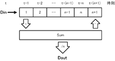
- FIG. 2 shows an outline of the calculation by the filtering unit 22.
- “Din” indicates an input value
- “Dout” indicates an output value.
- the input value Din is added to the first register in the list numbered from “1” to “n + 1”.
- This list corresponds to a first-in first-out queue, and the input value Din obtained immediately before the latest input value Din moves to the second register, and the input values Din are stored in the third and subsequent registers in the newest order. Will be done. Therefore, at time t, the first register stores the input value Din obtained at time t ⁇ 1, and the nth register stores the input value Din obtained at time t ⁇ n. .
- the time here corresponds to the sampling order. In an initial state before an input value is obtained, zero is stored in each register. n is the number of data of the input value to be subjected to the moving average.
- the subscript i in the above equation (1) indicates the number of the acquired input value, and the larger the value of i, the newer the input value of Dini.
- Din i means a current input value
- Din i-1 means an input value obtained immediately before Din i
- Dout i means a current output value
- Dout i-1 means an output value calculated immediately before Dout i .
- the above equation (1) can be modified as the following equation (2).
- the “Sum” register in FIG. 2 holds the sum of the values stored in the first to n-th registers. In this register, zero is initially stored.
- the filtering unit 22 adds the acquired input value Din to the first register, adds this value added to the first register to the value of the “Sum” register, The value of the sum is updated by subtracting the value moved from the n-th register to the (n + 1) -th register from the value of the “Sum” register. Then, the filtering unit 22 obtains the output value Dout by dividing the value of the “Sum” register by n.
- FIG. 3 shows an example of the calculation by the filtering unit 22.
- the value “8” is stored in the first register, and the value “1” is stored in the n-th register.
- the “Sum” register stores the sum “52” of the values stored in the first to n-th registers.
- this input value is added to the first register as shown in the lower part of FIG. From (n + 1) th to (n + 1) th.
- a value “60” is calculated. If the number of data n is 10, “6. An output value of “0” is calculated.
- the output unit 23 outputs the output value output from the filtering unit 22 according to the control of the system control unit 16.
- the output destination is, for example, a display terminal (not shown), a storage device, a signal processing circuit that performs signal processing on an output value of the filtering device 20, or a PLC (Programmable @ Logic) connected to the sensor device 10 via a sensor network. Controller) and other control devices.
- the filtering device 20 includes a processor 41, a main storage unit 42, an auxiliary storage unit 43, an input unit 44, an output unit 45, and a communication unit 46.
- the main storage unit 42, the auxiliary storage unit 43, the input unit 44, the output unit 45, and the communication unit 46 are all connected to the processor 41 via the internal bus 47.
- the processor 41 includes an MPU (Micro Processing Unit), a CPU (Central Processing Unit), or an FPGA (Field Programmable Gate Array).
- the processor 41 realizes various functions of the filtering device 20 by executing the program P1 stored in the auxiliary storage unit 43, and executes processing described below.
- the main storage unit 42 includes a RAM (Random Access Memory).
- the main storage unit 42 is loaded with the program P1 from the auxiliary storage unit 43.
- the main storage unit 42 is used as a work area of the processor 41.
- the auxiliary storage unit 43 includes a nonvolatile memory represented by an electrically erasable programmable read-only memory (EEPROM) and a hard disk drive (HDD).
- EEPROM electrically erasable programmable read-only memory
- HDD hard disk drive
- the auxiliary storage unit 43 stores various data used for the processing of the processor 41, in addition to the program P1.
- the auxiliary storage unit 43 supplies data used by the processor 41 to the processor 41 in accordance with an instruction from the processor 41, and stores the data supplied from the processor 41.
- the input unit 44 includes a terminal for inputting information from outside the filtering device 20.
- the input unit 44 acquires information input from the outside, and notifies the processor 41 of the acquired information.
- the output unit 45 includes a terminal for outputting information to the outside of the filtering device 20.
- the output unit 45 outputs information provided from the processor 41 to the outside according to an instruction from the processor 41.
- the communication unit 46 includes a network interface circuit for communicating with an external device.
- the communication unit 46 receives a signal from the outside and outputs data indicated by the signal to the processor 41.
- the communication unit 46 transmits a signal indicating data output from the processor 41 to an external device.
- FIG. 1 The various functions shown in FIG. 1 are realized by cooperation of the hardware configuration shown in FIG. Specifically, the input unit 44 mainly implements the acquisition unit 21. Mainly, the processor 41 and the main storage unit 42 implement the filtering unit 22. The output unit 45 mainly implements the output unit 23. However, the communication unit 46 may implement the output unit 23 when notifying the external device of the result of the filtering by communication.
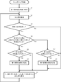
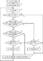
- the filtering process illustrated in FIG. 5 starts when the power of the filtering device 20 is turned on.
- the filtering device 20 sets the first coefficient (1 / n) to an initial value as an initialization process (Step S1). Specifically, the filtering unit 22 substitutes 1 as an initial value for a first coefficient which is the reciprocal of the number n of data to be subjected to the moving average. Thereby, the initial value of the data number n is set to 1.
- the first coefficient (1 / n) means a weight coefficient by which the current input value is multiplied.
- each of the plurality of input values is divided by the number of data n, and this division is equivalent to multiplying each of the plurality of input values by a coefficient (1 / n).
- the coefficient (1 / n) corresponds to the weight of each input value, and is a value in the range from zero to one.
- the filtering device 20 acquires an input value (step S2). Specifically, the acquisition unit 21 acquires the measurement value output from the measurement unit 14. Step S2 corresponds to a claim obtaining step.
- the filtering device 20 determines whether there is a past output value (step S3). Specifically, the filtering unit 22 determines whether or not there is an output value calculated earlier than the output value calculated from the input value acquired in step S2.
- the past output value usually means the previous output value.
- Step S3 If it is determined that there is no past output value (Step S3; No), the processing by the filtering device 20 proceeds to Step S9. On the other hand, when it is determined that there is a past output value (Step S3; Yes), the filtering device 20 determines whether or not the magnitude of the difference between the current input value and the past output value exceeds a threshold (Step S3). Step S4). Specifically, the filtering unit 22 calculates the absolute value of the difference between the current input value acquired in step S2 and the past output value determined to be present in step S3, and this absolute value is It is determined whether or not a predetermined threshold is exceeded.
- the threshold value may be a value stored in advance by the filtering device 20 or a value changed by the user.
- the filtering device 20 determines whether the first coefficient is larger than the lower limit (Step S5). Specifically, the filtering unit 22 determines whether the current first coefficient (1 / n) is greater than a predetermined lower limit.
- the lower limit value may be a value stored in advance by the filtering device 20 or a value changed by the user. This lower limit value corresponds to the reciprocal of the maximum value of the number of data to be subjected to the moving average. This lower limit is, for example, 1/64, 1/16384, or 1/131072.
- the determination in step S5 is normally affirmed.
- Step S5 If it is determined that the first coefficient is not larger than the lower limit (Step S5; No), the filtering device 20 proceeds to Step S9 without changing the first coefficient.
- the filtering device 20 decreases the first coefficient (Step S6). Specifically, the filtering unit 22 changes n of the first coefficient (1 / n) to a number larger by one. In other words, the filtering unit 22 increases the number n of data to be subjected to the moving average by one. Immediately after the activation of the filtering device 20, the number n of data is changed from 1 to 2, and the first coefficient is reduced from 1 to 1 /. Thereafter, the processing by the filtering device 20 proceeds to step S9.
- step S7 determines whether the first coefficient is smaller than the upper limit. Specifically, the filtering unit 22 determines whether the current first coefficient (1 / n) is smaller than a predetermined upper limit.
- the upper limit value may be a value stored in advance by the filtering device 20 or a value changed by a user. This upper limit corresponds to the reciprocal of the minimum value of the number n of data to be subjected to the moving average.
- the upper limit value is 1, but is not limited thereto, and may be, for example, 1/8 or 1/64.
- step S7 If it is determined that the first coefficient is not smaller than the upper limit (step S7; No), the filtering device 20 proceeds to step S9 without changing the first coefficient.
- the filtering device 20 increases the first coefficient (Step S8). Specifically, the filtering unit 22 changes the first coefficient (1 / n) to 1 by setting the number of data n to 1. As a result, the number n of data to be subjected to the moving average becomes only one for the input value to be acquired next.
- the filtering device 20 calculates an output value from a value obtained by multiplying the input value obtained in step S2 by the first coefficient (1 / n) (step S9). Specifically, the filtering unit 22 multiplies the current input value by a first coefficient (1 / n) and the second coefficient (1 / n) for each of the past (n-1) input values. ) Is calculated as the sum of the value obtained by multiplying the output value and the output value.
- the second coefficient has a value equal to the first coefficient.
- the second coefficient means a weight coefficient by which a past input value is multiplied.
- Step S9 corresponds to a filtering step in the claims.
- the filtering device 20 has not yet acquired the past input values immediately after the activation, but since the number of data n was set to 1 in step S1, the input values acquired in step S2 are used as output values as they are. I do.
- step S2 the filtering device 20 repeats the processing from step S2.
- an output value with reduced noise is calculated while changing the first coefficient with respect to the input value repeatedly acquired.
- FIG. 6 schematically shows a change in the number n of data to be subjected to the moving average.
- the upper part of FIG. 6 shows a case where the data number n is equal to 10.
- the number n of data is changed to 11, and the calculation is executed as shown in the middle part of FIG.
- the subtraction from the register value of “Sum” is omitted, and only the addition of a new input value is executed.
- the number n of data is decreased and the first coefficient is increased, the number n of data is changed to 1 and the operation is performed as shown in the lower part of FIG. However, immediately after the data number n is reduced, the new input value is stored in the “Sum” register as it is.
- the filtering device 20 when the difference between the current input value and the past output value exceeds the threshold value, the filtering device 20 outputs the current input value with a weight larger than the weight for obtaining the past output value. To obtain a new output value.
- the filtering device 20 calculates an output value from a value obtained by multiplying a current input value by a first coefficient (1 / n).
- the first coefficient corresponds to the degree of emphasis on the current input value. The larger the first coefficient is, the smaller the contribution of other data is, and the shorter the delay is, while the smaller the first coefficient is, the more the other data is. This will further reduce noise.
- the filtering device 20 increases the first coefficient to reduce the delay, and when the difference is small, reduces the first coefficient. To reduce noise. Thereby, the performance of filtering for reducing noise can be improved in accordance with the situation. As a result, it contributes to the improvement of the productivity of the production equipment using the filtering device 20 and the improvement of the quality of products.
- FIG. 7 schematically shows the transition of the input value and the output value, the magnitude of the difference between the input value and the previous output value, and the first coefficient.
- a broken line L11 in the upper part of FIG. 7 indicates a transition of a value separated by a threshold from the previous output value, and if the input value is out of the range surrounded by the two broken lines L11, the determination in step S4 in FIG. Will be affirmed.
- the magnitude of the difference between the previous output value and the input value is equal to or smaller than the threshold value, and the first coefficient has converged to the lower limit value.
- the number of data n is changed to 1 and the first coefficient increases to 1, and the newly calculated output value becomes the input value. Be equal.
- the number of data n increases to 2 and the first coefficient decreases to ⁇ , and a plurality of input values are again subjected to the moving average.
- the output value can follow this change with a small delay.
- the filtering device 20 calculates the output value by the moving average, and increases or decreases the number of data of the past input value to be the moving average according to the magnitude of the difference between the past output value and the current input value. I let it. Since the moving average is relatively easy to implement and is an effective method for reducing noise, the filtering device 20 can easily improve the performance of reducing noise.
- the filtering device 20 sets the initial value of the first coefficient (1 / n) to 1.
- the input value of the number n of data to be subjected to the moving average has not yet been input immediately after the start of the filtering, so that the output value does not become an appropriate value, and special processing immediately after the start is performed. Required.
- the initial value of the number of data n is set to 1 and the output value becomes equal to the input value, so that an appropriate output value can be easily obtained.
- the first coefficient (1 / n) is a value in the range from zero to 1, and the filtering device 20 determines that the difference between the past output value and the current input value exceeds the threshold value. , The first coefficient was set to 1. Accordingly, when the difference between the past output value and the current input value increases, the newly calculated output value becomes equal to the input value, and the output value can follow the input value with a small delay.
- the filtering process performed by the filtering device 20 is not limited to the above-described process.
- step S6 in FIG. 5 it has been described that the number n of data is increased by 1 to decrease the first coefficient.
- the decrease width of the first coefficient is not limited to this, and the number n of data is set to 2
- the first coefficient may be decreased by increasing by a factor of two. If the number of data n is doubled, the number of data n becomes a power of 2 and the calculation becomes easy.
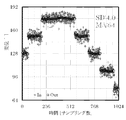
- FIG. 8 shows a simulation result of an input value and an output value when the inventors increase the number of data n twice. In this simulation, a value in which noise is superimposed on the amount of displacement that changes stepwise is used as the input value. “In” in FIG. 8 indicates an input value, and “Out” indicates an output value. As shown in FIG. 8, the output value changes in a step-like manner, and it can be seen that the noise is reduced by the filtering process, and the output value follows a change different from the noise included in the input value with a small delay. .
- FIG. 9 shows the result of the moving average when the number of data n is fixed to 64 without changing the first coefficient under the same conditions as in the simulation of FIG.
- the output value reduces the noise to about 1/8, but it can be seen that a delay corresponding to 64 samplings has occurred with respect to the input value.
- step S3 the filtering device 10 determines whether or not the magnitude of the difference between the output value and the input value continuously exceeds the first threshold (step S11). Specifically, the filtering unit 22 determines whether the magnitude of the difference continuously exceeds the first threshold for a predetermined number of times or more. At this time, the value of the output exceeding the threshold value may be stored, and thereafter, the determination may be sequentially performed based on the difference between the input and the stored output.
- the output value when the difference from the input value exceeds the first threshold value is stored as a reference value, and for the next and subsequent input values, the error between the input value and the reference value is a predetermined error. May be determined continuously.
- the predetermined number of times is, for example, three, ten, or 100 times, and may be the number of times that the filtering device 20 stores in advance, or may be changed by the user.
- the first threshold value is a threshold value for determining whether to increase the first coefficient, and may be a value stored in advance by the filtering device 20 or may be changed by the user.
- Step S11 If it is determined that the magnitude of the difference continuously exceeds the first threshold (Step S11; Yes), the filtering device 20 proceeds to Step S7. On the other hand, when it is determined that the magnitude of the difference does not continuously exceed the first threshold (Step S11; No), the filtering device 20 determines that the magnitude of the difference between the output value and the input value is It is determined whether the value is below two thresholds (step S12). Specifically, the filtering unit 22 determines whether or not the magnitude of the difference is continuously lower than the second threshold for a predetermined number of times or more. This number may be the same as or different from the number used for the determination in step S11.
- the number of times is, for example, 3, 10, or 100 times, and may be the number of times that the filtering device 20 stores in advance, or may be changed by the user.
- the second threshold is different from the first threshold, and is a threshold for determining whether to decrease the first coefficient.
- the second threshold value may be a value stored in the filtering device 20 in advance, or may be changed by the user. Normally, a value larger than the first threshold is set as the second threshold.
- Step S12 If it is determined that the magnitude of the difference is continuously below the second threshold (Step S12; Yes), the filtering device 20 proceeds to Step S5. On the other hand, when it is determined that the magnitude of the difference does not continuously fall below the second threshold (step S12; No), the processing by the filtering device 20 proceeds to step S9. As a result, an output value with reduced noise is calculated while changing the first coefficient with respect to the input value repeatedly acquired.
- the first threshold for decreasing the first coefficient and the second threshold for increasing the first coefficient are set as different values. If the magnitude of the difference between the output value and the input value is larger than the first threshold and smaller than the second threshold, the first coefficient is not changed. For this reason, if the magnitude of the difference between the output value and the input value is stable within a certain range, the first coefficient is fixed, and high-speed arithmetic processing can be easily realized.
- the example shown in FIG. 5 can be said to be the case where the first threshold value and the second threshold value are equal.
- the first coefficient is changed when the magnitude of the difference between the output value and the input value continuously exceeds the first threshold value and when the magnitude of the difference continuously falls below the second threshold value. This prevents the first coefficient from being changed each time the input value greatly fluctuates due to temporary noise. As a result, arithmetic processing can be executed stably.
- each of the first coefficient and the one or more second coefficients is preferably a positive value, and is preferably in a range from zero to one. Further, the sum of the first coefficient and one or more second coefficients is desirably 1. Each of the plurality of second coefficients may have a different value.
- Embodiment 2 FIG. Next, the second embodiment will be described focusing on differences from the first embodiment.
- the filtering based on the moving average is applied to the input value.
- an IIR filter may be applied.
- an example in which an IIR filter is applied to an input value will be described.
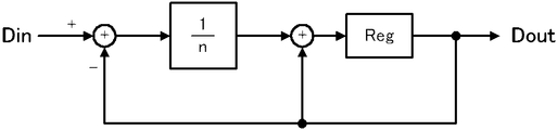
- FIG. 11 shows an outline of the calculation by the filtering unit 22 according to the present embodiment.
- “Reg” in the block diagram of FIG. 11 indicates an operation of registering in a register.
- a value obtained by multiplying a current input value Din i by a first coefficient (1 / n) and a value obtained by multiplying a past output value Dout i-1 by a third coefficient ((n-1) / n) Is output as a new output value Dout i .
- This calculation is represented by the following equation (3).
- the third coefficient is a weight coefficient for multiplying a past output value.
- the current output value is calculated by inner product of the previous output value and the current input value.
- a new output value is calculated as a weighted average of the current input value and the past output value.
- the output value corresponds to a weighted average of past input values.
- the current input value is multiplied by the first coefficient (1 / n). Therefore, by increasing the first coefficient (1 / n), it is possible to obtain an output value that follows the current input value by reducing the delay, and to decrease the first coefficient (1 / n). Noise can be further reduced by a weighted average of past input values.
- the operation by the filtering unit 22 may be realized by a block diagram as shown in FIG.
- the calculation of the output value shown in the example of FIG. 12 is represented by the following expression (4) obtained by modifying the above expression (3).
- the filtering device 20 calculates the current output value as a weighted average of the current input value and the past output value. Thereby, the filtering device 20 can perform the same processing as in FIG. 5 and achieve the same effect as in the first embodiment.
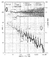
- FIG. 13 shows the result of comparison between the IIR filter and the moving average when the number of data n is doubled by the inventors.
- a point P21 indicated by “+” indicates an input value
- a diamond-shaped point P22 indicates a standard deviation of the input value
- a large circle-shaped point P23 indicates an output value by the moving average
- a round point P24 indicates an output value by the IIR filter.
- the line L21 indicates the theoretical noise reduction rate 1 / ⁇ n
- the large diamond-shaped point P25 indicates the noise reduction rate by the moving average
- the small diamond-shaped point P26 indicates the noise reduction rate by the IIR filter.
- the IIR filter can reduce the noise substantially along the theoretical reduction rate.
- the moving average and the noise reduction rate by the IIR filter are calculated as (standard deviation of output value) / (standard deviation of input value).
- the operation can be performed only by preparing one register.
- the filtering process can be executed with less hardware resources than the moving average that requires a plurality of registers as shown in FIG.
- a new output value may be calculated using a plurality of past output values.
- the first coefficient by which the current input value is multiplied is (1 / n) and the third coefficient by which the past output value is multiplied is ((n-1) / n).
- Each of the third coefficients may have a value different from that described above. However, it is desirable that each of the first coefficient and the one or more third coefficients be a positive value and be within a range from zero to one. Further, the sum of the first coefficient and one or more third coefficients is desirably 1. Each of the plurality of third coefficients may have a different value.
- Embodiment 3 FIG. Next, a third embodiment will be described focusing on differences from the first embodiment.
- the threshold is a parameter that is defined in advance. However, it is desirable that the threshold be determined according to the magnitude of noise. Therefore, an example in which a threshold is determined according to the magnitude of noise will be described below.
- the filtering device 20 executes the filtering process shown in FIG.
- the filtering device 20 sets a threshold based on the standard deviation of past input values (step S31).
- the filtering unit 22 calculates the standard deviation of P input values defined in advance, and sets a value of Q times the calculated standard deviation as a threshold.
- the values of P and Q may be values stored in the filtering device 20 in advance, or may be changed by the user.
- P is desirably a large number of times to obtain a valid standard deviation, for example, 32, 64, or 128.
- Q is determined according to the magnitude of the noise and the displacement amount of the measurement target. For example, if the amount of displacement changes stepwise and the amount of change is significantly larger than the noise, an output value that follows the displacement with a small delay while reducing noise by setting P to a relatively large value. Can be obtained.
- P may be, for example, 3 or 4.
- the filtering device 20 calculates the threshold from the standard deviation of the input value, and changes the first coefficient based on the threshold. As a result, even in the case where the magnitude of the noise fluctuates over time, the first coefficient can be changed using an appropriate threshold value according to the magnitude of the noise to perform appropriate filtering.
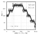
- FIG. 15 shows a simulation of the input value, the output value, and the standard deviation in the case where the inventors have specified the threshold according to the standard deviation of the past input values.
- “SD” in FIG. 15 indicates a standard deviation.
- a value obtained by superimposing noise on the amount of displacement that changes stepwise was used as an input value.
- the output value can follow the displacement amount that changes stepwise with a small delay. Further, the output value changes in a step-like manner, and noise can be reduced.
- the first threshold and the second threshold in the modification of FIG. 10 may be defined according to the standard deviation.
- the threshold value can be defined according to the standard deviation.
- the threshold value may be defined according to the statistical value of at least one of the past input value and output value, without being limited to the standard deviation.
- a statistic one or more of a variation in a difference between an output value and an input value, a peak value or a peak position in a histogram of the difference, a deviation of the difference, and a time variation of a statistic related to the histogram are described. It is conceivable to define the threshold value according to.
- the senor device 10 is a laser displacement device.
- the present invention is not limited to this, and the sensor device 10 may be another sensing device.
- the input unit 44 and the output unit 45 may form a user interface that exchanges information with a user.
- the change amount when changing the first coefficient is not limited to the above example, and may be arbitrarily set by the user.
- the initial value of the first coefficient is not limited to the above example, and may be arbitrarily set by the user.
- the present invention is not limited to this.
- the sensor device 10 and the filtering device 20 may be configured as different devices. It is also conceivable that the sensor device 10 and the filtering device 20 are integrally configured.
- the processor 41 may realize the measuring unit 14, and the acquiring unit 21 and the measuring unit 14 may be integrally formed.
- the filtering device 20 may calculate an output value according to the following equation (5).
- the number K of past input values used for calculation and the number M of past output values used for calculation may be set arbitrarily.
- the filtering device 20 when the filtering device 20 changes the first coefficient according to the current input value, the filtering device 20 calculates a new output value from the current input value using the changed first coefficient, but is not limited thereto.
- the first coefficient whose value has been changed may be applied to input values for the next and subsequent times.
- the function of the filtering device 20 can be realized by dedicated hardware or a normal computer system.
- the program P1 executed by the processor 41 is stored in a non-transitory computer-readable recording medium and distributed, and the program P1 is installed in a computer to configure an apparatus that executes the above-described processing. be able to.
- a recording medium include a flexible disk, a CD-ROM (Compact Disc-Only Memory), a DVD (Digital Versatile Disc), and an MO (Magneto-Optical Disc).
- the program P1 may be stored in a disk device of a server device on a communication network represented by the Internet, and may be superimposed on a carrier wave and downloaded to a computer, for example.
- the above-described processing can also be achieved by starting and executing the program P1 while transferring the program P1 via the communication network.
- the above-described processing can also be achieved by causing all or a part of the program P1 to be executed on a server device and executing the program while the computer transmits and receives information regarding the processing via a communication network.
- the means for realizing the function of the filtering device 20 is not limited to software, and a part or all of the means may be realized by dedicated hardware including a circuit.
- the present invention is suitable for filtering for reducing noise.
Landscapes
- Physics & Mathematics (AREA)
- General Physics & Mathematics (AREA)
- Image Processing (AREA)
- Length Measuring Devices By Optical Means (AREA)
- Length Measuring Devices With Unspecified Measuring Means (AREA)
- Indication And Recording Devices For Special Purposes And Tariff Metering Devices (AREA)
- Measurement And Recording Of Electrical Phenomena And Electrical Characteristics Of The Living Body (AREA)
Abstract
Ce dispositif de filtrage (20) comprend une unité d'acquisition (21) et une unité de filtrage (22). L'unité d'acquisition (21) acquiert une valeur d'entrée introduite de façon répétée. L'unité de filtrage (22) obtient une valeur de sortie par filtrage, ce qui réduit le bruit contenu dans la valeur d'entrée. En outre, lorsque la différence entre une valeur d'entrée courante et une valeur de sortie précédente dépasse une première valeur de seuil, l'unité de filtrage (22) obtient une nouvelle valeur de sortie par pondération de la valeur d'entrée courante avec un poids qui est supérieur à un poids pour obtenir ladite valeur de sortie précédente.
Priority Applications (4)
| Application Number | Priority Date | Filing Date | Title |
|---|---|---|---|
| CN201880095293.2A CN112384752A (zh) | 2018-07-06 | 2018-07-06 | 滤波装置、传感器装置、滤波方法及程序 |
| JP2019511514A JP6524371B1 (ja) | 2018-07-06 | 2018-07-06 | フィルタリング装置、センサ装置、フィルタリング方法及びプログラム |
| US17/252,281 US11365962B2 (en) | 2018-07-06 | 2018-07-06 | Filtering device, sensor device, filtering method and program |
| PCT/JP2018/025718 WO2020008627A1 (fr) | 2018-07-06 | 2018-07-06 | Dispositif de filtrage, dispositif capteur, procédé de filtrage et programme |
Applications Claiming Priority (1)
| Application Number | Priority Date | Filing Date | Title |
|---|---|---|---|
| PCT/JP2018/025718 WO2020008627A1 (fr) | 2018-07-06 | 2018-07-06 | Dispositif de filtrage, dispositif capteur, procédé de filtrage et programme |
Publications (1)
| Publication Number | Publication Date |
|---|---|
| WO2020008627A1 true WO2020008627A1 (fr) | 2020-01-09 |
Family
ID=66730593
Family Applications (1)
| Application Number | Title | Priority Date | Filing Date |
|---|---|---|---|
| PCT/JP2018/025718 Ceased WO2020008627A1 (fr) | 2018-07-06 | 2018-07-06 | Dispositif de filtrage, dispositif capteur, procédé de filtrage et programme |
Country Status (4)
| Country | Link |
|---|---|
| US (1) | US11365962B2 (fr) |
| JP (1) | JP6524371B1 (fr) |
| CN (1) | CN112384752A (fr) |
| WO (1) | WO2020008627A1 (fr) |
Cited By (1)
| Publication number | Priority date | Publication date | Assignee | Title |
|---|---|---|---|---|
| JPWO2021149240A1 (fr) * | 2020-01-24 | 2021-07-29 |
Families Citing this family (1)
| Publication number | Priority date | Publication date | Assignee | Title |
|---|---|---|---|---|
| US11092470B2 (en) * | 2019-09-13 | 2021-08-17 | Micro Motion Inc. | Magnetic flowmeter with noise adaptive dead time |
Citations (6)
| Publication number | Priority date | Publication date | Assignee | Title |
|---|---|---|---|---|
| JP2012018199A (ja) * | 2010-07-06 | 2012-01-26 | Konica Minolta Business Technologies Inc | 画像形成装置 |
| JP2012031776A (ja) * | 2010-07-30 | 2012-02-16 | Toyota Motor Corp | 内燃機関の燃料噴射量制御装置 |
| JP2013088290A (ja) * | 2011-10-18 | 2013-05-13 | Nanao Corp | 動体判別装置、センサのゆらぎ検出装置、表示装置、動体判別方法及びセンサのゆらぎ検出方法 |
| JP2015503157A (ja) * | 2011-11-28 | 2015-01-29 | ネオノード インコーポレイテッド | 交替反射レンズファセットを有する光学要素 |
| JP2016116221A (ja) * | 2014-12-10 | 2016-06-23 | 三星電子株式会社Samsung Electronics Co.,Ltd. | 3d表示のための装置及び方法 |
| JP2017044626A (ja) * | 2015-08-28 | 2017-03-02 | 三陽工業株式会社 | レール計測装置、レール計測方法、およびプログラム |
Family Cites Families (17)
| Publication number | Priority date | Publication date | Assignee | Title |
|---|---|---|---|---|
| DE2210881C2 (de) * | 1972-03-07 | 1973-12-06 | Metabowerke Kg, Closs, Rauch & Schnizler, 7440 Nuertingen | Verzahnungsmeßgerat |
| JP3789728B2 (ja) * | 1999-08-10 | 2006-06-28 | ジーイー横河メディカルシステム株式会社 | プロジェクションデータ補正方法および装置並びに放射線断層撮像装置 |
| JP4270733B2 (ja) * | 2000-09-14 | 2009-06-03 | 株式会社東芝 | 画像のサイズ変換方法及び装置 |
| US7711044B1 (en) * | 2001-10-29 | 2010-05-04 | Trident Microsystems (Far East) Ltd. | Noise reduction systems and methods |
| US9052777B2 (en) | 2001-11-02 | 2015-06-09 | Neonode Inc. | Optical elements with alternating reflective lens facets |
| JP4430466B2 (ja) | 2004-06-22 | 2010-03-10 | 株式会社キーエンス | 光学式変位計 |
| DE102004036069B4 (de) | 2004-07-24 | 2017-04-06 | Dr. Johannes Heidenhain Gmbh | Verfahren und Vorrichtung zum Bilden von rauschgefilterten Ausgangswerten aus rauschbehafteten Eingangswerten |
| JP4745032B2 (ja) | 2005-11-18 | 2011-08-10 | シャープ株式会社 | フィルタ装置 |
| JP4914188B2 (ja) * | 2006-11-27 | 2012-04-11 | 富士重工業株式会社 | 平滑化フィルタ装置および速度検出装置 |
| CN101888355A (zh) * | 2010-04-22 | 2010-11-17 | 深圳市云海通讯股份有限公司 | 一种自适应滤波器及滤波方法 |
| JP5218494B2 (ja) | 2010-07-30 | 2013-06-26 | オムロン株式会社 | 変位センサ |
| JP5925390B1 (ja) * | 2014-12-02 | 2016-05-25 | 三菱電機株式会社 | 変位センサ、変位検出装置及び変位検出方法 |
| JP2016183882A (ja) | 2015-03-25 | 2016-10-20 | 住友電気工業株式会社 | Ofケーブルの評価方法およびofケーブルの評価装置 |
| WO2016165116A1 (fr) * | 2015-04-16 | 2016-10-20 | 中国科学院自动化研究所 | Système de débruitage de vidéo basé sur une corrélation de bruit |
| US10270973B2 (en) * | 2015-12-08 | 2019-04-23 | Canon Kabushiki Kaisha | Control device and imaging apparatus with a subject selectable mode with higher image blur correction |
| DE102016224636B3 (de) | 2016-12-09 | 2018-01-25 | Robert Bosch Gmbh | Verfahren zur Adaption einer elektronischen Filtereinheit, eine elektronische Filtereinheit sowie eine Vorrichtung mit einer solchen Filtereinheit |
| WO2019051841A1 (fr) * | 2017-09-18 | 2019-03-21 | 深圳市汇顶科技股份有限公司 | Procédé de détermination de coefficient de filtre et dispositif associé, et terminal |
-
2018
- 2018-07-06 WO PCT/JP2018/025718 patent/WO2020008627A1/fr not_active Ceased
- 2018-07-06 US US17/252,281 patent/US11365962B2/en active Active
- 2018-07-06 JP JP2019511514A patent/JP6524371B1/ja not_active Expired - Fee Related
- 2018-07-06 CN CN201880095293.2A patent/CN112384752A/zh active Pending
Patent Citations (6)
| Publication number | Priority date | Publication date | Assignee | Title |
|---|---|---|---|---|
| JP2012018199A (ja) * | 2010-07-06 | 2012-01-26 | Konica Minolta Business Technologies Inc | 画像形成装置 |
| JP2012031776A (ja) * | 2010-07-30 | 2012-02-16 | Toyota Motor Corp | 内燃機関の燃料噴射量制御装置 |
| JP2013088290A (ja) * | 2011-10-18 | 2013-05-13 | Nanao Corp | 動体判別装置、センサのゆらぎ検出装置、表示装置、動体判別方法及びセンサのゆらぎ検出方法 |
| JP2015503157A (ja) * | 2011-11-28 | 2015-01-29 | ネオノード インコーポレイテッド | 交替反射レンズファセットを有する光学要素 |
| JP2016116221A (ja) * | 2014-12-10 | 2016-06-23 | 三星電子株式会社Samsung Electronics Co.,Ltd. | 3d表示のための装置及び方法 |
| JP2017044626A (ja) * | 2015-08-28 | 2017-03-02 | 三陽工業株式会社 | レール計測装置、レール計測方法、およびプログラム |
Cited By (2)
| Publication number | Priority date | Publication date | Assignee | Title |
|---|---|---|---|---|
| JPWO2021149240A1 (fr) * | 2020-01-24 | 2021-07-29 | ||
| WO2021149240A1 (fr) * | 2020-01-24 | 2021-07-29 | 理化工業株式会社 | Dispositif de calcul, indicateur, régulateur de température et procédé associé |
Also Published As
| Publication number | Publication date |
|---|---|
| US20210148693A1 (en) | 2021-05-20 |
| US11365962B2 (en) | 2022-06-21 |
| JP6524371B1 (ja) | 2019-06-05 |
| JPWO2020008627A1 (ja) | 2020-07-09 |
| CN112384752A (zh) | 2021-02-19 |
Similar Documents
| Publication | Publication Date | Title |
|---|---|---|
| TWI440269B (zh) | 先進的雷射波長控制技術 | |
| JP2021002819A (ja) | フィルタリング装置、センサ装置、フィルタリング方法、およびフィルタリングプログラム | |
| JP6486888B2 (ja) | 移動平均フィルタの動作制御方法 | |
| US10564658B2 (en) | Servo control apparatus, servo control method and computer-readable recording medium | |
| WO2016045095A1 (fr) | Procédé, appareil et dispositif de correction de distance de détection | |
| WO2021042382A1 (fr) | Procédé et appareil de télémétrie par radar laser, dispositif informatique et support de mémoire | |
| JP5958392B2 (ja) | 時系列計測信号のノイズ低減装置 | |
| WO2020008627A1 (fr) | Dispositif de filtrage, dispositif capteur, procédé de filtrage et programme | |
| JP2016161343A (ja) | 自動調整機能を有するエンコーダの信号処理装置 | |
| CN106681536B (zh) | 非暂时性电脑可读取媒体及影像感测装置 | |
| JP2016208556A (ja) | デマンド予測装置及びデマンド予測方法 | |
| JP2011226924A (ja) | 追尾装置 | |
| RU2622852C1 (ru) | Адаптивное цифровое сглаживающее и прогнозирующее устройство | |
| JP6598029B2 (ja) | アクティブ消音装置 | |
| JP6388754B1 (ja) | 信号処理装置、センサ装置および信号処理方法 | |
| JP6000652B2 (ja) | パルスモータ制御装置およびパルス信号生成方法 | |
| CN114722343A (zh) | 一种离合器位置信号滤波方法、装置、存储介质及终端 | |
| CN116952273A (zh) | 一种时间标定方法、电子设备及计算机可读存储介质 | |
| JP2010181200A (ja) | レーダ信号処理装置 | |
| WO2020121722A1 (fr) | Dispositif, procédé, et programme d'estimation | |
| JP2017033464A (ja) | 状態推定装置 | |
| KR102900246B1 (ko) | 적응 필터 설정 방법 및 이를 위한 전자 장치 | |
| JP7258247B2 (ja) | レーダ信号処理装置、レーダ装置、及びレーダ信号処理方法 | |
| TWI557729B (zh) | 語音信號處理裝置及語音信號處理方法 | |
| JP7814627B1 (ja) | 信号処理装置、信号処理方法およびプログラム |
Legal Events
| Date | Code | Title | Description |
|---|---|---|---|
| ENP | Entry into the national phase |
Ref document number: 2019511514 Country of ref document: JP Kind code of ref document: A |
|
| 121 | Ep: the epo has been informed by wipo that ep was designated in this application |
Ref document number: 18925545 Country of ref document: EP Kind code of ref document: A1 |
|
| NENP | Non-entry into the national phase |
Ref country code: DE |
|
| 122 | Ep: pct application non-entry in european phase |
Ref document number: 18925545 Country of ref document: EP Kind code of ref document: A1 |