WO2020008665A1 - 半導体リレーモジュールおよび半導体リレー回路 - Google Patents
半導体リレーモジュールおよび半導体リレー回路 Download PDFInfo
- Publication number
- WO2020008665A1 WO2020008665A1 PCT/JP2019/001663 JP2019001663W WO2020008665A1 WO 2020008665 A1 WO2020008665 A1 WO 2020008665A1 JP 2019001663 W JP2019001663 W JP 2019001663W WO 2020008665 A1 WO2020008665 A1 WO 2020008665A1
- Authority
- WO
- WIPO (PCT)
- Prior art keywords
- output
- terminal
- circuit
- input
- semiconductor relay
- Prior art date
- Legal status (The legal status is an assumption and is not a legal conclusion. Google has not performed a legal analysis and makes no representation as to the accuracy of the status listed.)
- Ceased
Links
Images




Classifications
-
- H—ELECTRICITY
- H03—ELECTRONIC CIRCUITRY
- H03K—PULSE TECHNIQUE
- H03K17/00—Electronic switching or gating, i.e. not by contact-making and –breaking
- H03K17/51—Electronic switching or gating, i.e. not by contact-making and –breaking characterised by the components used
- H03K17/78—Electronic switching or gating, i.e. not by contact-making and –breaking characterised by the components used using opto-electronic devices, i.e. light-emitting and photoelectric devices electrically- or optically-coupled
- H03K17/785—Electronic switching or gating, i.e. not by contact-making and –breaking characterised by the components used using opto-electronic devices, i.e. light-emitting and photoelectric devices electrically- or optically-coupled controlling field-effect transistor switches
-
- H—ELECTRICITY
- H03—ELECTRONIC CIRCUITRY
- H03K—PULSE TECHNIQUE
- H03K17/00—Electronic switching or gating, i.e. not by contact-making and –breaking
- H03K17/51—Electronic switching or gating, i.e. not by contact-making and –breaking characterised by the components used
- H03K17/56—Electronic switching or gating, i.e. not by contact-making and –breaking characterised by the components used by the use, as active elements, of semiconductor devices
- H03K17/687—Electronic switching or gating, i.e. not by contact-making and –breaking characterised by the components used by the use, as active elements, of semiconductor devices the devices being field-effect transistors
- H03K17/6871—Electronic switching or gating, i.e. not by contact-making and –breaking characterised by the components used by the use, as active elements, of semiconductor devices the devices being field-effect transistors the output circuit comprising more than one controlled field-effect transistor
-
- H—ELECTRICITY
- H03—ELECTRONIC CIRCUITRY
- H03K—PULSE TECHNIQUE
- H03K17/00—Electronic switching or gating, i.e. not by contact-making and –breaking
- H03K17/51—Electronic switching or gating, i.e. not by contact-making and –breaking characterised by the components used
- H03K17/56—Electronic switching or gating, i.e. not by contact-making and –breaking characterised by the components used by the use, as active elements, of semiconductor devices
- H03K17/687—Electronic switching or gating, i.e. not by contact-making and –breaking characterised by the components used by the use, as active elements, of semiconductor devices the devices being field-effect transistors
- H03K17/6871—Electronic switching or gating, i.e. not by contact-making and –breaking characterised by the components used by the use, as active elements, of semiconductor devices the devices being field-effect transistors the output circuit comprising more than one controlled field-effect transistor
- H03K17/6874—Electronic switching or gating, i.e. not by contact-making and –breaking characterised by the components used by the use, as active elements, of semiconductor devices the devices being field-effect transistors the output circuit comprising more than one controlled field-effect transistor in a symmetrical configuration
Definitions
- the present disclosure relates to a semiconductor relay module and a semiconductor relay circuit.
- Patent Document 1 discloses a semiconductor relay including two output semiconductor relays and one grounding semiconductor relay.
- the two output semiconductor relays are connected in series with each other.
- the grounding semiconductor relay is provided between a connection point of the two output semiconductor relays and a grounding point.
- each of the output semiconductor relay and the grounding semiconductor relay has two MOSFETs connected in anti-series.
- a photodiode array is connected to the MOSFET.
- the semiconductor relay is provided with a first input circuit and a second input circuit.
- the first input circuit has a first LED.
- the photodiode arrays of the two output semiconductor relays are configured to generate an electromotive force by the emission of the first LED to turn on the MOSFET of each output semiconductor relay.
- the second input circuit has a second LED.
- the photodiode array of the grounding semiconductor relay is configured to generate an electromotive force by the emission of the second LED to turn on the MOSFET of the grounding semiconductor relay.
- the on / off of the two output semiconductor relays is controlled by the common first input circuit.
- the first and second input circuits are respectively connected to two input terminals. For this reason, connection and the like may be complicated, and it may be difficult to design a circuit board.
- a semiconductor relay module includes a first semiconductor relay, a second semiconductor relay, a third semiconductor relay, a package, a first input terminal, a second input terminal, and a third input terminal. , A first output terminal, a second output terminal, a third output terminal, and a first connection line.
- the first semiconductor relay includes a first input circuit and a first output circuit.
- the second semiconductor relay includes a second input circuit and a second output circuit.
- the third semiconductor relay includes a third input circuit and a third output circuit.
- the package houses the first semiconductor relay, the second semiconductor relay, and the third semiconductor relay inside.
- the first input terminal, the second input terminal, and the third input terminal are provided on the package, and are arranged so that a part thereof is exposed to the outside of the package.
- the first output terminal, the second output terminal, and the third output terminal are provided on the package, and are arranged so that a part thereof is exposed to the outside of the package.
- the first connection line connects the first output circuit and the second output circuit within the package.
- the first input circuit is connected to the first input terminal and the second input terminal in the package.
- the second input circuit is connected to the first input terminal and the second input terminal in the package.
- the third input circuit is connected to the first or second input terminal and the third input terminal in the package.
- the first output circuit is connected to the first output terminal and the first connection line in the package.
- the second output circuit is connected to the second output terminal and the first connection line in the package.
- the third output circuit is connected to the third output terminal and the first connection line in the package.
- the first output circuit and the second output circuit are turned on, and the third output circuit is turned off.
- the first output terminal and the second output terminal become conductive, and the first connection line and the third output terminal become non-conductive.
- the first output circuit and the second output circuit are turned off, and the third output circuit is turned off. Is turned on, the first output terminal and the second output terminal become non-conductive, and the first connection line and the third output terminal become conductive.
- an input circuit is provided for each of the first semiconductor relay, the second semiconductor relay, and the third semiconductor relay. Therefore, stable operation characteristics can be secured. Further, the input circuit of each semiconductor relay is connected to an input terminal inside the package. Therefore, a semiconductor relay module that can easily design a circuit board can be realized.
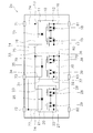
- FIG. 1 is a configuration diagram illustrating an example of the semiconductor relay circuit 1a according to the first embodiment of the present disclosure.
- the semiconductor relay circuit 1a includes a semiconductor relay module 2a, a power supply terminal 3, a control terminal 4, and a control circuit 5.
- the semiconductor relay module 2a includes a first semiconductor relay 10, a second semiconductor relay 20, a third semiconductor relay 30, a package 70, a first input terminal 71, a second input terminal 72, and a third input terminal 73.
- the package 70 houses the first semiconductor relay 10, the second semiconductor relay 20, and the third semiconductor relay 30 therein.
- the package 70 is formed of, for example, an insulating resin. However, the package 70 is not limited to resin, and may be made of another material such as ceramic.
- the package 70 has, for example, a rectangular shape in plan view. However, the package 70 is not limited to a rectangular shape, and may have another shape.
- the first input terminal 71, the second input terminal 72, and the third input terminal 73 are provided on the package 70. Each of the first input terminal 71, the second input terminal 72, and the third input terminal 73 is arranged so that a part thereof is exposed to the outside of the package 70.
- the semiconductor relay module 2a further includes a first output terminal 81, a second output terminal 82, and a third output terminal 83. The first output terminal 81, the second output terminal 82, and the third output terminal 83 are provided on the package 70. Each of the first output terminal 81, the second output terminal 82, and the third output terminal 83 is arranged such that a part thereof is exposed to the outside of the package 70.
- the first semiconductor relay 10, the second semiconductor relay 20, and the third semiconductor relay 30 are arranged in the package 70 in the longitudinal direction of the package 70.
- the third semiconductor relay 30 is disposed between the first semiconductor relay 10 and the second semiconductor relay 20 in the longitudinal direction of the package 70.
- the first semiconductor relay 10 includes a first input circuit 11 and a first output circuit 12.
- the first output circuit 12 When a current is flowing through the first input circuit 11, the first output circuit 12 is turned on. When no current is flowing through the first input circuit 11, the first output circuit 12 is turned off.
- the second semiconductor relay 20 includes a second input circuit 21 and a second output circuit 22. When a current is flowing through the second input circuit 21, the second output circuit 22 is turned on. When no current is flowing through the second input circuit 21, the second output circuit 22 is turned off.
- the third semiconductor relay 30 includes a third input circuit 31 and a third output circuit 32. When a current is flowing through the third input circuit 31, the third output circuit 32 is turned on. When no current flows through the third input circuit 31, the third output circuit 32 is turned off.
- the on state means a state in which current flows in the output circuit.
- the off state means a state in which no current flows in the output circuit.
- the first input circuit 11 is connected to the first input terminal 71 and the second input terminal 72 in the package 70.
- the second input circuit 21 is connected to the first input terminal 71 and the second input terminal 72 in the package 70.
- the third input circuit 31 is connected to a first input terminal 71 and a third input terminal 73 in the package 70.
- the first input circuit 11 is connected to the first input terminal 71 via the connection line 74.
- the first input circuit 11 is connected to a second input terminal 72 via a connection line 75.
- the second input circuit 21 is connected to the first input terminal 71 via a connection line 76.
- the second input circuit 21 is connected to the second input terminal 72 via a connection line 77.
- the third input circuit 31 is connected to the first input terminal 71 via a connection line 78.
- the third input circuit 31 is connected to the third input terminal 73 via a connection line 79.
- the connection lines 74-79 are arranged in the package 70.
- the first output circuit 12 is connected to the first output terminal 81 and the first connection line 80 in the package 70.
- the second output circuit 22 is connected to the second output terminal 82 and the first connection line 80 in the package 70.
- the first output circuit 12 and the second output circuit 22 are connected in series within the package 70 via a first connection line 80.
- the third output circuit 32 is connected to the third output terminal 83 and the first connection line 80 in the package 70.
- the first connection line 80 is arranged in the package 70.
- FIG. 2 is a configuration diagram showing an example of the semiconductor relay module 2a.
- the first input circuit 11 of the first semiconductor relay 10 includes a first input unit 13, a second input unit 14, and a light emitting element 15.
- the first input unit 13 is connected to a first input terminal 71.
- the second input unit 14 is connected to the second input terminal 72.
- the light emitting element 15 is connected to the first input unit 13 and the second input unit 14. The light emitting element 15 emits light when a current flows through the first input circuit 11.
- the second input circuit 21 of the second semiconductor relay 20 includes a first input unit 23, a second input unit 24, and a light emitting element 25.
- the first input unit 23 is connected to the first input terminal 71.
- the second input unit 24 is connected to the second input terminal 72.
- the light emitting element 25 is connected to the first input unit 23 and the second input unit 24. The light emitting element 25 emits light when a current flows through the first input circuit 21.
- the third input circuit 31 of the third semiconductor relay 30 includes a first input unit 33, a second input unit 34, and a light emitting element 35.
- the first input unit 33 is connected to the first input terminal 71.
- the second input unit 34 is connected to the third input terminal 73.
- the light emitting element 35 is connected to the first input unit 33 and the second input unit 34. The light emitting element 35 emits light when a current flows through the first input circuit 31.
- the first output circuit 12 of the first semiconductor relay 10 includes a first output unit 16, a second output unit 17, and two MOSFETs 18 and 19.
- the first output unit 16 is connected to a first output terminal 81.
- the second output unit 17 is connected to the first connection line 80.
- the MOSFETs 18 and 19 are connected in series so that the directions of the parasitic diodes are opposite to each other.
- the MOSFETs 18 and 19 are switched between an on state and an off state depending on whether or not the light emitting element 25 emits light. With the MOSFETs 18 and 19 turned on, the first output section 16 and the second output section 17 conduct. When the MOSFETs 18 and 19 are off, the first output unit 16 and the second output unit 17 are non-conductive.
- the second output circuit 22 of the second semiconductor relay 20 includes a first output unit 26, a second output unit 27, and two MOSFETs 28 and 29.
- the first output unit 26 is connected to the first connection line 80.
- the second output unit 27 is connected to the second output terminal 82.
- the MOSFETs 28 and 29 are connected in series so that the directions of the parasitic diodes are opposite to each other.
- the MOSFETs 28 and 29 are switched between an on state and an off state according to whether or not the light emitting element 25 emits light. With the MOSFETs 28 and 29 turned on, the first output section 26 and the second output section 27 conduct. When the MOSFETs 28 and 29 are off, the first output section 26 and the second output section 27 are non-conductive.
- the third output circuit 32 of the third semiconductor relay 30 includes a first output unit 36, a second output unit 37, and two MOSFETs 38 and 39.
- the first output unit 36 is connected to the first connection line 80.
- the second output unit 37 is connected to the third output terminal 83.
- the MOSFETs 38 and 39 are connected in series so that the directions of the parasitic diodes are opposite to each other.
- the MOSFETs 38 and 39 are switched between an on state and an off state depending on whether the light emitting element 25 emits light. With the MOSFETs 38 and 39 turned on, the first output section 36 and the second output section 37 conduct. When the MOSFETs 38 and 39 are off, the first output unit 36 and the second output unit 37 are non-conductive.
- the first input terminal 71, the second input terminal 72, and the third input terminal 73 are connected to the power supply terminal 3 and the control terminal 4 via the control circuit 5.
- the power supply terminal 3 is supplied with a power supply voltage.
- An input signal is supplied to the control terminal 4.
- the control circuit 5 includes a first circuit 91, a second circuit 92, and a third circuit 93.
- the first circuit 91 connects the power terminal 3 and the first input terminal 71.
- the second circuit 92 connects the control terminal 4 and the second input terminal 72 via the transistor 94 and the resistor 95.
- the third circuit 93 connects the control terminal 4 and the third input terminal 73 via the transistors 96 and 97 and the resistor 98.
- the transistor 96 is connected to the power supply terminal 3 via the resistor 99. Note that the configuration of the control circuit 5 is not limited to that shown in FIG. 1 and may be changed.
- the first output terminal 81 is connected to the first external output terminal 6.
- the second output terminal 82 is connected to the second external output terminal 7.
- the third output terminal 83 is connected to the ground point GND. That is, the third output terminal 83 is a ground terminal for grounding the first connection line 80.
- the control circuit 5 switches the energization state of each input terminal of the semiconductor relay module 2a between the first state and the second state according to the input signal supplied to the control terminal 4.
- the first state is a state in which a current flows through the first input terminal 71 and the second input terminal 72 and no current flows through the third input terminal 73.
- the second state is a state in which current does not flow through the first input terminal 71 and the second input terminal 72, and current flows through the third input terminal 73.
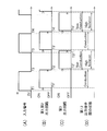
- FIG. 3 is a timing chart showing the operation of the semiconductor relay module 2a according to the voltage control of the input signal.
- FIG. 3A shows a change in the voltage of the input signal supplied to the control terminal 4.
- FIG. 3B shows a change in the ON / OFF state of the first output circuit 12 of the first semiconductor relay 10 and the second output circuit 22 of the second semiconductor relay 20.
- FIG. 3C shows a change in the ON / OFF state of the third output circuit 32 of the third semiconductor relay 30.
- FIG. 3D shows a change in the state of conduction / non-conduction between the first output terminal 81 and the second output terminal 82.
- the control circuit 5 changes the state of energization to each of the input terminals 71 to 73 of the semiconductor relay module 2a to the first state. State. That is, a current flows through the first input terminal 71 and the second input terminal 72, and no current flows through the third input terminal 73. As a result, a current flows through the first input circuit 11 and the second input circuit 21, and as shown in FIG. 3B, the first output circuit 12 and the second output circuit 12 are slightly delayed from the time T1 by a time T1 '. 22 is turned on. Further, since no current flows through the third input circuit 31, the third output circuit 32 is off as shown in FIG. 3C. Thereby, as shown in FIG. 3D, the first output terminal 81 and the second output terminal 82 become conductive at time T1 '. At this time, the first connection line 80 and the third output terminal 83 become non-conductive.
- the control circuit 5 changes the state of energization to each of the input terminals 71 to 73 of the semiconductor relay module 2a to the second. State. That is, no current flows through the first input terminal 71 and the second input terminal 72, and a current flows through the third input terminal 73. As a result, no current flows through the first input circuit 11 and the second input circuit 21, and as shown in FIG. 3B, the first output circuit 12 and the second output circuit 12 are slightly delayed from the time T2 by a time T2 '. 22 is turned off. Further, as shown in FIG.
- the third output circuit 32 is turned on at a time T2 ′′ slightly delayed from the time T2 ′. Thereby, as shown in FIG. 3D, the first output circuit 32 is turned on after the time T2 ′.
- the terminal 81 and the second output terminal 82 become non-conductive, and after the time T2 ′′, the first connection line 80 and the third output terminal 83 become conductive, so that the first connection line 80 becomes the third output terminal. 83 and grounded. Thereby, good isolation characteristics can be obtained.
- the first output circuit 12 is The second output circuit 22 is turned off.
- the third output circuit 32 is turned on at a time T4 ′′ slightly delayed from the time T4 ′.
- the first output terminal 81 and the second output terminal 82 become non-conductive, and after the time T4 ′′, the first connection line 80 and the third output terminal 83 become conductive.
- the first output circuit 12 of the first semiconductor relay 10 and the second output circuit 22 of the second semiconductor relay 20 are connected in series with each other, and The state can be switched between an on state and an off state. Further, when the first output terminal 81 and the second output terminal 82 are non-conductive, the first connection line 80 is connected to the third output terminal 83 to be grounded. Thereby, good isolation characteristics can be obtained between the first output terminal 81 and the second output terminal 82.
- the input circuits 11, 21, 31 of the semiconductor relays 10, 20, 30 are respectively connected to input terminals 71, 72, 73 inside the package 70.
- the output circuits 12, 22, and 32 of the semiconductor relays 10, 20, and 30 are connected to output terminals 81, 82, and 83 inside the package 70, respectively. Therefore, it is possible to avoid a complicated wiring configuration in which the wirings cross each other on the circuit board, and to simplify the wirings.
- the semiconductor relay module 2a that can reduce the transmission loss of the high-frequency signal and can easily design the circuit board can be realized.
- the first semiconductor relay 10 and the second semiconductor relay 20 may be low on-resistance semiconductor relays
- the third semiconductor relay 30 may be a low terminal capacitance type semiconductor relay. That is, the output on-resistance of the first semiconductor relay 10 and the output on-resistance of the second semiconductor relay 20 are each smaller than the output on-resistance of the third semiconductor relay 30, and between the output terminals of the third semiconductor relay 30.
- the capacity may be smaller than the capacity between the output terminals of the first semiconductor relay 10 and the capacity between the output terminals of the second semiconductor relay 20. Thereby, good insertion loss and isolation characteristics can be realized.
- all of the first to third semiconductor relays 10, 20, 30 may be low-terminal-capacity semiconductor relays having a capacitance between output terminals of 12 pF or less.
- the capacitance between the output terminals of the low terminal capacitance type semiconductor relay is more preferably 0.8 pF or less, and further preferably 0.2 pF or less.
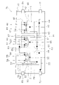
- FIG. 4 is a configuration diagram illustrating an example of the semiconductor relay circuit 1b according to the second embodiment.
- the same components as those in the first embodiment are denoted by the same reference numerals in the configuration of the semiconductor relay circuit 1b according to the second embodiment.
- the semiconductor relay circuit 1b includes a semiconductor relay module 2b.
- the semiconductor relay module 2b includes a fourth semiconductor relay 40, a fifth semiconductor relay 50, a sixth semiconductor relay 60, a fourth output terminal 84, and a fifth output terminal in addition to the configuration of the semiconductor relay module 2a described above. 85 and a second connection line 86.
- the fourth to sixth semiconductor relays 40, 50, 60 are arranged in parallel with the direction in which the first to third semiconductor relays 10, 20, 30 are arranged.
- the fourth to sixth semiconductor relays 40, 50, 60 are arranged in a direction intersecting the first to third semiconductor relays 10, 20, 30 with respect to the first to third semiconductor relays 10, 20, 30. Are located.
- the arrangement of the fourth to sixth semiconductor relays 40, 50, 60 may be changed.
- the first to sixth semiconductor relays 10, 20, 30, 40, 50, 60 may be arranged in a line in the longitudinal direction of the package 70.
- the fourth semiconductor relay 40 includes a fourth input circuit 41 and a fourth output circuit 42. When a current flows through the fourth input circuit 41, the fourth output circuit 42 is turned on. When no current flows through the fourth input circuit 41, the fourth output circuit 42 is turned off.
- the fifth semiconductor relay 50 includes a fifth input circuit 51 and a fifth output circuit 52. When a current is flowing through the fifth input circuit 51, the fifth output circuit 52 is turned on. When no current is flowing through the fifth input circuit 51, the fifth output circuit 52 is turned off.
- the sixth semiconductor relay 60 includes a sixth input circuit 61 and a sixth output circuit 62. When a current flows through the sixth input circuit 61, the sixth output circuit 62 is turned on. When no current flows through the sixth input circuit 61, the sixth output circuit 62 is turned off.
- the fourth output terminal 84 and the fifth output terminal 85 are provided on the package 70 and are arranged so that a part thereof is exposed to the outside of the package 70.
- the second connection line 86 connects the fourth output circuit 42 and the fifth output circuit 52 in the package 70.
- the fourth output terminal 84 is connected to the third external output terminal 8.
- the fifth output terminal 85 is connected to the fourth external output terminal 9.
- the fourth input circuit 41 is connected to the first input terminal 71 and the second input terminal 72 in the package 70.
- the fifth input circuit 51 is connected to the first input terminal 71 and the second input terminal 72 in the package 70.
- the sixth input circuit 61 is connected to the first input terminal 71 and the third input terminal 73 in the package 70.
- the fourth output circuit 42 is connected to the fourth output terminal 84 and the second connection line 86 in the package 70.
- the fifth output circuit 52 is connected to the fifth output terminal 85 and the second connection line 86 in the package 70.
- the sixth output circuit 62 is connected to the third output terminal 83 and the second connection line 86 in the package 70.
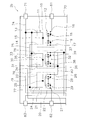
- FIGS. 5 and 6 are diagrams showing an example of the configuration of the semiconductor relay module 2b.
- the fourth input circuit 41 of the fourth semiconductor relay 40 includes a first input unit 43, a second input unit 44, and a light emitting element 45.
- the first input unit 43 is connected to the first input terminal 71.
- the second input unit 44 is connected to the second input terminal 72.
- the fifth input circuit 51 of the fifth semiconductor relay 50 includes a first input unit 53, a second input unit 54, and a light emitting element 55.
- the first input unit 53 is connected to the first input terminal 71.
- the second input unit 54 is connected to the second input terminal 72.
- the sixth input circuit 61 of the sixth semiconductor relay 60 includes a first input unit 63, a second input unit 64, and a light emitting element 65.
- the first input unit 63 is connected to the first input terminal 71.
- the second input section 64 is connected to the third input terminal 73.
- the configuration of the light emitting elements 45, 55, 65 of the fourth to sixth semiconductor relays 40, 50, 60 is the same as the light emitting elements 15, 25, 35 of the first to third semiconductor relays 10, 20, 30 described above. Therefore, detailed description is omitted.
- the fourth output circuit 42 of the fourth semiconductor relay 40 includes a first output unit 46, a second output unit 47, and two MOSFETs 48 and 49.
- the first output unit 46 is connected to the fourth output terminal 84.
- the second output unit 47 is connected to the second connection line 86.
- the fifth output circuit 52 of the fifth semiconductor relay 50 includes a first output unit 56, a second output unit 57, and two MOSFETs 58 and 59.
- the first output section 56 is connected to the second connection line 86.
- the second output unit 57 is connected to the fifth output terminal 85.
- the sixth output circuit 62 of the sixth semiconductor relay 60 includes a first output section 66, a second output section 67, and two MOSFETs 68 and 69.
- the first output section 66 is connected to the second connection line 86.
- the second output section 67 is connected to the third output terminal 83.
- the configuration of the MOSFETs 48, 49, 58, 59, 68, 69 of the fourth to sixth semiconductor relays is similar to the MOSFETs 18, 19, 28, 29, 38, 39 of the first to third semiconductor relays. Detailed description is omitted.
- the semiconductor relay module 2b in the first state in which current flows through the first input terminal 71 and the second input terminal 72 and no current flows through the third input terminal 73, the first output circuit 12 and the second output circuit 22
- the fourth output circuit 42 and the fifth output circuit 52 are turned on, and the third output circuit 32 and the sixth output circuit 62 are turned off.
- the first output terminal 81 and the second output terminal 82 conduct, the fourth output terminal 84 and the fifth output terminal 85 conduct, and the first connection line 80 and the third output terminal 83 do not conduct.
- the second connection line 86 and the third output terminal 83 become non-conductive.
- the semiconductor relay module 2b according to the second embodiment described above is controlled by voltage control of an input signal supplied to the control terminal 4, similarly to the semiconductor relay module 2a according to the first embodiment.
- the fourth output circuit 42 and the fifth output circuit 52 are switched between an on state and an off state, similarly to the first output circuit 12 and the second output circuit 22 shown in FIG. 3B.
- the sixth output circuit 62 is switched between an on state and an off state, similarly to the third output circuit 32 shown in FIG. 3C.
- the fourth output terminal 84 and the fifth output terminal 85 are switched between a conductive state and a non-conductive state, like the first output terminal 81 and the second output terminal 82 shown in FIG. 3D.
- the first output circuit 12 of the first semiconductor relay 10 and the second output circuit 22 of the second semiconductor relay 20 are connected in series with each other, and the fourth output circuit of the fourth semiconductor relay 40 42 and the fifth output circuit 52 of the fifth semiconductor relay 50 are connected in series with each other. Then, these output circuits are simultaneously switched between the ON state and the OFF state.
- the third semiconductor relay 30 controls the connection of the first connection line 80 connecting the first output circuit 12 and the second output circuit 22 to the ground GND.
- the sixth semiconductor relay 60 controls the connection of the second connection line 86 connecting the fourth output circuit 42 and the fifth output circuit 52 to the ground GND.
- the semiconductor relay module 2b according to the second embodiment wiring is performed by avoiding a complicated wiring configuration in which wirings cross each other on a circuit board. Can be simplified. Thus, the semiconductor relay module 2b that can reduce the transmission loss of the high-frequency signal and can easily design the circuit board can be realized.
- the structures of the semiconductor relay circuit, the semiconductor relay module, and the semiconductor relay are not limited to those of the above-described embodiment, and may be changed.
- the number of semiconductor relays included in the semiconductor relay module is not limited to three or six.
- the number of semiconductor relays may be four or more, or seven or more.
- the third input circuit 31 may be connected to the second input terminal 72 and the third input terminal 73 in the package 70.
- the sixth input circuit 61 may be connected to the second input terminal 72 and the third input terminal 73 inside the package 70.
- the arrangement of the first to third semiconductor relays 10, 20, and 30 in the semiconductor relay module 2a according to the first embodiment is not limited to the above-described embodiment, and may be changed.
- a second semiconductor relay 20 may be arranged between the first semiconductor relay 10 and the third semiconductor relay 30.
- the arrangement of the first to sixth semiconductor relays 10, 20, 30, 40, 50, 60 is not limited to that of the above-described embodiment, but may be changed. Is also good.
- the arrangement of the input terminals and / or the output terminals is not limited to the above-described embodiment, and may be changed.
- control circuit 5 changes the energized state of each input terminal of the semiconductor relay module 2a to the first state and the second state by controlling the current of the input signal to the second input terminal 72 and the third input terminal 73. It may be configured to switch to.
- FIG. 8 is a timing chart showing the operation of the semiconductor relay module 2a according to the current control of the input signal.
- FIG. 8A shows a change in the current of the input signal supplied to the second input terminal 72.
- FIG. 8B shows a change in the current of the input signal supplied to the third input terminal 73.
- FIG. 8C shows a change in the ON / OFF state of the first output circuit 12 of the first semiconductor relay 10 and the second output circuit 22 of the second semiconductor relay 20.
- FIG. 8C shows a change in the ON / OFF state of the third output circuit 32 of the third semiconductor relay 30.
- FIG. 8E shows a change in the state of conduction / non-conduction between the first output terminal 81 and the second output terminal 82.
- the semiconductor relay module 2a The energized state to each input terminal is the first state. That is, a current flows through the first input terminal 71 and the second input terminal 72, and no current flows through the third input terminal 73. As a result, a current flows through the first input circuit 11 and the second input circuit 21, and as shown in FIG. 8C, the first output circuit 12 and the second output circuit 12 are slightly delayed from the time T1 by a time T1 '. 22 is turned on. In addition, since no current flows in the third input circuit 31, the third output circuit 32 is turned off as shown in FIG. 8D. Thereby, as shown in FIG. 8E, the first output terminal 81 and the second output terminal 82 conduct at time T1 '. At this time, the first connection line 80 and the third output terminal 83 become non-conductive.
- the input signal to the second input terminal 72 is turned off, and as shown in FIG. 8B, at time T3, an on input signal is supplied to the third input terminal 73.
- the energized state to each input terminal of the semiconductor relay module 2a becomes the second state. That is, no current flows through the first input terminal 71 and the second input terminal 72, and a current flows through the third input terminal 73.
- the third output circuit 32 is turned on at a time T3 'slightly delayed from the time T3.
- the first output terminal 81 and the second output terminal 82 become non-conductive after time T2 '.
- the first connection line 80 and the third output terminal 83 conduct. Therefore, as shown in FIG. 8E, when the first output terminal 81 and the second output terminal 82 are non-conductive, the first connection line 80 is grounded via the third output terminal 83.
- the semiconductor relay module 2b according to the second embodiment may also be controlled in the same manner as described above by controlling the current of the input signal to the second input terminal 72 and the third input terminal 73.
Landscapes
- Electronic Switches (AREA)
Abstract
第1入力回路は、パッケージ内で第1入力端子と第2入力端子とに接続されている。第2入力回路は、パッケージ内で第1入力端子と第2入力端子とに接続されている。第3入力回路は、パッケージ内で第1入力端子又は第2入力端子と、第3入力端子とに接続されている。第1出力回路は、パッケージ内で第1出力端子と第1接続線とに接続されている。第2出力回路は、パッケージ内で第2出力端子と第1接続線とに接続されている。第3出力回路は、パッケージ内で第3出力端子と第1接続線とに接続されている。
Description
本開示は、半導体リレーモジュールおよび半導体リレー回路に関する。
特許文献1には、2つの出力用半導体リレーと1つの接地用半導体リレーとを備えた半導体リレーが開示されている。2つの出力用半導体リレーは、互いに直列に接続されている。接地用半導体リレーは、2つの出力用半導体リレーの接続点と接地点との間に設けられている。
この半導体リレーでは、出力用半導体リレーと接地用半導体リレーとのそれぞれが、逆直列に接続された2つのMOSFETを有している。MOSFETにはフォトダイオードアレイが接続されている。また、半導体リレーには、第1入力回路と第2入力回路とが設けられている。第1入力回路は第1のLEDを有している。2つの出力用半導体リレーのフォトダイオードアレイは、第1のLEDの発光により起電力を発生させて、各出力用半導体リレーのMOSFETをONするように構成されている。第2入力回路は、第2のLEDを有している。接地用半導体リレーのフォトダイオードアレイは、この第2のLEDの発光により起電力を発生させて、接地用半導体リレーのMOSFETをONするように構成されている。
上記の半導体リレーでは、共通の第1入力回路によって、2つの出力用半導体リレーのオン/オフが制御される。しかし、このような構成では、安定した動作特性を確保することは容易ではない。また、第1、第2入力回路はそれぞれ2つの入力端子に接続されている。そのため、結線等が複雑化し、回路基板の設計が困難になる場合がある。
そこで、本開示は、安定した動作特性を確保すると共に、回路基板の設計を容易に行える半導体リレーモジュールを提供することを課題とする。
本開示の一態様に係る半導体リレーモジュールは、第1半導体リレーと、第2半導体リレーと、第3半導体リレーと、パッケージと、第1入力端子と、第2入力端子と、第3入力端子と、第1出力端子と、第2出力端子と、第3出力端子と、第1接続線とを含む。第1半導体リレーは、第1入力回路と第1出力回路とを含む。第2半導体リレーは、第2入力回路と第2出力回路とを含む。第3半導体リレーは、第3入力回路と第3出力回路とを含む。
パッケージは、第1半導体リレーと、第2半導体リレーと、第3半導体リレーとを内部に収容する。第1入力端子と、第2入力端子と、第3入力端子とは、パッケージに設けられ、一部がパッケージの外部に露出するようにそれぞれ配置される。第1出力端子と、第2出力端子と、および第3出力端子とは、パッケージに設けられ、一部がパッケージの外部に露出するようにそれぞれ配置される。第1接続線は、パッケージ内で第1出力回路と第2出力回路とを接続する。
第1入力回路は、パッケージ内で第1入力端子と第2入力端子とに接続される。第2入力回路は、パッケージ内で第1入力端子と第2入力端子とに接続される。第3入力回路は、パッケージ内で第1入力端子又は第2入力端子と、第3入力端子とに接続される。第1出力回路は、パッケージ内で第1出力端子と第1接続線とに接続される。第2出力回路は、パッケージ内で第2出力端子と第1接続線とに接続される。第3出力回路は、パッケージ内で第3出力端子と第1接続線とに接続される。
第1入力端子と第2入力端子とに電流が流れ、第3入力端子に電流が流れない第1状態で、第1出力回路と第2出力回路とがオン状態となり、第3出力回路がオフ状態となることで、第1出力端子と第2出力端子とが導通し、且つ、第1接続線と第3出力端子とが非導通となる。第1入力端子と第2入力端子とに電流が流れず、第3入力端子に電流が流れている第2状態で、第1出力回路と第2出力回路とがオフ状態となり、第3出力回路がオン状態となることで、第1出力端子と第2出力端子とが非導通となり、且つ、第1接続線と第3出力端子とが導通する。
本開示の一態様に係る半導体リレーモジュールによれば、第1半導体リレーと、第2半導体リレーと、第3半導体リレーとのそれぞれに対して入力回路が設けられている。そのため、安定した動作特性を確保することができる。また、パッケージの内部で、各半導体リレーの入力回路が入力端子に接続されている。そのため、回路基板の設計を容易に行える半導体リレーモジュールを実現することができる。
以下、本開示の一例を図面に従って説明する。なお、以下の説明では、必要に応じて特定の方向あるいは位置を示す用語を用いるが、それらの用語の使用は図面を参照した開示の理解を容易にするためであって、それらの用語の意味によって本開示の技術的範囲が限定されるものではない。また、以下の説明は、本質的に例示に過ぎず、本開示、その適用物、あるいは、その用途を制限することを意図するものではない。さらに、図面は模式的なものであり、各寸法の比率等は現実のものとは必ずしも合致していなくてもよい。
図1は、本開示の第1実施形態に係る半導体リレー回路1aの一例を示す構成図である。図1に示すように、半導体リレー回路1aは、半導体リレーモジュール2aと、電源端子3と、制御端子4と、制御回路5とを含む。半導体リレーモジュール2aは、第1半導体リレー10と、第2半導体リレー20と、第3半導体リレー30と、パッケージ70と、第1入力端子71と、第2入力端子72と、第3入力端子73とを含む。
パッケージ70は、第1半導体リレー10と、第2半導体リレー20と、第3半導体リレー30とを内部に収容する。パッケージ70は、例えば絶縁性を有する樹脂で形成されている。ただし、パッケージ70は、樹脂に限らず、セラミック等の他の材料製であってもよい。パッケージ70は、例えば平面視で長方形状を有している。ただし、パッケージ70は、長方形状に限らず、他の形状であってもよい。
第1入力端子71と、第2入力端子72と、第3入力端子73とは、パッケージ70に設けられる。第1入力端子71と、第2入力端子72と、第3入力端子73との各々は、一部がパッケージ70の外部に露出するように配置されている。半導体リレーモジュール2aは、第1出力端子81と、第2出力端子82と、第3出力端子83とをさらに含む。第1出力端子81と、第2出力端子82と、第3出力端子83とは、パッケージ70に設けられている。第1出力端子81と、第2出力端子82と、第3出力端子83との各々は、一部がパッケージ70の外部に露出するように配置されている。
半導体リレーモジュール2aでは、パッケージ70の内部で、第1半導体リレー10と、第2半導体リレー20と、第3半導体リレー30とが、パッケージ70の長手方向に並んで配置されている。第3半導体リレー30は、パッケージ70の長手方向において、第1半導体リレー10と第2半導体リレー20との間に配置されている。
第1半導体リレー10は、第1入力回路11と第1出力回路12とを含む。第1入力回路11に電流が流れているときには、第1出力回路12はオン状態となる。第1入力回路11に電流が流れていないときには、第1出力回路12はオフ状態となる。第2半導体リレー20は、第2入力回路21と第2出力回路22とを含む。第2入力回路21に電流が流れているときには、第2出力回路22はオン状態となる。第2入力回路21に電流が流れていないときには、第2出力回路22はオフ状態となる。第3半導体リレー30は、第3入力回路31と第3出力回路32とを含む。第3入力回路31に電流が流れているときには、第3出力回路32はオン状態となる。第3入力回路31に電流が流れていないときには、第3出力回路32はオフ状態となる。なお、オン状態とは、出力回路において電流が流れる状態を意味する。オフ状態とは、出力回路において電流が流れない状態を意味する。
第1入力回路11は、パッケージ70内で第1入力端子71と第2入力端子72とに接続されている。第2入力回路21は、パッケージ70内で第1入力端子71と第2入力端子72とに接続されている。第3入力回路31は、パッケージ70内で第1入力端子71と、第3入力端子73とに接続されている。
詳細には、第1入力回路11は、接続線74を介して第1入力端子71に接続されている。第1入力回路11は、接続線75を介して第2入力端子72に接続されている。第2入力回路21は、接続線76を介して第1入力端子71に接続されている。第2入力回路21は、接続線77を介して第2入力端子72に接続されている。第3入力回路31は、接続線78を介して第1入力端子71に接続されている。第3入力回路31は、接続線79を介して第3入力端子73に接続されている。接続線74-79は、パッケージ70内に配置されている。
第1出力回路12は、パッケージ70内で第1出力端子81と第1接続線80とに接続されている。第2出力回路22は、パッケージ70内で第2出力端子82と第1接続線80とに接続されている。第1出力回路12と第2出力回路22とは、パッケージ70内で第1接続線80を介して互いに直列に接続されている。第3出力回路32は、パッケージ70内で第3出力端子83と第1接続線80とに接続されている。第1接続線80は、パッケージ70内に配置されている。
図2は、半導体リレーモジュール2aの一例を示す構成図である。図2に示すように、第1半導体リレー10の第1入力回路11は、第1入力部13と、第2入力部14と、発光素子15とを含む。第1入力部13は、第1入力端子71に接続されている。第2入力部14は、第2入力端子72に接続されている。発光素子15は、第1入力部13と第2入力部14とに接続されている。発光素子15は、第1入力回路11に電流が流れることで、発光する。
第2半導体リレー20の第2入力回路21は、第1入力部23と、第2入力部24と、発光素子25とを含む。第1入力部23は、第1入力端子71に接続されている。第2入力部24は、第2入力端子72に接続されている。発光素子25は、第1入力部23と第2入力部24とに接続されている。発光素子25は、第1入力回路21に電流が流れることで、発光する。
第3半導体リレー30の第3入力回路31は、第1入力部33と、第2入力部34と、発光素子35とを含む。第1入力部33は、第1入力端子71に接続されている。第2入力部34は、第3入力端子73に接続されている。発光素子35は、第1入力部33と第2入力部34とに接続されている。発光素子35は、第1入力回路31に電流が流れることで、発光する。
第1半導体リレー10の第1出力回路12は、第1出力部16と、第2出力部17と、2つのMOSFET18,19とを含む。第1出力部16は、第1出力端子81に接続されている。第2出力部17は、第1接続線80に接続されている。MOSFET18,19は、寄生ダイオードの向きを互いに逆向きとするように互いに直列に接続されている。MOSFET18,19は、発光素子25の発光の有無に応じてオン状態とオフ状態とに切り替えられる。MOSFET18,19がオン状態で、第1出力部16と第2出力部17とが導通する。MOSFET18,19がオフ状態で、第1出力部16と第2出力部17とは非導通となる。
第2半導体リレー20の第2出力回路22は、第1出力部26と、第2出力部27と、2つのMOSFET28,29とを含む。第1出力部26は、第1接続線80に接続されている。第2出力部27は、第2出力端子82に接続されている。MOSFET28,29は、寄生ダイオードの向きを互いに逆向きとするように互いに直列に接続されている。MOSFET28,29は、発光素子25の発光の有無に応じてオン状態とオフ状態とに切り替えられる。MOSFET28,29がオン状態で、第1出力部26と第2出力部27とが導通する。MOSFET28,29がオフ状態で、第1出力部26と第2出力部27とは非導通となる。
第3半導体リレー30の第3出力回路32は、第1出力部36と、第2出力部37と、2つのMOSFET38,39とを含む。第1出力部36は、第1接続線80に接続されている。第2出力部37は、第3出力端子83に接続されている。MOSFET38,39は、寄生ダイオードの向きを互いに逆向きとするように互いに直列に接続されている。MOSFET38,39は、発光素子25の発光の有無に応じてオン状態とオフ状態とに切り替えられる。MOSFET38,39がオン状態で、第1出力部36と第2出力部37とが導通する。MOSFET38,39がオフ状態で、第1出力部36と第2出力部37とは非導通となる。
図1に示すように、第1入力端子71と第2入力端子72と第3入力端子73とは、制御回路5を介して、電源端子3と制御端子4とに接続されている。電源端子3には、電源電圧が供給される。制御端子4には、入力信号が供給される。
制御回路5は、第1回路91と、第2回路92と、第3回路93とを含む。第1回路91は、電源端子3と第1入力端子71とを接続している。第2回路92は、トランジスタ94と抵抗95とを介して、制御端子4と第2入力端子72とを接続している。第3回路93は、トランジスタ96,97と抵抗98とを介して、制御端子4と第3入力端子73とを接続している。トランジスタ96は、抵抗99を介して電源端子3に接続されている。なお、制御回路5の構成は、図1に示すものに限らず、変更されてもよい。
第1出力端子81は、第1外部出力端子6に接続されている。第2出力端子82は、第2外部出力端子7に接続されている。第3出力端子83は、接地点GNDに接続されている。すなわち、第3出力端子83は、第1接続線80を接地するための接地端子である。
制御回路5は、制御端子4に供給される入力信号に応じて、半導体リレーモジュール2aの各入力端子の通電状態を、第1状態と第2状態とに切り替える。第1状態は、第1入力端子71と第2入力端子72とに電流が流れ、第3入力端子73に電流が流れない状態である。第2状態は、第1入力端子71と第2入力端子72とに電流が流れず、第3入力端子73に電流が流れる状態である。
図3は、入力信号の電圧制御に応じた半導体リレーモジュール2aの動作を示すタイミングチャートである。図3Aは、制御端子4に供給される入力信号の電圧の変化を示す。図3Bは、第1半導体リレー10の第1出力回路12と第2半導体リレー20の第2出力回路22のオン/オフの状態の変化を示す。図3Cは、第3半導体リレー30の第3出力回路32のオン/オフの状態の変化を示す。図3Dは、第1出力端子81と第2出力端子82との間の導通/非導通の状態の変化を示す。
図3Aに示すように時間T1で、制御端子4にオン(+)の入力信号が供給されると、制御回路5は、半導体リレーモジュール2aの各入力端子71-73への通電状態を第1状態とする。すなわち、第1入力端子71と第2入力端子72とに電流が流れ、第3入力端子73に電流が流れない。それにより、第1入力回路11と第2入力回路21とに電流が流れることで、図3Bに示すように、時間T1から少し遅れた時間T1’で、第1出力回路12と第2出力回路22とがオン状態となる。また、第3入力回路31には電流が流れないため、図3Cに示すように、第3出力回路32はオフ状態である。それにより、図3Dに示すように、時間T1’で第1出力端子81と第2出力端子82とが導通する。このとき、第1接続線80と第3出力端子83とは非導通となる。
次に、図3Aに示すように時間T2で、制御端子4への入力信号がオフにされると、制御回路5は、半導体リレーモジュール2aの各入力端子71-73への通電状態を第2状態とする。すなわち、第1入力端子71と第2入力端子72とに電流が流れず、第3入力端子73に電流が流れる。それにより、第1入力回路11と第2入力回路21とに電流が流れないことで、図3Bに示すように、時間T2から少し遅れた時間T2’で第1出力回路12と第2出力回路22とがオフ状態となる。また、図3Cに示すように、時間T2’から少し遅れた時間T2”で、第3出力回路32がオン状態となる。それにより、図3Dに示すように、時間T2’以降で第1出力端子81と第2出力端子82とが非導通となる。また、時間T2”以降で第1接続線80と第3出力端子83とが導通することで、第1接続線80が第3出力端子83を介して接地される。それにより、良好なアイソレーション特性を得ることができる。
以下、上記と同様に、図3Aに示すように時間T3で、制御端子4にオンの入力信号が供給されると、図3Cに示すように、時間T3から少し遅れた時間T3”で、第3出力回路32がオフ状態となる。また、図3Bに示すように、時間T3”から少し遅れた時間T3’で、第1出力回路12と第2出力回路22とがオン状態となる。それにより、図3Dに示すように、第1出力端子81と第2出力端子82とが導通する。また、第1接続線80と第3出力端子83とは非導通となる。
次に、図3Aに示すように時間T4で、制御端子4への入力信号がオフにされると、図3Bに示すように、時間T4から少し遅れた時間T4’で第1出力回路12と第2出力回路22とがオフ状態となる。また、図3Cに示すように、時間T4’から少し遅れた時間T4”で、第3出力回路32がオン状態となる。それにより、図3Dおよび図4に示すように、時間T4’以降で第1出力端子81と第2出力端子82とが非導通となる。また、時間T4”以降で第1接続線80と第3出力端子83とが導通する。
以上説明した本実施形態に係る半導体リレーモジュール2aでは、第1半導体リレー10の第1出力回路12と、第2半導体リレー20の第2出力回路22とが、互いに直列に接続されており、同時にオン状態とオフ状態とに切り替えられる。また、第1出力端子81と第2出力端子82とが非導通のときに、第1接続線80が第3出力端子83と導通することで接地される。それにより、第1出力端子81と第2出力端子82との間で、良好なアイソレーション特性を得ることができる。
また、半導体リレーモジュール2aでは、各半導体リレー10,20,30の入力回路11,21,31は、パッケージ70の内部で入力端子71,72,73にそれぞれ接続されている。また各半導体リレー10,20,30の出力回路12,22,32は、パッケージ70の内部で出力端子81,82,83にそれぞれ接続されている。そのため、回路基板上で配線同士が交差するような複雑な配線構成を回避して、配線を簡素化することができる。それにより、高周波信号の伝達損失を低減できると共に、回路基板の設計を容易に行える半導体リレーモジュール2aを実現できる。
なお、第1半導体リレー10と第2半導体リレー20とが低オン抵抗型の半導体リレーであり、第3半導体リレー30が低端子間容量型の半導体リレーであってもよい。すなわち、第1半導体リレー10の出力オン抵抗と、第2半導体リレー20の出力オン抵抗とが、それぞれ第3半導体リレー30の出力オン抵抗よりも小さく、且つ、第3半導体リレー30の出力端子間容量が、第1半導体リレー10の出力端子間容量と、第2半導体リレー20の出力端子間容量よりも小さくてもよい。それにより、良好なインサーションロスおよびアイソレーション特性を実現することができる。
或いは、第1~第3半導体リレー10,20,30の全てが、出力端子間容量が12pF以下の低端子間容量型の半導体リレーであってもよい。低端子容量型の半導体リレーの出力端子間容量は、0.8pF以下であるのがより好ましく、0.2pF以下であることがさらに好ましい。
次に、本開示の第2実施形態に係る半導体リレー回路1bについて説明する。図4は、第2実施形態に係る半導体リレー回路1bの一例を示す構成図である。図4において、第2実施形態に係る半導体リレー回路1bの構成のうち第1実施形態と同じものには、同じ符号を付している。例えば、電源端子3と、制御端子4と、制御回路5と、第1半導体リレー10と、第2半導体リレー20と、第3半導体リレー30と、パッケージ70と、第1入力端子71と、第2入力端子72と、第3入力端子73と、第1出力端子81と、第2出力端子82と、第3出力端子83とは、第1実施形態と同様であるため、詳細な説明を省略する。
半導体リレー回路1bは、半導体リレーモジュール2bを含む。半導体リレーモジュール2bは、上述した半導体リレーモジュール2aの構成に加えて、第4半導体リレー40と、第5半導体リレー50と、第6半導体リレー60と、第4出力端子84と、第5出力端子85と、第2接続線86とをさらに含む。第4~第6半導体リレー40,50,60は、第1~第3半導体リレー10,20,30が並ぶ方向と平行に並んで配置されている。第4~第6半導体リレー40,50,60は、第1~第3半導体リレー10,20,30に対して、第1~第3半導体リレー10,20,30が並ぶ方向と交差する方向に配置されている。ただし、第4~第6半導体リレー40,50,60との配置は、変更されてもよい。例えば、第1~第6半導体リレー10,20,30,40,50,60が、パッケージ70の長手方向に一列に並んで配置されてもよい。
第4半導体リレー40は、第4入力回路41と第4出力回路42とを含む。第4入力回路41に電流が流れているときには、第4出力回路42はオン状態となる。第4入力回路41に電流が流れていないときには、第4出力回路42はオフ状態となる。第5半導体リレー50は、第5入力回路51と第5出力回路52とを含む。第5入力回路51に電流が流れているときには、第5出力回路52はオン状態となる。第5入力回路51に電流が流れていないときには、第5出力回路52はオフ状態となる。第6半導体リレー60は、第6入力回路61と第6出力回路62とを含む。第6入力回路61に電流が流れているときには、第6出力回路62はオン状態となる。第6入力回路61に電流が流れていないときには、第6出力回路62はオフ状態となる。
第4出力端子84と第5出力端子85とは、パッケージ70に設けられ、一部がパッケージ70の外部に露出するようにそれぞれ配置されている。第2接続線86は、パッケージ70内で第4出力回路42と第5出力回路52とを接続している。第4出力端子84は、第3外部出力端子8に接続されている。第5出力端子85は、第4外部出力端子9に接続されている。
第4入力回路41は、パッケージ70内で第1入力端子71と第2入力端子72とに接続されている。第5入力回路51は、パッケージ70内で第1入力端子71と第2入力端子72とに接続されている。第6入力回路61は、パッケージ70内で第1入力端子71と第3入力端子73とに接続されている。
第4出力回路42は、パッケージ70内で第4出力端子84と第2接続線86とに接続されている。第5出力回路52は、パッケージ70内で第5出力端子85と第2接続線86とに接続されている。第6出力回路62は、パッケージ70内で第3出力端子83と第2接続線86とに接続されている。
図5および図6は、半導体リレーモジュール2bの構成の一例を示す図である。図6に示すように、第4半導体リレー40の第4入力回路41は、第1入力部43と、第2入力部44と、発光素子45とを含む。第1入力部43は、第1入力端子71に接続されている。第2入力部44は、第2入力端子72に接続されている。第5半導体リレー50の第5入力回路51は、第1入力部53と、第2入力部54と、発光素子55とを含む。第1入力部53は、第1入力端子71に接続されている。第2入力部54は、第2入力端子72に接続されている。第6半導体リレー60の第6入力回路61は、第1入力部63と、第2入力部64と、発光素子65とを含む。第1入力部63は、第1入力端子71に接続されている。第2入力部64は、第3入力端子73に接続されている。第4~第6半導体リレー40,50,60の発光素子45,55,65の構成は、上記の第1~第3半導体リレー10,20,30の発光素子15,25,35と同様であるため、詳細な説明を省略する。
第4半導体リレー40の第4出力回路42は、第1出力部46と、第2出力部47と、2つのMOSFET48,49とを含む。第1出力部46は、第4出力端子84に接続されている。第2出力部47は、第2接続線86に接続されている。第5半導体リレー50の第5出力回路52は、第1出力部56と、第2出力部57と、2つのMOSFET58,59とを含む。第1出力部56は、第2接続線86に接続されている。第2出力部57は、第5出力端子85に接続されている。第6半導体リレー60の第6出力回路62は、第1出力部66と、第2出力部67と、2つのMOSFET68,69とを含む。第1出力部66は、第2接続線86に接続されている。第2出力部67は、第3出力端子83に接続されている。第4~第6半導体リレーのMOSFET48,49,58,59,68,69の構成は、上記の第1~第3半導体リレーのMOSFET18,19,28,29,38,39と同様であるため、詳細な説明を省略する。
半導体リレーモジュール2bでは、第1入力端子71と第2入力端子72とに電流が流れ、第3入力端子73に電流が流れない第1状態では、第1出力回路12と第2出力回路22と第4出力回路42と第5出力回路52とがオン状態となり、第3出力回路32と第6出力回路62とがオフ状態となる。それにより、第1出力端子81と第2出力端子82とが導通し、第4出力端子84と第5出力端子85とが導通し、第1接続線80と第3出力端子83とが非導通となり、第2接続線86と第3出力端子83とが非導通となる。
第1入力端子71と第2入力端子72とに電流が流れず、第3入力端子73に電流が流れる第2状態では、第1出力回路12と第2出力回路22と第4出力回路42と第5出力回路52とがオフ状態となり、第3出力回路32と第6出力回路62とがオン状態となる。それにより、第1出力端子81と第2出力端子82とが非導通となり、第4出力端子84と第5出力端子85とが非導通となり、第1接続線80と第3出力端子83とが導通し、且つ、第2接続線86と第3出力端子83とが導通する。
以上説明した第2実施形態に係る半導体リレーモジュール2bは、第1実施形態に係る半導体リレーモジュール2aと同様に、制御端子4に供給される入力信号の電圧制御によって制御される。その場合、第4出力回路42と第5出力回路52とは、図3Bに示す第1出力回路12および第2出力回路22と同様に、オン状態とオフ状態とに切り替えられる。また、第6出力回路62は、図3Cに示す第3出力回路32と同様に、オン状態とオフ状態とに切り替えられる。それにより、第4出力端子84と第5出力端子85とは、図3Dに示す第1出力端子81と第2出力端子82と同様に、導通状態と非導通状態とに切り替えられる。
半導体リレーモジュール2bでは、第1半導体リレー10の第1出力回路12と第2半導体リレー20の第2出力回路22とが、互いに直列に接続されており、第4半導体リレー40の第4出力回路42と第5半導体リレー50の第5出力回路52とが、互いに直列に接続されている。そして、これらの出力回路が、同時にオン状態とオフ状態とに切り替えられる。
第3半導体リレー30は、第1出力回路12と第2出力回路22とを接続する第1接続線80の接地点GNDへの接続を制御する。また、第6半導体リレー60は、第4出力回路42と第5出力回路52とを接続する第2接続線86の接地点GNDへの接続を制御する。それにより、第1出力端子81と第2出力端子82との間、および、第4出力端子84と第5出力端子85との間でアイソレーション特性を向上させることができる。
また、第1実施形態に係る半導体リレーモジュール2aと同様に、第2実施形態に係る半導体リレーモジュール2bにおいても、回路基板上で配線同士が交差するような複雑な配線構成を回避して、配線を簡素化することができる。それにより、高周波信号の伝達損失を低減できると共に、回路基板の設計を容易に行える半導体リレーモジュール2bを実現できる。
以上、本発明の一実施形態について説明したが、本発明は上記実施形態に限定されるものではなく、発明の要旨を逸脱しない範囲で種々の変更が可能である。
半導体リレー回路、半導体リレーモジュール、および半導体リレーの構造は、上記の実施形態のものに限らず、変更されてもよい。半導体リレーモジュールに含まれる半導体リレーの数は、3つ或いは6つに限らない。半導体リレーの数は、4つ以上、或いは7つ以上であってもよい。
第3入力回路31は、パッケージ70内で第2入力端子72と第3入力端子73とに接続されてもよい。第6入力回路61は、パッケージ70内で第2入力端子72と第3入力端子73とに接続されてもよい。
第1実施形態に係る半導体リレーモジュール2aにおける、第1~第3半導体リレー10,20,30の配置は、上記の実施形態のものに限らず、変更されてもよい。例えば、図7に示すように、第1半導体リレー10と第3半導体リレー30との間に、第2半導体リレー20が配置されてもよい。第2実施形態に係る半導体リレーモジュール2bについても同様に、第1~第6半導体リレー10,20,30,40,50,60の配置は、上記の実施形態のものに限らず、変更されてもよい。入力端子および/または出力端子の配置は、上記の実施形態のものに限らず、変更されてもよい。
制御回路5の構成は、上記の実施形態のものに限らず、変更されてもよい。例えば、制御回路5は、第2入力端子72と第3入力端子73とへの入力信号の電流制御により、半導体リレーモジュール2aの各入力端子への通電状態を、第1状態と第2状態とに切り替えるように構成されてもよい。
図8は、入力信号の電流制御に応じた半導体リレーモジュール2aの動作を示すタイミングチャートである。図8Aは、第2入力端子72に供給される入力信号の電流の変化を示す。図8Bは、第3入力端子73に供給される入力信号の電流の変化を示す。図8Cは、第1半導体リレー10の第1出力回路12と第2半導体リレー20の第2出力回路22のオン/オフの状態の変化を示す。図8Cは、第3半導体リレー30の第3出力回路32のオン/オフの状態の変化を示す。図8Eは、第1出力端子81と第2出力端子82との導通/非導通の状態の変化を示す。
図8Aおよび図8Bに示すように時間T1で、第2入力端子72にオンの入力信号が供給され、且つ、第3入力端子73への入力信号がオフにされると、半導体リレーモジュール2aの各入力端子への通電状態は、第1状態となる。すなわち、第1入力端子71と第2入力端子72とに電流が流れ、第3入力端子73に電流が流れない。それにより、第1入力回路11と第2入力回路21とに電流が流れることで、図8Cに示すように、時間T1から少し遅れた時間T1’で、第1出力回路12と第2出力回路22とがオン状態となる。また、第3入力回路31には電流が流れないことで、図8Dに示すように、第3出力回路32がオフ状態となる。それにより、図8Eに示すように、時間T1’で第1出力端子81と第2出力端子82とが導通する。このとき、第1接続線80と第3出力端子83とは非導通となる。
次に、図8Aに示すように時間T2で、第2入力端子72への入力信号がオフにされ、図8Bに示すように時間T3で、第3入力端子73にオンの入力信号が供給されると、半導体リレーモジュール2aの各入力端子への通電状態は、第2状態となる。すなわち、第1入力端子71と第2入力端子72とに電流が流れず、第3入力端子73に電流が流れる。それにより、第1入力回路11と第2入力回路21とに電流が流れないことで、図8Cに示すように、時間T2から少し遅れた時間T2’で第1出力回路12と第2出力回路22とがオフ状態となる。また、図8Dに示すように、時間T3から少し遅れた時間T3’で、第3出力回路32がオン状態となる。それにより、図8Eに示すように、時間T2’以降で第1出力端子81と第2出力端子82とが非導通となる。また、時間T3’以降で第1接続線80と第3出力端子83とが導通する。そのため、図8Eに示すように、第1出力端子81と第2出力端子82とが非導通であるときに、第1接続線80が第3出力端子83を介して接地される。
以下、上記と同様に、図8Bに示すように時間T4で、第3入力端子73への入力信号がオフにされると、図8Dに示すように、時間T4から少し遅れた時間T4’で、第3出力回路32がオフ状態となる。また、図8Aに示すように、時間T5で第2入力端子72にオンの入力信号が供給されると、図8Cに示すように、時間T5から少し遅れた時間T5’で、第1出力回路12と第2出力回路22とがオン状態となる。それにより、時間T4’以降で第1接続線80と第3出力端子83とは非導通となる。また、図8Eに示すように、時間T5’以降で、第1出力端子81と第2出力端子82とが導通する。
次に、図8Aに示すように時間T6で、第2入力端子72への入力信号がオフにされると、図8Cに示すように、時間T6から少し遅れた時間T6’で第1出力回路12と第2出力回路22とがオフ状態となる。また、図8Bに示すように時間T7で、第3入力端子73にオンの入力信号が供給にされると、図8Dに示すように、時間T7から少し遅れた時間T7’で、第3出力回路32がオン状態となる。それにより、図8Eに示すように、時間T6’以降で第1出力端子81と第2出力端子82とが非導通となる。また、時間T7’以降で第1接続線80と第3出力端子83とが導通する。
なお、第2実施形態に係る半導体リレーモジュール2bについても、第2入力端子72と第3入力端子73とへの入力信号の電流制御により、上記と同様に制御されてもよい。
本発明によれば、安定した動作特性を確保すると共に、回路基板の設計を容易に行える半導体リレーモジュールを実現できる。
3・・・電源端子、 4・・・制御端子、 5・・・制御回路、 11・・・第1入力回路、 12・・・第1出力回路、 10・・・第1半導体リレー、 20・・・第2半導体リレー、 21・・・第2入力回路、 22・・・第2出力回路、 30・・・第3半導体リレー、 31・・・第3入力回路、 32・・・第3出力回路、 40・・・第4半導体リレー、 41・・・第4入力回路、 42・・・第4出力回路、 50・・・第5半導体リレー、 51・・・第5入力回路、 52・・・第5出力回路、 61・・・第6入力回路、 62・・・第6出力回路、 60・・・第6半導体リレー、 70・・・パッケージ、 71・・・第1入力端子、 72・・・第2入力端子、 73・・・第3入力端子、 80・・・第1接続線、 81・・・第1出力端子、 82・・・第2出力端子、 83・・・第3出力端子、 84・・・第4出力端子、 85・・・第5出力端子、 86・・・第2接続線
Claims (5)
- 第1入力回路と第1出力回路とを含む第1半導体リレーと、
第2入力回路と第2出力回路とを含む第2半導体リレーと、
第3入力回路と第3出力回路とを含む第3半導体リレーと、
前記第1半導体リレーと、前記第2半導体リレーと、前記第3半導体リレーとを内部に収容するパッケージと、
前記パッケージに設けられ、一部が前記パッケージの外部に露出するようにそれぞれ配置された第1入力端子、第2入力端子、および第3入力端子と、
前記パッケージに設けられ、一部が前記パッケージの外部に露出するようにそれぞれ配置された第1出力端子、第2出力端子、および第3出力端子と、
前記パッケージ内で前記第1出力回路と前記第2出力回路とを接続する第1接続線と、
を備え、
前記第1入力回路は、前記パッケージ内で前記第1入力端子と前記第2入力端子とに接続され、
前記第2入力回路は、前記パッケージ内で前記第1入力端子と前記第2入力端子とに接続され、
前記第3入力回路は、前記パッケージ内で前記第1入力端子又は前記第2入力端子と、前記第3入力端子とに接続され、
前記第1出力回路は、前記パッケージ内で前記第1出力端子と前記第1接続線とに接続され、
前記第2出力回路は、前記パッケージ内で前記第2出力端子と前記第1接続線とに接続され、
前記第3出力回路は、前記パッケージ内で前記第3出力端子と前記第1接続線とに接続され、
前記第1入力端子と前記第2入力端子とに電流が流れ、前記第3入力端子に前記電流が流れない第1状態で、前記第1出力回路と前記第2出力回路とがオン状態となり、前記第3出力回路がオフ状態となることで、前記第1出力端子と前記第2出力端子とが導通し、且つ、前記第1接続線と前記第3出力端子とが非導通となり、
前記第1入力端子と前記第2入力端子とに前記電流が流れず、前記第3入力端子に前記電流が流れている第2状態で、前記第1出力回路と前記第2出力回路とがオフ状態となり、前記第3出力回路がオン状態となることで、前記第1出力端子と前記第2出力端子とが非導通となり、且つ、前記第1接続線と前記第3出力端子とが導通する、
半導体リレーモジュール。 - 請求項1に記載の前記半導体リレーモジュールと、
前記第1入力端子に接続された電源端子と、
制御端子と、
前記制御端子と、前記第1入力端子と、前記第2入力端子と、前記第3入力端子とに接続された制御回路と、
をさらに備え、
前記制御回路は、前記制御端子に供給される入力信号に応じて、前記第1状態と前記第2状態とを切り替える、
半導体リレー回路。 - 第4入力回路と第4出力回路とを含む第4半導体リレーと、
第5入力回路と第5出力回路とを含む第5半導体リレーと、
第6入力回路と第6出力回路とを含む第6半導体リレーと、
前記パッケージに設けられ、一部が前記パッケージの外部に露出するようにそれぞれ配置された第4出力端子および第5出力端子と、
前記パッケージ内で前記第4出力回路と前記第5出力回路とを接続する第2接続線と、
をさらに備え、
前記第4入力回路は、前記パッケージ内で前記第1入力端子と前記第2入力端子とに接続され、
前記第5入力回路は、前記パッケージ内で前記第1入力端子と前記第2入力端子とに接続され、
前記第6入力回路は、前記パッケージ内で前記第1入力端子又は前記第2入力端子と、前記第3入力端子とに接続され、
前記第4出力回路は、前記パッケージ内で前記第4出力端子と前記第2接続線とに接続され、
前記第5出力回路は、前記パッケージ内で前記第5出力端子と前記第2接続線とに接続され、
前記第6出力回路は、前記パッケージ内で前記第3出力端子と前記第2接続線とに接続される、
請求項1に記載の半導体リレーモジュール。 - 前記第1状態で、前記第1出力回路と前記第2出力回路と前記第4出力回路と前記第5出力回路とがオン状態となり、前記第3出力回路と前記第6出力回路とがオフ状態となることで、前記第1出力端子と前記第2出力端子とが導通し、前記第4出力端子と前記第5出力端子とが導通し、前記第1接続線と前記第3出力端子とが非導通となり、前記第2接続線と前記第3出力端子とが非導通となり、
前記第2状態で、前記第1出力回路と前記第2出力回路と前記第4出力回路と前記第5出力回路とがオフ状態となり、前記第3出力回路と前記第6出力回路とがオン状態となることで、前記第1出力端子と前記第2出力端子とが非導通となり、前記第4出力端子と前記第5出力端子とが非導通となり、前記第1接続線と前記第3出力端子とが導通し、且つ、前記第2接続線と前記第3出力端子とが導通する、
請求項3に記載の半導体リレーモジュール。 - 請求項4に記載の前記半導体リレーモジュールと、
前記第1入力端子に接続された電源端子と、
制御端子と、
前記制御端子と、前記第1入力端子と、前記第2入力端子と、前記第3入力端子とに接続された制御回路と、
をさらに備え、
前記制御回路は、前記制御端子に供給される入力信号に応じて、前記第1状態と前記第2状態とを切り替える、
半導体リレー回路。
Priority Applications (3)
| Application Number | Priority Date | Filing Date | Title |
|---|---|---|---|
| US17/254,298 US11139815B2 (en) | 2018-07-03 | 2019-01-21 | Semiconductor relay module and semiconductor relay circuit |
| CN201980042054.5A CN112368942B (zh) | 2018-07-03 | 2019-01-21 | 半导体继电器模块及半导体继电器电路 |
| DE112019003379.4T DE112019003379B4 (de) | 2018-07-03 | 2019-01-21 | Halbleiterrelaismodul und Halbleiterrelaiskreis |
Applications Claiming Priority (2)
| Application Number | Priority Date | Filing Date | Title |
|---|---|---|---|
| JP2018-127074 | 2018-07-03 | ||
| JP2018127074A JP7081347B2 (ja) | 2018-07-03 | 2018-07-03 | 半導体リレーモジュールおよび半導体リレー回路 |
Publications (1)
| Publication Number | Publication Date |
|---|---|
| WO2020008665A1 true WO2020008665A1 (ja) | 2020-01-09 |
Family
ID=69059862
Family Applications (1)
| Application Number | Title | Priority Date | Filing Date |
|---|---|---|---|
| PCT/JP2019/001663 Ceased WO2020008665A1 (ja) | 2018-07-03 | 2019-01-21 | 半導体リレーモジュールおよび半導体リレー回路 |
Country Status (5)
| Country | Link |
|---|---|
| US (1) | US11139815B2 (ja) |
| JP (1) | JP7081347B2 (ja) |
| CN (1) | CN112368942B (ja) |
| DE (1) | DE112019003379B4 (ja) |
| WO (1) | WO2020008665A1 (ja) |
Citations (7)
| Publication number | Priority date | Publication date | Assignee | Title |
|---|---|---|---|---|
| JPS5593140U (ja) * | 1978-12-21 | 1980-06-27 | ||
| JPS5622171B2 (ja) * | 1970-10-29 | 1981-05-23 | ||
| JPH0746109A (ja) * | 1993-07-29 | 1995-02-14 | Toshiba Corp | 半導体リレー |
| JPH1127124A (ja) * | 1997-06-30 | 1999-01-29 | Matsushita Electric Works Ltd | 半導体回路 |
| JP2002185033A (ja) * | 2000-12-18 | 2002-06-28 | Yokogawa Electric Corp | 多チャンネル型の半導体リレー及びフォトカプラ |
| JP2015065504A (ja) * | 2013-09-24 | 2015-04-09 | 株式会社 日立パワーデバイス | 半導体スイッチ回路、信号処理装置、および、超音波診断装置 |
| JP2019047276A (ja) * | 2017-08-31 | 2019-03-22 | オムロン株式会社 | 半導体リレーモジュール |
Family Cites Families (7)
| Publication number | Priority date | Publication date | Assignee | Title |
|---|---|---|---|---|
| JP4882937B2 (ja) * | 2007-09-25 | 2012-02-22 | 株式会社デンソー | 半導体装置および半導体装置の検査方法 |
| JP5027680B2 (ja) * | 2008-01-18 | 2012-09-19 | パナソニック株式会社 | 半導体リレーモジュール |
| JP5622171B2 (ja) | 2010-05-31 | 2014-11-12 | 株式会社Ihi | 縦型バランス計測装置 |
| JP2012094980A (ja) * | 2010-10-25 | 2012-05-17 | Kawamura Electric Inc | 外部アダプター |
| JP2013106311A (ja) * | 2011-11-16 | 2013-05-30 | Panasonic Corp | 半導体リレー |
| JP7404778B2 (ja) * | 2019-10-30 | 2023-12-26 | オムロン株式会社 | 半導体リレーモジュールおよび半導体リレー回路 |
| JP7380084B2 (ja) * | 2019-10-30 | 2023-11-15 | オムロン株式会社 | 半導体リレーモジュールおよび半導体リレー回路 |
-
2018
- 2018-07-03 JP JP2018127074A patent/JP7081347B2/ja active Active
-
2019
- 2019-01-21 US US17/254,298 patent/US11139815B2/en active Active
- 2019-01-21 DE DE112019003379.4T patent/DE112019003379B4/de active Active
- 2019-01-21 CN CN201980042054.5A patent/CN112368942B/zh active Active
- 2019-01-21 WO PCT/JP2019/001663 patent/WO2020008665A1/ja not_active Ceased
Patent Citations (7)
| Publication number | Priority date | Publication date | Assignee | Title |
|---|---|---|---|---|
| JPS5622171B2 (ja) * | 1970-10-29 | 1981-05-23 | ||
| JPS5593140U (ja) * | 1978-12-21 | 1980-06-27 | ||
| JPH0746109A (ja) * | 1993-07-29 | 1995-02-14 | Toshiba Corp | 半導体リレー |
| JPH1127124A (ja) * | 1997-06-30 | 1999-01-29 | Matsushita Electric Works Ltd | 半導体回路 |
| JP2002185033A (ja) * | 2000-12-18 | 2002-06-28 | Yokogawa Electric Corp | 多チャンネル型の半導体リレー及びフォトカプラ |
| JP2015065504A (ja) * | 2013-09-24 | 2015-04-09 | 株式会社 日立パワーデバイス | 半導体スイッチ回路、信号処理装置、および、超音波診断装置 |
| JP2019047276A (ja) * | 2017-08-31 | 2019-03-22 | オムロン株式会社 | 半導体リレーモジュール |
Also Published As
| Publication number | Publication date |
|---|---|
| US20210218397A1 (en) | 2021-07-15 |
| DE112019003379B4 (de) | 2026-02-26 |
| JP7081347B2 (ja) | 2022-06-07 |
| CN112368942A (zh) | 2021-02-12 |
| US11139815B2 (en) | 2021-10-05 |
| DE112019003379T5 (de) | 2021-03-18 |
| CN112368942B (zh) | 2024-08-13 |
| JP2020010100A (ja) | 2020-01-16 |
Similar Documents
| Publication | Publication Date | Title |
|---|---|---|
| US11075631B2 (en) | Semiconductor relay module and semiconductor relay circuit | |
| JP6660918B2 (ja) | 半導体リレーモジュール | |
| CN106605300B (zh) | 半导体装置 | |
| JP7380084B2 (ja) | 半導体リレーモジュールおよび半導体リレー回路 | |
| JP7281679B2 (ja) | 入出力回路 | |
| JP7081347B2 (ja) | 半導体リレーモジュールおよび半導体リレー回路 | |
| JP2019083587A (ja) | 半導体リレーモジュール | |
| US9515652B2 (en) | Relay module device | |
| JP6877597B2 (ja) | ハイサイドゲートドライバ | |
| JP2024127854A (ja) | 高周波スイッチ回路 | |
| JP6668474B2 (ja) | 電子制御装置 | |
| JP2012205001A (ja) | 信号出力装置及びロボットコントローラー | |
| JP3234927U (ja) | リレー装置 | |
| US10483964B2 (en) | Signal processing device | |
| CN1963896A (zh) | 驱动ic和显示装置 | |
| JP2009302303A (ja) | 半導体集積回路装置 | |
| JP4029169B2 (ja) | 高周波スイッチ回路 | |
| CN101632226A (zh) | 集成电路 | |
| JP2011108946A (ja) | トランジスタの実装方法及び電子部品 | |
| CN111919386A (zh) | 具有串联连接的半导体开关的电路装置和变流器模块 | |
| CN108880222A (zh) | 一种开关元件的保护电路及推挽输出电路 |
Legal Events
| Date | Code | Title | Description |
|---|---|---|---|
| 121 | Ep: the epo has been informed by wipo that ep was designated in this application |
Ref document number: 19830282 Country of ref document: EP Kind code of ref document: A1 |
|
| WWE | Wipo information: entry into national phase |
Ref document number: 112019003379 Country of ref document: DE |
|
| 122 | Ep: pct application non-entry in european phase |
Ref document number: 19830282 Country of ref document: EP Kind code of ref document: A1 |
|
| WWG | Wipo information: grant in national office |
Ref document number: 112019003379 Country of ref document: DE |