WO2020008671A1 - Dispositif d'ouverture/fermeture de trajet de fluide, dispositif de commande de débit et moniteur de pression sanguine - Google Patents
Dispositif d'ouverture/fermeture de trajet de fluide, dispositif de commande de débit et moniteur de pression sanguine Download PDFInfo
- Publication number
- WO2020008671A1 WO2020008671A1 PCT/JP2019/004132 JP2019004132W WO2020008671A1 WO 2020008671 A1 WO2020008671 A1 WO 2020008671A1 JP 2019004132 W JP2019004132 W JP 2019004132W WO 2020008671 A1 WO2020008671 A1 WO 2020008671A1
- Authority
- WO
- WIPO (PCT)
- Prior art keywords
- opening
- fluid passage
- iron piece
- movable iron
- closing device
- Prior art date
- Legal status (The legal status is an assumption and is not a legal conclusion. Google has not performed a legal analysis and makes no representation as to the accuracy of the status listed.)
- Ceased
Links
Images





Classifications
-
- F—MECHANICAL ENGINEERING; LIGHTING; HEATING; WEAPONS; BLASTING
- F16—ENGINEERING ELEMENTS AND UNITS; GENERAL MEASURES FOR PRODUCING AND MAINTAINING EFFECTIVE FUNCTIONING OF MACHINES OR INSTALLATIONS; THERMAL INSULATION IN GENERAL
- F16K—VALVES; TAPS; COCKS; ACTUATING-FLOATS; DEVICES FOR VENTING OR AERATING
- F16K31/00—Actuating devices; Operating means; Releasing devices
- F16K31/02—Actuating devices; Operating means; Releasing devices electric; magnetic
- F16K31/06—Actuating devices; Operating means; Releasing devices electric; magnetic using a magnet, e.g. diaphragm valves, cutting off by means of a liquid
- F16K31/0682—Actuating devices; Operating means; Releasing devices electric; magnetic using a magnet, e.g. diaphragm valves, cutting off by means of a liquid with an articulated or pivot armature
-
- A—HUMAN NECESSITIES
- A61—MEDICAL OR VETERINARY SCIENCE; HYGIENE
- A61B—DIAGNOSIS; SURGERY; IDENTIFICATION
- A61B5/00—Measuring for diagnostic purposes; Identification of persons
- A61B5/02—Detecting, measuring or recording for evaluating the cardiovascular system, e.g. pulse, heart rate, blood pressure or blood flow
- A61B5/021—Measuring pressure in heart or blood vessels
- A61B5/022—Measuring pressure in heart or blood vessels by applying pressure to close blood vessels, e.g. against the skin; Ophthalmodynamometers
- A61B5/0225—Measuring pressure in heart or blood vessels by applying pressure to close blood vessels, e.g. against the skin; Ophthalmodynamometers the pressure being controlled by electric signals, e.g. derived from Korotkoff sounds
-
- A—HUMAN NECESSITIES
- A61—MEDICAL OR VETERINARY SCIENCE; HYGIENE
- A61B—DIAGNOSIS; SURGERY; IDENTIFICATION
- A61B5/00—Measuring for diagnostic purposes; Identification of persons
- A61B5/02—Detecting, measuring or recording for evaluating the cardiovascular system, e.g. pulse, heart rate, blood pressure or blood flow
- A61B5/021—Measuring pressure in heart or blood vessels
- A61B5/022—Measuring pressure in heart or blood vessels by applying pressure to close blood vessels, e.g. against the skin; Ophthalmodynamometers
- A61B5/0235—Valves specially adapted therefor
-
- H—ELECTRICITY
- H01—ELECTRIC ELEMENTS
- H01F—MAGNETS; INDUCTANCES; TRANSFORMERS; SELECTION OF MATERIALS FOR THEIR MAGNETIC PROPERTIES
- H01F7/00—Magnets
- H01F7/06—Electromagnets; Actuators including electromagnets
- H01F7/08—Electromagnets; Actuators including electromagnets with armatures
- H01F7/081—Magnetic constructions
-
- H—ELECTRICITY
- H01—ELECTRIC ELEMENTS
- H01F—MAGNETS; INDUCTANCES; TRANSFORMERS; SELECTION OF MATERIALS FOR THEIR MAGNETIC PROPERTIES
- H01F7/00—Magnets
- H01F7/06—Electromagnets; Actuators including electromagnets
- H01F7/08—Electromagnets; Actuators including electromagnets with armatures
- H01F7/14—Pivoting armatures
Definitions
- An example flow control device of the present disclosure is: Said fluid passage opening and closing device, A control device that controls a flow rate of a fluid flowing through the fluid passage portion by controlling a current-carrying state of the coil of the fluid passage opening and closing device to open and close the opening.
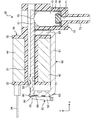
- the opening of the fluid passage portion is disposed closer to the suction portion of the yoke than the rotation axis of the movable iron piece, the relative positional relationship between the opening portion and the suction portion is less likely to vary, and the fluid A fluid passage opening / closing device capable of opening and closing the opening of the passage with high accuracy can be realized.
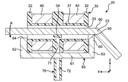
- the coil 40 is made of, for example, a magnet wire made of copper, and is wound around the body 31 of the spool 30, as shown in FIG. That is, the coil 40 is wound around the through hole 33 around the spool 30.
- the movable iron piece 50 is made of, for example, a plate-shaped metal having magnetism, extends along the first direction X, and is rotatable about a rotation shaft 90 as shown in FIG. It is housed in the through hole 33 of the spool 30.
- a suction unit 64 is provided so as to face the movable iron piece 50 in the second direction Y.
- the suction unit 64 has a substantially planar shape including the first direction X and the third direction Y, and is arranged so that the movable iron piece 50 can be sucked and rotated according to the energized state of the coil 40. .
- the opening 71 of the fluid passage 70 is disposed outside the spool 30 and adjacent to the suction unit 64 in the first direction X. With such a configuration, the opening 71 of the fluid passage 70 can be opened and closed with higher accuracy.
- the sphygmomanometer 1 includes the flow control device 5, for example, it is not necessary to separately provide a mechanism for controlling the flow rate of the fluid flowing through the fluid passage 70, and a sphygmomanometer with a simple configuration can be realized.
- the valve portion 76 is disposed so as to face the opening 71 of the fluid passage 70 and to be able to open and close the opening 71 by moving the plunger 73 in the second direction Y.
- FIG. 5 shows the fluid passage opening / closing device 20 during energization.
- the valve element 54 can be omitted.
- the other end in the extending direction of the first iron piece 51 on the plate surface of the movable iron piece 50 constitutes a lid that can open and close the opening 71 by the rotation of the movable iron piece 50.
- the fluid passage opening and closing device 20 includes:
- the movable iron piece 50 has a pivotally supported part 53 provided at one end in the extending direction thereof and constituting the pivot shaft 90,
- the yoke 60 has a third member 63 extending from the other end of the first member 61 in the extending direction toward the movable iron piece 50 along the second direction Y.
- a rotation support portion 65 is provided for rotatably supporting the movable iron piece 50 with the rotation supported portion 53.
- the flow control device 5 of the seventh aspect since the fluid passage opening / closing device 20 is provided, the flow control device 5 capable of controlling the flow rate of the fluid flowing through the fluid passage portion 70 through the opening 71 with high accuracy. Can be realized.
- the sphygmomanometer 1 includes: The flow control device 5 of the above embodiment is provided.
Landscapes
- Health & Medical Sciences (AREA)
- Engineering & Computer Science (AREA)
- Life Sciences & Earth Sciences (AREA)
- Physics & Mathematics (AREA)
- Vascular Medicine (AREA)
- Cardiology (AREA)
- General Engineering & Computer Science (AREA)
- Electromagnetism (AREA)
- Medical Informatics (AREA)
- Public Health (AREA)
- Biomedical Technology (AREA)
- Heart & Thoracic Surgery (AREA)
- Biophysics (AREA)
- Molecular Biology (AREA)
- Surgery (AREA)
- Animal Behavior & Ethology (AREA)
- General Health & Medical Sciences (AREA)
- Pathology (AREA)
- Veterinary Medicine (AREA)
- Physiology (AREA)
- Mechanical Engineering (AREA)
- Ophthalmology & Optometry (AREA)
- Power Engineering (AREA)
- Magnetically Actuated Valves (AREA)
- Measuring Pulse, Heart Rate, Blood Pressure Or Blood Flow (AREA)
Abstract
L'invention concerne un dispositif d'ouverture/fermeture de trajet de fluide comprenant : une bobine dans laquelle un trou traversant est ménagé ; une bobine enroulée autour du trou traversant de la bobine ; une pièce de fer mobile placée dans le trou traversant et pouvant tourner autour d'un axe de rotation ; une culasse qui comprend un premier élément et un second élément qui s'étend à partir d'une extrémité du premier élément dans la direction d'extension de ce dernier vers la pièce de fer mobile et dans lequel le second élément comprend une partie attraction conçue pour faire tourner la pièce de fer mobile en l'attirant en fonction de l'état de conduction de la bobine ; et une partie trajet de fluide comprenant une partie ouverture qui est disposée plus près de la partie attraction que de l'axe de rotation et au voisinage de la partie attraction.
Priority Applications (3)
| Application Number | Priority Date | Filing Date | Title |
|---|---|---|---|
| CN201980040925.XA CN112534170A (zh) | 2018-07-03 | 2019-02-06 | 流体通路开闭装置、流量控制装置以及血压计 |
| DE112019003364.6T DE112019003364T5 (de) | 2018-07-03 | 2019-02-06 | Fluidpfadöffnungs- und schliessvorrichtung, durchflusssteuervorrichtung und blutdruckmonitor |
| US17/257,675 US20210293346A1 (en) | 2018-07-03 | 2019-02-06 | Fluid path opening/closing device, flow rate control device, and blood pressure monitor |
Applications Claiming Priority (2)
| Application Number | Priority Date | Filing Date | Title |
|---|---|---|---|
| JP2018126811A JP2020008032A (ja) | 2018-07-03 | 2018-07-03 | 流体通路開閉装置、流量制御装置および血圧計 |
| JP2018-126811 | 2018-07-03 |
Publications (1)
| Publication Number | Publication Date |
|---|---|
| WO2020008671A1 true WO2020008671A1 (fr) | 2020-01-09 |
Family
ID=69059543
Family Applications (1)
| Application Number | Title | Priority Date | Filing Date |
|---|---|---|---|
| PCT/JP2019/004132 Ceased WO2020008671A1 (fr) | 2018-07-03 | 2019-02-06 | Dispositif d'ouverture/fermeture de trajet de fluide, dispositif de commande de débit et moniteur de pression sanguine |
Country Status (5)
| Country | Link |
|---|---|
| US (1) | US20210293346A1 (fr) |
| JP (1) | JP2020008032A (fr) |
| CN (1) | CN112534170A (fr) |
| DE (1) | DE112019003364T5 (fr) |
| WO (1) | WO2020008671A1 (fr) |
Families Citing this family (2)
| Publication number | Priority date | Publication date | Assignee | Title |
|---|---|---|---|---|
| DE102018206549B4 (de) * | 2018-04-27 | 2020-02-20 | Conti Temic Microelectronic Gmbh | Pneumatisches Magnetventil |
| CN118924270B (zh) * | 2023-05-11 | 2025-09-05 | 华为技术有限公司 | 电磁阀及可穿戴设备 |
Citations (6)
| Publication number | Priority date | Publication date | Assignee | Title |
|---|---|---|---|---|
| JPS553032U (fr) * | 1978-06-20 | 1980-01-10 | ||
| JPS5519878U (fr) * | 1978-07-26 | 1980-02-07 | ||
| JPS63237503A (ja) * | 1987-03-26 | 1988-10-04 | Matsushita Electric Works Ltd | 電磁石装置 |
| JPH0736405U (ja) * | 1993-12-13 | 1995-07-04 | 株式会社田村電機製作所 | 電磁石装置 |
| JP2002098253A (ja) * | 2000-07-13 | 2002-04-05 | Nass Magnet Gmbh | ソレノイドバルブ |
| JP2004251356A (ja) * | 2003-02-19 | 2004-09-09 | Seiko Epson Corp | 弁装置、液体噴射装置及び弁装置の制御方法 |
Family Cites Families (5)
| Publication number | Priority date | Publication date | Assignee | Title |
|---|---|---|---|---|
| JPS58185204U (ja) * | 1982-06-04 | 1983-12-09 | オムロン株式会社 | 血圧計用排気弁 |
| DE3834445A1 (de) * | 1988-10-10 | 1990-04-12 | Mesenich Gerhard | Elektromagnetisches einspritzventil mit kippanker |
| JP4511489B2 (ja) * | 2006-04-11 | 2010-07-28 | 日本精密測器株式会社 | 電動排気弁及び血圧計 |
| JP5364592B2 (ja) * | 2007-12-28 | 2013-12-11 | ホシデン株式会社 | ソレノイドバルブ |
| JP6248439B2 (ja) * | 2013-07-10 | 2017-12-20 | オムロンヘルスケア株式会社 | 電磁弁およびそれを備えた電子血圧計 |
-
2018
- 2018-07-03 JP JP2018126811A patent/JP2020008032A/ja active Pending
-
2019
- 2019-02-06 CN CN201980040925.XA patent/CN112534170A/zh active Pending
- 2019-02-06 DE DE112019003364.6T patent/DE112019003364T5/de not_active Ceased
- 2019-02-06 US US17/257,675 patent/US20210293346A1/en not_active Abandoned
- 2019-02-06 WO PCT/JP2019/004132 patent/WO2020008671A1/fr not_active Ceased
Patent Citations (6)
| Publication number | Priority date | Publication date | Assignee | Title |
|---|---|---|---|---|
| JPS553032U (fr) * | 1978-06-20 | 1980-01-10 | ||
| JPS5519878U (fr) * | 1978-07-26 | 1980-02-07 | ||
| JPS63237503A (ja) * | 1987-03-26 | 1988-10-04 | Matsushita Electric Works Ltd | 電磁石装置 |
| JPH0736405U (ja) * | 1993-12-13 | 1995-07-04 | 株式会社田村電機製作所 | 電磁石装置 |
| JP2002098253A (ja) * | 2000-07-13 | 2002-04-05 | Nass Magnet Gmbh | ソレノイドバルブ |
| JP2004251356A (ja) * | 2003-02-19 | 2004-09-09 | Seiko Epson Corp | 弁装置、液体噴射装置及び弁装置の制御方法 |
Also Published As
| Publication number | Publication date |
|---|---|
| US20210293346A1 (en) | 2021-09-23 |
| CN112534170A (zh) | 2021-03-19 |
| JP2020008032A (ja) | 2020-01-16 |
| DE112019003364T5 (de) | 2021-03-18 |
Similar Documents
| Publication | Publication Date | Title |
|---|---|---|
| US20150069860A1 (en) | Electrodynamic Actuator | |
| JP5613731B2 (ja) | ロータリソレノイド | |
| US20130229245A1 (en) | Driving device and relay | |
| JP2013190705A (ja) | 絞り羽根駆動装置 | |
| WO2020008671A1 (fr) | Dispositif d'ouverture/fermeture de trajet de fluide, dispositif de commande de débit et moniteur de pression sanguine | |
| JP4511489B2 (ja) | 電動排気弁及び血圧計 | |
| US5321377A (en) | Electromagnet for relays and contactor assemblies | |
| JP2015121289A (ja) | 電磁弁装置 | |
| US4134090A (en) | Electromagnetic actuator for a relay | |
| JP5521844B2 (ja) | 電磁石装置および電磁リレー | |
| JP2011141975A (ja) | 電磁石装置および電磁リレー | |
| JP2019143649A (ja) | 流体制御弁 | |
| JP2968745B2 (ja) | 回動アクチュエータ | |
| JP2020091003A (ja) | スプール式切換弁 | |
| CN107251386B (zh) | 发电装置 | |
| JP2000331824A (ja) | 電磁石装置 | |
| CN103681118B (zh) | 用于切换电磁继电器的工具及方法 | |
| JP2012175735A (ja) | ロータリーソレノイド | |
| JP3122718U (ja) | 電動排気弁及び血圧計 | |
| JP2017167213A (ja) | 羽根駆動装置 | |
| CN101310059A (zh) | 尤其用于织袜机等中的选择装置的磁致动器 | |
| JP2002108456A (ja) | 流体流量調節装置並びに血圧計用排気装置および血圧計 | |
| JP2009259612A (ja) | 双安定リレー | |
| WO2011111827A1 (fr) | Mécanisme de rétroaction et positionneur de soupape | |
| JPS5940612Y2 (ja) | 電磁比例制御弁 |
Legal Events
| Date | Code | Title | Description |
|---|---|---|---|
| 121 | Ep: the epo has been informed by wipo that ep was designated in this application |
Ref document number: 19829959 Country of ref document: EP Kind code of ref document: A1 |
|
| 122 | Ep: pct application non-entry in european phase |
Ref document number: 19829959 Country of ref document: EP Kind code of ref document: A1 |