WO2020008718A1 - Dispositif de maintien de capteur de couple - Google Patents
Dispositif de maintien de capteur de couple Download PDFInfo
- Publication number
- WO2020008718A1 WO2020008718A1 PCT/JP2019/018143 JP2019018143W WO2020008718A1 WO 2020008718 A1 WO2020008718 A1 WO 2020008718A1 JP 2019018143 W JP2019018143 W JP 2019018143W WO 2020008718 A1 WO2020008718 A1 WO 2020008718A1
- Authority
- WO
- WIPO (PCT)
- Prior art keywords
- torque sensor
- support
- torque
- sensor
- mounting portion
- Prior art date
- Legal status (The legal status is an assumption and is not a legal conclusion. Google has not performed a legal analysis and makes no representation as to the accuracy of the status listed.)
- Ceased
Links
Images



Classifications
-
- G—PHYSICS
- G01—MEASURING; TESTING
- G01L—MEASURING FORCE, STRESS, TORQUE, WORK, MECHANICAL POWER, MECHANICAL EFFICIENCY, OR FLUID PRESSURE
- G01L5/00—Apparatus for, or methods of, measuring force, work, mechanical power, or torque, specially adapted for specific purposes
- G01L5/0061—Force sensors associated with industrial machines or actuators
- G01L5/0076—Force sensors associated with manufacturing machines
-
- B—PERFORMING OPERATIONS; TRANSPORTING
- B25—HAND TOOLS; PORTABLE POWER-DRIVEN TOOLS; MANIPULATORS
- B25J—MANIPULATORS; CHAMBERS PROVIDED WITH MANIPULATION DEVICES
- B25J13/00—Controls for manipulators
- B25J13/08—Controls for manipulators by means of sensing devices, e.g. viewing or touching devices
- B25J13/085—Force or torque sensors
-
- G—PHYSICS
- G01—MEASURING; TESTING
- G01L—MEASURING FORCE, STRESS, TORQUE, WORK, MECHANICAL POWER, MECHANICAL EFFICIENCY, OR FLUID PRESSURE
- G01L3/00—Measuring torque, work, mechanical power, or mechanical efficiency, in general
- G01L3/02—Rotary-transmission dynamometers
- G01L3/14—Rotary-transmission dynamometers wherein the torque-transmitting element is other than a torsionally-flexible shaft
-
- G—PHYSICS
- G01—MEASURING; TESTING
- G01L—MEASURING FORCE, STRESS, TORQUE, WORK, MECHANICAL POWER, MECHANICAL EFFICIENCY, OR FLUID PRESSURE
- G01L3/00—Measuring torque, work, mechanical power, or mechanical efficiency, in general
- G01L3/02—Rotary-transmission dynamometers
- G01L3/14—Rotary-transmission dynamometers wherein the torque-transmitting element is other than a torsionally-flexible shaft
- G01L3/1407—Rotary-transmission dynamometers wherein the torque-transmitting element is other than a torsionally-flexible shaft involving springs
- G01L3/1428—Rotary-transmission dynamometers wherein the torque-transmitting element is other than a torsionally-flexible shaft involving springs using electrical transducers
- G01L3/1457—Rotary-transmission dynamometers wherein the torque-transmitting element is other than a torsionally-flexible shaft involving springs using electrical transducers involving resistance strain gauges
-
- G—PHYSICS
- G01—MEASURING; TESTING
- G01L—MEASURING FORCE, STRESS, TORQUE, WORK, MECHANICAL POWER, MECHANICAL EFFICIENCY, OR FLUID PRESSURE
- G01L5/00—Apparatus for, or methods of, measuring force, work, mechanical power, or torque, specially adapted for specific purposes
- G01L5/0061—Force sensors associated with industrial machines or actuators
-
- G—PHYSICS
- G01—MEASURING; TESTING
- G01D—MEASURING NOT SPECIALLY ADAPTED FOR A SPECIFIC VARIABLE; ARRANGEMENTS FOR MEASURING TWO OR MORE VARIABLES NOT COVERED IN A SINGLE OTHER SUBCLASS; TARIFF METERING APPARATUS; MEASURING OR TESTING NOT OTHERWISE PROVIDED FOR
- G01D11/00—Component parts of measuring arrangements not specially adapted for a specific variable
- G01D11/02—Bearings or suspensions for moving parts
-
- G—PHYSICS
- G01—MEASURING; TESTING
- G01D—MEASURING NOT SPECIALLY ADAPTED FOR A SPECIFIC VARIABLE; ARRANGEMENTS FOR MEASURING TWO OR MORE VARIABLES NOT COVERED IN A SINGLE OTHER SUBCLASS; TARIFF METERING APPARATUS; MEASURING OR TESTING NOT OTHERWISE PROVIDED FOR
- G01D11/00—Component parts of measuring arrangements not specially adapted for a specific variable
- G01D11/30—Supports specially adapted for an instrument; Supports specially adapted for a set of instruments
Definitions
- the embodiment of the present invention relates to a torque sensor applied to, for example, a robot arm or the like, and relates to a support device that supports the torque sensor.
- the torque sensor has a first structure to which a torque is applied, a second structure to which the torque is output, and a plurality of strain generating portions as beams connecting the first structure and the second structure.
- a plurality of strain gauges as sensor elements are arranged in these strain generating portions.
- a bridge circuit is configured by these strain gauges (see, for example, Patent Documents 1, 2, and 3).
- JP 2013-097735 A JP-A-2005-049209 JP, 2017-172983, A JP 2010-169586 A
- the torque sensor When the first structure of the disc-shaped torque sensor is fixed to, for example, a base portion of a robot arm (hereinafter, also simply referred to as an arm) and the second structure is fixed to, for example, a drive portion of the arm, the torque sensor is used. Is applied with a bending moment due to the transfer weight of the arm and the distance from the load to the load (the distance from the center of the torque sensor to the load) and the operating acceleration (inertia moment of the arm and the load).
- the point of force (or the point of action) is located on one side in the diameter direction of the torque sensor around the torque sensor, when the load is at 0 ° or 180 ° on the first axis, and when the load is on the second axis.
- the torque sensor does not receive interference from other axes, and the sensor output becomes zero.
- the torque sensor When the torque sensor is used for a robot arm, one end of the arm is fixed to the torque sensor side, and the other end is at a position away from the torque sensor. That is, when the torque sensor side is the fulcrum, the point of force (or the point of action) as a load is at a position distant from the fulcrum. In addition, the position of the load is not always on two orthogonal axes passing through the center of the disk-shaped torque sensor. For this reason, the torque sensor receives another axis interference due to the bending moment. In this case, a large other-axis interference occurs particularly with respect to a load at a position shifted by 45 ° from the first axis and the second axis.
- the embodiment of the present invention provides a torque sensor supporting device capable of preventing a bending moment other than torque from being generated in a torque sensor and improving detection accuracy of the torque sensor.
- the support device for a torque sensor includes a first structure, a second structure, a third structure provided between the first structure and the second structure, and a first structure.
- a torque sensor support device comprising: a structure and at least two sensor units provided between the second structure; a first mounting unit provided on the first structure; A second mounting portion connected to the second structure and to which a torque is applied, a first support provided on the first mounting portion, a second support interlocked with the second structure, A plurality of rotating bodies provided between the first support and the second support.
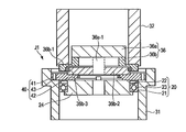
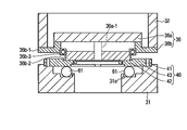
- FIG. 2 is a cross-sectional view illustrating an example of a torque sensor support device according to the first embodiment.
- FIG. 10 is a sectional view showing an example of a torque sensor support device according to the second embodiment.
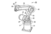
- FIG. 2 is a perspective view showing an example of a robot arm to which the embodiment is applied.
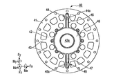
- FIG. 2 is a plan view showing an example of a torque sensor to which the embodiment is applied.
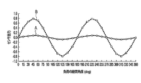
- FIG. 7 is a diagram illustrating a relationship between a rotation angle of a robot arm and a sensor output, and illustrates a comparison between the present embodiment and a comparative example. The figure shown for demonstrating the bending moment which arises in a torque sensor.
- FIG. 13 is a sectional view showing an example of a torque sensor support device according to a third embodiment. Sectional drawing which shows an example of the support apparatus of the torque sensor which concerns on 4th Embodiment.
- FIG. 3 shows an example of an articulated robot, that is, a robot arm 30.
- the robot arm 30 includes, for example, a base 31, a first arm 32, a second arm 33, a third arm 34, a fourth arm 35, a first drive unit 36, a second drive unit 37 as a drive source, and a third drive unit. 38, and a fourth driving unit 39.
- the configuration of the robot arm 30 is not limited to this, and can be deformed.
- the first arm 32 is rotatable with respect to the base 31 by the first drive unit 36 provided on the first joint J1.
- the second arm 33 is rotatable with respect to the first arm 32 by a second driving unit 37 provided at the second joint J2.
- the third arm 34 is rotatable with respect to the second arm 33 by a third drive unit 38 provided at the third joint J3.
- the fourth arm 35 is rotatably provided with respect to the third arm 34 by a fourth drive unit 39 provided at the fourth joint J4. Hands and various tools (not shown) are mounted on the fourth arm 35.
- the first to fourth driving units 36 to 39 include, for example, a motor, a reduction gear, and a torque sensor, which will be described later.
- FIG. 4 shows an example of a disk-shaped torque sensor 40 applied to the present embodiment.
- the torque sensor 40 includes a first structure 41, a second structure 42, a plurality of third structures 43, a first strain sensor 44 and a second strain sensor 45 as a sensor unit, and the like.
- the first structure 41 and the second structure 42 are formed in a ring shape, and the diameter of the second structure 42 is smaller than the diameter of the first structure 41.
- the second structure 42 is arranged concentrically with the first structure 41, and the first structure 41 and the second structure 42 are connected by a third structure 43 as a plurality of radially arranged beams. Have been.
- the plurality of third structures 43 transmit torque between the first structure 41 and the second structure 42.
- the second structure 42 has a hollow portion 42a, and, for example, a wiring (not shown) is passed through the hollow portion 42a.
- the first structure 41, the second structure 42, and the plurality of third structures 43 are made of metal, for example, stainless steel. However, as long as mechanical strength sufficient for applied torque can be obtained. It is also possible to use materials other than metals.
- the first structure 41, the second structure 42, and the plurality of third structures 43 have, for example, the same thickness.
- the mechanical strength of the torque sensor 40 is set by the thickness, width, and length of the third structure 43.
- a first strain sensor 44 and a second strain sensor 45 are provided between the first structure 41 and the second structure 42. Specifically, one end of a strain body 44a forming the first strain sensor 44 and one end of a strain body 45a forming the second strain sensor 45 are joined to the first structure 41, and the strain body 44a, The other end of 45a is joined to the second structure 42.
- the thickness of the strain bodies 44a and 45a is smaller than the thickness of the first structure 41, the second structure 42, and the plurality of third structures 43.
- a plurality of unillustrated strain gauges as sensor elements are provided on the surfaces of the strain generating bodies 44a and 45a, respectively.
- a first bridge circuit is configured by the sensor element provided on the strain body 44a, and a second bridge circuit is configured by the sensor element provided on the strain body 45a. That is, the torque sensor 40 includes two bridge circuits.
- the first strain sensor 44 and the second strain sensor 45 are arranged symmetrically with respect to the center of the first structure 41 and the second structure 42 (the center of action of torque). In other words, the first strain sensor 44 and the second strain sensor 45 are arranged on the diameter of the first and second annular structures 41 and 42.
- the first strain sensor 44 (strain body 44a) is connected to the flexible board 46
- the second strain sensor 45 (strain body 45a) is connected to the flexible board 47.
- the flexible boards 46 and 47 are connected to a printed board (not shown) covered by a cover 48.
- An operational amplifier for amplifying the output voltages of the two bridge circuits is disposed on the printed circuit board. Since the circuit configuration is not the essence of the present embodiment, the description is omitted.
- the torque sensor 40 is deformed with respect to the torque (Mz), and the deformation of the bending moment other than the torque (Mx, My) is suppressed by the support device described later.
- FIG. 1 shows a first embodiment.
- a first driving unit 36 As shown in FIG. 1, for example, in a first joint J ⁇ b> 1, a first driving unit 36, a torque sensor 40, and a rolling bearing as a support device for supporting the torque sensor 40, for example, a ball bearing (hereinafter, referred to as a bearing) ) 20 are provided.
- a ball bearing hereinafter, referred to as a bearing
- the torque sensor 40 is provided on the upper part of the base 31 as a first mounting part. Specifically, the first structure 41 of the torque sensor 40 is fixed to an upper portion of the base 31 by a plurality of bolts (not shown).
- the first drive unit 36 is provided on the first surface (front surface) of the torque sensor 40 inside the first arm 32 as the second attachment unit.
- the first drive unit 36 is configured by, for example, a motor 36a and a speed reducer 36b.
- the speed reducer 36b includes, for example, a case 36b-1, an output shaft 36b-2, a bearing 36b-3, and a plurality of gears (not shown).
- the output shaft 36b-2 is connected to the shaft 36a-1 of the motor 36a via a plurality of gears (not shown), and is provided rotatably with respect to the case 36b-1 by bearings 36b-3.
- the second structure 42 of the torque sensor 40 is fixed to the output shaft 36b-2 of the speed reducer 36b by a plurality of bolts (not shown).
- the case 36b-1 of the speed reducer 36b is fixed to the first arm 32.
- the bearing 20 includes an outer ring 21 as a first support, an inner ring 22 as a second support, and a plurality of balls 23 as a third support.
- the bearing 20 is provided on the first surface (front surface) side of the torque sensor 40.
- the outer ring 21 of the bearing 20 is fixed to the base 31, and the inner ring 22 is fixed to the case 36b-1 of the speed reducer 36b.
- FIG. 1 shows a case where a so-called radial bearing is applied as the bearing 20.
- the present invention is not limited to this, and it is also possible to apply a bearing having another configuration such as a thrust bearing.
- the third support is not limited to the ball 23 but may be a rotating body such as a roller.
- the bearing 20 When the bearing 20 receives a force in the direction in which the inner ring 22 rotates with respect to the outer ring 21, the inner ring 22 rotates with respect to the outer ring 21. On the other hand, when the bearing 20 receives a force other than the rotation direction, the deformation is suppressed by the rigidity of the outer ring 21, the inner ring 22, and the ball 23.
- the material of the ball 23 and the roller as the rotating body is a material containing iron, for example, a steel material such as stainless steel, cast iron, or ceramics.
- the number of balls 23 and rollers as rotating bodies is four or more, and the rotating bodies are arranged at equal intervals. These balls 23 and rollers are respectively arranged on the same radius.
- each rotating body is located at 45 °, 135 °, 225 °, 315 ° with respect to the first strain sensor 44 of the torque sensor 40, for example. Be placed.
- the rigidity of the bearing 20 as a supporting device including the first support 21, the second support 22, and the ball 23 is equal to or higher than the rigidity of the third structure 43 of the torque sensor 40.
- the outer ring 21 of the bearing 20 as a supporting device is fixed to the base 31 of the robot arm 30 to which the first structure 41 of the torque sensor 40 is fixed, and the inner ring 22 is fixed to the torque sensor 40.
- the second structure 42 is fixed to the fixed speed reducer 36 b and the first arm 32. Therefore, the bearing 20 can suppress the displacement of the torque sensor 40 due to a bending moment other than the torque with respect to the torque sensor 40. Therefore, the torque sensor 40 can suppress interference with other axes, and can improve the accuracy of torque detection by the torque sensor 40.
- FIG. 5 shows the relationship between the rotation angle (load setting angle) of the robot arm 30 with respect to the base 31 and the output signal of the torque sensor 40.
- a and a bearing as a support device are shown.
- B is shown.
- the robot arm 30 is rotatable 360 ° around the torque sensor 40.
- the bearing 20 when the bearing 20 is provided as in the first embodiment, the bearing 20 can suppress the displacement of the torque sensor 40 due to a force in a direction other than the torque applied to the torque sensor 40.
- the other axis interference can be suppressed in the torque sensor 40, as shown in FIG. 5A, at 45 °, 135 °, 225 °, 315 ° with respect to the first axis, the torque sensor 40 Generation of a sensor output can be suppressed. Therefore, it is possible to improve the accuracy of torque detection by the torque sensor 40.
- FIG. 2 shows a second embodiment.
- the second embodiment is a modification of the first embodiment.
- the bearing 20 as a support device is provided between the base 31 and the speed reducer 36b and the first arm 32 on the first surface (front surface) side of the torque sensor 40.
- the bearing 20 is provided on the second surface (back surface) side of the torque sensor 40.
- the bearing 20 is provided on the second surface side of the torque sensor 40 with the fourth support 24 interposed therebetween.
- the fourth support 24 has, for example, a circular shape having substantially the same diameter as the second structure 42 of the torque sensor 40 and is made of the same material as the torque sensor 40.
- the fourth support 24 is fixed to the second structure 42 of the torque sensor 40 by, for example, a bolt (not shown).
- the bearing 20 is provided between the periphery of the fourth support 24 and the inner surface of the base 31. That is, the inner ring 22 of the bearing 20 is fixed around the fourth support 24, and the outer ring 21 is fixed to the inner surface of the base 31.
- bearing 20 is not limited to a radial bearing, and a bearing having another configuration such as a thrust bearing can be used.
- the third support is not limited to the ball 23 but may be a rotating body such as a roller.
- the torque is The displacement of the second structure 42 of the sensor 40 is suppressed by the fourth support 24 and the bearing 20. Therefore, displacement of the second structure 42 of the torque sensor 40 with respect to the first structure 41 due to a bending moment other than the torque (Mx, My) is suppressed. Therefore, the output of the detection signal for the bending moment other than the torque (Mx, My) by the torque sensor 40 is suppressed.
- the fourth support 24 and the bearing 20 are provided between the second structure 42 and the base 31 on the second surface side of the torque sensor 40.
- the torque sensor 40 can suppress other-axis interference, and can suppress generation of a sensor output from the torque sensor 40 as shown in FIG. Therefore, it is possible to improve the accuracy of torque detection by the torque sensor 40.
- the torque sensor 40 is not subjected to a bending moment (Mx, My) other than the torque with respect to the torque sensor 40. Can be reliably prevented.
- the first structure 41 of the torque sensor 40 is connected to the base 31, and the second structure 42 is connected to the output shaft 36b-2 of the speed reducer 36b.
- the first structure 41 of the torque sensor 40 is connected to the output shaft 36b-2 of the speed reducer 36b, and the second structure 42 is connected to the base 31.
- one end of a cylindrical attachment 51a is fixed to the first structure 41 of the torque sensor 40 by, for example, a plurality of bolts (not shown).
- a case 36b-1 of the speed reducer 36b is fixed to the other end of the attachment 51a by, for example, a plurality of bolts (not shown).
- the output shaft 36b-2 of the speed reducer 36b is provided on the case 36b-1 via a bearing 36b-3, and is fixed to the first arm 32. Further, the output shaft 36b-2 is connected to a shaft 36a-1 of a motor 36a via a plurality of gears (not shown), and the motor 36a is provided in a case 36b-1.
- the second structure 42 of the torque sensor 40 is fixed to the base 31 by, for example, a plurality of bolts (not shown).
- the base 31 is connected to, for example, a cylindrical attachment 51b via a bearing 20 as a support, and one end of the attachment 51b is fixed to the first structure 41 of the torque sensor 40 by, for example, a plurality of bolts (not shown). ing.
- the bearing 20 is provided as a support device.
- a fourth embodiment shown in FIG. 8 is a modification of the first embodiment, and includes a groove 31a provided in a base 31 as a support device and a plurality of balls provided in the groove 31a.
- a roller is used.
- the configurations of the torque sensor 40, the motor 36a, the speed reducer 36b, and the first arm 32 are the same as those in the first embodiment. That is, the second structure 42 of the torque sensor 40 is fixed to the output shaft 36b-2 of the speed reducer 36b by a bolt (not shown).
- the first structure 41 of the torque sensor 40 is fixed to the base 31 with a plurality of bolts (not shown).
- an annular groove 31a is provided corresponding to the second structure 42 of the torque sensor 40, and a plurality of balls 61 as a rotating body are provided in the groove 31a.
- the ball 61 for example, a steel ball having sufficient rigidity can be used, and the ball 61 is in contact with the second structure 42 of the torque sensor 40 and is rotatable in the groove 31a.
- the rotating body is not limited to the ball 61, and a roller that can rotate in the groove 31a and can contact the second structure 42 of the torque sensor 40 can be applied.
- the torque is The deformation of the second structure 42 of the sensor 40 is suppressed by the rigidity of the plurality of balls 61. For this reason, the displacement of the second structure 42 with respect to the first structure 41 of the torque sensor 40 is suppressed with respect to the bending moment other than the torque (Mx, My). Therefore, the output of the detection signal for the bending moment other than the torque (Mx, My) by the torque sensor 40 is suppressed.
- the bearing 20 is provided on the base 31 of the first joint J1.
- the present invention is not limited to the first joint J1, and the bearing 20 may be applied to the second to fourth joints J2 to J4. It is possible.
- the bearing 20 is applied to the second to fourth joints J2 to J4, the same effect as when the bearing 20 is provided for the first joint J1 can be obtained.
- the torque sensor 40 has two sensor units of the first strain sensor 44 and the second strain sensor 45 has been described.
- the present invention is not limited to this, and any configuration may be used as long as it is possible to obtain three pieces of axis information of Mx, My, and Mz necessary for suppressing other axis interference. Therefore, the first to fourth embodiments can be applied to a torque sensor that can obtain information of three or less axes.
- the present invention is not limited to the above embodiments as they are, and may be embodied by modifying the components without departing from the scope of the invention at the stage of implementation.
- Various inventions can be formed by appropriately combining a plurality of constituent elements disclosed in the above embodiments. For example, some components may be deleted from all the components shown in the embodiment. Further, components of different embodiments may be appropriately combined.
Landscapes
- Engineering & Computer Science (AREA)
- Physics & Mathematics (AREA)
- General Physics & Mathematics (AREA)
- Chemical & Material Sciences (AREA)
- Analytical Chemistry (AREA)
- Human Computer Interaction (AREA)
- Robotics (AREA)
- Mechanical Engineering (AREA)
- Manipulator (AREA)
- Force Measurement Appropriate To Specific Purposes (AREA)
- Power Steering Mechanism (AREA)
Abstract
L'invention concerne un dispositif de maintien de capteur de couple permettant d'empêcher un capteur de couple d'être soumis à un moment de flexion sans couple et d'améliorer la précision de détection du capteur de couple. Dans ledit dispositif de maintien de capteur de couple, un premier corps de maintien (21) est situé sur une base (31) servant de première partie de fixation pour un robot. Un second corps de maintien (22) est accouplé à un deuxième corps structural (42) d'un capteur de couple (40) qui comprend : un premier corps structural (41) situé sur la base (31) ; le deuxième corps structural (42) relié à un premier bras (32) servant de seconde partie de fixation ; un troisième corps structural (43) situé entre le premier corps structural et le deuxième corps structural ; et au moins deux parties de capteur (44, 45) situées entre le premier corps structural et le second corps structural. Un corps rotatif (23) est situé entre le premier corps de maintien (21) et le second corps de maintien (22).
Priority Applications (3)
| Application Number | Priority Date | Filing Date | Title |
|---|---|---|---|
| CN201980044020.XA CN112513602B (zh) | 2018-07-02 | 2019-04-26 | 扭矩传感器的支承装置 |
| EP19830849.6A EP3819617B1 (fr) | 2018-07-02 | 2019-04-26 | Dispositif de maintien de capteur de couple |
| US17/138,294 US11345044B2 (en) | 2018-07-02 | 2020-12-30 | Torque sensor supporting device |
Applications Claiming Priority (2)
| Application Number | Priority Date | Filing Date | Title |
|---|---|---|---|
| JP2018126141A JP6910991B2 (ja) | 2018-07-02 | 2018-07-02 | トルクセンサの支持装置 |
| JP2018-126141 | 2018-07-02 |
Related Child Applications (1)
| Application Number | Title | Priority Date | Filing Date |
|---|---|---|---|
| US17/138,294 Continuation US11345044B2 (en) | 2018-07-02 | 2020-12-30 | Torque sensor supporting device |
Publications (1)
| Publication Number | Publication Date |
|---|---|
| WO2020008718A1 true WO2020008718A1 (fr) | 2020-01-09 |
Family
ID=69060931
Family Applications (1)
| Application Number | Title | Priority Date | Filing Date |
|---|---|---|---|
| PCT/JP2019/018143 Ceased WO2020008718A1 (fr) | 2018-07-02 | 2019-04-26 | Dispositif de maintien de capteur de couple |
Country Status (6)
| Country | Link |
|---|---|
| US (1) | US11345044B2 (fr) |
| EP (1) | EP3819617B1 (fr) |
| JP (1) | JP6910991B2 (fr) |
| CN (1) | CN112513602B (fr) |
| TW (1) | TWI804625B (fr) |
| WO (1) | WO2020008718A1 (fr) |
Families Citing this family (4)
| Publication number | Priority date | Publication date | Assignee | Title |
|---|---|---|---|---|
| JP6910990B2 (ja) * | 2018-07-02 | 2021-07-28 | 日本電産コパル電子株式会社 | トルクセンサの支持装置 |
| CN112798151B (zh) * | 2021-01-26 | 2024-09-20 | 松诺盟科技有限公司 | 扭矩传感器力臂结构及扭矩传感器 |
| JP7817088B2 (ja) * | 2022-06-07 | 2026-02-18 | ヤマハ発動機株式会社 | 起歪体およびこれを備えた作業ロボット |
| JP2023183228A (ja) * | 2022-06-15 | 2023-12-27 | I-Pex株式会社 | トルクセンサ |
Citations (6)
| Publication number | Priority date | Publication date | Assignee | Title |
|---|---|---|---|---|
| JP2005069402A (ja) * | 2003-08-26 | 2005-03-17 | Harmonic Drive Syst Ind Co Ltd | トルク検出機構付き波動歯車装置 |
| JP2010169586A (ja) | 2009-01-23 | 2010-08-05 | Minebea Co Ltd | トルク量変換器 |
| JP2013096735A (ja) | 2011-10-28 | 2013-05-20 | Toyota Motor Corp | 起歪体及びトルクセンサ |
| JP2015049209A (ja) | 2013-09-04 | 2015-03-16 | トヨタ自動車株式会社 | トルクセンサ |
| JP2017172983A (ja) | 2016-03-18 | 2017-09-28 | 株式会社安川電機 | ロボット及びトルクセンサ |
| JP2018091813A (ja) * | 2016-12-07 | 2018-06-14 | 日本電産コパル電子株式会社 | トルクセンサ |
Family Cites Families (26)
| Publication number | Priority date | Publication date | Assignee | Title |
|---|---|---|---|---|
| US4754652A (en) * | 1986-11-04 | 1988-07-05 | General Electric Company | Apparatus for measuring torque |
| GB2238623A (en) * | 1989-11-24 | 1991-06-05 | Mecmesin Ltd | Torque measuring apparatus |
| JPH05223665A (ja) * | 1992-02-18 | 1993-08-31 | Fujitsu Ltd | モータのトルク検出部 |
| JPH1194662A (ja) * | 1997-09-16 | 1999-04-09 | Shin Nikkei Co Ltd | ネジの締付力及び締付トルク測定装置 |
| JP3861478B2 (ja) * | 1998-11-02 | 2006-12-20 | 株式会社明電舎 | 鉄道車両用ブレーキ試験装置 |
| JP5180483B2 (ja) * | 2006-03-28 | 2013-04-10 | 本田技研工業株式会社 | トルクセンサの製造方法 |
| JP2009288198A (ja) * | 2008-05-30 | 2009-12-10 | Sony Corp | トルク計測装置並びにアクチュエータ駆動制御システム |
| JP2011209099A (ja) * | 2010-03-30 | 2011-10-20 | Sony Corp | トルクセンサおよびロボット装置 |
| CN101865275B (zh) * | 2010-05-28 | 2012-10-24 | 上海应用技术学院 | 与减速器组合在一起的扭矩传感器 |
| JP4963134B2 (ja) * | 2010-11-25 | 2012-06-27 | 株式会社トライフォース・マネジメント | トルクセンサ |
| KR101921173B1 (ko) * | 2011-04-12 | 2018-11-22 | 고쿠사이 게이소쿠키 가부시키가이샤 | 회전 비틀림 시험기 |
| DE102011085299A1 (de) * | 2011-10-27 | 2013-05-02 | Siemens Aktiengesellschaft | Getriebe für industrielle Anwendungen oder Windkraftanlagen |
| EP2775270A4 (fr) * | 2011-10-31 | 2015-08-26 | Nsk Ltd | Capteur optique, procédé de production de capteurs optiques, codeur optique, dispositif de détection de couple et dispositif de direction assistée électrique |
| US9293962B2 (en) * | 2012-03-30 | 2016-03-22 | Korea Institute Of Machinery & Materials | Hollow driving module |
| WO2014110682A1 (fr) * | 2013-01-18 | 2014-07-24 | Robotiq Inc. | Capteur de force/couple, appareil et procédé pour apprentissage et fonctionnement de robot |
| US10012334B2 (en) * | 2013-03-28 | 2018-07-03 | Fujikin Incorporated | Structure for attaching pressure detector |
| JP6402719B2 (ja) * | 2013-11-05 | 2018-10-10 | 日本精工株式会社 | 力覚センサ |
| DE202013105036U1 (de) * | 2013-11-08 | 2015-02-10 | Daimler Ag | Erfassungseinrichtung |
| TWI539142B (zh) * | 2014-10-23 | 2016-06-21 | Torque measuring mechanism | |
| JP6500649B2 (ja) * | 2014-11-19 | 2019-04-17 | 日本精工株式会社 | トルク測定装置付回転伝達装置 |
| CN204239655U (zh) * | 2014-11-19 | 2015-04-01 | 中国科学院沈阳自动化研究所 | 能够测量输出扭矩的柔性传动装置 |
| US9751220B2 (en) * | 2015-03-31 | 2017-09-05 | Google Inc. | Flexure based torque sensor |
| CN204831658U (zh) * | 2015-05-07 | 2015-12-02 | 晋西工业集团有限责任公司 | 一种抗高弯矩的扭矩测量装置 |
| US10422707B2 (en) * | 2016-01-19 | 2019-09-24 | Ati Industrial Automation, Inc. | Compact robotic force/torque sensor including strain gages |
| US10295419B2 (en) * | 2016-02-24 | 2019-05-21 | Toyota Jidosha Kabushiki Kaisha | Actuator |
| CN106826906B (zh) * | 2017-02-27 | 2019-03-05 | 哈尔滨工业大学深圳研究生院 | 一种无力矩传感器的机械臂模块化关节 |
-
2018
- 2018-07-02 JP JP2018126141A patent/JP6910991B2/ja active Active
-
2019
- 2019-04-26 WO PCT/JP2019/018143 patent/WO2020008718A1/fr not_active Ceased
- 2019-04-26 EP EP19830849.6A patent/EP3819617B1/fr active Active
- 2019-04-26 CN CN201980044020.XA patent/CN112513602B/zh active Active
- 2019-05-15 TW TW108116722A patent/TWI804625B/zh active
-
2020
- 2020-12-30 US US17/138,294 patent/US11345044B2/en active Active
Patent Citations (6)
| Publication number | Priority date | Publication date | Assignee | Title |
|---|---|---|---|---|
| JP2005069402A (ja) * | 2003-08-26 | 2005-03-17 | Harmonic Drive Syst Ind Co Ltd | トルク検出機構付き波動歯車装置 |
| JP2010169586A (ja) | 2009-01-23 | 2010-08-05 | Minebea Co Ltd | トルク量変換器 |
| JP2013096735A (ja) | 2011-10-28 | 2013-05-20 | Toyota Motor Corp | 起歪体及びトルクセンサ |
| JP2015049209A (ja) | 2013-09-04 | 2015-03-16 | トヨタ自動車株式会社 | トルクセンサ |
| JP2017172983A (ja) | 2016-03-18 | 2017-09-28 | 株式会社安川電機 | ロボット及びトルクセンサ |
| JP2018091813A (ja) * | 2016-12-07 | 2018-06-14 | 日本電産コパル電子株式会社 | トルクセンサ |
Also Published As
| Publication number | Publication date |
|---|---|
| EP3819617A4 (fr) | 2022-03-23 |
| JP2020003460A (ja) | 2020-01-09 |
| US20210114230A1 (en) | 2021-04-22 |
| CN112513602A (zh) | 2021-03-16 |
| EP3819617B1 (fr) | 2024-08-21 |
| TW202016522A (zh) | 2020-05-01 |
| US11345044B2 (en) | 2022-05-31 |
| CN112513602B (zh) | 2022-06-21 |
| TWI804625B (zh) | 2023-06-11 |
| JP6910991B2 (ja) | 2021-07-28 |
| EP3819617A1 (fr) | 2021-05-12 |
Similar Documents
| Publication | Publication Date | Title |
|---|---|---|
| WO2020008718A1 (fr) | Dispositif de maintien de capteur de couple | |
| JP6910990B2 (ja) | トルクセンサの支持装置 | |
| US8251863B2 (en) | Continuously variable transmission with multiple outputs | |
| TWI811395B (zh) | 轉矩感測器之安裝構造 | |
| CN111936276A (zh) | 关节单元、机械臂以及机器人 | |
| TWI798444B (zh) | 轉矩感測器之安裝構造 | |
| JP2019162699A (ja) | ロボットのアーム構造およびロボット | |
| JP7746430B2 (ja) | 駆動装置、ロボット、制御方法、検出装置、物品の製造方法、処理方法、プログラム、記録媒体 | |
| JP7066560B2 (ja) | トルクセンサの取り付け構造 | |
| JP7200058B2 (ja) | トルクセンサの取り付け構造 | |
| JP2020012657A (ja) | トルクセンサ | |
| JP2020012658A (ja) | トルクセンサ | |
| JP2007085559A (ja) | 撓み噛み合い式減速機 | |
| JP7091177B2 (ja) | トルクセンサ | |
| JP4401872B2 (ja) | 位置制御装置 | |
| JPH08152027A (ja) | たわみ軸継手 |
Legal Events
| Date | Code | Title | Description |
|---|---|---|---|
| 121 | Ep: the epo has been informed by wipo that ep was designated in this application |
Ref document number: 19830849 Country of ref document: EP Kind code of ref document: A1 |
|
| NENP | Non-entry into the national phase |
Ref country code: DE |
|
| ENP | Entry into the national phase |
Ref document number: 2019830849 Country of ref document: EP Effective date: 20210202 |