WO2020008748A1 - 誘電体導波管フィルタ - Google Patents
誘電体導波管フィルタ Download PDFInfo
- Publication number
- WO2020008748A1 WO2020008748A1 PCT/JP2019/020291 JP2019020291W WO2020008748A1 WO 2020008748 A1 WO2020008748 A1 WO 2020008748A1 JP 2019020291 W JP2019020291 W JP 2019020291W WO 2020008748 A1 WO2020008748 A1 WO 2020008748A1
- Authority
- WO
- WIPO (PCT)
- Prior art keywords
- dielectric waveguide
- resonator
- coupling
- coupling portion
- main
- Prior art date
- Legal status (The legal status is an assumption and is not a legal conclusion. Google has not performed a legal analysis and makes no representation as to the accuracy of the status listed.)
- Ceased
Links
Images



Classifications
-
- H—ELECTRICITY
- H01—ELECTRIC ELEMENTS
- H01P—WAVEGUIDES; RESONATORS, LINES, OR OTHER DEVICES OF THE WAVEGUIDE TYPE
- H01P1/00—Auxiliary devices
- H01P1/20—Frequency-selective devices, e.g. filters
- H01P1/2002—Dielectric waveguide filters
-
- H—ELECTRICITY
- H01—ELECTRIC ELEMENTS
- H01P—WAVEGUIDES; RESONATORS, LINES, OR OTHER DEVICES OF THE WAVEGUIDE TYPE
- H01P1/00—Auxiliary devices
- H01P1/20—Frequency-selective devices, e.g. filters
- H01P1/207—Hollow waveguide filters
- H01P1/208—Cascaded cavities; Cascaded resonators inside a hollow waveguide structure
- H01P1/2088—Integrated in a substrate
-
- H—ELECTRICITY
- H01—ELECTRIC ELEMENTS
- H01P—WAVEGUIDES; RESONATORS, LINES, OR OTHER DEVICES OF THE WAVEGUIDE TYPE
- H01P3/00—Waveguides; Transmission lines of the waveguide type
- H01P3/16—Dielectric waveguides, i.e. without a longitudinal conductor
-
- H—ELECTRICITY
- H01—ELECTRIC ELEMENTS
- H01P—WAVEGUIDES; RESONATORS, LINES, OR OTHER DEVICES OF THE WAVEGUIDE TYPE
- H01P7/00—Resonators of the waveguide type
- H01P7/10—Dielectric resonators
Definitions
- the present invention relates to a dielectric waveguide filter having a plurality of dielectric waveguide resonators.
- a dielectric waveguide filter having a plurality of dielectric waveguide resonators is disclosed in, for example, Patent Document 1.
- a coupling portion is formed between resonators such that adjacent dielectric waveguide resonators are coupled to each other.
- inductive coupling is used for coupling between the resonators constituting the main coupling path, but if the main coupling path is composed only of inductive coupling, the attenuation characteristic from the passband to the high band is gentle. Become. Therefore, when steepness is required for the attenuation characteristic from the pass band to the high band, it is necessary to increase the number of resonators to be coupled, and as a result, the insertion loss in the pass band increases.
- the main coupling path is formed by capacitive coupling.
- a spurious response appears in a lower band than the pass band due to the capacitive coupling.
- an object of the present invention is to provide a dielectric waveguide filter which has a small number of resonators, sharpens the attenuation characteristics from the pass band to the high band, and suppresses spurious responses appearing in the lower band than the pass band. Is to do.
- a dielectric waveguide filter includes: a plurality of dielectric waveguide resonators arranged along a main coupling path of signal propagation; and a plurality of the dielectric waveguide resonators.
- a plurality of main coupling portions each provided between adjacent dielectric waveguide resonators along the main coupling path, wherein the plurality of main coupling portions are inductive coupling portions and capacitive coupling portions.
- a coupling portion, wherein the inductive coupling portion and the capacitive coupling portion are alternately and repeatedly arranged along the main coupling path.
- the main coupling path includes the capacitive coupling portion, a steep attenuation characteristic from the passband to the high band can be obtained with a small number of resonators.
- the capacitively coupled dielectric waveguide resonator is not continuous in two or more steps along the main coupling path, that is, the capacitive coupling section is sandwiched between the inductive coupling sections along the main coupling path. Excitation of low-order modes due to capacitive coupling is suppressed without being noticeable. For this reason, spurious responses appearing in a region lower than the pass band are suppressed.
- the present invention it is possible to obtain a dielectric waveguide filter with a small number of resonator stages, in which the attenuation characteristics from the pass band to the high band are sharp, and the spurious response appearing in the lower band than the pass band is suppressed.
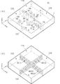
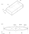
- FIG. 1A is an external perspective view of the dielectric waveguide filter 101 according to the first embodiment
- FIG. 1B is a transparent perspective view showing the internal structure of the dielectric waveguide filter 101.
- FIG. 2A is an enlarged perspective view showing the configuration of the input / output post and the input / output pad
- FIG. 2B is an enlarged perspective view showing the configuration of the non-through posts 3U and 3L
- FIG. 3A is a perspective view showing four dielectric waveguide resonator portions included in the dielectric waveguide filter 101
- FIG. 3B is a main coupling portion included in the dielectric waveguide filter 101. It is a perspective view which shows a subjoining part.
- FIG. 1A is an external perspective view of the dielectric waveguide filter 101 according to the first embodiment
- FIG. 1B is a transparent perspective view showing the internal structure of the dielectric waveguide filter 101.
- FIG. 2A is an enlarged perspective view showing the configuration of the input / output post and the input / output pad
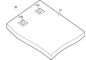
- FIG. 4 is a partial perspective view of a circuit board 90 on which the dielectric waveguide filter 101 is mounted.
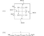
- FIGS. 5A and 5B are diagrams showing a coupling structure of four resonators constituting the dielectric waveguide filter 101.
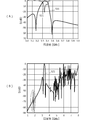
- FIG. FIGS. 6A and 6B are diagrams showing the frequency characteristics of the reflection characteristics and the pass characteristics of the dielectric waveguide filter 101.
- FIG. FIGS. 7A and 7B are schematic diagrams of a resonance system including two adjacent dielectric waveguide resonators R1 and R2.
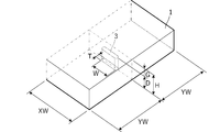
- FIG. 8 is a transparent perspective view showing the structure of a capacitive coupling portion formed by simplifying the non-penetrating post 3 shown in FIG. 2B.
- FIG. 8 is a transparent perspective view showing the structure of a capacitive coupling portion formed by simplifying the non-penetrating post 3 shown in FIG. 2B.
- FIG. 9 is a diagram showing the characteristics of each resonance mode when the horizontal axis represents the depth of the non-penetrating post 3 and the vertical axis represents the resonance frequency.
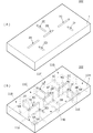
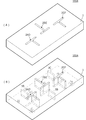
- FIG. 10A is an external perspective view of the dielectric waveguide filter 102 according to the second embodiment
- FIG. 10B is a transparent perspective view showing the internal structure of the dielectric waveguide filter 102.
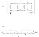
- FIGS. 11A and 11B are diagrams showing a coupling structure of eight resonators constituting the dielectric waveguide filter 102 of the present embodiment.
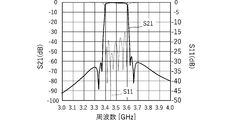
- FIG. 12 is a diagram showing the frequency characteristics of the reflection characteristics and the pass characteristics of the dielectric waveguide filter 102.
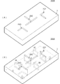
- FIG. 13A is an external perspective view of a dielectric waveguide filter 103A according to the third embodiment, and FIG.
- FIG. 13B is a transparent perspective view showing the internal structure of the dielectric waveguide filter 103A.
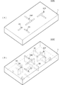
- FIG. 14A is an external perspective view of another dielectric waveguide filter 103B according to the third embodiment, and FIG. 14B is a transparent perspective view showing the internal structure of the dielectric waveguide filter 103B.
- FIG. 15A is an external perspective view of still another dielectric waveguide filter 103C according to the third embodiment, and FIG. 15B is a perspective view showing the internal structure of the dielectric waveguide filter 103C.
- FIG. FIGS. 16A and 16B are views showing a coupling structure of six resonators constituting a dielectric waveguide filter 104A according to the fourth embodiment.
- FIG. 17A and 17B are diagrams showing a coupling structure of six resonators constituting another dielectric waveguide filter 104B according to the fourth embodiment.
- FIG. 18A is an external perspective view of the dielectric waveguide filter 105 according to the fifth embodiment, and
- FIG. 18B is a transparent perspective view showing the internal structure of the dielectric waveguide filter 105.
- FIG. 19 is a block diagram of a mobile phone base station according to the sixth embodiment.
- FIG. 1A is an external perspective view of the dielectric waveguide filter 101 according to the first embodiment
- FIG. 1B is a transparent perspective view showing the internal structure of the dielectric waveguide filter 101.
- FIG. 2A is an enlarged perspective view illustrating the configuration of the input / output post and the input / output pad
- FIG. 2B is an enlarged perspective view illustrating the configuration of the non-through posts 3U and 3L
- FIG. 3A is a perspective view showing four dielectric waveguide resonator portions included in the dielectric waveguide filter 101
- FIG. It is a perspective view which shows a connection part and a sub connection part.
- This dielectric waveguide filter 101 is configured in a rectangular parallelepiped dielectric block 1.
- the dielectric block 1 is formed by processing dielectric ceramic, crystal, resin, or the like into a rectangular parallelepiped shape.
- Input / output pads 5A and 5B are formed on the bottom surface of the dielectric block 1.
- the dielectric block 1 is formed with input / output posts 4A, 4B protruding from the input / output pads 5A, 5B into the dielectric block 1.
- the dielectric block 1 is formed with through posts 2A to 2K penetrating from the upper surface to the lower surface.
- the dielectric block 1 is formed with a non-penetrating post 3U dug from the upper surface to a predetermined depth and a non-penetrating post 3L dug from the lower surface of the dielectric block 1 to a predetermined depth.
- a conductor film is formed on the inner surface of the outer surface of the dielectric block 1, each through post, and each non-through post.
- the periphery of the input / output pads 5A and 5B is separated from a conductor film used as a ground conductor.
- This conductive film is formed, for example, by metallizing an Ag electrode paste.
- the dielectric waveguide filter 101 includes four dielectric waveguide resonators 11A, 11B, 11C, and 11D.
- the dielectric waveguide resonator 11A is a first dielectric waveguide resonator according to the present invention
- the dielectric waveguide resonator 11B is a second dielectric waveguide resonator according to the present invention.
- the tube resonator 11C corresponds to a third dielectric waveguide resonator according to the present invention
- the dielectric waveguide resonator 11D corresponds to a fourth dielectric waveguide resonator according to the present invention.
- each of the resonators 11A, 11B, 11C, and 11D is a resonator having a TE101 mode as a fundamental mode.
- this is a resonance mode of an electromagnetic field distribution in which the magnetic field rotates in the plane direction along the XY plane with the Z direction as the electric field direction, and one electric field intensity peak in the X direction and one electric field intensity peak in the Y direction.
- a main coupling section MC12 is formed between the resonators 11A and 11B, a main coupling section MC23 is formed between the resonators 11B and 11C, and a main coupling section MC34 is formed between the resonators 11C and 11D.
- the sub-coupling portion SC14 is formed between the resonators 11A to 11D.
- the main joint MC12 shown in FIG. 3B is constituted by the through posts 2C, 2D and 2E shown in FIG. 3A.
- the main joint MC34 shown in FIG. 3B is constituted by the through posts 2C, 2J, and 2K shown in FIG.
- the sub-joining portion SC14 shown in FIG. 3B is constituted by the through posts 2A, 2B, and 2C shown in FIG.
- the main joint MC23 shown in FIG. 3B is constituted by the through posts 2F and 2G and the non-through posts 3U and 3L shown in FIG.
- the main coupling portion MC12 functions as an inductive coupling window for limiting the width (width in the Y direction) orthogonal to the electric field direction of the resonators 11A and 11B by the through posts 2C, 2D and 2E. They are inductively linked together.
- the main coupling portion MC34 acts as an inductive coupling window for limiting the width (width in the Y direction) orthogonal to the electric field direction of the resonators 11C and 11D by the through posts 2C, 2J and 2K. They are inductively linked together.
- the sub-coupling portion SC14 functions as an inductive coupling window for limiting the width (width in the X direction) orthogonal to the electric field direction of the resonators 11A and 11D by the through posts 2A, 2B and 2C. 11Ds are inductively linked.
- the gap between the non-penetrating post 3U and the non-penetrating post 3L is a capacitance that limits the width of the resonators 11B and 11C in the electric field direction (Z direction).
- the resonators 11B-11C are capacitively coupled to each other because they function as a capacitive coupling window.
- the through posts 2C, 2F, and 2G limit the width (width in the X direction) orthogonal to the electric field direction of the resonators 11B and 11C.
- the electric field direction (Z direction) by the non-through posts 3U and 3L is used.
- FIG. 4 is a partial perspective view of a circuit board 90 on which the dielectric waveguide filter 101 is mounted.
- the ground conductor 10 and the input / output lands 15A and 15B are formed on the circuit board 90.
- the input / output pads 5A and 5B of the dielectric waveguide filter 101 are connected to the input / output lands 15A and 15B.
- the ground conductor formed on the bottom surface of the waveguide filter 101 is connected to the ground conductor 10 of the circuit board 90.
- the circuit board 90 is formed with transmission lines such as strip lines, microstrip lines, and coplanar lines, which are connected to the input / output lands 15A and 15B.
- FIGS. 5A and 5B are views showing a coupling structure of four resonators constituting the dielectric waveguide filter 101 of the present embodiment.
- the resonator 11A is a first-stage (first-stage) resonator
- the resonator 11B is a second-stage resonator
- the resonator 11C is a third-stage resonator.
- the resonator 11D is a fourth-stage (final-stage) resonator.
- a path indicated by a double line is a main connection path, and a broken line is a sub-connection path.
- “L” represents inductive coupling
- “C” represents capacitive coupling.
- the resonators 11A, 11B, 11C, and 11D are arranged along a main coupling path for signal propagation, and the main coupling section MC12 is an inductive coupling section.
- MC23 is a capacitive coupling part, and main coupling part MC34 is an inductive coupling part. That is, the main coupling portion is composed of the inductive coupling portion and the capacitive coupling portion, and the inductive coupling portion and the capacitive coupling portion are alternately and repeatedly arranged along the main coupling path.
- the main coupling portion between the resonator 11A for inputting / outputting a signal to the outside and the resonator 11B coupled to the resonator 11A is inductive. It is a joint.
- a main coupling portion between a resonator 11D to which signals are input and output to and from the outside and a resonator 11C coupled to the resonator 11D is an inductive coupling portion.
- the resonators 11A and 11D are arranged along the sub-coupling path in addition to the main coupling path. That is, the sub-coupling portion SC14 is formed between the resonator 11A and the resonator 11D.
- the sub coupling SC14 is an inductive coupling, and the coupling of the sub coupling SC14 is weaker than the coupling of the main couplings MC12, MC23 and MC34.
- the absolute value of the coupling coefficient of the sub coupling unit SC14 is It is smaller than the absolute value of the coupling coefficient of the coupling portions MC12, MC23, and MC34.
- FIG. 6 (A) and 6 (B) are diagrams showing the frequency characteristics of the reflection characteristics and the pass characteristics of the dielectric waveguide filter 101.
- FIG. FIG. 6B has a wider range of the frequency axis than FIG. 6A.
- the dielectric waveguide filter 101 of the present embodiment has a pass band at 3.3 GHz to 3.4 GHz, has a lower attenuation pole at 3.17 GHz, It has a high-frequency attenuation pole at 3.48 GHz.
- the transmission phase of the resonator is delayed by 90 ° at a frequency lower than the resonance frequency of the resonator, and advanced by 90 ° at a frequency higher than the resonance frequency. Since the phases of the inductive coupling and the capacitive coupling are inverted, when the inductive coupling and the capacitive coupling are combined, the signal transmitted through the main coupling path and the signal transmitted through the sub coupling path have opposite phases and the same amplitude. There are certain frequencies. An attenuation pole appears at this frequency.
- the first resonator 11A and the second resonator 11B are inductively coupled
- the second resonator 11B and the third resonator 11C are capacitively coupled
- the third resonator 11C and the fourth resonator 11D are inductively coupled with each other and jump over the second resonator 11B and the third resonator 11C
- the first resonator 11A and the fourth resonator 11D are sub-coupled.
- the phase in the main coupling path from the first resonator 11A to the fourth resonator 11D and the phase in the sub coupling path from the first resonator 11A to the fourth resonator 11D is inverted in the low band of the pass band, and is also inverted in the high band. That is, attenuation poles appear in both the low band and the high band of the pass band.
- FIGS. 7A and 7B are schematic diagrams of a resonance system including two adjacent resonators R1 and R2.
- FIG. 7A is a perspective view of the resonance system
- FIG. 7B is a front view thereof.
- electric field waves of each mode of TE101, TE102, and TE103 are shown in a superimposed manner.
- there are resonance modes related to the propagation mode TE10 such as TE101, TE102, TE103,.
- the TE101 mode has an in-phase relationship between the resonator R1 and the resonator R2
- the resonance mode TE102 has an anti-phase relationship between the resonator R1 and the resonator R2
- the TE103 mode has a phase relationship between the resonator R1 and the resonator R2.
- the coupling between the TE101 mode (in-phase) and the TE102 mode (out-of-phase) is defined as inductive coupling
- the coupling between the TE102 mode (out-of-phase) and the TE103 mode (in-phase) is induced. Since the coupling has a relationship in which the phase is inverted with respect to the sexual coupling, it is capacitive coupling.
- the capacitive coupling is a coupling between the TE102 mode, which is a higher-order mode, and the TE103 mode, which is a higher-order mode
- the TE101 mode which is a lower-order resonance mode as spurious
- the inductive coupling is a coupling between the TE101 mode, which is the fundamental mode, and the TE102 mode, so that no spurious is generated on the lower frequency side than the pass band (because there are no lower-order modes). Therefore, by arranging the capacitive coupling portion between the inductive coupling portions along the main coupling path, a low-order spurious response due to the capacitive coupling is suppressed.
- FIG. 8 is a transparent perspective view showing the structure of a capacitive coupling portion formed by simplifying the non-penetrating post 3 shown in FIG. 2B.
- the protrusion height (depth) of the non-penetrating post 3 from the lower surface of the dielectric block 1 is represented by D
- the width is represented by W
- the thickness is represented by T.
- W 6.6 mm
- T 1.0 mm.
- the height H of each resonator is 5.5 mm
- the width XW in the X direction is 13 mm
- the width YW in the Y direction is 13 mm.
- FIG. 9 is a diagram showing the characteristics of each resonance mode when the horizontal axis indicates the depth of the non-penetrating post 3 and the vertical axis indicates the resonance frequency.
- the frequency of the TE101 mode and the frequency of the TE103 mode decrease, but the TE102 mode is not affected. Since the frequency spacing of each mode corresponds to the strength of the coupling, the coupling can be adjusted by the depth of the non-penetrating post. Therefore, by setting the frequencies of the TE102 mode and the TE103 mode, which become capacitive coupling, to frequencies near the passband (3.5 GHz), capacitive coupling suitable for the filter characteristics of the target specification can be obtained.
- FIG. 8 shows the structure of the capacitive coupling portion formed by a single non-penetrating post obtained by simplifying the non-penetrating post 3 shown in FIG. 2B, but as shown in FIG. Similarly, when the non-penetrating posts are formed from the upper and lower surfaces of the dielectric block, the same characteristics as those shown in FIG. 9 can be obtained by the gap G between the two non-penetrating posts.
- FIG. 10A is an external perspective view of the dielectric waveguide filter 102 according to the second embodiment
- FIG. 10B is a transparent perspective view showing the internal structure of the dielectric waveguide filter 102. .
- This dielectric waveguide filter 102 is formed in a rectangular parallelepiped dielectric block 1.
- Input / output pads 5A and 5B are formed on the bottom surface of the dielectric block 1.
- the dielectric block 1 is formed with input / output posts 4A, 4B protruding from the input / output pads 5A, 5B into the dielectric block 1. Further, the dielectric block 1 is formed with through posts 2A, 2B, 2C, 2D, 2E, 2F penetrating from the upper surface to the lower surface.
- the dielectric block 1 has non-penetrating posts 3A, 3B, 3C dug from the lower surface to a predetermined depth. Further, the dielectric block 1 is formed with resonance frequency adjusting posts 6B, 6C, 6F, 6G dug from the lower surface to a predetermined depth.
- a conductor film is formed on the inner surface of the outer surface of the dielectric block 1, each through post, and each non-through post.
- the periphery of the input / output pads 5A and 5B is separated from a conductor film used as a ground conductor.
- the two-dot chain line is an imaginary line indicating the division of the resonator formed in the dielectric block 1.
- the dielectric waveguide filter 102 includes eight resonators 11A to 11H. Each of these resonators 11A to 11H is a resonator having a TE101 mode as a fundamental mode.
- the input / output pads 5A and 5B are circular.
- Each of the through posts 2A, 2B, 2C, 2D, 2E, 2F is a hole having an oval cross section, and forms a conductor wall having a predetermined width.
- the formation portions of these through posts 2A, 2B, 2C, 2D, 2E, 2F constitute an inductive coupling portion, and the formation portions of the non-through posts 3A, 3B, 3C constitute a capacitive coupling portion.
- the resonance frequency adjusting posts 6B, 6C, 6F, 6G are provided for finely adjusting the resonance frequencies of the resonators 11B, 11C, 11F, 11G. By determining the height (depth) of these resonance frequency adjusting posts 6B, 6C, 6F, 6G, the resonance frequencies of the resonators 11B, 11C, 11F, 11G are determined respectively.
- FIGS. 11A and 11B are views showing a coupling structure of eight resonators constituting the dielectric waveguide filter 102 of the present embodiment.
- the resonator 11A is a first-stage (initial-stage) resonator
- the resonator 11H is an eighth-stage (final-stage) resonator.
- the resonators 11B, 11C, 11D, 11E, 11F and 11G of the second to seventh stages are arranged in order between the resonators 11A to 11H.
- the path indicated by a double line is a main connection path, and the broken line is a sub-connection path.
- L represents inductive coupling
- C represents capacitive coupling.
- the resonators 11A to 11H are arranged along the main coupling path for signal propagation, and the main coupling section is composed of an inductive coupling section and a capacitive coupling section.
- the inductive coupling part and the capacitive coupling part are alternately and repeatedly arranged along the main coupling path.
- the main coupling between the resonator 11A for inputting / outputting a signal to the outside and the resonator 11B coupled to the resonator 11A is inductive. It is a joint.
- a main coupling portion between a resonator 11H to which a signal is input and output to and from the outside and a resonator 11G coupled to the resonator 11H is an inductive coupling portion.
- the resonator 11A and the resonator 11D are sub-coupled (jump-coupled) at a sub-coupling portion that is an inductive coupling portion.
- the resonator 11C and the resonator 11F are sub-coupled (jump-coupled) at a sub-coupling portion that is an inductive coupling portion.
- the resonator 11E and the resonator 11H are sub-coupled (jump-coupled) at a sub-coupling portion that is an inductive coupling portion.
- the connection at each sub-connection is weaker than the connection at the main connection.
- FIG. 12 is a diagram showing the frequency characteristics of the reflection characteristics and the pass characteristics of the dielectric waveguide filter 102.
- S11 is a reflection characteristic
- S21 is a transmission characteristic.
- the dielectric waveguide filter 102 of the present embodiment has a pass band in the range of 3.4 GHz to 3.6 GHz, has lower attenuation poles in 3.34 GHz and 3.36 GHz, and has a higher attenuation pole in 3.63 GHz and 3.66 GHz. Of the attenuation pole.
- the resonators 11A to 11D correspond to the first to fourth resonators according to the present invention, respectively. Further, the resonators 11C to 11F also correspond to the first to fourth resonators according to the present invention, respectively. Further, the resonators 11E to 11H also correspond to the first to fourth resonators according to the present invention, respectively.
- the dielectric waveguide filter 102 of the present embodiment also has a capacitance among a plurality of coupling portions forming the main coupling portion and the sub coupling portion.
- the number of sexual junctions is less than the number of inductive junctions. Therefore, the spurious response appearing in a region lower than the pass band is suppressed without the low-order mode excitation caused by the capacitive coupling notably appearing.
- FIG. 13A is an external perspective view of a dielectric waveguide filter 103A according to the third embodiment
- FIG. 13B is a transparent perspective view showing the internal structure of the dielectric waveguide filter 103A. .
- the dielectric waveguide filter 103A is configured in a rectangular parallelepiped dielectric block 1.
- the dielectric block 1 has through posts 2AD, 2BE, and 2CF penetrating from the upper surface to the lower surface.
- the through post 2AD is obtained by connecting and integrating the through post 2A and the through post 2D provided in the dielectric waveguide filter 102 shown in FIG. 10B.
- the through post 2BE is formed by connecting the through post 2B and the through post 2E of the dielectric waveguide filter 102 shown in FIG.
- the through post 2CF is formed by connecting and integrating the through post 2C and the through post 2F provided in the dielectric waveguide filter 102 shown in FIG. 10B.
- Each of the through posts is T-shaped in plan view.
- the other components are the same as those of the dielectric waveguide filter 102 shown in the second embodiment.
- the inductive coupling portion of the main coupling portion and the inductive coupling portion of the sub coupling portion may be formed as an integrated post.
- FIG. 14A is an external perspective view of another dielectric waveguide filter 103B according to the third embodiment
- FIG. 14B is a transparent perspective view showing the internal structure of the dielectric waveguide filter 103B. It is.
- the dielectric waveguide filter 103B is configured in a rectangular parallelepiped dielectric block 1.
- the dielectric block 1 has through posts 2AD, 2BE, and 2CF penetrating from the upper surface to the lower surface.
- the through post 2AD connects the through post 2A and the through post 2D provided in the dielectric waveguide filter 102 shown in FIG. 10B.
- the through post 2BE is formed by connecting the through post 2B and the through post 2E of the dielectric waveguide filter 102 shown in FIG.
- the through post 2CF is formed by connecting and integrating the through post 2C and the through post 2F provided in the dielectric waveguide filter 102 shown in FIG. 10B.
- the through posts 2AD and 2CF are L-shaped in plan view, and the through posts 2BE are T-shaped in plan view.
- the other components are the same as those of the dielectric waveguide filter 102 shown in the second embodiment.
- the through posts constituting the inductive coupling portion are continuous over a plurality of coupling portions. May be.
- FIG. 15A is an external perspective view of still another dielectric waveguide filter 103C according to the third embodiment
- FIG. 15B is a perspective view showing the internal structure of the dielectric waveguide filter 103C.
- the dielectric waveguide filter 103C is configured in the rectangular parallelepiped dielectric block 1.
- the dielectric block 1 is formed with through posts 2A, 2BE, 2CF, 2D penetrating from the upper surface to the lower surface.
- the dielectric block 1 has non-penetrating posts 3A, 3B, 3C dug from the lower surface to a predetermined depth.
- the penetrating post 2A and the non-penetrating post 3A are connected and integrated.
- the through post 2BE and the non-through post 3B are connected and integrated.
- the through post 2CF is obtained by connecting and integrating the through post 2C and the through post 2F provided in the dielectric waveguide filter 102 shown in FIG. 10B.
- the through post forming the inductive coupling portion and the non-through post forming the capacitive coupling portion may be continuous. Further, as described above, the capacitive coupling portion of the main coupling portion and the inductive coupling portion of the sub coupling portion may be formed as an integrated post.
- the inductive coupling portion of the main coupling portion and the capacitive coupling portion of the sub-coupling portion may be formed as an integrated post.
- the capacitive coupling part of the main coupling part and the capacitive coupling part of the sub coupling part may be formed as an integrated post.
- the main joint and the sub joint are configured as an integral common post.
- the capacitive coupling part of the main coupling part may be constituted by an integrated post.
- the capacitive coupling part of the main coupling part and the capacitive coupling part of the main coupling part may be formed by an integrated post.
- ⁇ 4th Embodiment an example of a dielectric waveguide filter in which the structure of a jump coupling portion is different from that described above will be described.
- FIGS. 16A and 16B are diagrams showing a coupling structure of six resonators constituting a dielectric waveguide filter 104A according to the fourth embodiment.
- the resonator 11A is a first-stage (initial-stage) resonator
- the resonator 11F is a sixth-stage (final-stage) resonator.
- the resonators 11B, 11C, 11D and 11E of the second to fifth stages are arranged in order between the resonators 11A to 11F.
- FIGS. 16A and 16B the path indicated by a double line is a main connection path, and the broken line is a sub-connection path.
- “L” represents inductive coupling
- “C” represents capacitive coupling.
- the resonators 11A to 11F are arranged along the main coupling path for signal propagation, and the main coupling section is composed of an inductive coupling section and a capacitive coupling section.
- the inductive coupling part and the capacitive coupling part are alternately and repeatedly arranged along the main coupling path.
- the resonator 11B and the resonator 11E are sub-coupled (jump-coupled) at a sub-coupling portion that is an inductive coupling portion.
- the two resonators coupled by the sub-coupling are coupled in the main coupling path in the order of inductive coupling ⁇ capacitive coupling ⁇ inductive coupling.
- the resonator 11B and the resonator 11E coupled by the sub-coupling are capacitively coupled to inductive in the main coupling path. Coupling is coupled in the order of capacitive coupling.
- the resonator 11B and the resonator 11E are inductively coupled in the sub-coupling path.
- two resonators coupled in the order of capacitive coupling ⁇ inductive coupling ⁇ capacitive coupling on the main coupling path may be sub-coupled.
- FIGS. 17A and 17B are diagrams showing a coupling structure of six resonators constituting another dielectric waveguide filter 104B according to the fourth embodiment.
- the resonator 11A is a first-stage (initial-stage) resonator
- the resonator 11F is a sixth-stage (final-stage) resonator.
- the resonators 11B, 11C, 11D and 11E of the second to fifth stages are arranged in order between the resonators 11A to 11F.
- FIGS. 17A and 17B The paths indicated by double lines in FIGS. 17A and 17B are main connection paths. 17A and 17B, “L” indicates inductive coupling, and “C” indicates capacitive coupling. This dielectric waveguide filter 104B has no sub-coupling path. That is, there is no jump connection.
- the resonators 11A to 11F are arranged along the main coupling path for signal propagation, and the main coupling section is composed of an inductive coupling section and a capacitive coupling section.
- the inductive coupling part and the capacitive coupling part are alternately and repeatedly arranged along the main coupling path.
- the resonator at the input / output stage and the resonator main-coupled thereto are inductively coupled.
- the first stage is used.
- the (first-stage) resonator 11A and the second-stage resonator 11B are capacitively coupled, and the sixth-stage (final-stage) resonator 11F and the fifth-stage resonator 11E are capacitively coupled. .
- the second-stage resonator 11B and the fifth-stage resonator 11E are capacitive and not sub-coupled (jump-coupled). This is because when capacitive coupling is performed, three stages of capacitive coupling continue in the path of the resonators 11A, 11B, 11E, and 11F.
- a resonator for inputting / outputting a signal to / from the outside and a coupling to the resonator are provided.
- the main coupling between the resonator and the active resonator is an inductive coupling.
- the capacitive coupling is continuous in three stages. There is no. Therefore, the attenuation pole can be easily formed by providing the sub-coupling portion.
- a structure in which the resonator in the input / output stage and the resonator that is main-coupled thereto may be capacitively coupled may be used.
- FIG. 18A is an external perspective view of the dielectric waveguide filter 105 according to the fifth embodiment
- FIG. 18B is a transparent perspective view showing the internal structure of the dielectric waveguide filter 105. .
- This dielectric waveguide filter 105 is not formed in a rectangular parallelepiped dielectric block, but is formed in a part of the substrate 9.
- the substrate 9 includes a dielectric plate (insulator plate), a conductor film 7 formed on an upper surface thereof, and a conductor film 8 formed on a lower surface thereof.
- This substrate 9 is, for example, a glass epoxy (FR-4) substrate.
- a plurality of through posts (via conductors) 2V are arranged at positions corresponding to the outer surface of the dielectric block 1 shown in FIG.
- Conductive films are formed on the inner surfaces of the through posts 2V, and the conductive films are electrically connected to the conductive films 7 and 8. With this structure, a wall surface equivalent to the outer surface of the dielectric block 1 is formed.
- FIGS. 18A and 18B the internal structure surrounded by the through post 2V is the same as that shown in FIGS. 1A and 1B.
- a dielectric waveguide filter may be constituted by a substrate integrated waveguide (SIW: Substrate Integrated Waveguide) or a post-wall waveguide (PWW: Post-Wall Waveguide).
- SIW substrate integrated waveguide
- PWW Post-wall waveguide
- the adjacent spacing of the through posts 2V constituting the equivalent wall surface is such that the cut-off frequency of the arranged through posts 2V is higher than the pass band of the filter.
- the adjacent interval between the through posts 2V may be determined as shown below.
- fc cut-off frequency a: distance between holes of through post 2V b: distance between upper and lower conductor films 7-8
- Co speed of light in vacuum
- ⁇ r relative permittivity of dielectric part (insulator part) of substrate m
- n orders of the waveguide mode.
- the cutoff frequency is a measure of the ease of passing electromagnetic waves (waveguide mode: TE mode), and electromagnetic waves with frequencies below the cutoff frequency are cut off and do not pass. If the electromagnetic wave leaks from the interval between the arranged through posts 2V, the loss increases. Therefore, it is important to narrow the interval between the through posts 2V and make the cutoff frequency higher than the pass band of the filter.
- the cutoff frequency fc is at least higher than the center frequency f of the filter, the loss will increase.
- the cutoff frequency must be increased accordingly, and the distance between the holes of the through post 2V needs to be reduced.
- the inner surface of the through post 2V may have a solid structure filled with a conductor.
- the cross-sectional shape of the through post 2V may not be circular, but may be oval or rounded rectangle.
- the input / output structure is not limited to the lower surface or the upper surface of the substrate 9, and may be provided on an equivalent side wall constituted by a plurality of through posts 2V.
- FIG. 19 is a block diagram of a mobile phone base station.
- the circuit of the mobile phone base station includes an FPGA 121, a DA converter 122, band-pass filters 123, 126, 131, a single mixer 125, a local oscillator 124, an attenuator 127, an amplifier 128, a power amplifier 129, a detector 130, and an antenna 132.
- FPGA 121 FPGA 121
- DA converter 122 band-pass filters 123, 126, 131
- band-pass filters 123, 126, 131 a single mixer 125
- a local oscillator 124 an attenuator 127
- an amplifier 128, a power amplifier 129 a detector 130
- an antenna 132 an antenna 132.
- the FPGA 121 generates a modulated digital signal.
- the DA converter 122 converts the modulated digital signal into an analog signal.
- the band-pass filter 123 passes signals in the baseband frequency band and removes signals in other frequency bands.
- the single mixer 125 mixes the output signal of the band-pass filter 123 and the oscillation signal of the local oscillator 124 and performs up-conversion.
- the band-pass filter 126 removes unnecessary frequency bands generated by the up-conversion.
- the attenuator 127 adjusts the intensity of the transmission wave, and the amplifier 128 amplifies the transmission wave in the preceding stage.
- the power amplifier 129 power-amplifies the transmission wave, and transmits the transmission wave from the antenna 132 via the band-pass filter 131.
- the band-pass filter 131 passes a transmission wave in a transmission frequency band.
- Detector 130 detects transmission power.
- the dielectric waveguide filters shown in the first to fourth embodiments can be used as the band-pass filters 126 and 131 that pass the frequency band of the transmission wave. .
- G gaps MC12, MC23, MC34: main coupling portions R1, R2: dielectric waveguide resonator SC14: sub coupling portion 1: dielectric blocks 2A, 2B, 2C, 2D, 2E, 2F, 2G, 2J, 2K , 2V: through post 2AD, 2BE, 2CF: through post 3, 3A, 3B, 3C, 3L, 3U: non-through post 4A, 4B, 5A, 5B: input / output pads 6B, 6C, 6F, 6G: resonance frequency Adjustment posts 7, 8 Conductive film 9 Substrate 10 Ground conductors 11A, 11B, 11C, 11D, 11E, 11F, 11G, 11H Dielectric waveguide resonators 15A, 15B Input / output lands 90 Circuit Substrates 101, 102, 103A, 103B, 103C, 104A, 104B, 105: dielectric waveguide filter 121: FPGA 122 ...
Landscapes
- Control Of Motors That Do Not Use Commutators (AREA)
Abstract
誘電体導波管フィルタ(101)は、信号伝搬の主結合路に沿って配置された4以上の複数の誘電体導波管共振器と、複数の誘電体導波管共振器のうち主結合路に沿って隣接する誘電体導波管共振器同士の間にそれぞれ設けられた複数の主結合部と、を備える。そして、複数の主結合部は誘導性結合部と容量性結合部とで構成され、誘導性結合部と容量性結合部とが主結合路に沿って交互に繰り返し配置される。この構成により、少ない共振器の段数で、通過域から高域にかけての減衰特性を急峻にするとともに、通過帯域より低域に現れるスプリアス応答を抑制する。
Description
本発明は、複数の誘電体導波管共振器を有する誘電体導波管フィルタに関する。
複数の誘電体導波管共振器を有する誘電体導波管フィルタは例えば特許文献1に開示されている。この特許文献1に記載の誘電体導波管フィルタは、隣接する誘電体導波管共振器同士が結合するように、共振器間に結合部が構成されている。
特許文献1に示されるような、複数の誘電体導波管共振器が配列されて、隣接する誘電体導波管共振器同士が結合する誘電体導波管フィルタにおいては、主結合路に沿って隣接する誘電体導波管共振器が結合するとともに、主結合路の順で複数の誘電体導波管共振器を飛び越して結合させる副結合路を構成することができる。
従来、上記主結合路を構成する共振器間の結合には誘導性結合が用いられるが、主結合路が誘導性結合だけで構成されると、通過域から高域にかけての減衰特性がなだらかとなる。そのため、通過域から高域にかけての減衰特性に急峻性が必要な場合に、結合する共振器の段数を多くする必要が生じ、その結果、通過帯域における挿入損失が増大する。
上記主結合路を容量性結合で構成することも考えられるが、その場合には、容量性結合に伴って、通過帯域より低域にスプリアス応答が現れる。
そこで、本発明の目的は、少ない共振器の段数で、通過域から高域にかけての減衰特性を急峻にするとともに、通過帯域より低域に現れるスプリアス応答を抑制した誘電体導波管フィルタを提供することにある。
本開示の一例としての誘電体導波管フィルタは、信号伝搬の主結合路に沿って配置された4以上の複数の誘電体導波管共振器と、前記複数の誘電体導波管共振器のうち前記主結合路に沿って隣接する誘電体導波管共振器同士の間にそれぞれ設けられた複数の主結合部と、を備え、前記複数の主結合部は誘導性結合部と容量性結合部とで構成され、前記誘導性結合部と前記容量性結合部とが前記主結合路に沿って交互に繰り返し配置されたことを特徴とする。
上記構成の誘電体導波管フィルタによれば、主結合路に容量性結合部を含むので、少ない共振器の段数で、通過域から高域にかけて急峻な減衰特性が得られる。しかも、容量性結合する誘電体導波管共振器が主結合路に沿って2段以上連続しないので、つまり、主結合路に沿って、容量性結合部が誘導性結合部で挟まれるので、容量性結合を起因とする低次モードの励振が顕著に現れることなく、抑制される。そのため、通過帯域より低域に現れるスプリアス応答が抑制される。
本発明によれば、少ない共振器の段数で、通過域から高域にかけての減衰特性を急峻にするとともに、通過帯域より低域に現れるスプリアス応答を抑制した誘電体導波管フィルタが得られる。
以降、図を参照して幾つかの具体的な例を挙げて、本発明を実施するための複数の形態を示す。各図中には同一箇所に同一符号を付している。要点の説明又は理解の容易性を考慮して、実施形態を説明の便宜上分けて示すが、異なる実施形態で示した構成の部分的な置換又は組み合わせは可能である。第2の実施形態以降では第1の実施形態と共通の事柄についての記述を省略し、異なる点についてのみ説明する。特に、同様の構成による同様の作用効果については実施形態毎には逐次言及しない。
《第1の実施形態》
図1(A)は第1の実施形態に係る誘電体導波管フィルタ101の外観斜視図であり、図1(B)は誘電体導波管フィルタ101の内部構造を示す透視斜視図である。図2(A)は上記入出力用ポスト及び入出力用パッドの構成を示す拡大斜視図であり、図2(B)は上記非貫通ポスト3U,3Lの構成を示す拡大斜視図である。また、図3(A)は誘電体導波管フィルタ101が備える4つの誘電体導波管共振器部分を示す斜視図であり、図3(B)は誘電体導波管フィルタ101が備える主結合部及び副結合部を示す斜視図である。
図1(A)は第1の実施形態に係る誘電体導波管フィルタ101の外観斜視図であり、図1(B)は誘電体導波管フィルタ101の内部構造を示す透視斜視図である。図2(A)は上記入出力用ポスト及び入出力用パッドの構成を示す拡大斜視図であり、図2(B)は上記非貫通ポスト3U,3Lの構成を示す拡大斜視図である。また、図3(A)は誘電体導波管フィルタ101が備える4つの誘電体導波管共振器部分を示す斜視図であり、図3(B)は誘電体導波管フィルタ101が備える主結合部及び副結合部を示す斜視図である。
この誘電体導波管フィルタ101は直方体状の誘電体ブロック1に構成されている。誘電体ブロック1は例えば誘電体セラミック、水晶、樹脂等を直方体形状に加工したものである。誘電体ブロック1の底面には入出力用パッド5A,5Bが形成されている。誘電体ブロック1には、入出力用パッド5A,5Bから誘電体ブロック1の内部へ突出する入出力用ポスト4A,4Bが形成されている。また、誘電体ブロック1には、その上面から下面まで貫通する貫通ポスト2A~2Kが形成されている。さらに、誘電体ブロック1には、その上面から所定深さまで掘られた非貫通ポスト3U、及び誘電体ブロック1の下面から所定深さまで掘られた非貫通ポスト3Lが形成されている。
誘電体ブロック1の外面、各貫通ポスト、及び各非貫通ポストに内面には導体膜が形成されている。上記入出力用パッド5A,5Bの周囲はグランド導体として用いる導体膜から分離されている。この導体膜は、例えばAg電極用ペーストをメタライズすることにより形成される。
図3(A)、図3(B)において二点鎖線は、誘電体ブロック1に構成される誘電体導波管共振器の区分を示す仮想上の線である。誘電体導波管フィルタ101は4つの誘電体導波管共振器11A,11B,11C,11Dを備える。誘電体導波管共振器11Aは本発明に係る第1誘電体導波管共振器、誘電体導波管共振器11Bは本発明に係る第2誘電体導波管共振器、誘電体導波管共振器11Cは本発明に係る第3誘電体導波管共振器、誘電体導波管共振器11Dは本発明に係る第4誘電体導波管共振器にそれぞれ相当する。
以降、「誘電体導波管共振器」を単に「共振器」という。共振器11A,11B,11C,11DはいずれもTE101モードを基本モードとする共振器である。つまり、Z方向を電界方向とし、X-Y面に沿った面方向に磁界が回る電磁界分布の共振モードであり、X方向に電界強度のピークが一つ、Y方向に電界強度のピークが一つ生じる。
共振器11A-11B間には主結合部MC12が構成されていて、共振器11B-11C間には主結合部MC23が構成されていて、共振器11C-11D間には主結合部MC34が構成されていて、共振器11A-11D間には副結合部SC14が構成されている。
図3(B)に示す主結合部MC12は図3(A)に示す貫通ポスト2C,2D,2Eによって構成されている。また、図3(B)に示す主結合部MC34は図3(A)に示す貫通ポスト2C,2J,2Kによって構成されている。図3(B)に示す副結合部SC14は図3(A)に示す貫通ポスト2A,2B,2Cによって構成されている。そして、図3(B)に示す主結合部MC23は図3(A)に示す貫通ポスト2F,2G及び非貫通ポスト3U,3Lによって構成されている。
主結合部MC12は、貫通ポスト2C,2D,2Eによって、共振器11A,11Bの電界方向に直交する幅(Y方向の幅)を制限する誘導性結合窓として作用するので、共振器11A-11B同士は誘導性結合する。主結合部MC34は、貫通ポスト2C,2J,2Kによって、共振器11C,11Dの電界方向に直交する幅(Y方向の幅)を制限する誘導性結合窓として作用するので、共振器11C-11D同士は誘導性結合する。副結合部SC14は、貫通ポスト2A,2B,2Cによって、共振器11A,11Dの電界方向に直交する幅(X方向の幅)を制限する誘導性結合窓して作用するので、共振器11A-11D同士は誘導性結合する。一方、主結合部MC23は、非貫通ポスト3Uと非貫通ポスト3Lとの間隙(図2(B)に示すG)は、共振器11B,11Cの電界方向(Z方向)の幅を制限する容量性結合窓として作用するので、共振器11B-11C同士は容量性結合する。なお、貫通ポスト2C,2F,2Gは共振器11B,11Cの電界方向に直交する幅(X方向の幅)を制限するが、この例では、非貫通ポスト3U,3Lによる、電界方向(Z方向)の幅を制限する作用が強いので、共振器11B-11C同士は容量性結合する。
図4は誘電体導波管フィルタ101を実装する回路基板90の部分斜視図である。回路基板90には、グランド導体10及び入出力用ランド15A,15Bが形成されている。この回路基板90に誘電体導波管フィルタ101が表面実装される状態で、誘電体導波管フィルタ101の入出力用パッド5A,5Bが上記入出力用ランド15A,15Bに接続され、誘電体導波管フィルタ101の底面に形成されているグランド導体が回路基板90のグランド導体10に接続される。
回路基板90には、上記入出力用ランド15A,15Bに繋がる、ストリップライン、マイクロストリップライン、コプレーナライン等の伝送線路が構成されている。
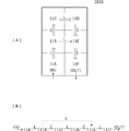
図5(A)、図5(B)は本実施形態の誘電体導波管フィルタ101を構成する4つの共振器の結合構造を示す図である。図5(A)、図5(B)において、共振器11Aは1段目(初段)の共振器であり、共振器11Bは2段目の共振器であり、共振器11Cは3段目の共振器であり、共振器11Dは4段目(終段)の共振器である。図5(A)、図5(B)において二重線で示す経路は主結合路であり、破線は副結合路である。また、図5(A)、図5(B)において“L”は誘導性結合、“C”は容量性結合をそれぞれ表している。
本実施形態の誘電体導波管フィルタ101は、共振器11A,11B,11C,11Dが信号伝搬の主結合路に沿って配置され、主結合部MC12は誘導性結合部であり、主結合部MC23は容量性結合部であり、主結合部MC34は誘導性結合部である。つまり、主結合部は誘導性結合部と容量性結合部とで構成され、誘導性結合部と容量性結合部とが主結合路に沿って交互に繰り返し配置されている。
また、本実施形態の誘電体導波管フィルタ101は、外部との間で信号が入出力される共振器11Aと当該共振器11Aに結合する共振器11Bとの間の主結合部は誘導性結合部である。同様に、外部との間で信号が入出力される共振器11Dと当該共振器11Dに結合する共振器11Cとの間の主結合部は誘導性結合部である。
また、本実施形態の誘電体導波管フィルタ101は、共振器11Aと共振器11Dとは上記主結合路以外に副結合路に沿っても配置されている。つまり、共振器11Aと共振器11Dとの間に副結合部SC14が形成されている。この副結合部SC14は誘導性結合部であり、副結合部SC14の結合は主結合部MC12,MC23,MC34の結合に比べて弱い。ここで、誘導性結合を正の結合係数で表し、容量性結合を負の結合係数で表現する方法もあるので、その表現方法に従えば、「副結合部SC14の結合係数の絶対値は主結合部MC12,MC23,MC34の結合係数の絶対値に比べて小さい。」と言うこともできる。
図6(A)、図6(B)は、誘電体導波管フィルタ101の反射特性と通過特性の周波数特性を示す図である。図6(B)は図6(A)より周波数軸の範囲が広い。
図6(A)、図6(B)において、S11は反射特性、S21は通過特性である。本実施形態の誘電体導波管フィルタ101は、図6(A)に現れているように、3.3GHz~3.4GHzに通過域を有し、3.17GHzに低域側の減衰極を有し、3.48GHzに高域側の減衰極を有する。
このように有極特性が現れる理由は次のとおりである。
まず、共振器の透過位相は、共振器の共振周波数より低周波数側では位相が90°遅れ、共振周波数より高周波数側では位相が90°進む。そして、誘導性結合と容量性結合とでは位相が反転するため、誘導性結合と容量性結合とを組み合わせると、主結合路を伝わる信号と副結合路を伝わる信号とが逆位相かつ同振幅となる周波数が存在する。この周波数に減衰極が現れる。本実施形態の誘電体導波管フィルタ101では、第1共振器11Aと第2共振器11Bとが誘導性結合し、第2共振器11Bと第3共振器11Cとが容量性結合し、第3共振器11Cと第4共振器11Dとが誘導性結合し、第2共振器11Bと第3共振器11Cを飛び越して、第1共振器11Aと第4共振器11Dとが副結合するので(偶数段の飛び越し結合が行われるので)、第1共振器11Aから第4共振器11Dへの主結合路での位相と、第1共振器11Aから第4共振器11Dへの副結合路での位相とは、通過域の低域で反転し、高域でも反転する。つまり通過域の低域と高域の両方に減衰極が現れる。
また、主結合路に沿って容量性結合部が連続していないので、低次モードの励振が生じ難い。そのため、通過域より低周波数帯域に生じるスプリアス応答(図6(B)において楕円で囲む部分は)が非常に小さい。
このように低次のスプリアス応答が抑制される理由は次のとおりである。
図7(A)、図7(B)は、隣接する二つの共振器R1,R2を備える共振系の模式図である。図7(A)はこの共振系の斜視図、図7(B)はその正面図である。図7(B)においては、TE101、TE102、TE103の各モードの電界波を重ねて表している。このように、二つの共振器による共振系において、周波数が低い順にTE101、TE102、TE103・・・、といった伝搬モードTE10に関する共振モードが存在する。このうち、TE101モードは共振器R1と共振器R2とで同相関係にあり、共振モードTE102は共振器R1と共振器R2とで逆相関係にあり、TE103モードは共振器R1と共振器R2とで同相関係にある。ここで、TE101モード(同相)とTE102モード(逆相)との間での結合を誘導性結合とすれば、TE102モード(逆相)とTE103モード(同相)との間での結合は、誘導性結合に対して位相が反転した関係の結合であるので、容量性結合である。
このように、容量性結合は、高次モードであるTE102モードと、高次モードであるTE103モードとの結合であるので、スプリアスとしての低次の共振モードであるTE101モードが通過帯域より低周波数側に現れる。一方、誘導性結合は、基本モードであるTE101モードと、TE102モードとの結合であるので、(それ以上低次のモードは存在しないので、)通過帯域より低周波数側にスプリアスは発生しない。そのため、主結合路に沿って、容量性結合部を誘導性結合部で挟むように配置することで、上記容量性結合を起因とする低次のスプリアス応答が抑制される。
次に、容量性結合の強さの設定構造について示す。図8は、図2(B)に示した非貫通ポスト3を簡素化した非貫通ポストによる容量性結合部の構造を示す透過斜視図である。ここで、誘電体ブロック1の下面からの非貫通ポスト3の突出高さ(深さ)をD、幅をW、厚みをTで表している。ここで、W=6.6mm、T=1.0mmである。また、各共振器の高さHは5,5mm、X方向の幅XWは13mm、Y方向の幅YWは13mmである。
図9は、横軸に非貫通ポスト3の深さをとり、縦軸に共振周波数をとったときの、各共振モードの特性を示す図である。このように、非貫通孔が深くなる程、つまり、容量性結合窓の間隙が狭くなる程、TE101モードの周波数とTE103モードの周波数が下がるが、TE102モードは影響を受けない。各モードの周波数間隔は結合の強さに対応するので、非貫通ポストの深さで結合を調節できる。したがって、容量性結合になるTE102モードとTE103モードの周波数を通過帯域(3.5GHz)近傍の周波数に定めることで、目標仕様のフィルタ特性に適した容量性結合が得られる。
なお、図8では、図2(B)に示した非貫通ポスト3を簡素化した単一の非貫通ポストによる容量性結合部の構造を示したが、図2(B)に示したように、誘電体ブロックの上下面から非貫通ポストを形成する場合にも、同様に、その二つの非貫通ポスト間の間隙Gによって図9に示したものと同様の特性が得られる。
《第2の実施形態》
第2の実施形態では、第1の実施形態で示したものとは共振器の段数等が異なる誘電体導波管フィルタについて示す。
第2の実施形態では、第1の実施形態で示したものとは共振器の段数等が異なる誘電体導波管フィルタについて示す。
図10(A)は第2の実施形態に係る誘電体導波管フィルタ102の外観斜視図であり、図10(B)は誘電体導波管フィルタ102の内部構造を示す透視斜視図である。
この誘電体導波管フィルタ102は直方体状の誘電体ブロック1に構成されている。誘電体ブロック1の底面には入出力用パッド5A,5Bが形成されている。誘電体ブロック1には、入出力用パッド5A,5Bから誘電体ブロック1の内部へ突出する入出力用ポスト4A,4Bが形成されている。また、誘電体ブロック1には、その上面から下面まで貫通する貫通ポスト2A,2B,2C,2D,2E,2Fが形成されている。また、誘電体ブロック1には、その下面から所定深さまで掘られた非貫通ポスト3A,3B,3Cが形成されている。さらに、誘電体ブロック1には、その下面から所定深さまで掘られた共振周波数調整用ポスト6B,6C,6F,6Gが形成されている。
誘電体ブロック1の外面、各貫通ポスト、及び各非貫通ポストに内面には導体膜が形成されている。上記入出力用パッド5A,5Bの周囲はグランド導体として用いる導体膜から分離されている。
図10(B)において二点鎖線は、誘電体ブロック1に構成される共振器の区分を示す仮想上の線である。誘電体導波管フィルタ102は8つの共振器11A~11Hを備える。これら共振器11A~11HはいずれもTE101モードを基本モードとする共振器である。
図1(B)に示した誘電体導波管フィルタ101とは異なり、本実施形態の誘電体導波管フィルタ102では入出力用パッド5A,5Bは円形である。また、貫通ポスト2A,2B,2C,2D,2E,2Fはいずれも横断面長円形の孔であり、所定幅の導体壁を形成する。これら貫通ポスト2A,2B,2C,2D,2E,2Fの形成部は誘導性結合部を構成し、非貫通ポスト3A,3B,3Cの形成部は容量性結合部を構成する。共振周波数調整用ポスト6B,6C,6F,6Gは共振器11B,11C,11F,11Gの共振周波数を微調整するために設けられている。これら共振周波数調整用ポスト6B,6C,6F,6Gの高さ(深さ)を定めることによって共振器11B,11C,11F,11Gの共振周波数をそれぞれ定める。
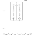
図11(A)、図11(B)は本実施形態の誘電体導波管フィルタ102を構成する8つの共振器の結合構造を示す図である。図11(A)、図11(B)において、共振器11Aは1段目(初段)の共振器であり、共振器11Hは8段目(終段)の共振器である。この共振器11A-11Hの間に2段目から7段目の共振器11B,11C,11D,11E,11F,11Gが順に配置されている。
図11(A)、図11(B)において二重線で示す経路は主結合路であり、破線は副結合路である。また、図11(A)、図11(B)において“L”は誘導性結合、“C”は容量性結合をそれぞれ表している。
本実施形態の誘電体導波管フィルタ102は、共振器11A~11Hが信号伝搬の主結合路に沿って配置されていて、主結合部は誘導性結合部と容量性結合部とで構成され、誘導性結合部と容量性結合部とが主結合路に沿って交互に繰り返し配置されている。
また、本実施形態の誘電体導波管フィルタ102では、外部との間で信号が入出力される共振器11Aと当該共振器11Aに結合する共振器11Bとの間の主結合部は誘導性結合部である。同様に、外部との間で信号が入出力される共振器11Hと当該共振器11Hに結合する共振器11Gとの間の主結合部は誘導性結合部である。
また、本実施形態の誘電体導波管フィルタ102では、共振器11Aと共振器11Dとは、誘導性結合部である副結合部で副結合(飛び越し結合)されている。また、共振器11Cと共振器11Fとは、誘導性結合部である副結合部で副結合(飛び越し結合)されている。さらに、共振器11Eと共振器11Hとは、誘導性結合部である副結合部で副結合(飛び越し結合)されている。各副結合部の結合は主結合部の結合に比べて弱い。
図12は、誘電体導波管フィルタ102の反射特性と通過特性の周波数特性を示す図である。図12において、S11は反射特性、S21は通過特性の特性である。本実施形態の誘電体導波管フィルタ102は、3.4GHz~3.6GHzに通過域を有し、3.34GHz,3.36GHzに低域側の減衰極を有し、3.63GHz,3.66GHzに高域側の減衰極を有する。
共振器11A~11Dは本発明に係る第1共振器から第4共振器にそれぞれ相当する。また、共振器11C~11Fも本発明に係る第1共振器から第4共振器にそれぞれ相当する。さらに、共振器11E~11Hも本発明に係る第1共振器から第4共振器にそれぞれ相当する。
このように、4つの共振器の組が複数組構成されていてもよい。第1の実施形態の誘電体導波管フィルタ101と同様に、本実施形態の誘電体導波管フィルタ102についても、主結合部及び前記副結合部を構成する複数の結合部のうち、容量性結合部の数は誘導性結合部の数より少ない。そのため、容量性結合に起因する低次モードの励振が顕著に現れることなく、通過帯域より低域に現れるスプリアス応答が抑制される。
《第3の実施形態》
第3の実施形態では、第2の実施形態で示した誘電体導波管フィルタとは誘導性結合部及び容量性結合部の構造が異なる誘電体導波管フィルタの幾つかの例について示す。
第3の実施形態では、第2の実施形態で示した誘電体導波管フィルタとは誘導性結合部及び容量性結合部の構造が異なる誘電体導波管フィルタの幾つかの例について示す。
図13(A)は第3の実施形態に係る誘電体導波管フィルタ103Aの外観斜視図であり、図13(B)は誘電体導波管フィルタ103Aの内部構造を示す透視斜視図である。
誘電体導波管フィルタ103Aは直方体状の誘電体ブロック1に構成されている。誘電体ブロック1には、その上面から下面まで貫通する貫通ポスト2AD,2BE,2CFが形成されている。貫通ポスト2ADは図10(B)に示した誘電体導波管フィルタ102が備える貫通ポスト2Aと貫通ポスト2Dとを連結して一体化したものである。また、貫通ポスト2BEは図10(B)に示した誘電体導波管フィルタ102が備える貫通ポスト2Bと貫通ポスト2Eとを連結して一体化したものである。さらに、貫通ポスト2CFは図10(B)に示した誘電体導波管フィルタ102が備える貫通ポスト2Cと貫通ポスト2Fとを連結して一体化したものである。いずれの貫通ポストも平面視でT字状である。その他の各部の構成は第2の実施形態で示した誘電体導波管フィルタ102と同じである。
図13(A)、図13(B)に示したように、主結合部の誘導性結合部と副結合部の誘導性結合部とが一体のポストで構成されていてもよい。
図14(A)は第3の実施形態に係る別の誘電体導波管フィルタ103Bの外観斜視図であり、図14(B)は誘電体導波管フィルタ103Bの内部構造を示す透視斜視図である。
誘電体導波管フィルタ103Bは直方体状の誘電体ブロック1に構成されている。誘電体ブロック1には、その上面から下面まで貫通する貫通ポスト2AD,2BE,2CFが形成されている。図13(B)に示した誘電体導波管フィルタ103Aと同様に、貫通ポスト2ADは図10(B)に示した誘電体導波管フィルタ102が備える貫通ポスト2Aと貫通ポスト2Dとを連結して一体化したものである。また、貫通ポスト2BEは図10(B)に示した誘電体導波管フィルタ102が備える貫通ポスト2Bと貫通ポスト2Eとを連結して一体化したものである。さらに、貫通ポスト2CFは図10(B)に示した誘電体導波管フィルタ102が備える貫通ポスト2Cと貫通ポスト2Fとを連結して一体化したものである。貫通ポスト2AD,2CFは平面視でL字状であり、貫通ポスト2BEは平面視でT字状である。その他の各部の構成は第2の実施形態で示した誘電体導波管フィルタ102と同じである。
図13(A),図13(B)、図14(A)、図14(B)に示したように、誘導性結合部を構成する貫通ポストは、複数の結合部に亘って連続していてもよい。
図15(A)は第3の実施形態に係る更に別の誘電体導波管フィルタ103Cの外観斜視図であり、図15(B)は誘電体導波管フィルタ103Cの内部構造を示す透視斜視図である。
誘電体導波管フィルタ103Cは直方体状の誘電体ブロック1に構成されている。誘電体ブロック1には、その上面から下面まで貫通する貫通ポスト2A,2BE,2CF,2Dが形成されている。また、誘電体ブロック1には、その下面から所定深さまで掘られた非貫通ポスト3A,3B,3Cが形成されている。貫通ポスト2Aと非貫通ポスト3Aとは連結されて一体化されている。また、貫通ポスト2BEと非貫通ポスト3Bは連結されて一体化されている。貫通ポスト2CFは図10(B)に示した誘電体導波管フィルタ102が備える貫通ポスト2Cと貫通ポスト2Fとを連結して一体化したものである。
図15(A)、図15(B)に示したように、誘導性結合部を構成する貫通ポストと容量性結合部を構成する非貫通ポストが連続していてもよい。また、このように、主結合部の容量性結合部と、副結合部の誘導性結合部とが一体のポストで構成されていてもよい。
なお、同様にして、容量性結合の副結合部を備える場合に、主結合部の誘導性結合部と、副結合部の容量性結合部とが一体のポストで構成されていてもよい。また、主結合部の容量性結合部と、副結合部の容量結合部とが一体のポストで構成されていてもよい。
なお、上記説明では、主結合部と副結合部とが一体の共通ポストで構成されることについて述べたが、例えば図15(A)、図15(B)に示したように、主結合部の誘導性結合部と、主結合部の容量性結合部とが一体のポストで構成されていてもよい。同様に、主結合部の容量性結合部と、主結合部の容量性結合部とが一体のポストで構成されていてもよい。
《第4の実施形態》
第4の実施形態では、飛び越し結合部分の構造が、これまでに示したものとは異なる誘電体導波管フィルタの例について示す。
第4の実施形態では、飛び越し結合部分の構造が、これまでに示したものとは異なる誘電体導波管フィルタの例について示す。
図16(A)、図16(B)は第4の実施形態に係る誘電体導波管フィルタ104Aを構成する6つの共振器の結合構造を示す図である。図16(A)、図16(B)において、共振器11Aは1段目(初段)の共振器であり、共振器11Fは6段目(終段)の共振器である。この共振器11A-11Fの間に2段目から5段目の共振器11B,11C,11D,11Eが順に配置されている。
図16(A)、図16(B)において二重線で示す経路は主結合路であり、破線は副結合路である。また、図16(A)、図16(B)において“L”は誘導性結合、“C”は容量性結合をそれぞれ表している。
本実施形態の誘電体導波管フィルタ104Aは、共振器11A~11Fが信号伝搬の主結合路に沿って配置されていて、主結合部は誘導性結合部と容量性結合部とで構成され、誘導性結合部と容量性結合部とが主結合路に沿って交互に繰り返し配置されている。
また、本実施形態の誘電体導波管フィルタ104Aでは、共振器11Bと共振器11Eとは、誘導性結合部である副結合部で副結合(飛び越し結合)されている。これまでに示した各実施形態では、副結合で結合される二つの共振器同士は、主結合路では、誘導性結合⇒容量性結合⇒誘導性結合の順に結合されるが、図16(A)、図16(B)に示す本実施形態の誘電体導波管フィルタ104Aにおいては、副結合で結合される共振器11Bと共振器11Eとは、主結合路では、容量性結合⇒誘導性結合⇒容量性結合の順に結合される。そして、共振器11Bと共振器11Eとは、副結合路では誘導性結合される。
このように、主結合路で容量性結合⇒誘導性結合⇒容量性結合の順に結合される二つの共振器同士を副結合させてもよい。
図17(A)、図17(B)は第4の実施形態に係る別の誘電体導波管フィルタ104Bを構成する6つの共振器の結合構造を示す図である。図17(A)、図17(B)において、共振器11Aは1段目(初段)の共振器であり、共振器11Fは6段目(終段)の共振器である。この共振器11A-11Fの間に2段目から5段目の共振器11B,11C,11D,11Eが順に配置されている。
図17(A)、図17(B)において二重線で示す経路は主結合路である。また、図17(A)、図17(B)において“L”は誘導性結合、“C”は容量性結合をそれぞれ表している。この誘電体導波管フィルタ104Bは副結合路が無い。つまり飛び越し結合が無い。
本実施形態の誘電体導波管フィルタ104Bは、共振器11A-11Fが信号伝搬の主結合路に沿って配置されていて、主結合部は誘導性結合部と容量性結合部とで構成され、誘導性結合部と容量性結合部とが主結合路に沿って交互に繰り返し配置されている。これまでに示した実施形態では、入出力段の共振器と、それに対して主結合する共振器とは誘導性結合するものであったが、この誘電体導波管フィルタ104Bでは、1段目(初段)の共振器11Aと2段目の共振器11Bとは容量性結合していて、6段目(終段)の共振器11Fと5段目の共振器11Eとは容量性結合される。
なお、2段目の共振器11Bと5段目の共振器11Eとは容量性で副結合(飛び越し結合)させない方が好ましい。ここを容量性結合させると、共振器11A→11B→11E→11Fの経路で容量性結合が3段連続するからである。このことを言い換えると、図16(A)、図16(B)に示したように、複数の主結合部のうち、外部との間で信号が入出力される共振器と当該共振器に結合する共振器との間の主結合部が誘導性結合部であることが好ましい。この二つの共振器間(図16(A)、図16(B)に示した例では共振器11Bと共振器11E)を容量性で副結合させても、容量性結合が3段連続することがない。したがって、副結合部を設けることで減衰極を容易に形成できる。
このように、入出力段の共振器と、それに対して主結合する共振器とが容量性結合する構造であってもよい。
《第5の実施形態》
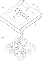
第5の実施形態では、基板に構成された誘電体導波管フィルタの例について示す。図18(A)は第5の実施形態に係る誘電体導波管フィルタ105の外観斜視図であり、図18(B)は誘電体導波管フィルタ105の内部構造を示す透視斜視図である。
第5の実施形態では、基板に構成された誘電体導波管フィルタの例について示す。図18(A)は第5の実施形態に係る誘電体導波管フィルタ105の外観斜視図であり、図18(B)は誘電体導波管フィルタ105の内部構造を示す透視斜視図である。
この誘電体導波管フィルタ105は、直方体状の誘電体ブロックに構成されているのではなく、基板9の一部に構成されている。基板9は、誘電体板(絶縁体板)、その上面に形成された導体膜7、及びその下面に形成された導体膜8を備える。この基板9は例えばガラス・エポキシ(FR-4)基板である。
本実施形態では、図1(A)に示した誘電体ブロック1の外側面に相当する位置に、複数の貫通ポスト(ビア導体)2Vが配列されている。これら貫通ポスト2Vの内面には導体膜が形成されていて、それら導体膜は導体膜7,8に導通している。この構造によって、誘電体ブロック1の外側面と等価的な壁面が構成される。
図18(A)、図18(B)において、貫通ポスト2Vで囲まれる内部の構造は、図1(A)、図1(B)に示したものと同様である。
このようにして、基板集積導波管(SIW:Substrate IntegratedWaveguide)やポスト壁導波管(PWW:Post-Wall Waveguide)で誘電体導波管フィルタを構成してもよい。
等価的な壁面を構成する上記貫通ポスト2Vの隣接間隔は、配列された貫通ポスト2Vの遮断周波数がフィルタの通過帯域よりも高い関係にある。そのためには次に示すように、貫通ポスト2Vの隣接間隔を定めればよい。

ここで、
fc:遮断周波数
a:貫通ポスト2Vの孔-孔間の間隔
b:上下の導体膜7-8間の間隔
Co:真空中の光速
εr:基板の誘電体部(絶縁体部)の比誘電率
m,n:導波管モードの次数
である。
fc:遮断周波数
a:貫通ポスト2Vの孔-孔間の間隔
b:上下の導体膜7-8間の間隔
Co:真空中の光速
εr:基板の誘電体部(絶縁体部)の比誘電率
m,n:導波管モードの次数
である。
上記遮断周波数は電磁波(導波管モード:TEモード)の通りやすさの尺度であり、遮断周波数以下の周波数の電磁波は遮断されて通過しない。配列された貫通ポスト2V同士の間隔から電磁波が漏れると損失が増大するので、貫通ポスト2V同士の間隔を狭くして、遮断周波数をフィルタの通過帯域より高くすることが重要である。
通常、導波管では基本モード(最低次数のTE10モード)を使うので、上式(1)において、m=1、n=0とすることで、次のように簡単に表せる。

さらに、上記で書いたように遮断周波数fcは、すくなくともフィルタの中心周波数f より高くないと損失が増えてしまうので、

の関係となる。例えば、フィルタの中心周波数が高くなると、その分、遮断周波数を高くしなければならず、貫通ポスト2Vの孔-孔間の間隔を狭くする必要がある。
なお、貫通ポスト2Vの内面は導体で埋まった中実構造であってもよい。また、貫通ポスト2Vの断面形状は、円形状でなくてもよく、オーバル形状でも、角丸長方形でもよい。さらに、入出力構造は、基板9の下面や上面に限らず、複数の貫通ポスト2Vによって構成される等価的な側壁に設けられていてもよい。
《第6の実施形態》
第6の実施形態では、誘電体導波管フィルタが適用される携帯電話基地局の例について示す。
第6の実施形態では、誘電体導波管フィルタが適用される携帯電話基地局の例について示す。
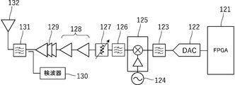
図19は携帯電話基地局のブロック図である。携帯電話基地局の回路には、FPGA121、DAコンバータ122、帯域通過フィルタ123、126,131、シングルミキサー125、局部発振器124、アッテネータ127、アンプ128、パワーアンプ129、検波器130、及びアンテナ132を備える。
上記FPGA121は、変調済みのデジタル信号を発生する。DAコンバータ122は変調済みのデジタル信号をアナログ信号に変換する。帯域通過フィルタ123はベースバンドの周波数帯域の信号を通過させ、それ以外の周波数帯の信号を除去する。シングルミキサー125は、帯域通過フィルタ123の出力信号と局部発振器124の発振信号とを混合してアップコンバートする。帯域通過フィルタ126はアップコンバートにより生じる不要周波数帯を除去する。アッテネータ127は送信波の強度を調整し、アンプ128は送信波を前段増幅する。パワーアンプ129は送信波を電力増幅して、帯域通過フィルタ131を介してアンテナ132から送信波を送信する。帯域通過フィルタ131は送信周波数帯の送信波を通過させる。検波器130は送信電力を検出する。
このような携帯電話基地局において、送信波の周波数帯域を通過させる帯域通過フィルタ126,131に、第1の実施形態から第4の実施形態で示した誘電体導波管フィルタを用いることができる。
最後に、上述の実施形態の説明は、すべての点で例示であって、制限的なものではない。当業者にとって変形及び変更が適宜可能である。本発明の範囲は、上述の実施形態ではなく、特許請求の範囲によって示される。さらに、本発明の範囲には、特許請求の範囲内と均等の範囲内での実施形態からの変更が含まれる。
G…間隙
MC12,MC23,MC34…主結合部
R1,R2…誘電体導波管共振器
SC14…副結合部
1…誘電体ブロック
2A,2B,2C,2D,2E,2F,2G,2J,2K,2V…貫通ポスト
2AD,2BE,2CF…貫通ポスト
3,3A,3B,3C,3L,3U…非貫通ポスト
4A,4B,5A,5B…入出力用パッド
6B,6C,6F,6G…共振周波数調整用ポスト
7,8…導体膜
9…基板
10…グランド導体
11A,11B,11C,11D,11E,11F,11G,11H…誘電体導波管共振器
15A,15B…入出力用ランド
90…回路基板
101,102,103A,103B,103C,104A,104B,105…誘電体導波管フィルタ
121…FPGA
122…DAコンバータ
123,126,131…帯域通過フィルタ
124…局部発振器
125…シングルミキサー
127…アッテネータ
128…アンプ
129…パワーアンプ
130…検波器
132…アンテナ
Claims (11)
- 信号伝搬の主結合路に沿って配置された4以上の複数の誘電体導波管共振器と、
前記複数の誘電体導波管共振器のうち前記主結合路に沿って隣接する誘電体導波管共振器同士の間にそれぞれ設けられた複数の主結合部と、を備え、
前記複数の主結合部は誘導性結合部と容量性結合部とで構成され、前記誘導性結合部と前記容量性結合部とが前記主結合路に沿って交互に繰り返し配置された、
誘電体導波管フィルタ。 - 前記複数の主結合部のうち、外部との間で信号が入出力される誘電体導波管共振器と当該誘電体導波管共振器に結合する誘電体導波管共振器との間の主結合部は誘導性結合部である、
請求項1に記載の誘電体導波管フィルタ。 - 前記複数の誘電体導波管共振器は前記信号伝搬の主結合路以外に副結合路に沿っても配置され、
前記副結合路に沿って隣接する誘電体導波管共振器同士の間に副結合部を更に備える、
請求項1又は2に記載の誘電体導波管フィルタ。 - 前記複数の誘電体導波管共振器のうち前記主結合部で順次結合される4つの誘電体導波管共振器を、順に、第1誘電体導波管共振器、第2誘電体導波管共振器、第3誘電体導波管共振器、及び第4誘電体導波管共振器、で表すとき、前記第1誘電体導波管共振器と前記第2誘電体導波管共振器との間に設けられた主結合部は誘導性結合部であり、前記第2誘電体導波管共振器と前記第3誘電体導波管共振器との間に設けられた主結合部は容量性結合部であり、前記第3誘電体導波管共振器と前記第4誘電体導波管共振器との間に設けられた主結合部は誘導性結合部であり、
前記副結合部のうち、前記第1誘電体導波管共振器と前記第4誘電体導波管共振器との間に設けられた副結合部は誘導性結合部であり、当該副結合部の結合は前記主結合部の結合に比べて弱い、
請求項3に記載の誘電体導波管フィルタ。 - 前記4つの誘電体導波管共振器で構成される組を複数組備え、前記複数組のうち、連続する2組において、前段の組における前記第4誘電体導波管フィルタと後段の組における前記第1誘電体導波管フィルタとの間に前記主結合部が設けられていて、
前記連続する2組において、前段の組における前記第3誘電体導波管フィルタと後段の組における前記第2誘電体導波管フィルタとの間に前記副結合部が設けられている、
請求項4に記載の誘電体導波管フィルタ。 - 前記主結合部の前記誘導性結合部と、前記副結合部の前記誘導性結合部とは、前記誘電体導波管共振器の電界方向に直交する幅を制限する、連続する一体の共通のポストで構成された、
請求項4又は5に記載の誘電体導波管フィルタ。 - 前記主結合部の前記容量性結合部と、前記副結合部の前記容量性結合部とは、前記誘電体導波管共振器の電界方向の幅を制限する、連続する一体の共通のポストで構成された、
請求項4又は5に記載の誘電体導波管フィルタ。 - 前記主結合部の前記容量性結合部と、前記副結合部の前記誘導性結合部とは、前記誘電体導波管共振器の電界方向の幅を制限する部分と、前記誘電体導波管共振器の電界方向に直交する幅を制限する部分と、が連続する一体の共通のポストで構成された、
請求項4又は5に記載の誘電体導波管フィルタ。 - 前記主結合部の前記誘導性結合部と、前記副結合部の前記容量性結合部とは、前記誘電体導波管共振器の電界方向に直交する幅を制限する部分と、前記誘電体導波管共振器の電界方向の幅を制限する部分と、が連続する一体の共通のポストで構成された、
請求項4又は5に記載の誘電体導波管フィルタ。 - 前記ポストは、前記電界方向に視てT字状又はL字状である、
請求項6から9のいずれかに記載の誘電体導波管フィルタ。 - 前記主結合部及び前記副結合部を構成する複数の結合部のうち、容量性結合部の数は誘導性結合部の数より少ない、
請求項3から10のいずれかに記載の誘電体導波管フィルタ。
Priority Applications (3)
| Application Number | Priority Date | Filing Date | Title |
|---|---|---|---|
| CN201980044568.4A CN112385078B (zh) | 2018-07-02 | 2019-05-22 | 电介质波导管滤波器 |
| JP2020528712A JP6927434B2 (ja) | 2018-07-02 | 2019-05-22 | 誘電体導波管フィルタ |
| US17/110,386 US11362406B2 (en) | 2018-07-02 | 2020-12-03 | Dielectric waveguide filter |
Applications Claiming Priority (2)
| Application Number | Priority Date | Filing Date | Title |
|---|---|---|---|
| JP2018125911 | 2018-07-02 | ||
| JP2018-125911 | 2018-07-02 |
Related Child Applications (1)
| Application Number | Title | Priority Date | Filing Date |
|---|---|---|---|
| US17/110,386 Continuation US11362406B2 (en) | 2018-07-02 | 2020-12-03 | Dielectric waveguide filter |
Publications (1)
| Publication Number | Publication Date |
|---|---|
| WO2020008748A1 true WO2020008748A1 (ja) | 2020-01-09 |
Family
ID=69060874
Family Applications (1)
| Application Number | Title | Priority Date | Filing Date |
|---|---|---|---|
| PCT/JP2019/020291 Ceased WO2020008748A1 (ja) | 2018-07-02 | 2019-05-22 | 誘電体導波管フィルタ |
Country Status (4)
| Country | Link |
|---|---|
| US (1) | US11362406B2 (ja) |
| JP (1) | JP6927434B2 (ja) |
| CN (1) | CN112385078B (ja) |
| WO (1) | WO2020008748A1 (ja) |
Cited By (3)
| Publication number | Priority date | Publication date | Assignee | Title |
|---|---|---|---|---|
| TWI748732B (zh) * | 2020-08-20 | 2021-12-01 | 大陸商廈門松元電子有限公司 | 具有電容耦合金屬圖案的混合異波長諧振帶通濾波器 |
| CN115668633A (zh) * | 2020-07-22 | 2023-01-31 | 株式会社村田制作所 | 带通滤波器以及具备该带通滤波器的高频前端电路 |
| WO2025238881A1 (ja) * | 2024-05-15 | 2025-11-20 | 三菱電機株式会社 | 電磁波減衰構造体 |
Families Citing this family (3)
| Publication number | Priority date | Publication date | Assignee | Title |
|---|---|---|---|---|
| EP3972047A4 (en) * | 2019-05-14 | 2022-12-21 | Rosenberger Technologies Co., Ltd. | CROSS-COUPLED FILTER |
| US20230042666A1 (en) * | 2021-08-09 | 2023-02-09 | Meta Platforms, Inc. | Apparatus, system, and method for achieving improved ground station design |
| CN116031602B (zh) * | 2021-10-26 | 2026-06-26 | 深圳三星通信技术研究有限公司 | 一种介质波导谐振器和多模介质波导谐振器 |
Citations (5)
| Publication number | Priority date | Publication date | Assignee | Title |
|---|---|---|---|---|
| JPS50104547A (ja) * | 1974-01-18 | 1975-08-18 | ||
| JPS6324704A (ja) * | 1986-07-17 | 1988-02-02 | Fujitsu Ltd | 帯域通過型濾波器 |
| US20090231064A1 (en) * | 2006-08-04 | 2009-09-17 | Dielectric Laboratories, Inc. | Wideband dielectric waveguide filter |
| WO2016191116A1 (en) * | 2015-05-22 | 2016-12-01 | Cts Corporation | Dielectric waveguide filter with direct coupling and alternative cross-coupling |
| WO2018139321A1 (ja) * | 2017-01-27 | 2018-08-02 | 株式会社村田製作所 | 誘電体導波管フィルタ、高周波フロントエンド回路、および、通信装置 |
Family Cites Families (11)
| Publication number | Priority date | Publication date | Assignee | Title |
|---|---|---|---|---|
| JP2001181029A (ja) * | 1999-10-12 | 2001-07-03 | Murata Mfg Co Ltd | 高周波用誘電体磁器組成物、誘電体共振器、誘電体フィルタ、誘電体デュプレクサおよび通信機装置 |
| US8823470B2 (en) * | 2010-05-17 | 2014-09-02 | Cts Corporation | Dielectric waveguide filter with structure and method for adjusting bandwidth |
| KR20120003354A (ko) * | 2010-07-02 | 2012-01-10 | 한국전자통신연구원 | 이중 모드 공진기 및 삼중 모드 공진기를 포함하는 공진기 필터 및 다이플렉서 |
| JP5688977B2 (ja) * | 2011-01-13 | 2015-03-25 | 東光株式会社 | 誘電体導波管の入出力接続構造 |
| JP5675449B2 (ja) | 2011-03-11 | 2015-02-25 | 東光株式会社 | 誘電体導波管フィルタ |
| US9030279B2 (en) | 2011-05-09 | 2015-05-12 | Cts Corporation | Dielectric waveguide filter with direct coupling and alternative cross-coupling |
| US9130255B2 (en) | 2011-05-09 | 2015-09-08 | Cts Corporation | Dielectric waveguide filter with direct coupling and alternative cross-coupling |
| US9130258B2 (en) * | 2013-09-23 | 2015-09-08 | Cts Corporation | Dielectric waveguide filter with direct coupling and alternative cross-coupling |
| WO2018012294A1 (ja) | 2016-07-13 | 2018-01-18 | 株式会社村田製作所 | 導波管フィルタ回路、導波管フィルタ用実装基板および導波管フィルタ |
| WO2018029956A1 (ja) * | 2016-08-10 | 2018-02-15 | 株式会社村田製作所 | 誘電体導波管フィルタ、高周波フロントエンド回路、Massive MIMOシステム、及び誘電体導波管フィルタの製造方法 |
| CN106960994A (zh) * | 2017-04-25 | 2017-07-18 | 四川省韬光通信有限公司 | 一种便于调节频率与耦合带宽的介质滤波器 |
-
2019
- 2019-05-22 WO PCT/JP2019/020291 patent/WO2020008748A1/ja not_active Ceased
- 2019-05-22 CN CN201980044568.4A patent/CN112385078B/zh active Active
- 2019-05-22 JP JP2020528712A patent/JP6927434B2/ja active Active
-
2020
- 2020-12-03 US US17/110,386 patent/US11362406B2/en active Active
Patent Citations (5)
| Publication number | Priority date | Publication date | Assignee | Title |
|---|---|---|---|---|
| JPS50104547A (ja) * | 1974-01-18 | 1975-08-18 | ||
| JPS6324704A (ja) * | 1986-07-17 | 1988-02-02 | Fujitsu Ltd | 帯域通過型濾波器 |
| US20090231064A1 (en) * | 2006-08-04 | 2009-09-17 | Dielectric Laboratories, Inc. | Wideband dielectric waveguide filter |
| WO2016191116A1 (en) * | 2015-05-22 | 2016-12-01 | Cts Corporation | Dielectric waveguide filter with direct coupling and alternative cross-coupling |
| WO2018139321A1 (ja) * | 2017-01-27 | 2018-08-02 | 株式会社村田製作所 | 誘電体導波管フィルタ、高周波フロントエンド回路、および、通信装置 |
Cited By (4)
| Publication number | Priority date | Publication date | Assignee | Title |
|---|---|---|---|---|
| CN115668633A (zh) * | 2020-07-22 | 2023-01-31 | 株式会社村田制作所 | 带通滤波器以及具备该带通滤波器的高频前端电路 |
| TWI748732B (zh) * | 2020-08-20 | 2021-12-01 | 大陸商廈門松元電子有限公司 | 具有電容耦合金屬圖案的混合異波長諧振帶通濾波器 |
| WO2025238881A1 (ja) * | 2024-05-15 | 2025-11-20 | 三菱電機株式会社 | 電磁波減衰構造体 |
| JPWO2025238881A1 (ja) * | 2024-05-15 | 2025-11-20 |
Also Published As
| Publication number | Publication date |
|---|---|
| CN112385078B (zh) | 2022-03-01 |
| US11362406B2 (en) | 2022-06-14 |
| JPWO2020008748A1 (ja) | 2021-06-24 |
| JP6927434B2 (ja) | 2021-09-01 |
| CN112385078A (zh) | 2021-02-19 |
| US20210091441A1 (en) | 2021-03-25 |
Similar Documents
| Publication | Publication Date | Title |
|---|---|---|
| CN112385078B (zh) | 电介质波导管滤波器 | |
| KR100418607B1 (ko) | 대역필터, 듀플렉서, 고주파 모듈 및 통신장치 | |
| KR100338590B1 (ko) | 유전체 필터, 유전체 듀플렉서 및 통신 장치 | |
| CN115425375B (zh) | 一种带通滤波器及其小型化cq拓扑结构 | |
| JP3498649B2 (ja) | 誘電体フィルタ、デュプレクサおよび通信装置 | |
| WO2022209278A1 (ja) | 誘電体フィルタ | |
| US11742557B2 (en) | Dielectric waveguide filter | |
| US12107312B2 (en) | Band pass filter and high frequency front-end circuit including same | |
| JP4565145B2 (ja) | 超広帯域バンドパスフィルタ | |
| JP2001203503A (ja) | ストリップ線路フィルタ、デュプレクサ、フィルタ装置、通信装置およびストリップ線路フィルタの特性調整方法 | |
| CN1329763A (zh) | 微带滤波器装置 | |
| US20240136995A1 (en) | Filter device and radio frequency front end circuit | |
| KR100449226B1 (ko) | 유전체 듀플렉서 | |
| US12206149B2 (en) | Dielectric waveguide resonator and filter including at least one internal conductor physically isolated from first and second surface conductors and overlapping therewith | |
| KR100369211B1 (ko) | 일체형 유전체 듀플렉서 | |
| KR100524545B1 (ko) | 유전체 필터, 유전체 듀플렉서 및 통신장치 | |
| JP4327876B2 (ja) | 分割給電結合リング共振器対楕円関数フィルタのための装置及び方法 | |
| JP4438253B2 (ja) | バンドパスフィルタの特性調整方法 | |
| JP2000252705A (ja) | 帯域通過フィルタおよびそれを用いたデュプレクサおよびそれらを用いた高周波モジュールおよびそれを用いた通信装置 | |
| KR100363787B1 (ko) | 일체형 유전체 듀플렉서 필터 | |
| SU843039A1 (ru) | Полосовой фильтр на запредельномВОлНОВОдЕ | |
| JP2002325002A (ja) | 高周波用共振部品及びそのスプリアス抑制方法並びにデュプレクサ及び無線通信装置 | |
| KR19990030747A (ko) | 마이크로 스트립 대역 통과 필터 | |
| JP2000077907A (ja) | 誘電体フィルタ | |
| JPH0758521A (ja) | ストリップライン共振器 |
Legal Events
| Date | Code | Title | Description |
|---|---|---|---|
| 121 | Ep: the epo has been informed by wipo that ep was designated in this application |
Ref document number: 19830384 Country of ref document: EP Kind code of ref document: A1 |
|
| ENP | Entry into the national phase |
Ref document number: 2020528712 Country of ref document: JP Kind code of ref document: A |
|
| NENP | Non-entry into the national phase |
Ref country code: DE |
|
| 122 | Ep: pct application non-entry in european phase |
Ref document number: 19830384 Country of ref document: EP Kind code of ref document: A1 |