WO2020008763A1 - Moteur - Google Patents
Moteur Download PDFInfo
- Publication number
- WO2020008763A1 WO2020008763A1 PCT/JP2019/021654 JP2019021654W WO2020008763A1 WO 2020008763 A1 WO2020008763 A1 WO 2020008763A1 JP 2019021654 W JP2019021654 W JP 2019021654W WO 2020008763 A1 WO2020008763 A1 WO 2020008763A1
- Authority
- WO
- WIPO (PCT)
- Prior art keywords
- weight
- commutator
- copper alloy
- carbon brush
- commutator piece
- Prior art date
- Legal status (The legal status is an assumption and is not a legal conclusion. Google has not performed a legal analysis and makes no representation as to the accuracy of the status listed.)
- Ceased
Links
Images


Classifications
-
- C—CHEMISTRY; METALLURGY
- C22—METALLURGY; FERROUS OR NON-FERROUS ALLOYS; TREATMENT OF ALLOYS OR NON-FERROUS METALS
- C22C—ALLOYS
- C22C9/00—Alloys based on copper
-
- H—ELECTRICITY
- H01—ELECTRIC ELEMENTS
- H01B—CABLES; CONDUCTORS; INSULATORS; SELECTION OF MATERIALS FOR THEIR CONDUCTIVE, INSULATING OR DIELECTRIC PROPERTIES
- H01B1/00—Conductors or conductive bodies characterised by the conductive materials; Selection of materials as conductors
- H01B1/02—Conductors or conductive bodies characterised by the conductive materials; Selection of materials as conductors mainly consisting of metals or alloys
-
- H—ELECTRICITY
- H01—ELECTRIC ELEMENTS
- H01R—ELECTRICALLY-CONDUCTIVE CONNECTIONS; STRUCTURAL ASSOCIATIONS OF A PLURALITY OF MUTUALLY-INSULATED ELECTRICAL CONNECTING ELEMENTS; COUPLING DEVICES; CURRENT COLLECTORS
- H01R39/00—Rotary current collectors, distributors or interrupters
- H01R39/02—Details for dynamo electric machines
- H01R39/18—Contacts for co-operation with commutator or slip-ring, e.g. contact brush
- H01R39/20—Contacts for co-operation with commutator or slip-ring, e.g. contact brush characterised by the material thereof
-
- H—ELECTRICITY
- H01—ELECTRIC ELEMENTS
- H01R—ELECTRICALLY-CONDUCTIVE CONNECTIONS; STRUCTURAL ASSOCIATIONS OF A PLURALITY OF MUTUALLY-INSULATED ELECTRICAL CONNECTING ELEMENTS; COUPLING DEVICES; CURRENT COLLECTORS
- H01R39/00—Rotary current collectors, distributors or interrupters
- H01R39/02—Details for dynamo electric machines
- H01R39/18—Contacts for co-operation with commutator or slip-ring, e.g. contact brush
- H01R39/26—Solid sliding contacts, e.g. carbon brush
-
- H—ELECTRICITY
- H02—GENERATION; CONVERSION OR DISTRIBUTION OF ELECTRIC POWER
- H02K—DYNAMO-ELECTRIC MACHINES
- H02K13/00—Structural associations of current collectors with motors or generators, e.g. brush mounting plates or connections to windings; Disposition of current collectors in motors or generators; Arrangements for improving commutation
Definitions
- the present invention relates to a motor including a substantially cylindrical commutator and a carbon brush abutting on an outer peripheral surface of the commutator.
- Patent Document 1 discloses a technique in which iron and phosphorus are used as a copper alloy constituting a commutator in order to improve the wear resistance of the commutator.
- Patent Document 2 discloses a technique in which a copper alloy containing zirconium is used as a copper alloy constituting a commutator in order to improve the wear resistance of the commutator.
- the copper alloy constituting the commutator contains iron or zirconium, the slidability of the commutator is poor, and the surface of the commutator is carbonized by sliding contact with a carbon brush.
- the film is easily formed thick. When the carbon film is formed thick, the contact resistance or the coefficient of friction between the carbon brush and the commutator increases. Thereby, the carbon brush is easily worn. As a result, the life of the motor is shortened.
- the present invention has been made in view of such a point, and an object thereof is to extend the life of a motor.
- One embodiment of the present invention is a motor including a substantially cylindrical commutator and a carbon brush abutting on an outer peripheral surface of the commutator.
- the commutator has a contact area on the outer peripheral surface of the commutator, which is in contact with the carbon brush.
- the commutator has a contact member in a contact region.
- the contact member is made of a copper alloy containing copper.
- the carbon brush contains an abrasive.
- the carbon film is polished and removed by the abrasive contained in the carbon brush. This can suppress an increase in contact resistance or friction coefficient generated between the carbon brush and the commutator due to the thick carbon film. Therefore, the wear of the carbon brush can be suppressed, and the life of the motor can be extended.
- the copper alloy contains iron and phosphorus, and the amount of iron may be set to 0.05% by weight or more, and the amount of phosphorus may be set to 0.015% by weight or more. Thereby, the strength and heat resistance of the contact member are improved, and the wear resistance of the contact member can be improved.
- the amount of iron contained in the copper alloy may be set to 0.15% by weight or less. Thereby, the workability of the contact member can be improved.
- the amount of phosphorus contained in the copper alloy may be set to 0.05% by weight or less. Thereby, the strength of the contact member can be increased.
- the copper alloy contains chromium and zirconium, and the amount of chromium may be set to 0.5% by weight or more, and the amount of zirconium may be set to 0.05% by weight or more.
- the strength and heat resistance of the contact member are improved, and the wear resistance can be improved.
- the amount of chromium contained in the copper alloy may be set to 1.5% by weight or less, and the amount of zirconium may be set to 0.25% by weight or less. Thereby, the workability of the contact member can be improved.
- the copper alloy may further contain silver.
- the amount of silver contained in the copper alloy may be set to 0.03% by weight or less.
- the motor of the present invention even if a carbon film is formed on the surface of the commutator, the carbon film is polished and removed by the abrasive contained in the carbon brush. This can suppress an increase in contact resistance or friction coefficient generated between the carbon brush and the commutator due to the thick carbon film. Therefore, the wear of the carbon brush can be suppressed, and the life of the motor can be extended.
- FIG. 1 is a front view showing a main part of the motor according to the first embodiment of the present invention.
- FIG. 2 is a front view in which a part of a commutator used in the motor according to the first embodiment of the present invention is partially broken.
- FIG. 3 is a partially cutaway front view of a commutator used in a motor according to Embodiment 3 of the present invention.
- FIG. 4 is a front view in which a part of a commutator used in a motor according to a fourth embodiment of the present invention is cut away.
- FIG. 5 is a partially cutaway front view of a commutator used in a motor according to Embodiment 5 of the present invention.
- FIG. 1 is a front view showing a main part of a motor 10 according to the first embodiment of the present invention.
- the motor 10 includes a stator 13, a rotor 23, and a pair of carbon brushes 25 abutting on the outer peripheral surface of the commutator 21.
- the stator 13 includes a field core 11 and a field winding (not shown) wound around the field core 11.
- the rotor 23 includes an armature core 15, an armature winding 17 wound around the armature core 15, a rotating shaft 19, and a substantially cylindrical commutator 21.
- the crossover 17 a is drawn out from the armature winding 17.
- the carbon brush 25 is formed in a rod shape having a rectangular cross section.
- the carbon brush 25 As the carbon brush 25, Cu (copper) is 40 to 50% by weight, C (graphite) is 50 to 60% by weight, and SiO 2 (silicon dioxide) or Al 2 O 3 (aluminum oxide) is 0.2% as an abrasive. Those containing up to 0.6% by weight are used.
- the carbon brush 25 is urged by urging means (not shown) so that one end face thereof is pressed against the outer peripheral surface of the commutator 21.
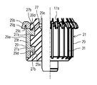
- FIG. 2 is a partially cutaway front view of the commutator 21 used in the motor 10 according to the first embodiment of the present invention.
- the commutator 21 includes a resin cylindrical member 27 formed in a substantially cylindrical shape, and a plurality of commutator pieces disposed on the outer peripheral surface of the cylindrical member 27 at equal intervals in the circumferential direction. 29.
- a slit 31 is formed in a portion of the outer peripheral surface of the commutator 21 where the commutator piece 29 is not provided.
- a pair of concave portions 27a are formed at intervals in the axial direction.
- the axial direction refers to a direction in which the rotating shaft 19 extends.
- Engaging recesses 27b that are recessed in the direction away from each other in the axial direction are formed at the opposite open end of the side surface (the vertical direction in FIG. 2) of each recess 27a.
- the commutator piece 29 includes a long plate-shaped main body portion 29a that extends in the axial direction with its plate surface directed in the radial direction.
- the radial direction is a direction orthogonal to the axial direction and refers to a radial direction about the axis of the rotating shaft 19.
- a hook portion 29b is formed by bending so as to protrude radially outward.
- the hook portion 29b is curved so that a concave portion 29c is formed.
- the concave portion 29c is formed between the outer peripheral surface of the main body portion 29a and the inner peripheral surface of the hook portion 29b.
- a protruding portion 29d is protruded at a position corresponding to the concave portion 27a of the cylindrical member 27 on the inner peripheral surface of the main body portion 29a.
- An engagement protrusion 29e is formed at the tip of each protrusion 29d so as to protrude in a direction away from each other in the axial direction.
- the protruding portion 29d of the commutator piece 29 is embedded in the recess 27a of the tubular member 27 by integral molding, so that the commutator piece 29 is attached to the tubular member 27.
- the copper alloy (first copper alloy) constituting the commutator piece 29 is composed of 0.05 to 0.15% by weight of Fe (iron) and 0.015 to 0.05% of P (phosphorus) throughout. % By weight, containing Cu (copper) and impurities.
- the impurities are components other than iron, phosphorus, silver, chromium, and zirconium (Zr), and refer to components contained in copper without being intentionally added. Copper alloys may not contain impurities.
- a crossover wire 17a drawn out from the armature winding 17 is engaged with the concave portion 29c of the hook portion 29b formed on the commutator piece 29 configured as described above.
- one end surface of the carbon brush 25 is in contact with a longitudinally intermediate portion of the outer peripheral surface of the main body portion 29 a included in the commutator piece 29.
- the carbon brush 25 is electrically connected to the armature winding 17 via the commutator piece 29.
- the commutator piece 29 is a contact member that forms a contact area of the carbon brush 25 on the outer peripheral surface of the commutator 21.
- the reason why the amount of iron contained in the copper alloy constituting the commutator piece 29 is set to 0.05% by weight or more is as follows. That is, when the amount of iron contained in the copper alloy constituting the commutator piece 29 is less than 0.05% by weight, the heat resistance or the wear resistance of the commutator piece 29 cannot be substantially improved.
- the reason why the amount of iron contained in the copper alloy constituting the commutator piece 29 is set to 0.15% by weight or less is as follows. That is, when the amount of iron contained in the copper alloy constituting the commutator piece 29 exceeds 0.15% by weight, the workability of the commutator piece 29 deteriorates.
- the reason why the amount of phosphorus contained in the copper alloy constituting the commutator piece 29 is set to 0.015% by weight or more is as follows. That is, when the amount of phosphorus contained in the copper alloy constituting the commutator piece 29 is less than 0.015% by weight, the heat resistance or the wear resistance of the commutator piece 29 cannot be substantially improved.
- the reason why the amount of phosphorus contained in the copper alloy constituting the commutator piece 29 is set to 0.05% by weight or less is as follows. That is, when the amount of phosphorus contained in the copper alloy constituting the commutator piece 29 exceeds 0.05% by weight, the conductivity of the commutator piece 29 deteriorates.
- the reason why the amount of silver contained in the copper alloy forming the commutator piece 29 is set to 0.03% by weight or less is as follows. That is, when the amount of silver contained in the copper alloy constituting the commutator piece 29 exceeds 0.03% by weight, the conductivity of the commutator piece 29 increases and sparks are easily generated. Therefore, since the surface of the commutator 21 becomes rough due to the spark, the carbon brush 25 is easily worn. Therefore, the life of the motor 10 is shortened.
- the reason why the amount of silicon dioxide or aluminum oxide contained in the carbon brush 25 is set to 0.2 to 0.6% by weight is as follows. That is, when the amount of silicon dioxide or aluminum oxide contained in the copper alloy constituting the commutator piece 29 is less than 0.2% by weight, the carbon film formed on the surface of the commutator piece 29 cannot be sufficiently removed, and If it exceeds 0.6% by weight, the surface of the commutator piece 29 is easily damaged by the sliding contact of the carbon brush 25.
- the carbon film is polished and removed by silicon dioxide or aluminum oxide contained in the carbon brush 25. You. This can suppress an increase in contact resistance or friction coefficient generated between the carbon brush 25 and the commutator piece 29 of the commutator 21 due to the thick carbon film. Therefore, if the motor 10 according to the present embodiment is used, the wear of the carbon brush 25 can be suppressed, and the life of the motor 10 can be extended.
- the amount of iron contained in the copper alloy constituting the commutator segment 29 is set to 0.05% by weight or more, and the amount of phosphorus contained in the copper alloy constituting the commutator segment 29 is 0.015% by weight. Since it is set to be equal to or more than the weight%, the strength and heat resistance of the commutator piece 29 are improved, and the wear resistance of the commutator piece 29 can be improved.
- the amount of iron contained in the copper alloy constituting the commutator piece 29 is set to 0.15% by weight or less, the workability of the commutator piece 29 can be improved.
- the amount of silver contained in the copper alloy constituting the commutator piece 29 is set to 0.03% by weight or less, the conductivity of the commutator piece 29 decreases, and the resistance of the commutator piece 29 decreases. , Sparks are less likely to occur. Therefore, it is possible to suppress the surface of the commutator piece 29 from being roughened due to the spark. If the motor 10 according to the present embodiment is used, therefore, the wear of the carbon brush 25 can be suppressed, and the life of the motor 10 can be extended.
- the motor 10 of the present embodiment includes the substantially cylindrical commutator 21 and the carbon brush 25 abutting on the outer peripheral surface of the commutator 21.
- the commutator 21 has an abutting area on the outer peripheral surface thereof, which abuts on the carbon brush 25.
- the commutator 21 has a commutator piece 29 corresponding to a contact member including a contact region.
- the contact member is made of a copper alloy containing copper.
- the carbon brush 25 contains an abrasive.
- the carbon film is polished and removed by the abrasive contained in the carbon brush. Therefore, it is possible to suppress an increase in contact resistance or friction coefficient generated between the carbon brush and the commutator due to the thick carbon film. Therefore, in the motor according to the present embodiment, the wear of the carbon brush can be suppressed, and the life of the motor can be extended.
- the copper alloy preferably contains 0.05 to 0.15% by weight of iron and 0.015 to 0.05% by weight of phosphorus.
- the copper alloy preferably contains 0.5 to 1.5% by weight of chromium and 0.05 to 0.25% by weight of zirconium.
- the copper alloy preferably contains 0.03% by weight or less of silver.
- the abrasive preferably contains 0.2 to 0.6% by weight of silicon dioxide.
- the abrasive preferably contains 0.2 to 0.6% by weight of aluminum oxide.
- the commutator pieces 29 used in the motor 10 are composed entirely of 0.5 to 1.5% by weight of Cr (chromium) and 0.05 to 0.25% by weight of Zr (zirconium). , Cu (copper) and a copper alloy (second copper alloy) containing impurities.
- the impurities are components other than iron, phosphorus, silver, chromium, and zirconium, and refer to components contained in copper without being intentionally added. Copper alloys may not contain impurities.
- the reason why the amount of chromium contained in the copper alloy constituting the commutator piece 29 is set to 0.5% by weight or more is as follows. That is, if the amount of chromium contained in the copper alloy constituting the commutator piece 29 is less than 0.5% by weight, the wear resistance of the commutator piece 29 can hardly be improved.
- the reason why the amount of chromium contained in the copper alloy forming the commutator piece 29 is set to 1.5% by weight or less is as follows. That is, when the amount of chromium contained in the copper alloy constituting the commutator piece 29 exceeds 1.5% by weight, the workability of the commutator piece 29 deteriorates.
- the reason why the amount of zirconium contained in the copper alloy forming the commutator piece 29 is set to 0.05% by weight or more is as follows. That is, if the amount of zirconium contained in the copper alloy constituting the commutator piece 29 is less than 0.05% by weight, the wear resistance of the commutator piece 29 can hardly be improved.
- the reason why the amount of zirconium contained in the copper alloy constituting the commutator piece 29 is set to 0.25% by weight or less is as follows. That is, when the amount of zirconium contained in the copper alloy constituting the commutator piece 29 exceeds 0.25% by weight, the workability of the commutator piece 29 deteriorates.
- the amount of chromium contained in the copper alloy constituting the commutator piece 29 is set to 0.5% by weight or more, and contained in the copper alloy constituting the commutator piece 29.
- the amount of zirconium is set to 0.05% by weight or more.
- the amount of chromium contained in the copper alloy forming the commutator piece 29 is set to 1.5% by weight or less, and the amount of chromium contained in the copper alloy forming the commutator piece 29 is reduced.
- the amount of zirconium to be used is set to 0.25% by weight or less. Thereby, workability of the commutator piece 29 can be improved.
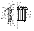
- FIG. 3 is a partially cutaway front view of the commutator 21 used in the motor 10 according to Embodiment 3 of the present invention.
- the commutator piece 29 welds the main body component member 29f forming the main body portion 29a, the protruding portion 29d, and the engagement protruding portion 29e to the hook component member 29g forming the hook portion 29b. It is composed of
- the main body component member 29f is made of a copper alloy common to the commutator piece 29 of the first embodiment, that is, 0.05 to 0.15% by weight of iron, 0.015 to 0.05% by weight of phosphorus, and copper and impurities. Made of a copper alloy.
- the body component member 29f constitutes the contact member.
- the hook member 29g is made of a copper alloy containing 0.03 to 0.08% by weight of Ag (silver), copper, and impurities.
- the impurities are components other than iron, phosphorus, silver, chromium, and zirconium, and refer to components contained in copper without being intentionally added. Copper alloys may not contain impurities.
- the hook part 29b is configured by the hook part constituent member 29g having a lower hardness than the main body part constituent member 29f. Therefore, the bending process becomes easier as compared with the case where the hook portion 29b is made of the same material as the main body component member 29f.
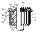
- FIG. 4 is a partially cutaway front view of the commutator 21 used in the motor 10 according to Embodiment 4 of the present invention.
- the commutator piece 29 includes a front member 29h that forms the outer surface of the body 29a and the inner surface of the hook 29b, that is, the surface of the concave portion 29c, and the inner surface of the body 29a. Is welded to the outer surface of the hook portion 29b, that is, the back member 29i that forms the surface on the opposite side of the concave portion 29c.
- the front member 29h is made of a copper alloy common to the commutator piece 29 of the first embodiment, that is, 0.05 to 0.15% by weight of iron, 0.015 to 0.05% by weight of phosphorus, copper made of copper and impurities. It is composed of an alloy.
- the front member 29h constitutes a contact member.
- the back member 29i is made of a copper alloy containing 0.03 to 0.08% by weight of Ag (silver), copper and impurities.
- the impurities are components other than iron, phosphorus, silver, chromium, and zirconium, and refer to components contained in copper without being intentionally added. Copper alloys may not contain impurities.
- the hook portion 29b is configured by two layers of the front member 29h and the back member 29i having a lower hardness than the front member 29h. Therefore, the bending process is easier than when the entire hook portion 29b is formed of the same material as the front side member 29h.
- FIG. 5 is a front view in which a part of a commutator 21 used in a motor 10 according to a fifth embodiment of the present invention is cut away.
- the hook portion 29b of the commutator piece 29 of the fourth embodiment is constituted only by the back member 29i.
- the hook portion 29b includes only the back member 29i having a lower hardness than the front member 29h. Therefore, the bending process becomes easier as compared with the case where the hook portion 29b is made of the same material as the front side member 29h.
- the operating voltage of the motor 10 was 13 V
- the operating current of the motor 10 was 10 to 40 A
- the temperature of the carbon brush 25 was 100 to 130 ° C. in a test environment of 20 to 30 ° C.
- the rotor was rotated at 1000 to 5000 rpm (revolutions per minute) for 250 hours.
- the life of the carbon brush 25 was calculated based on the length of the carbon brush 25 after the test.
- the entire commutator piece 29 was made of a copper alloy (TAMAC4 manufactured by Mitsubishi Shindoh Co., Ltd.) composed of 0.1% by weight of iron, 0.03% by weight of phosphorus, and copper and impurities.
- the carbon brush 25 used was one containing 45% by weight of copper, 52.7% by weight of graphite, and 2.3% by weight of silicon dioxide as an abrasive. The life of the carbon brush 25 calculated by this test was 798 hours.
- the entire commutator piece 29 is composed of 0.5 to 1.5% by weight of chromium, 0.05 to 0.25% by weight of zirconium, and a copper alloy (UNS (Unified Numbering System) number) manufactured by Mitsubishi Materials Corporation. No. C18150).
- the carbon brush 25 used was one containing 45% by weight of copper, 52.7% by weight of graphite, and 2.3% by weight of silicon dioxide as an abrasive. The life of the carbon brush 25 calculated by this test was 821 hours.
- the entire commutator piece 29 was made of a copper alloy (TAMAC4 manufactured by Mitsubishi Shindoh Co., Ltd.) composed of 0.1% by weight of iron, 0.03% by weight of phosphorus, and copper and impurities.
- the carbon brush 25 used was one containing 45% by weight of copper and 55% by weight of graphite. The life of the carbon brush 25 calculated by this test was 375 hours.
- the entire commutator piece 29 is made of 0.5 to 1.5% by weight of chromium, 0.05 to 0.25% by weight of zirconium, and a copper alloy (UNS No. C18150 manufactured by Mitsubishi Materials Corporation) composed of copper and impurities. Configured.
- the carbon brush 25 used was one containing 45% by weight of copper and 55% by weight of graphite. The life of the carbon brush 25 calculated by this test was 316 hours.
- the entire commutator piece 29 was composed of a copper alloy (CMB4 specified by JIS C2801 manufactured by Mitsubishi Materials Corporation) composed of 0.06 to 0.10% by weight of silver, copper and impurities.
- the carbon brush 25 used was one containing 45% by weight of copper, 52.7% by weight of graphite, and 2.3% by weight of silicon dioxide as an abrasive. The life of the carbon brush 25 calculated by this test was 552 hours.
- the entire commutator piece 29 was composed of a copper alloy (CMB4 specified by JIS C2801 manufactured by Mitsubishi Materials Corporation) composed of 0.06 to 0.10% by weight of silver, copper and impurities.
- the carbon brush 25 used was one containing 45% by weight of copper and 55% by weight of graphite. The life of the carbon brush 25 calculated by this test was 565 hours.
- the calculated life of the carbon brush 25 was longer in Examples 1 and 2 than in Comparative Examples 1 to 4.
- the results of Examples 1 and 2 (evaluation of ⁇ in Table 1) can obtain a brush life more than twice as long as the results of Comparative Examples 1 and 2 (evaluation of ⁇ in Table 1). I confirmed that I could do it.
- the results of Examples 1 and 2 (evaluation of ⁇ in Table 1) can obtain a brush life about 1.5 times that of the results of Comparative Examples 3 and 4 (evaluation of ⁇ in Table 1). I confirmed that.
- the silver contained in the copper alloy constituting the contact member is 0% by weight, but may be contained as long as it is 0.03% by weight or less.
- the silver content is 0.01% by weight or less, sparks generated between the commutator 21 and the carbon brush 25 are further less likely to occur. Accordingly, it is possible to suppress the surface of the commutator 21 from being roughened due to the spark.
- the abrasive contained in the carbon brush 25 is silicon dioxide or aluminum oxide, but may be WC (tungsten carbide) or SiC (silicon carbide).
- the front member 29h is made of the same copper alloy as the commutator piece 29 of the first embodiment, but may be made of the same copper alloy as the commutator piece 29 of the second embodiment.
- the front side member 29h may be made of a common copper alloy with the commutator piece 29 of the second embodiment.
- the motor according to the present invention can extend the life of the motor. INDUSTRIAL APPLICABILITY
- the motor according to the present invention is useful when applied to household or industrial electric equipment such as a vacuum cleaner, a vehicle, or the like.
Landscapes
- Engineering & Computer Science (AREA)
- Chemical & Material Sciences (AREA)
- Power Engineering (AREA)
- Materials Engineering (AREA)
- Mechanical Engineering (AREA)
- Metallurgy (AREA)
- Organic Chemistry (AREA)
- Motor Or Generator Current Collectors (AREA)
- Conductive Materials (AREA)
Abstract
La présente invention concerne un moteur pourvu d'un commutateur sensiblement cylindrique et d'une brosse en carbone qui vient en contact avec la surface circonférentielle externe du commutateur. Le commutateur comprend un élément de contact formé à partir d'un alliage de cuivre comprenant du cuivre, dans une région de contact de la surface circonférentielle externe où le commutateur entre en contact avec la brosse en carbone. La brosse en carbone comprend un matériau de polissage.
Applications Claiming Priority (2)
| Application Number | Priority Date | Filing Date | Title |
|---|---|---|---|
| JP2018-128776 | 2018-07-06 | ||
| JP2018128776A JP2021158702A (ja) | 2018-07-06 | 2018-07-06 | モータ |
Publications (1)
| Publication Number | Publication Date |
|---|---|
| WO2020008763A1 true WO2020008763A1 (fr) | 2020-01-09 |
Family
ID=69059541
Family Applications (1)
| Application Number | Title | Priority Date | Filing Date |
|---|---|---|---|
| PCT/JP2019/021654 Ceased WO2020008763A1 (fr) | 2018-07-06 | 2019-05-31 | Moteur |
Country Status (2)
| Country | Link |
|---|---|
| JP (1) | JP2021158702A (fr) |
| WO (1) | WO2020008763A1 (fr) |
Families Citing this family (1)
| Publication number | Priority date | Publication date | Assignee | Title |
|---|---|---|---|---|
| JP2024003444A (ja) * | 2022-06-27 | 2024-01-15 | マブチモーター株式会社 | 接点構造及びブラシモータ |
Citations (3)
| Publication number | Priority date | Publication date | Assignee | Title |
|---|---|---|---|---|
| JPH09111372A (ja) * | 1995-10-12 | 1997-04-28 | Mitsuba Corp | 燃料給送ポンプに使用されるモータの整流子用銅合金 |
| JPH09263864A (ja) * | 1996-03-26 | 1997-10-07 | Kobe Steel Ltd | 耐放電摩耗性が優れる銅合金 |
| US20030155837A1 (en) * | 2000-06-28 | 2003-08-21 | Kazuhiro Takahashi | Carbon brush for electric machine |
-
2018
- 2018-07-06 JP JP2018128776A patent/JP2021158702A/ja active Pending
-
2019
- 2019-05-31 WO PCT/JP2019/021654 patent/WO2020008763A1/fr not_active Ceased
Patent Citations (3)
| Publication number | Priority date | Publication date | Assignee | Title |
|---|---|---|---|---|
| JPH09111372A (ja) * | 1995-10-12 | 1997-04-28 | Mitsuba Corp | 燃料給送ポンプに使用されるモータの整流子用銅合金 |
| JPH09263864A (ja) * | 1996-03-26 | 1997-10-07 | Kobe Steel Ltd | 耐放電摩耗性が優れる銅合金 |
| US20030155837A1 (en) * | 2000-06-28 | 2003-08-21 | Kazuhiro Takahashi | Carbon brush for electric machine |
Also Published As
| Publication number | Publication date |
|---|---|
| JP2021158702A (ja) | 2021-10-07 |
Similar Documents
| Publication | Publication Date | Title |
|---|---|---|
| JP5977387B2 (ja) | 減速機構及び減速機構付きモータ | |
| JP2021158702A (ja) | モータ | |
| US20060226730A1 (en) | Brush assembly for dynamoelectric machines having increased wear life | |
| JP4802558B2 (ja) | 積層樹脂ブラシ | |
| JP6753757B2 (ja) | 燃料ポンプ用dcモータ | |
| JP2011501648A (ja) | 電気機械のためのばねを有したブラシ装置 | |
| JPWO2008093393A1 (ja) | 電動機、電動送風機並びに電気掃除機 | |
| CN218678749U (zh) | 用于电机的换向器、用于电机的电刷和电机 | |
| JP2011250516A (ja) | ブラシ装置及びモータ | |
| JP6138119B2 (ja) | 直流モータ | |
| JP6473890B2 (ja) | 整流子およびそれを備えた整流子電動機 | |
| WO2012029207A1 (fr) | Moteur à collecteur | |
| JP7499468B2 (ja) | 電動機及び電気機器 | |
| JP6344413B2 (ja) | 整流子電動機 | |
| JPH04121039A (ja) | 整流子電動機の整流子 | |
| JP2019122179A (ja) | ブラシ付き電動機 | |
| CN107147250B (zh) | 换向器电动机、电动鼓风机、吸尘器 | |
| JP2015220925A (ja) | 摺動接点機構、電動機及び発電機 | |
| JP2008029129A (ja) | 直流モータ | |
| JP2014007858A (ja) | 直流モータ | |
| JP2016152666A5 (fr) | ||
| JP2015220924A (ja) | 摺動接点機構、電動機及び発電機 | |
| JPH10210715A (ja) | 整流子電動機 | |
| JPH07336953A (ja) | 電気掃除機用整流子モータ | |
| WO2023135955A1 (fr) | Moteur électrique et dispositif électrique |
Legal Events
| Date | Code | Title | Description |
|---|---|---|---|
| 121 | Ep: the epo has been informed by wipo that ep was designated in this application |
Ref document number: 19831560 Country of ref document: EP Kind code of ref document: A1 |
|
| NENP | Non-entry into the national phase |
Ref country code: DE |
|
| 122 | Ep: pct application non-entry in european phase |
Ref document number: 19831560 Country of ref document: EP Kind code of ref document: A1 |
|
| NENP | Non-entry into the national phase |
Ref country code: JP |