WO2020008763A1 - モータ - Google Patents
モータ Download PDFInfo
- Publication number
- WO2020008763A1 WO2020008763A1 PCT/JP2019/021654 JP2019021654W WO2020008763A1 WO 2020008763 A1 WO2020008763 A1 WO 2020008763A1 JP 2019021654 W JP2019021654 W JP 2019021654W WO 2020008763 A1 WO2020008763 A1 WO 2020008763A1
- Authority
- WO
- WIPO (PCT)
- Prior art keywords
- weight
- commutator
- copper alloy
- carbon brush
- commutator piece
- Prior art date
- Legal status (The legal status is an assumption and is not a legal conclusion. Google has not performed a legal analysis and makes no representation as to the accuracy of the status listed.)
- Ceased
Links
Images


Classifications
-
- C—CHEMISTRY; METALLURGY
- C22—METALLURGY; FERROUS OR NON-FERROUS ALLOYS; TREATMENT OF ALLOYS OR NON-FERROUS METALS
- C22C—ALLOYS
- C22C9/00—Alloys based on copper
-
- H—ELECTRICITY
- H01—ELECTRIC ELEMENTS
- H01B—CABLES; CONDUCTORS; INSULATORS; SELECTION OF MATERIALS FOR THEIR CONDUCTIVE, INSULATING OR DIELECTRIC PROPERTIES
- H01B1/00—Conductors or conductive bodies characterised by the conductive materials; Selection of materials as conductors
- H01B1/02—Conductors or conductive bodies characterised by the conductive materials; Selection of materials as conductors mainly consisting of metals or alloys
-
- H—ELECTRICITY
- H01—ELECTRIC ELEMENTS
- H01R—ELECTRICALLY-CONDUCTIVE CONNECTIONS; STRUCTURAL ASSOCIATIONS OF A PLURALITY OF MUTUALLY-INSULATED ELECTRICAL CONNECTING ELEMENTS; COUPLING DEVICES; CURRENT COLLECTORS
- H01R39/00—Rotary current collectors, distributors or interrupters
- H01R39/02—Details for dynamo electric machines
- H01R39/18—Contacts for co-operation with commutator or slip-ring, e.g. contact brush
- H01R39/20—Contacts for co-operation with commutator or slip-ring, e.g. contact brush characterised by the material thereof
-
- H—ELECTRICITY
- H01—ELECTRIC ELEMENTS
- H01R—ELECTRICALLY-CONDUCTIVE CONNECTIONS; STRUCTURAL ASSOCIATIONS OF A PLURALITY OF MUTUALLY-INSULATED ELECTRICAL CONNECTING ELEMENTS; COUPLING DEVICES; CURRENT COLLECTORS
- H01R39/00—Rotary current collectors, distributors or interrupters
- H01R39/02—Details for dynamo electric machines
- H01R39/18—Contacts for co-operation with commutator or slip-ring, e.g. contact brush
- H01R39/26—Solid sliding contacts, e.g. carbon brush
-
- H—ELECTRICITY
- H02—GENERATION; CONVERSION OR DISTRIBUTION OF ELECTRIC POWER
- H02K—DYNAMO-ELECTRIC MACHINES
- H02K13/00—Structural associations of current collectors with motors or generators, e.g. brush mounting plates or connections to windings; Disposition of current collectors in motors or generators; Arrangements for improving commutation
Definitions
- the present invention relates to a motor including a substantially cylindrical commutator and a carbon brush abutting on an outer peripheral surface of the commutator.
- Patent Document 1 discloses a technique in which iron and phosphorus are used as a copper alloy constituting a commutator in order to improve the wear resistance of the commutator.
- Patent Document 2 discloses a technique in which a copper alloy containing zirconium is used as a copper alloy constituting a commutator in order to improve the wear resistance of the commutator.
- the copper alloy constituting the commutator contains iron or zirconium, the slidability of the commutator is poor, and the surface of the commutator is carbonized by sliding contact with a carbon brush.
- the film is easily formed thick. When the carbon film is formed thick, the contact resistance or the coefficient of friction between the carbon brush and the commutator increases. Thereby, the carbon brush is easily worn. As a result, the life of the motor is shortened.
- the present invention has been made in view of such a point, and an object thereof is to extend the life of a motor.
- One embodiment of the present invention is a motor including a substantially cylindrical commutator and a carbon brush abutting on an outer peripheral surface of the commutator.
- the commutator has a contact area on the outer peripheral surface of the commutator, which is in contact with the carbon brush.
- the commutator has a contact member in a contact region.
- the contact member is made of a copper alloy containing copper.
- the carbon brush contains an abrasive.
- the carbon film is polished and removed by the abrasive contained in the carbon brush. This can suppress an increase in contact resistance or friction coefficient generated between the carbon brush and the commutator due to the thick carbon film. Therefore, the wear of the carbon brush can be suppressed, and the life of the motor can be extended.
- the copper alloy contains iron and phosphorus, and the amount of iron may be set to 0.05% by weight or more, and the amount of phosphorus may be set to 0.015% by weight or more. Thereby, the strength and heat resistance of the contact member are improved, and the wear resistance of the contact member can be improved.
- the amount of iron contained in the copper alloy may be set to 0.15% by weight or less. Thereby, the workability of the contact member can be improved.
- the amount of phosphorus contained in the copper alloy may be set to 0.05% by weight or less. Thereby, the strength of the contact member can be increased.
- the copper alloy contains chromium and zirconium, and the amount of chromium may be set to 0.5% by weight or more, and the amount of zirconium may be set to 0.05% by weight or more.
- the strength and heat resistance of the contact member are improved, and the wear resistance can be improved.
- the amount of chromium contained in the copper alloy may be set to 1.5% by weight or less, and the amount of zirconium may be set to 0.25% by weight or less. Thereby, the workability of the contact member can be improved.
- the copper alloy may further contain silver.
- the amount of silver contained in the copper alloy may be set to 0.03% by weight or less.
- the motor of the present invention even if a carbon film is formed on the surface of the commutator, the carbon film is polished and removed by the abrasive contained in the carbon brush. This can suppress an increase in contact resistance or friction coefficient generated between the carbon brush and the commutator due to the thick carbon film. Therefore, the wear of the carbon brush can be suppressed, and the life of the motor can be extended.
- FIG. 1 is a front view showing a main part of the motor according to the first embodiment of the present invention.
- FIG. 2 is a front view in which a part of a commutator used in the motor according to the first embodiment of the present invention is partially broken.
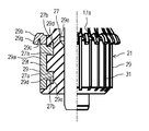
- FIG. 3 is a partially cutaway front view of a commutator used in a motor according to Embodiment 3 of the present invention.
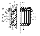
- FIG. 4 is a front view in which a part of a commutator used in a motor according to a fourth embodiment of the present invention is cut away.
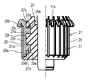
- FIG. 5 is a partially cutaway front view of a commutator used in a motor according to Embodiment 5 of the present invention.
- FIG. 1 is a front view showing a main part of a motor 10 according to the first embodiment of the present invention.
- the motor 10 includes a stator 13, a rotor 23, and a pair of carbon brushes 25 abutting on the outer peripheral surface of the commutator 21.
- the stator 13 includes a field core 11 and a field winding (not shown) wound around the field core 11.
- the rotor 23 includes an armature core 15, an armature winding 17 wound around the armature core 15, a rotating shaft 19, and a substantially cylindrical commutator 21.
- the crossover 17 a is drawn out from the armature winding 17.
- the carbon brush 25 is formed in a rod shape having a rectangular cross section.
- the carbon brush 25 As the carbon brush 25, Cu (copper) is 40 to 50% by weight, C (graphite) is 50 to 60% by weight, and SiO 2 (silicon dioxide) or Al 2 O 3 (aluminum oxide) is 0.2% as an abrasive. Those containing up to 0.6% by weight are used.
- the carbon brush 25 is urged by urging means (not shown) so that one end face thereof is pressed against the outer peripheral surface of the commutator 21.
- FIG. 2 is a partially cutaway front view of the commutator 21 used in the motor 10 according to the first embodiment of the present invention.
- the commutator 21 includes a resin cylindrical member 27 formed in a substantially cylindrical shape, and a plurality of commutator pieces disposed on the outer peripheral surface of the cylindrical member 27 at equal intervals in the circumferential direction. 29.
- a slit 31 is formed in a portion of the outer peripheral surface of the commutator 21 where the commutator piece 29 is not provided.
- a pair of concave portions 27a are formed at intervals in the axial direction.
- the axial direction refers to a direction in which the rotating shaft 19 extends.
- Engaging recesses 27b that are recessed in the direction away from each other in the axial direction are formed at the opposite open end of the side surface (the vertical direction in FIG. 2) of each recess 27a.
- the commutator piece 29 includes a long plate-shaped main body portion 29a that extends in the axial direction with its plate surface directed in the radial direction.
- the radial direction is a direction orthogonal to the axial direction and refers to a radial direction about the axis of the rotating shaft 19.
- a hook portion 29b is formed by bending so as to protrude radially outward.
- the hook portion 29b is curved so that a concave portion 29c is formed.
- the concave portion 29c is formed between the outer peripheral surface of the main body portion 29a and the inner peripheral surface of the hook portion 29b.
- a protruding portion 29d is protruded at a position corresponding to the concave portion 27a of the cylindrical member 27 on the inner peripheral surface of the main body portion 29a.
- An engagement protrusion 29e is formed at the tip of each protrusion 29d so as to protrude in a direction away from each other in the axial direction.
- the protruding portion 29d of the commutator piece 29 is embedded in the recess 27a of the tubular member 27 by integral molding, so that the commutator piece 29 is attached to the tubular member 27.
- the copper alloy (first copper alloy) constituting the commutator piece 29 is composed of 0.05 to 0.15% by weight of Fe (iron) and 0.015 to 0.05% of P (phosphorus) throughout. % By weight, containing Cu (copper) and impurities.
- the impurities are components other than iron, phosphorus, silver, chromium, and zirconium (Zr), and refer to components contained in copper without being intentionally added. Copper alloys may not contain impurities.
- a crossover wire 17a drawn out from the armature winding 17 is engaged with the concave portion 29c of the hook portion 29b formed on the commutator piece 29 configured as described above.
- one end surface of the carbon brush 25 is in contact with a longitudinally intermediate portion of the outer peripheral surface of the main body portion 29 a included in the commutator piece 29.
- the carbon brush 25 is electrically connected to the armature winding 17 via the commutator piece 29.
- the commutator piece 29 is a contact member that forms a contact area of the carbon brush 25 on the outer peripheral surface of the commutator 21.
- the reason why the amount of iron contained in the copper alloy constituting the commutator piece 29 is set to 0.05% by weight or more is as follows. That is, when the amount of iron contained in the copper alloy constituting the commutator piece 29 is less than 0.05% by weight, the heat resistance or the wear resistance of the commutator piece 29 cannot be substantially improved.
- the reason why the amount of iron contained in the copper alloy constituting the commutator piece 29 is set to 0.15% by weight or less is as follows. That is, when the amount of iron contained in the copper alloy constituting the commutator piece 29 exceeds 0.15% by weight, the workability of the commutator piece 29 deteriorates.
- the reason why the amount of phosphorus contained in the copper alloy constituting the commutator piece 29 is set to 0.015% by weight or more is as follows. That is, when the amount of phosphorus contained in the copper alloy constituting the commutator piece 29 is less than 0.015% by weight, the heat resistance or the wear resistance of the commutator piece 29 cannot be substantially improved.
- the reason why the amount of phosphorus contained in the copper alloy constituting the commutator piece 29 is set to 0.05% by weight or less is as follows. That is, when the amount of phosphorus contained in the copper alloy constituting the commutator piece 29 exceeds 0.05% by weight, the conductivity of the commutator piece 29 deteriorates.
- the reason why the amount of silver contained in the copper alloy forming the commutator piece 29 is set to 0.03% by weight or less is as follows. That is, when the amount of silver contained in the copper alloy constituting the commutator piece 29 exceeds 0.03% by weight, the conductivity of the commutator piece 29 increases and sparks are easily generated. Therefore, since the surface of the commutator 21 becomes rough due to the spark, the carbon brush 25 is easily worn. Therefore, the life of the motor 10 is shortened.
- the reason why the amount of silicon dioxide or aluminum oxide contained in the carbon brush 25 is set to 0.2 to 0.6% by weight is as follows. That is, when the amount of silicon dioxide or aluminum oxide contained in the copper alloy constituting the commutator piece 29 is less than 0.2% by weight, the carbon film formed on the surface of the commutator piece 29 cannot be sufficiently removed, and If it exceeds 0.6% by weight, the surface of the commutator piece 29 is easily damaged by the sliding contact of the carbon brush 25.
- the carbon film is polished and removed by silicon dioxide or aluminum oxide contained in the carbon brush 25. You. This can suppress an increase in contact resistance or friction coefficient generated between the carbon brush 25 and the commutator piece 29 of the commutator 21 due to the thick carbon film. Therefore, if the motor 10 according to the present embodiment is used, the wear of the carbon brush 25 can be suppressed, and the life of the motor 10 can be extended.
- the amount of iron contained in the copper alloy constituting the commutator segment 29 is set to 0.05% by weight or more, and the amount of phosphorus contained in the copper alloy constituting the commutator segment 29 is 0.015% by weight. Since it is set to be equal to or more than the weight%, the strength and heat resistance of the commutator piece 29 are improved, and the wear resistance of the commutator piece 29 can be improved.
- the amount of iron contained in the copper alloy constituting the commutator piece 29 is set to 0.15% by weight or less, the workability of the commutator piece 29 can be improved.
- the amount of silver contained in the copper alloy constituting the commutator piece 29 is set to 0.03% by weight or less, the conductivity of the commutator piece 29 decreases, and the resistance of the commutator piece 29 decreases. , Sparks are less likely to occur. Therefore, it is possible to suppress the surface of the commutator piece 29 from being roughened due to the spark. If the motor 10 according to the present embodiment is used, therefore, the wear of the carbon brush 25 can be suppressed, and the life of the motor 10 can be extended.
- the motor 10 of the present embodiment includes the substantially cylindrical commutator 21 and the carbon brush 25 abutting on the outer peripheral surface of the commutator 21.
- the commutator 21 has an abutting area on the outer peripheral surface thereof, which abuts on the carbon brush 25.
- the commutator 21 has a commutator piece 29 corresponding to a contact member including a contact region.
- the contact member is made of a copper alloy containing copper.
- the carbon brush 25 contains an abrasive.
- the carbon film is polished and removed by the abrasive contained in the carbon brush. Therefore, it is possible to suppress an increase in contact resistance or friction coefficient generated between the carbon brush and the commutator due to the thick carbon film. Therefore, in the motor according to the present embodiment, the wear of the carbon brush can be suppressed, and the life of the motor can be extended.
- the copper alloy preferably contains 0.05 to 0.15% by weight of iron and 0.015 to 0.05% by weight of phosphorus.
- the copper alloy preferably contains 0.5 to 1.5% by weight of chromium and 0.05 to 0.25% by weight of zirconium.
- the copper alloy preferably contains 0.03% by weight or less of silver.
- the abrasive preferably contains 0.2 to 0.6% by weight of silicon dioxide.
- the abrasive preferably contains 0.2 to 0.6% by weight of aluminum oxide.
- the commutator pieces 29 used in the motor 10 are composed entirely of 0.5 to 1.5% by weight of Cr (chromium) and 0.05 to 0.25% by weight of Zr (zirconium). , Cu (copper) and a copper alloy (second copper alloy) containing impurities.
- the impurities are components other than iron, phosphorus, silver, chromium, and zirconium, and refer to components contained in copper without being intentionally added. Copper alloys may not contain impurities.
- the reason why the amount of chromium contained in the copper alloy constituting the commutator piece 29 is set to 0.5% by weight or more is as follows. That is, if the amount of chromium contained in the copper alloy constituting the commutator piece 29 is less than 0.5% by weight, the wear resistance of the commutator piece 29 can hardly be improved.
- the reason why the amount of chromium contained in the copper alloy forming the commutator piece 29 is set to 1.5% by weight or less is as follows. That is, when the amount of chromium contained in the copper alloy constituting the commutator piece 29 exceeds 1.5% by weight, the workability of the commutator piece 29 deteriorates.
- the reason why the amount of zirconium contained in the copper alloy forming the commutator piece 29 is set to 0.05% by weight or more is as follows. That is, if the amount of zirconium contained in the copper alloy constituting the commutator piece 29 is less than 0.05% by weight, the wear resistance of the commutator piece 29 can hardly be improved.
- the reason why the amount of zirconium contained in the copper alloy constituting the commutator piece 29 is set to 0.25% by weight or less is as follows. That is, when the amount of zirconium contained in the copper alloy constituting the commutator piece 29 exceeds 0.25% by weight, the workability of the commutator piece 29 deteriorates.
- the amount of chromium contained in the copper alloy constituting the commutator piece 29 is set to 0.5% by weight or more, and contained in the copper alloy constituting the commutator piece 29.
- the amount of zirconium is set to 0.05% by weight or more.
- the amount of chromium contained in the copper alloy forming the commutator piece 29 is set to 1.5% by weight or less, and the amount of chromium contained in the copper alloy forming the commutator piece 29 is reduced.
- the amount of zirconium to be used is set to 0.25% by weight or less. Thereby, workability of the commutator piece 29 can be improved.
- FIG. 3 is a partially cutaway front view of the commutator 21 used in the motor 10 according to Embodiment 3 of the present invention.
- the commutator piece 29 welds the main body component member 29f forming the main body portion 29a, the protruding portion 29d, and the engagement protruding portion 29e to the hook component member 29g forming the hook portion 29b. It is composed of
- the main body component member 29f is made of a copper alloy common to the commutator piece 29 of the first embodiment, that is, 0.05 to 0.15% by weight of iron, 0.015 to 0.05% by weight of phosphorus, and copper and impurities. Made of a copper alloy.
- the body component member 29f constitutes the contact member.
- the hook member 29g is made of a copper alloy containing 0.03 to 0.08% by weight of Ag (silver), copper, and impurities.
- the impurities are components other than iron, phosphorus, silver, chromium, and zirconium, and refer to components contained in copper without being intentionally added. Copper alloys may not contain impurities.
- the hook part 29b is configured by the hook part constituent member 29g having a lower hardness than the main body part constituent member 29f. Therefore, the bending process becomes easier as compared with the case where the hook portion 29b is made of the same material as the main body component member 29f.
- FIG. 4 is a partially cutaway front view of the commutator 21 used in the motor 10 according to Embodiment 4 of the present invention.
- the commutator piece 29 includes a front member 29h that forms the outer surface of the body 29a and the inner surface of the hook 29b, that is, the surface of the concave portion 29c, and the inner surface of the body 29a. Is welded to the outer surface of the hook portion 29b, that is, the back member 29i that forms the surface on the opposite side of the concave portion 29c.
- the front member 29h is made of a copper alloy common to the commutator piece 29 of the first embodiment, that is, 0.05 to 0.15% by weight of iron, 0.015 to 0.05% by weight of phosphorus, copper made of copper and impurities. It is composed of an alloy.
- the front member 29h constitutes a contact member.
- the back member 29i is made of a copper alloy containing 0.03 to 0.08% by weight of Ag (silver), copper and impurities.
- the impurities are components other than iron, phosphorus, silver, chromium, and zirconium, and refer to components contained in copper without being intentionally added. Copper alloys may not contain impurities.
- the hook portion 29b is configured by two layers of the front member 29h and the back member 29i having a lower hardness than the front member 29h. Therefore, the bending process is easier than when the entire hook portion 29b is formed of the same material as the front side member 29h.
- FIG. 5 is a front view in which a part of a commutator 21 used in a motor 10 according to a fifth embodiment of the present invention is cut away.
- the hook portion 29b of the commutator piece 29 of the fourth embodiment is constituted only by the back member 29i.
- the hook portion 29b includes only the back member 29i having a lower hardness than the front member 29h. Therefore, the bending process becomes easier as compared with the case where the hook portion 29b is made of the same material as the front side member 29h.
- the operating voltage of the motor 10 was 13 V
- the operating current of the motor 10 was 10 to 40 A
- the temperature of the carbon brush 25 was 100 to 130 ° C. in a test environment of 20 to 30 ° C.
- the rotor was rotated at 1000 to 5000 rpm (revolutions per minute) for 250 hours.
- the life of the carbon brush 25 was calculated based on the length of the carbon brush 25 after the test.
- the entire commutator piece 29 was made of a copper alloy (TAMAC4 manufactured by Mitsubishi Shindoh Co., Ltd.) composed of 0.1% by weight of iron, 0.03% by weight of phosphorus, and copper and impurities.
- the carbon brush 25 used was one containing 45% by weight of copper, 52.7% by weight of graphite, and 2.3% by weight of silicon dioxide as an abrasive. The life of the carbon brush 25 calculated by this test was 798 hours.
- the entire commutator piece 29 is composed of 0.5 to 1.5% by weight of chromium, 0.05 to 0.25% by weight of zirconium, and a copper alloy (UNS (Unified Numbering System) number) manufactured by Mitsubishi Materials Corporation. No. C18150).
- the carbon brush 25 used was one containing 45% by weight of copper, 52.7% by weight of graphite, and 2.3% by weight of silicon dioxide as an abrasive. The life of the carbon brush 25 calculated by this test was 821 hours.
- the entire commutator piece 29 was made of a copper alloy (TAMAC4 manufactured by Mitsubishi Shindoh Co., Ltd.) composed of 0.1% by weight of iron, 0.03% by weight of phosphorus, and copper and impurities.
- the carbon brush 25 used was one containing 45% by weight of copper and 55% by weight of graphite. The life of the carbon brush 25 calculated by this test was 375 hours.
- the entire commutator piece 29 is made of 0.5 to 1.5% by weight of chromium, 0.05 to 0.25% by weight of zirconium, and a copper alloy (UNS No. C18150 manufactured by Mitsubishi Materials Corporation) composed of copper and impurities. Configured.
- the carbon brush 25 used was one containing 45% by weight of copper and 55% by weight of graphite. The life of the carbon brush 25 calculated by this test was 316 hours.
- the entire commutator piece 29 was composed of a copper alloy (CMB4 specified by JIS C2801 manufactured by Mitsubishi Materials Corporation) composed of 0.06 to 0.10% by weight of silver, copper and impurities.
- the carbon brush 25 used was one containing 45% by weight of copper, 52.7% by weight of graphite, and 2.3% by weight of silicon dioxide as an abrasive. The life of the carbon brush 25 calculated by this test was 552 hours.
- the entire commutator piece 29 was composed of a copper alloy (CMB4 specified by JIS C2801 manufactured by Mitsubishi Materials Corporation) composed of 0.06 to 0.10% by weight of silver, copper and impurities.
- the carbon brush 25 used was one containing 45% by weight of copper and 55% by weight of graphite. The life of the carbon brush 25 calculated by this test was 565 hours.
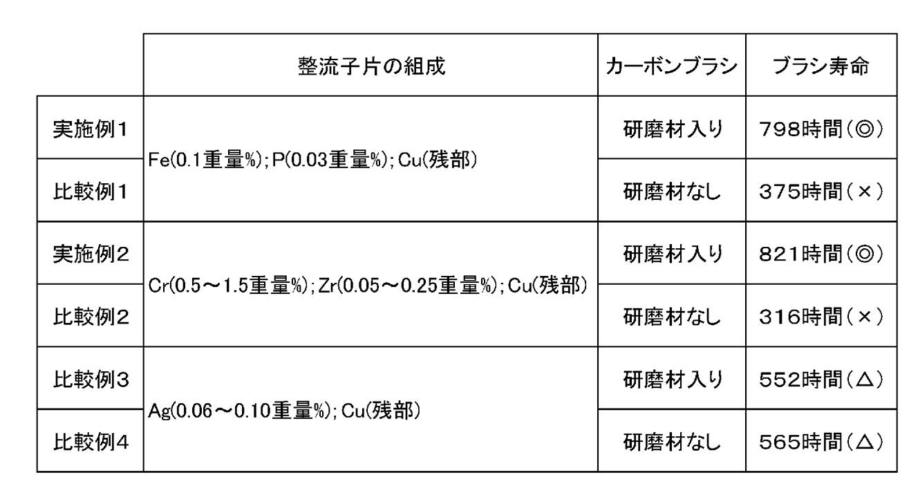
- the calculated life of the carbon brush 25 was longer in Examples 1 and 2 than in Comparative Examples 1 to 4.
- the results of Examples 1 and 2 (evaluation of ⁇ in Table 1) can obtain a brush life more than twice as long as the results of Comparative Examples 1 and 2 (evaluation of ⁇ in Table 1). I confirmed that I could do it.
- the results of Examples 1 and 2 (evaluation of ⁇ in Table 1) can obtain a brush life about 1.5 times that of the results of Comparative Examples 3 and 4 (evaluation of ⁇ in Table 1). I confirmed that.
- the silver contained in the copper alloy constituting the contact member is 0% by weight, but may be contained as long as it is 0.03% by weight or less.
- the silver content is 0.01% by weight or less, sparks generated between the commutator 21 and the carbon brush 25 are further less likely to occur. Accordingly, it is possible to suppress the surface of the commutator 21 from being roughened due to the spark.
- the abrasive contained in the carbon brush 25 is silicon dioxide or aluminum oxide, but may be WC (tungsten carbide) or SiC (silicon carbide).
- the front member 29h is made of the same copper alloy as the commutator piece 29 of the first embodiment, but may be made of the same copper alloy as the commutator piece 29 of the second embodiment.
- the front side member 29h may be made of a common copper alloy with the commutator piece 29 of the second embodiment.
- the motor according to the present invention can extend the life of the motor. INDUSTRIAL APPLICABILITY
- the motor according to the present invention is useful when applied to household or industrial electric equipment such as a vacuum cleaner, a vehicle, or the like.
Landscapes
- Engineering & Computer Science (AREA)
- Chemical & Material Sciences (AREA)
- Power Engineering (AREA)
- Materials Engineering (AREA)
- Mechanical Engineering (AREA)
- Metallurgy (AREA)
- Organic Chemistry (AREA)
- Motor Or Generator Current Collectors (AREA)
- Conductive Materials (AREA)
Abstract
モータは、実質的に筒状の整流子と、整流子の外周面に当接するカーボンブラシと、を備える。整流子は、カーボンブラシと当接する外周面の当接領域に、銅を含む銅合金で構成された当接部材を有する。カーボンブラシは、研磨材を含む。
Description
本発明は、実質的に筒状の整流子と、当該整流子の外周面に当接するカーボンブラシとを備えたモータに関する。
特許文献1には、整流子の耐摩耗性を改善するために、整流子を構成する銅合金として、鉄及びリンを含有したものを採用する技術が開示されている。
特許文献2には、整流子の耐摩耗性を改善するために、整流子を構成する銅合金として、ジルコニウムを含有したものを採用する技術が開示されている。しかし、特許文献1,2では、整流子を構成する銅合金が、鉄又はジルコニウムを含有しているので、整流子の摺動性が悪く、カーボンブラシとの摺接により整流子の表面にカーボン皮膜が厚く形成されやすい。カーボン皮膜が厚く形成されると、カーボンブラシと整流子との間の接触抵抗又は摩擦係数が増大する。これにより、カーボンブラシが摩耗しやすくなる。その結果、モータの寿命が短くなる。
本発明は、かかる点に鑑みてなされたものであり、その目的は、モータの寿命を長くすることである。
本発明の一態様は、実質的に筒状の整流子と、整流子の外周面に当接するカーボンブラシと、を備えたモータである。整流子は、整流子の外周面に、カーボンブラシと当接する当接領域を有する。整流子は、当接領域に当接部材を有する。当接部材は、銅を含む銅合金で構成される。カーボンブラシは、研磨材を含む。
この態様によると、整流子の表面にカーボン皮膜が形成されても、カーボンブラシに含有される研磨材によりカーボン皮膜が研磨されて除去される。これにより、厚いカーボン皮膜に起因してカーボンブラシと整流子との間に生じる接触抵抗又は摩擦係数が増大するのを抑制できる。したがって、カーボンブラシの摩耗を抑制でき、モータの寿命を長くできる。
また、銅合金は鉄とリンを含有し、鉄の量が0.05重量%以上に設定され、かつリンの量が0.015重量%以上に設定されてもよい。これにより、当接部材の強度及び耐熱性が向上し、当接部材の耐摩耗性を改善できる。
また、銅合金に含有される鉄の量が0.15重量%以下に設定されてもよい。これにより、当接部材の加工性を良好にできる。
また、銅合金に含有されるリンの量が0.05重量%以下に設定されてもよい。これにより、当接部材の強度を高められる。
一方、銅合金はクロムとジルコニウムを含有し、クロムの量が0.5重量%以上に設定され、かつジルコニウムの量が0.05重量%以上に設定されてもよい。これにより、当接部材の強度及び耐熱性が向上し、耐摩耗性を改善できる。
また、銅合金に含有されるクロムの量が1.5重量%以下に設定され、かつジルコニウムの量が0.25重量%以下に設定されてもよい。これにより、当接部材の加工性を良好にできる。
また、銅合金はさらに銀を含有してもよい。この場合、銅合金に含まれる銀の量が0.03重量%以下に設定されていればよい。これにより、当接部材の導電性が低くなり、当接部材の抵抗によって、スパークが発生しにくくなる。よって、スパークに起因して当接部材の表面が粗くなることを抑制できる。したがって、カーボンブラシの摩耗を抑制でき、モータの寿命を長くできる。
本発明にかかるモータによれば、整流子の表面にカーボン皮膜が形成されても、カーボン皮膜がカーボンブラシに含有される研磨材により研磨されて除去される。これにより、厚いカーボン皮膜に起因してカーボンブラシと整流子との間に生じる接触抵抗又は摩擦係数が増大するのを抑制できる。したがって、カーボンブラシの摩耗を抑制でき、モータの寿命を長くできる。
以下、本発明の実施形態について図面に基づいて説明する。以下の好ましい実施形態の説明は、本質的に例示に過ぎず、本発明、その適用物或いはその用途を制限することを意図するものでは全くない。
(実施形態1)
図1は、本発明の実施形態1に係るモータ10の要部を示す正面図である。図1に示すように、モータ10は、ステータ13、ロータ23と、整流子21の外周面に当接する1対のカーボンブラシ25と、を備えている。ステータ13は、界磁コア11と、界磁コア11に巻装された界磁巻線(図示せず)とで構成される。ロータ23は、電機子コア15と、電機子コア15に巻装された電機子巻線17と、回転軸19と、実質的に筒状の整流子21と、を有する。渡り線17aは、電機子巻線17から引き出されている。カーボンブラシ25は、断面矩形状で延びる棒状に形成されている。カーボンブラシ25としては、Cu(銅)を40~50重量%、C(黒鉛)を50~60重量%、研磨材としてSiO2(二酸化ケイ素)又はAl2O3(酸化アルミニウム)を0.2~0.6重量%含有したものが用いられる。カーボンブラシ25は、図示しない付勢手段により、その一端面が整流子21の外周面に押し付けられるように付勢されている。
図1は、本発明の実施形態1に係るモータ10の要部を示す正面図である。図1に示すように、モータ10は、ステータ13、ロータ23と、整流子21の外周面に当接する1対のカーボンブラシ25と、を備えている。ステータ13は、界磁コア11と、界磁コア11に巻装された界磁巻線(図示せず)とで構成される。ロータ23は、電機子コア15と、電機子コア15に巻装された電機子巻線17と、回転軸19と、実質的に筒状の整流子21と、を有する。渡り線17aは、電機子巻線17から引き出されている。カーボンブラシ25は、断面矩形状で延びる棒状に形成されている。カーボンブラシ25としては、Cu(銅)を40~50重量%、C(黒鉛)を50~60重量%、研磨材としてSiO2(二酸化ケイ素)又はAl2O3(酸化アルミニウム)を0.2~0.6重量%含有したものが用いられる。カーボンブラシ25は、図示しない付勢手段により、その一端面が整流子21の外周面に押し付けられるように付勢されている。
図2は、本発明の実施形態1に係るモータ10に用いられる整流子21の一部を破断した正面図である。整流子21は、実質的に筒状に形成された樹脂製の筒部材27と、筒部材27の外周面において、周方向に向かって互いに等しい間隔を空けて配設された複数の整流子片29と、を有している。整流子21の外周面における整流子片29を配設しない箇所には、スリット31が形成されている。筒部材27の外周面における整流子片29を配設した領域には、1対の凹陥部27aが軸方向に互いに間隔を空けて形成されている。ここで軸方向とは、回転軸19が延伸する方向をいう。各凹陥部27aの側面(図2中、上下方向)の反開放側端部には、軸方向に互いに離れる方向に凹む係合凹部27bが形成されている。
一方、整流子片29は、その板面を径方向に向けて軸方向に延びる長板状の本体部29aを備える。ここで径方向とは、軸方向と直交する方向であって、回転軸19の軸心を中心とする半径方向をいう。本体部29aの長手方向一端部には、フック部29bが径方向外側に張り出すように曲げ加工により形成されている。フック部29bは、凹状部29cが形成されるように湾曲している。具体的に、凹状部29cは、本体部29aの外周面とフック部29bの内周面との間で形成される。また、本体部29aの内周側の面における筒部材27の凹陥部27aに対応する箇所には、突出部29dが突設されている。各突出部29dの先端部には、軸方向において互いに離れる方向に向かって突出する係合突部29eが形成されている。整流子片29の突出部29dが一体成形により筒部材27の凹陥部27aに埋め込まれることで、整流子片29が筒部材27に取り付けられている。この状態で、整流子片29の係合突部29eが筒部材27の係合凹部27bに係合することで、突出部29dの凹陥部27aからの抜けが規制されている。整流子片29を構成する銅合金(第1の銅合金)は、全体に亘って、Fe(鉄)を0.05~0.15重量%、P(リン)を0.015~0.05重量%、Cu(銅)及び不純物を含有する。不純物とは、鉄、リン、銀、クロム及びジルコニウム(Zr)以外の成分であって、意図的に添加せずに銅に含まれる成分をいう。銅合金は不純物を含有しない場合もある。
上記のように構成された整流子片29に形成されたフック部29bの凹状部29cには、電機子巻線17から引き出された渡り線17aが係合している。一方、整流子片29に含まれる本体部29aの外周側の面の長手方向中途部には、カーボンブラシ25の一端面が当接している。これによって、カーボンブラシ25が整流子片29を介して電機子巻線17に電気的に接続される。整流子21が軸周り、すなわち回転軸19の周方向に回転すると、カーボンブラシ25の一端面が整流子片29に摺接する。したがって、整流子片29が、整流子21の外周面におけるカーボンブラシ25の当接領域を構成する当接部材となっている。
ここで、整流子片29を構成する銅合金に含有される鉄の量を0.05重量%以上に設定したのは、つぎの理由による。すなわち、整流子片29を構成する銅合金に含有される鉄の量が0.05重量%未満では、整流子片29の耐熱性又は耐摩耗性を殆ど改善できないからである。
また、整流子片29を構成する銅合金に含有される鉄の量を0.15重量%以下に設定したのは、つぎの理由による。すなわち、整流子片29を構成する銅合金に含有される鉄の量が0.15重量%を超えると、整流子片29の加工性が悪化するからである。
また、整流子片29を構成する銅合金に含有されるリンの量を0.015重量%以上に設定したのは、つぎの理由による。すなわち、整流子片29を構成する銅合金に含有されるリンの量が0.015重量%未満では、整流子片29の耐熱性又は耐摩耗性を殆ど改善できないからである。
また、整流子片29を構成する銅合金に含有されるリンの量を0.05重量%以下に設定したのは、つぎの理由による。すなわち、整流子片29を構成する銅合金に含有されるリンの量が0.05重量%を超えると、整流子片29の導電性が悪化するからである。
また、整流子片29を構成する銅合金に含有される銀の量を0.03重量%以下に設定したのは、つぎの理由による。すなわち、整流子片29を構成する銅合金に含有される銀の量が0.03重量%を超えると、整流子片29の導電性が高くなってスパークが発生しやすくなる。よって、スパークに起因して整流子21の表面が粗くなるため、カーボンブラシ25が摩耗しやすくなる。したがって、モータ10の寿命が短くなる。
また、カーボンブラシ25に含有される二酸化ケイ素又は酸化アルミニウムの量を0.2~0.6重量%に設定したのは、つぎの理由による。すなわち、整流子片29を構成する銅合金に含有される二酸化ケイ素又は酸化アルミニウムの量が0.2重量%未満では、整流子片29の表面に形成されるカーボン皮膜を十分除去できず、0.6重量%を超えると、カーボンブラシ25の摺接により整流子片29の表面に傷がつきやすくなるからである。
したがって、実施形態1によれば、整流子21が有する整流子片29の表面にカーボン皮膜が形成されても、カーボンブラシ25に含有される二酸化ケイ素又は酸化アルミニウムによりカーボン皮膜が研磨されて除去される。これにより、厚いカーボン皮膜に起因してカーボンブラシ25と整流子21が有する整流子片29との間に生じる接触抵抗又は摩擦係数が増大するのを抑制できる。したがって、本実施形態に係るモータ10を用いれば、カーボンブラシ25の摩耗を抑制でき、モータ10の寿命を長くできる。
また、整流子片29を構成する銅合金に含有される鉄の量が0.05重量%以上に設定され、かつ整流子片29を構成する銅合金に含有されるリンの量が0.015重量%以上に設定されているので、整流子片29の強度及び耐熱性が向上し、整流子片29の耐摩耗性を改善できる。
また、整流子片29を構成する銅合金に含有される鉄の量が0.15重量%以下に設定されているので、整流子片29の加工性を良好にできる。
また、整流子片29を構成する銅合金に含有されるリンの量が0.05重量%以下に設定されているので、整流子片29の強度を高められる。
また、整流子片29を構成する銅合金に含有される銀の量が0.03重量%以下に設定されているので、整流子片29の導電性が低くなり、整流子片29の抵抗によって、スパークが発生しにくくなる。よって、スパークに起因して整流子片29の表面が粗くなることを抑制できる。本実施形態に係るモータ10を用いれば、したがって、カーボンブラシ25の摩耗を抑制でき、モータ10の寿命を長くできる。
また、カーボンブラシ25に含有される二酸化ケイ素又は酸化アルミニウムの量が0.2重量%以上に設定されているので、整流子片29の表面に形成されるカーボン皮膜を十分除去できる。カーボンブラシ25に含有される二酸化ケイ素又は酸化アルミニウムの量が0.6重量%以下に設定されているので、整流子片29の表面に傷がつきにくい。
以上のように、本実施形態のモータ10は、実質的に筒状の整流子21と、整流子21の外周面に当接するカーボンブラシ25と、を備える。整流子21の外周面に、カーボンブラシ25と当接する当接領域を有する。整流子21は、当接領域を含む当接部材に相当する整流子片29を有する。当接部材は、銅を含む銅合金で構成される。カーボンブラシ25は、研磨材を含む。
これにより、整流子の表面にカーボン皮膜が形成されても、カーボンブラシに含有される研磨材によりカーボン皮膜が研磨されて除去される。よって、厚いカーボン皮膜に起因してカーボンブラシと整流子との間に生じる接触抵抗又は摩擦係数が増大することを抑制できる。したがって、本実施形態に係るモータは、カーボンブラシの摩耗を抑制でき、モータの寿命を長くできる。
また、銅合金は、鉄を0.05~0.15重量%、リンを0.015~0.05重量%含有することが好ましい。
また、銅合金は、クロムを0.5~1.5重量%、ジルコニウムを0.05~0.25重量%含有することが好ましい。
また、銅合金は、0.03重量%以下の銀を含有することが好ましい。
また、研磨材は、二酸化ケイ素を0.2~0.6重量%含有することが好ましい。
また、研磨材は、酸化アルミニウムを0.2~0.6重量%含有することが好ましい。
(実施形態2)
実施形態2では、モータ10に用いられる整流子片29が、全体に亘って、Cr(クロム)を0.5~1.5重量%、Zr(ジルコニウム)を0.05~0.25重量%、Cu(銅)及び不純物を含有する銅合金(第2の銅合金)で構成されている。不純物とは、鉄、リン、銀、クロム及びジルコニウム以外の成分であって、意図的に添加せずに銅に含まれる成分をいう。銅合金は不純物を含有しない場合もある。
実施形態2では、モータ10に用いられる整流子片29が、全体に亘って、Cr(クロム)を0.5~1.5重量%、Zr(ジルコニウム)を0.05~0.25重量%、Cu(銅)及び不純物を含有する銅合金(第2の銅合金)で構成されている。不純物とは、鉄、リン、銀、クロム及びジルコニウム以外の成分であって、意図的に添加せずに銅に含まれる成分をいう。銅合金は不純物を含有しない場合もある。
ここで、整流子片29を構成する銅合金に含有されるクロムの量を0.5重量%以上に設定したのは、つぎの理由による。すなわち、整流子片29を構成する銅合金に含有されるクロムの量が0.5重量%未満では、整流子片29の耐摩耗性を殆ど改善できないからである。
また、整流子片29を構成する銅合金に含有されるクロムの量を1.5重量%以下に設定したのは、つぎの理由による。すなわち、整流子片29を構成する銅合金に含有されるクロムの量が1.5重量%を超えると、整流子片29の加工性が悪化するからである。
また、整流子片29を構成する銅合金に含有されるジルコニウムの量を0.05重量%以上に設定したのは、つぎの理由による。すなわち、整流子片29を構成する銅合金に含有されるジルコニウムの量が0.05重量%未満では、整流子片29の耐摩耗性を殆ど改善できないからである。
また、整流子片29を構成する銅合金に含有されるジルコニウムの量を0.25重量%以下に設定したのは、つぎの理由による。すなわち、整流子片29を構成する銅合金に含有されるジルコニウムの量が0.25重量%を超えると、整流子片29の加工性が悪化するからである。
その他の構成は、実施形態1と同じであるので、その詳細な説明を援用する。
したがって、実施形態2によれば、整流子片29を構成する銅合金に含有されるクロムの量が0.5重量%以上に設定され、かつ整流子片29を構成する銅合金に含有されるジルコニウムの量が0.05重量%以上に設定されている。これにより、整流子片29の強度及び耐熱性が向上し、整流子片29の耐摩耗性を改善できる。
また、本実施形態に係るモータ10は、整流子片29を構成する銅合金に含有されるクロムの量が1.5重量%以下に設定され、かつ整流子片29を構成する銅合金に含有されるジルコニウムの量が0.25重量%以下に設定されている。これにより、整流子片29の加工性を良好にできる。
(実施形態3)
図3は、本発明の実施形態3に係るモータ10に用いられる整流子21の一部を破断した正面図である。実施形態3では、整流子片29が、本体部29a、突出部29d、及び係合突部29eを構成する本体部構成部材29fと、フック部29bを構成するフック部構成部材29gとを互いに溶接することで構成されている。本体部構成部材29fは、実施形態1の整流子片29と共通の銅合金、すなわち鉄を0.05~0.15重量%、リンを0.015~0.05重量%、銅及び不純物からなる銅合金で構成されている。本体部構成部材29fが当接部材を構成している。フック部構成部材29gは、Ag(銀)を0.03~0.08重量%、銅及び不純物からなる銅合金で構成している。不純物とは、鉄、リン、銀、クロム及びジルコニウム以外の成分であって、意図的に添加せずに銅に含まれる成分をいう。銅合金は不純物を含有しない場合もある。
図3は、本発明の実施形態3に係るモータ10に用いられる整流子21の一部を破断した正面図である。実施形態3では、整流子片29が、本体部29a、突出部29d、及び係合突部29eを構成する本体部構成部材29fと、フック部29bを構成するフック部構成部材29gとを互いに溶接することで構成されている。本体部構成部材29fは、実施形態1の整流子片29と共通の銅合金、すなわち鉄を0.05~0.15重量%、リンを0.015~0.05重量%、銅及び不純物からなる銅合金で構成されている。本体部構成部材29fが当接部材を構成している。フック部構成部材29gは、Ag(銀)を0.03~0.08重量%、銅及び不純物からなる銅合金で構成している。不純物とは、鉄、リン、銀、クロム及びジルコニウム以外の成分であって、意図的に添加せずに銅に含まれる成分をいう。銅合金は不純物を含有しない場合もある。
その他の構成は、実施形態1と同じであるので、同一の構成箇所には同一の符号を付してその詳細な説明を援用する。
実施形態3によれば、本実施形態に係るモータ10は、フック部29bを本体部構成部材29fよりも硬度の低いフック部構成部材29gで構成した。よって、フック部29bを本体部構成部材29fと共通の材質で構成した場合に比べ、曲げ加工が容易になる。
(実施形態4)
図4は、本発明の実施形態4に係るモータ10に用いられる整流子21の一部を破断した正面図である。実施形態4では、整流子片29が、本体部29aの外周側の面及びフック部29bの内周側、すなわち凹状部29c側の面を構成する表側部材29hと、本体部29aの内周側の面及びフック部29bの外周側、すなわち凹状部29cの反対側の面を構成する裏側部材29iとを互いに溶接することで構成されている。表側部材29hは、実施形態1の整流子片29と共通の銅合金、すなわち鉄を0.05~0.15重量%、リンを0.015~0.05重量%、銅及び不純物からなる銅合金で構成されている。表側部材29hが当接部材を構成している。裏側部材29iは、Ag(銀)を0.03~0.08重量%、銅及び不純物からなる銅合金で構成されている。不純物とは、鉄、リン、銀、クロム及びジルコニウム以外の成分であって、意図的に添加せずに銅に含まれる成分をいう。銅合金は不純物を含有しない場合もある。
図4は、本発明の実施形態4に係るモータ10に用いられる整流子21の一部を破断した正面図である。実施形態4では、整流子片29が、本体部29aの外周側の面及びフック部29bの内周側、すなわち凹状部29c側の面を構成する表側部材29hと、本体部29aの内周側の面及びフック部29bの外周側、すなわち凹状部29cの反対側の面を構成する裏側部材29iとを互いに溶接することで構成されている。表側部材29hは、実施形態1の整流子片29と共通の銅合金、すなわち鉄を0.05~0.15重量%、リンを0.015~0.05重量%、銅及び不純物からなる銅合金で構成されている。表側部材29hが当接部材を構成している。裏側部材29iは、Ag(銀)を0.03~0.08重量%、銅及び不純物からなる銅合金で構成されている。不純物とは、鉄、リン、銀、クロム及びジルコニウム以外の成分であって、意図的に添加せずに銅に含まれる成分をいう。銅合金は不純物を含有しない場合もある。
その他の構成は、実施形態1と同じであるので、同一の構成箇所には同一の符号を付してその詳細な説明を援用する。
したがって、実施形態4によれば、本実施形態に係るモータ10は、フック部29bを表側部材29hと表側部材29hよりも硬度の低い裏側部材29iとの2層で構成した。よって、フック部29b全体を表側部材29hと共通の材質で構成した場合に比べ、曲げ加工が容易になる。
(実施形態5)
図5は、本発明の実施形態5に係るモータ10に用いられる整流子21の一部を破断した正面図である。実施形態5では、実施形態4の整流子片29のフック部29bが裏側部材29iだけで構成されている。
図5は、本発明の実施形態5に係るモータ10に用いられる整流子21の一部を破断した正面図である。実施形態5では、実施形態4の整流子片29のフック部29bが裏側部材29iだけで構成されている。
その他の構成は、実施形態4と同じであるので、同一の構成箇所には同一の符号を付してその詳細な説明を援用する。
したがって、実施形態5によれば、本実施形態に係るモータ10は、フック部29bを表側部材29hよりも硬度の低い裏側部材29iだけで構成した。よって、フック部29bを表側部材29hと共通の材質で構成した場合に比べ、曲げ加工が容易になる。
以下、本発明の実施例1,2及び比較例1~4について説明する。
実施例1,2及び比較例1~4では、20~30℃の試験環境で、モータ10の作動電圧を13V、モータ10の作動電流を10~40A、カーボンブラシ25の温度を100~130℃に設定して、ロータを1000~5000rpm(revolutions per minute)で250時間回転させる試験を行った。試験後のカーボンブラシ25の長さに基づいてカーボンブラシ25の寿命を算出した。
<実施例1>
整流子片29全体は、鉄を0.1重量%、リンを0.03重量%、銅及び不純物からなる銅合金(三菱伸銅社製 商品名TAMAC4)で構成した。かつカーボンブラシ25には、銅を45重量%、黒鉛を52.7重量%、研磨材として二酸化ケイ素を2.3重量%含有したものを用いた。本試験により、算出されるカーボンブラシ25の寿命は、798時間であった。
整流子片29全体は、鉄を0.1重量%、リンを0.03重量%、銅及び不純物からなる銅合金(三菱伸銅社製 商品名TAMAC4)で構成した。かつカーボンブラシ25には、銅を45重量%、黒鉛を52.7重量%、研磨材として二酸化ケイ素を2.3重量%含有したものを用いた。本試験により、算出されるカーボンブラシ25の寿命は、798時間であった。
<実施例2>
整流子片29全体は、クロムを0.5~1.5重量%、ジルコニウムを0.05~0.25重量%、銅及び不純物からなる銅合金(三菱マテリアル社製 UNS(Unified Numbering System)番号 NO.C18150)で構成した。かつカーボンブラシ25には、銅を45重量%、黒鉛を52.7重量%、研磨材として二酸化ケイ素を2.3重量%含有したものを用いた。本試験により、算出されるカーボンブラシ25の寿命は、821時間であった。
整流子片29全体は、クロムを0.5~1.5重量%、ジルコニウムを0.05~0.25重量%、銅及び不純物からなる銅合金(三菱マテリアル社製 UNS(Unified Numbering System)番号 NO.C18150)で構成した。かつカーボンブラシ25には、銅を45重量%、黒鉛を52.7重量%、研磨材として二酸化ケイ素を2.3重量%含有したものを用いた。本試験により、算出されるカーボンブラシ25の寿命は、821時間であった。
<比較例1>
整流子片29全体は、鉄を0.1重量%、リンを0.03重量%、銅及び不純物からなる銅合金(三菱伸銅社製 商品名TAMAC4)で構成した。かつカーボンブラシ25には、銅を45重量%、黒鉛を55重量%含有したものを用いた。本試験により、算出されるカーボンブラシ25の寿命は、375時間であった。
整流子片29全体は、鉄を0.1重量%、リンを0.03重量%、銅及び不純物からなる銅合金(三菱伸銅社製 商品名TAMAC4)で構成した。かつカーボンブラシ25には、銅を45重量%、黒鉛を55重量%含有したものを用いた。本試験により、算出されるカーボンブラシ25の寿命は、375時間であった。
<比較例2>
整流子片29全体は、クロムを0.5~1.5重量%、ジルコニウムを0.05~0.25重量%、銅及び不純物からなる銅合金(三菱マテリアル社製 UNS番号 NO.C18150)で構成した。かつカーボンブラシ25には、銅を45重量%、黒鉛を55重量%含有したものを用いた。本試験により、算出されるカーボンブラシ25の寿命は、316時間であった。
整流子片29全体は、クロムを0.5~1.5重量%、ジルコニウムを0.05~0.25重量%、銅及び不純物からなる銅合金(三菱マテリアル社製 UNS番号 NO.C18150)で構成した。かつカーボンブラシ25には、銅を45重量%、黒鉛を55重量%含有したものを用いた。本試験により、算出されるカーボンブラシ25の寿命は、316時間であった。
<比較例3>
整流子片29全体は、銀を0.06~0.10重量%、銅及び不純物からなる銅合金(三菱マテリアル社製 JIS C2801に規定されるCMB4)で構成した。かつカーボンブラシ25には、銅を45重量%、黒鉛を52.7重量%、研磨材として二酸化ケイ素を2.3重量%含有したものを用いた。本試験により、算出されるカーボンブラシ25の寿命は、552時間であった。
整流子片29全体は、銀を0.06~0.10重量%、銅及び不純物からなる銅合金(三菱マテリアル社製 JIS C2801に規定されるCMB4)で構成した。かつカーボンブラシ25には、銅を45重量%、黒鉛を52.7重量%、研磨材として二酸化ケイ素を2.3重量%含有したものを用いた。本試験により、算出されるカーボンブラシ25の寿命は、552時間であった。
<比較例4>
整流子片29全体は、銀を0.06~0.10重量%、銅及び不純物からなる銅合金(三菱マテリアル社製 JIS C2801に規定されるCMB4)で構成した。かつカーボンブラシ25には、銅を45重量%、黒鉛を55重量%含有したものを用いた。本試験により、算出されるカーボンブラシ25の寿命は、565時間であった。
整流子片29全体は、銀を0.06~0.10重量%、銅及び不純物からなる銅合金(三菱マテリアル社製 JIS C2801に規定されるCMB4)で構成した。かつカーボンブラシ25には、銅を45重量%、黒鉛を55重量%含有したものを用いた。本試験により、算出されるカーボンブラシ25の寿命は、565時間であった。
実験の結果、実施例1,2では、比較例1~4に比べ、算出されるカーボンブラシ25の寿命が長くなった。具体的には、実施例1,2の結果(表1中、◎の評価)は、比較例1,2の結果(表1中、×の評価)の2倍以上のブラシ寿命を得ることができたことを確認した。また、実施例1,2の結果(表1中、◎の評価)は、比較例3,4の結果(表1中、△の評価)の1.5倍程度のブラシ寿命を得ることができたことを確認した。
なお、実施形態1~5では、当接部材を構成する銅合金に含有される銀を0重量%としたが、0.03重量%以下であれば、含有させてもよい。なお、銀を0.01重量%以下とすることで、整流子21とカーボンブラシ25との間で生じるスパークをさらに発生しにくくする。これにより、スパークに起因して整流子21の表面が粗くなるのを抑制できる。
また、実施形態1~5では、カーボンブラシ25に含有させる研磨材を二酸化ケイ素又は酸化アルミニウムとしたが、WC(炭化タングステン)、又はSiC(炭化ケイ素)としてもよい。
また、実施形態3では、表側部材29hを実施形態1の整流子片29と共通の銅合金で構成したが、実施形態2の整流子片29と共通の銅合金で構成してもよい。
また、実施形態4,5でも、表側部材29hを実施形態2の整流子片29と共通の銅合金で構成してもよい。
本発明に係るモータは、モータの寿命を長くできる。本発明に係るモータは、掃除機等の家庭用、産業用の電気機器又は車両等に適用する上で有用である。
10 モータ
11 界磁コア
13 ステータ
15 電機子コア
17 電機子巻線
17a 渡り線
19 回転軸
21 整流子
23 ロータ
25 カーボンブラシ
27 筒部材
27a 凹陥部
27b 係合凹部
29 整流子片(当接部材)
29a 本体部
29b フック部
29c 凹状部
29d 突出部
29e 係合突部
29f 本体部構成部材(当接部材)
29g フック部構成部材
29h 表側部材(当接部材)
29i 裏側部材
31 スリット
11 界磁コア
13 ステータ
15 電機子コア
17 電機子巻線
17a 渡り線
19 回転軸
21 整流子
23 ロータ
25 カーボンブラシ
27 筒部材
27a 凹陥部
27b 係合凹部
29 整流子片(当接部材)
29a 本体部
29b フック部
29c 凹状部
29d 突出部
29e 係合突部
29f 本体部構成部材(当接部材)
29g フック部構成部材
29h 表側部材(当接部材)
29i 裏側部材
31 スリット
Claims (6)
- 実質的に筒状の整流子と、前記整流子の外周面に当接するカーボンブラシと、を備えたモータであって、
前記整流子は、前記カーボンブラシと当接する前記外周面の当接領域に、銅を含む銅合金で構成された当接部材を有し、
前記カーボンブラシは、研磨材を含む、
モータ。 - 前記銅合金は、鉄を0.05~0.15重量%、リンを0.015~0.05重量%含有する請求項1に記載のモータ。
- 前記銅合金は、クロムを0.5~1.5重量%、ジルコニウムを0.05~0.25重量%含有する請求項1に記載のモータ。
- 前記銅合金は、0~0.03重量%の範囲の銀をさらに含有する請求項2又は3に記載のモータ。
- 前記研磨材は、二酸化ケイ素を0.2~0.6重量%含有する請求項2又は3に記載のモータ。
- 前記研磨材は、酸化アルミニウムを0.2~0.6重量%含有する請求項2又は3に記載のモータ。
Applications Claiming Priority (2)
| Application Number | Priority Date | Filing Date | Title |
|---|---|---|---|
| JP2018-128776 | 2018-07-06 | ||
| JP2018128776A JP2021158702A (ja) | 2018-07-06 | 2018-07-06 | モータ |
Publications (1)
| Publication Number | Publication Date |
|---|---|
| WO2020008763A1 true WO2020008763A1 (ja) | 2020-01-09 |
Family
ID=69059541
Family Applications (1)
| Application Number | Title | Priority Date | Filing Date |
|---|---|---|---|
| PCT/JP2019/021654 Ceased WO2020008763A1 (ja) | 2018-07-06 | 2019-05-31 | モータ |
Country Status (2)
| Country | Link |
|---|---|
| JP (1) | JP2021158702A (ja) |
| WO (1) | WO2020008763A1 (ja) |
Families Citing this family (1)
| Publication number | Priority date | Publication date | Assignee | Title |
|---|---|---|---|---|
| JP2024003444A (ja) * | 2022-06-27 | 2024-01-15 | マブチモーター株式会社 | 接点構造及びブラシモータ |
Citations (3)
| Publication number | Priority date | Publication date | Assignee | Title |
|---|---|---|---|---|
| JPH09111372A (ja) * | 1995-10-12 | 1997-04-28 | Mitsuba Corp | 燃料給送ポンプに使用されるモータの整流子用銅合金 |
| JPH09263864A (ja) * | 1996-03-26 | 1997-10-07 | Kobe Steel Ltd | 耐放電摩耗性が優れる銅合金 |
| US20030155837A1 (en) * | 2000-06-28 | 2003-08-21 | Kazuhiro Takahashi | Carbon brush for electric machine |
-
2018
- 2018-07-06 JP JP2018128776A patent/JP2021158702A/ja active Pending
-
2019
- 2019-05-31 WO PCT/JP2019/021654 patent/WO2020008763A1/ja not_active Ceased
Patent Citations (3)
| Publication number | Priority date | Publication date | Assignee | Title |
|---|---|---|---|---|
| JPH09111372A (ja) * | 1995-10-12 | 1997-04-28 | Mitsuba Corp | 燃料給送ポンプに使用されるモータの整流子用銅合金 |
| JPH09263864A (ja) * | 1996-03-26 | 1997-10-07 | Kobe Steel Ltd | 耐放電摩耗性が優れる銅合金 |
| US20030155837A1 (en) * | 2000-06-28 | 2003-08-21 | Kazuhiro Takahashi | Carbon brush for electric machine |
Also Published As
| Publication number | Publication date |
|---|---|
| JP2021158702A (ja) | 2021-10-07 |
Similar Documents
| Publication | Publication Date | Title |
|---|---|---|
| JP5977387B2 (ja) | 減速機構及び減速機構付きモータ | |
| JP2021158702A (ja) | モータ | |
| US20060226730A1 (en) | Brush assembly for dynamoelectric machines having increased wear life | |
| JP4802558B2 (ja) | 積層樹脂ブラシ | |
| JP6753757B2 (ja) | 燃料ポンプ用dcモータ | |
| JP2011501648A (ja) | 電気機械のためのばねを有したブラシ装置 | |
| JPWO2008093393A1 (ja) | 電動機、電動送風機並びに電気掃除機 | |
| CN218678749U (zh) | 用于电机的换向器、用于电机的电刷和电机 | |
| JP2011250516A (ja) | ブラシ装置及びモータ | |
| JP6138119B2 (ja) | 直流モータ | |
| JP6473890B2 (ja) | 整流子およびそれを備えた整流子電動機 | |
| WO2012029207A1 (ja) | 整流子電動機 | |
| JP7499468B2 (ja) | 電動機及び電気機器 | |
| JP6344413B2 (ja) | 整流子電動機 | |
| JPH04121039A (ja) | 整流子電動機の整流子 | |
| JP2019122179A (ja) | ブラシ付き電動機 | |
| CN107147250B (zh) | 换向器电动机、电动鼓风机、吸尘器 | |
| JP2015220925A (ja) | 摺動接点機構、電動機及び発電機 | |
| JP2008029129A (ja) | 直流モータ | |
| JP2014007858A (ja) | 直流モータ | |
| JP2016152666A5 (ja) | ||
| JP2015220924A (ja) | 摺動接点機構、電動機及び発電機 | |
| JPH10210715A (ja) | 整流子電動機 | |
| JPH07336953A (ja) | 電気掃除機用整流子モータ | |
| WO2023135955A1 (ja) | 電動機、および電気機器 |
Legal Events
| Date | Code | Title | Description |
|---|---|---|---|
| 121 | Ep: the epo has been informed by wipo that ep was designated in this application |
Ref document number: 19831560 Country of ref document: EP Kind code of ref document: A1 |
|
| NENP | Non-entry into the national phase |
Ref country code: DE |
|
| 122 | Ep: pct application non-entry in european phase |
Ref document number: 19831560 Country of ref document: EP Kind code of ref document: A1 |
|
| NENP | Non-entry into the national phase |
Ref country code: JP |