WO2020008772A1 - 接合体 - Google Patents
接合体 Download PDFInfo
- Publication number
- WO2020008772A1 WO2020008772A1 PCT/JP2019/022014 JP2019022014W WO2020008772A1 WO 2020008772 A1 WO2020008772 A1 WO 2020008772A1 JP 2019022014 W JP2019022014 W JP 2019022014W WO 2020008772 A1 WO2020008772 A1 WO 2020008772A1
- Authority
- WO
- WIPO (PCT)
- Prior art keywords
- linear
- joined body
- joint
- linear portions
- metal member
- Prior art date
- Legal status (The legal status is an assumption and is not a legal conclusion. Google has not performed a legal analysis and makes no representation as to the accuracy of the status listed.)
- Ceased
Links
Images






Classifications
-
- B—PERFORMING OPERATIONS; TRANSPORTING
- B62—LAND VEHICLES FOR TRAVELLING OTHERWISE THAN ON RAILS
- B62D—MOTOR VEHICLES; TRAILERS
- B62D25/00—Superstructure or monocoque structure sub-units; Parts or details thereof not otherwise provided for
- B62D25/04—Door pillars ; windshield pillars
-
- B—PERFORMING OPERATIONS; TRANSPORTING
- B23—MACHINE TOOLS; METAL-WORKING NOT OTHERWISE PROVIDED FOR
- B23K—SOLDERING OR UNSOLDERING; WELDING; CLADDING OR PLATING BY SOLDERING OR WELDING; CUTTING BY APPLYING HEAT LOCALLY, e.g. FLAME CUTTING; WORKING BY LASER BEAM
- B23K26/00—Working by laser beam, e.g. welding, cutting or boring
- B23K26/20—Bonding
- B23K26/21—Bonding by welding
- B23K26/24—Seam welding
- B23K26/244—Overlap seam welding
-
- B—PERFORMING OPERATIONS; TRANSPORTING
- B21—MECHANICAL METAL-WORKING WITHOUT ESSENTIALLY REMOVING MATERIAL; PUNCHING METAL
- B21D—WORKING OR PROCESSING OF SHEET METAL OR METAL TUBES, RODS OR PROFILES WITHOUT ESSENTIALLY REMOVING MATERIAL; PUNCHING METAL
- B21D22/00—Shaping without cutting, by stamping, spinning, or deep-drawing
- B21D22/02—Stamping using rigid devices or tools
- B21D22/022—Stamping using rigid devices or tools by heating the blank or stamping associated with heat treatment
-
- B—PERFORMING OPERATIONS; TRANSPORTING
- B23—MACHINE TOOLS; METAL-WORKING NOT OTHERWISE PROVIDED FOR
- B23K—SOLDERING OR UNSOLDERING; WELDING; CLADDING OR PLATING BY SOLDERING OR WELDING; CUTTING BY APPLYING HEAT LOCALLY, e.g. FLAME CUTTING; WORKING BY LASER BEAM
- B23K26/00—Working by laser beam, e.g. welding, cutting or boring
- B23K26/0093—Working by laser beam, e.g. welding, cutting or boring combined with mechanical machining or metal-working covered by other subclasses than B23K
-
- B—PERFORMING OPERATIONS; TRANSPORTING
- B23—MACHINE TOOLS; METAL-WORKING NOT OTHERWISE PROVIDED FOR
- B23K—SOLDERING OR UNSOLDERING; WELDING; CLADDING OR PLATING BY SOLDERING OR WELDING; CUTTING BY APPLYING HEAT LOCALLY, e.g. FLAME CUTTING; WORKING BY LASER BEAM
- B23K2101/00—Articles made by soldering, welding or cutting
- B23K2101/006—Vehicles
Definitions
- the present invention relates to a joined body.
- Patent Documents 1 and 2 disclose a joined body manufactured by joining two metal members, that is, a first metal member and a second metal member by laser welding.
- Patent Literature 1 discloses that a joint formed by welding marks or welds of laser welding is a pair or a plurality of pairs of straight lines parallel to each other.
- Patent Literature 2 discloses that a joining portion has a plurality of C-shaped portions arranged continuously, and a part of adjacent C-shaped portions overlap.
- the present inventors have found new knowledge about a joined body in which two superposed metal members are joined at a joint constituted by a linear weld. Specifically, the present inventors have found that the strength of a part obtained by processing such a joined body is a linear component extending in a direction corresponding to a load at which the joint is expected to act on the part. Has found that it can be enhanced by having. For example, when a bending moment acts on a relatively long part obtained by processing such a joined body, the buckling strength of the part is obtained by the joint having a linear component extending in the direction of the bending moment. Was found to be enhanced.
- the present invention is based on such new findings.
- One embodiment of the present invention includes a first metal member, a second metal member stacked on the first metal member, and a linear welded portion in which the first metal member and the second metal member are joined.
- a joined body comprising: a joined part configured along a first direction that is a direction corresponding to a load assumed to act on a component obtained by processing the joined body.
- a main straight portion, the main straight portion is a portion of the joining portion and the angle between the first direction and the first direction is 0 degrees or more and 15 degrees or less, the joining portion,
- a joined body including a plurality of the main linear portions arranged at intervals in a second direction that is a direction intersecting with the first direction.
- the joint portion includes a linear portion extending along a first direction that is a direction corresponding to a load expected to act on a component obtained by processing the joined body, that is, a main linear portion. Therefore, the strength after processing into a part can be increased by the joint.
- the distance in the second direction between the pair of main linear portions adjacent to each other in the second direction may be 15 mm or less.
- the total length of the main straight portion can be set to be 74% or more and 97% or less of the total path length of the joint.
- the plurality of first main linear portions which are generally inclined in one direction of a second direction that is a direction intersecting with the first direction, are opposite to the directions in the two directions.
- a plurality of second main linear portions inclined as a whole, and the joint portion includes a plurality of first main linear portions connected to each other via a first inversion portion.
- the distance in the second direction between the pair of the first and second main linear portions adjacent to each other in the second direction is not more than 15 mm. May be.
- the arrangement density of the main linear portion in the second direction in the end region of the second metal member in the second direction is the same as that of the main portion in the center region of the second metal member in the second direction.
- the arrangement density of the linear portions in the second direction may be higher.
- the second metal member is separated from the first metal member in the end region of the second metal member due to the force acting on the end region of the second metal member when the joined body is pressed. Can be suppressed or prevented.
- the strength after processing into a component can be increased by the joined portion.
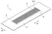
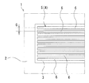
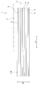
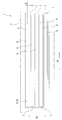
- FIG. 2 is a plan view of the joined body according to the first embodiment of the present invention.
- the perspective view of the joined body of FIG. The elements on larger scale of FIG.
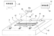
- FIG. 2 is a schematic perspective view of a laser welding device. 4 is a graph showing a relationship between an irradiation area ratio and a buckling stress.
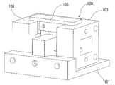
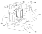
- FIG. 3 is an exploded perspective view of the crushing jig.
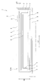
- FIG. 6 is a plan view of a joined body according to a second embodiment of the present invention.
- FIG. 10 is a plan view of a joined body according to a third embodiment of the present invention.
- FIG. 14 is a plan view of a joined body according to a fourth embodiment of the present invention.
- FIG. 14 is a plan view of a joined body according to a fifth embodiment of the present invention.
- FIG. 15 is a plan view of a joined body according to a sixth embodiment of the present invention.
- FIG. 16 is a plan view of a joined body according to a seventh embodiment of the present invention.
- FIG. 13B is a schematic view of an irradiation pattern in the joined body of FIG. 13A. The top view of the joined body concerning 8th Embodiment of this invention.
- FIG. 14B is a schematic view of an irradiation pattern in the joined body of FIG. 14A.
- FIG. 15B is a schematic view of an irradiation pattern in the joined body of FIG. 15A.
- FIG. 16B is a schematic view of an irradiation pattern in the joined body of FIG. 16A.
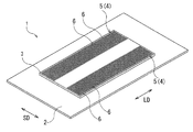
- the joined body 1 includes a blank 2 (first metal member), which is an example of a steel plate, and a reinforcing member 3 (second metal member), which is also an example of a steel plate.
- first metal member which is an example of a steel plate
- second metal member which is also an example of a steel plate.
- the reinforcing material 3 is narrower than the blank material 2.
- the reinforcing material 3 is overlaid on the blank material 2.
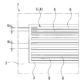
- the joined body 1 includes a joined portion 5 constituted by one continuous linear welding mark or welded portion 4.
- the blank 5 and the reinforcing member 3 are joined to each other by the joining portion 5.
- the bonded portion 5 includes ten linear portions 6 (main linear portions) extending in the longitudinal direction LD (first direction) of the reinforcing member 3.
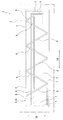
- the joined body 1 of the present embodiment is processed into a B pillar 51 which is an example of a vehicle body structural component by a hot stamp (hot press).
- a hot stamp hot press
- two reinforcing members 3 are joined to the blank 2, and each reinforcing member 3 is joined to a ridge formed by hot stamping.
- only one reinforcing member 3 is illustrated for easy understanding.
- the reinforcing member 3 is fixed to the blank 2 by, for example, laser welding using a laser welding device 41 as shown in FIG.
- the laser welding device 41 includes a table 42, a laser oscillation system 43, a moving device 44, and a control device 45.
- the blank 2 is placed on the upper surface of the table 42 and fixed to the table 42 by a jig 46.
- the reinforcing member 3 stacked on the blank 2 is fixed to the blank 2 by a jig 47.
- the reinforcing material 3 may be fixed to the blank material 2 by temporary fixing welding such as spot welding.
- the blank 2 and the reinforcing member 3 may be fixed to the table 42 by magnetic attraction generated by a magnetic field generated by a magnetic field generator disposed below the table 42.
- the laser oscillation system 43 includes components necessary for generating laser light, such as a laser oscillation element, a drive circuit, and an optical system.
- Laser light 48 is emitted downward from the laser oscillation system 43.
- the moving device 44 moves the laser oscillation system 43.
- the laser oscillation system 43 is fixed to the movable arm 44a of the moving device 44 with the laser beam 48 facing downward.
- the movable arm 44a moves the laser oscillation system 43 in two directions in the horizontal plane, that is, in the X direction and the Y direction, so that the irradiation position of the laser beam 48 moves along the joint portion 5.
- the joining portion 5 that joins the reinforcing member 3 and the blank member 2 is formed by the laser beam 48 applied to the surface of the reinforcing member 3.
- the control device 45 controls the operation of various elements of the laser welding device 41 including the laser oscillation system 43 and the moving device 44 in an integrated manner.
- the present inventors have described a joined body 1 as in the present embodiment in which a reinforcing member 3 is joined to two metal members, that is, a blank material 2, at a joining portion 5 formed by a linear welded portion 4. , Found new findings. Hereinafter, this point will be described.
- the present inventors conducted a test simulating buckling of the web surface when the joined body 1 in which the reinforcing material 3 was welded to the blank material 2 was processed into a B pillar 51 as shown in FIG. 4 by hot stamping.
- the bonded body 1 which is an elongated flat plate is attached to the crushing jig 100 shown in FIGS. 7A to 7C, and the buckling stress of the bonded body 1 when a longitudinal in-plane compressive load is applied by a press machine is measured. did.
- the elements constituting the crushing jig 100 are assembled by bolts (not shown).
- the crushing jig 100 includes a base 101 arranged on a table of a press.
- a lower holding block 102 that holds the lower end side of the joined body 1, a pair of side blocks 103, a rear block 104, and a front block 105 are fixed to the base 101.
- the upper end side of the joined body 1 is held by the upper holding block 106.
- the upper holding block 106 is held by the side blocks 103 so as to be movable only in the vertical direction.
- the front block 105 has a protruding portion 105 a facing the joined body 1.
- the compression load of the press acts on the joined body 1 via the upper holding block 106.
- the direction of the compressive load indicated by the symbol CL shown in FIG. 7C corresponds to the bending moment M (see FIG. 4) acting on the B pillar 51 which is a relatively long member at the time of a vehicle collision.
- FIG. 6 shows the measurement results of the buckling load.
- the horizontal axis shows the ratio of the joint 5 to the area of the reinforcing material 3, that is, the irradiation area ratio, and the vertical axis shows the buckling stress.
- the symbol “ ⁇ ” indicates that the joint portion 5 is composed of a plurality of linear portions 6 extending in the longitudinal direction LD of the reinforcing member 3 as in the present embodiment, that is, the linear portion 6 has a compressive load.
- CL the direction of bending moment M that is expected to act on B pillar 51.
- the symbol “ ⁇ ” indicates that the joint portion 5 is composed of a plurality of linear portions extending in the lateral direction SD (second direction) of the reinforcing member 3, that is, the linear portion 6 has a compressive load.
- a case is shown in which it is provided so as to extend in a direction perpendicular to CL (a direction perpendicular to the direction of the bending moment M that is expected to act on the B pillar 51).
- the joining portion 6 is configured by a line extending in the longitudinal direction of the reinforcing member 3, that is, the direction of the bending moment M that is assumed to act on the B pillar 51. It can be seen that the buckling strength of the B pillar 51 is increased. As described above, the present inventors have found that the strength of a component obtained by processing a joined body has a linear component extending in a direction corresponding to a load in which the joint is expected to act on the component. I found that it could be enhanced.
- the joined portion 5 includes ten straight portions 6 (main straight portions) extending in the longitudinal direction LD of the reinforcing member 3.
- the linear portion 6 has no bent portion, and can be regarded as a substantially geometric straight line.
- the linear portion 6 in the present embodiment is a straight straight line.
- the angle ⁇ formed by the linear portion 6 of the present embodiment with respect to the longitudinal direction LD is 0 degree. That is, the linear portion 6 in the present embodiment is not inclined in the short direction SL.
- the linear portions 6 are provided at regular intervals G in a direction orthogonal to the longitudinal direction LD, that is, in the short direction SD of the reinforcing member 3.
- the angle ⁇ formed by the linear portion 6 in the present embodiment with respect to the longitudinal direction LD is 0 degree.
- the linear portion 6 does not necessarily need to extend parallel to the geometrical longitudinal direction LD. That is, if the angle ⁇ is 0 degrees or more and 15 degrees or less, the buckling strength of the B pillar 51 obtained by processing and manufacturing the joined body 1 can be increased.
- the joining portion 5 includes six linear portions arranged in the transverse direction SD with a constant interval G wider than that of the first embodiment. 6 is provided. Also in this embodiment, when the joined body 1 is processed into the B pillar 51, the total length of the linear portion 6 extending in the direction of the bending moment M occupies 100% of the entire path length of the joined portion 5, and the B pillar 51 can be increased in buckling strength.
- the bonded portion 5 includes six linear portions 6 arranged in the transverse direction SD with a constant interval G therebetween.
- the joint portion 5 includes a plurality of linear portions 7 that respectively connect one ends of a pair of linear portions 6 adjacent to each other in the transverse direction SD, and each linear portion 7 is orthogonal to the longitudinal direction LD.
- Direction that is, in the short direction SD.
- the straight portion 6 and the straight portion 7 form a crank shape.
- the total path length of the joint portion 5 in the present embodiment is the sum of the total length of the linear portions 6 and the total length of the linear portions 7.
- the total length of the linear portion 6 extending in the longitudinal direction LD occupies most of the entire path length of the joint portion 5, that is, about 97%. Therefore, the buckling strength of the B pillar 51 obtained by processing and manufacturing the joined body 1 can be further increased.
- the joint portion 5 extends in the longitudinal direction LD and is connected to seven linear portions 6 arranged in the lateral direction SD, and a short portion that sequentially connects them. And six linear portions 7 extending in the hand direction SD.
- the straight portion 6 and the straight portion 7 form a spiral shape.
- the joined portion 5 extends in the longitudinal direction LD and has five linear portions 6 arranged in the transverse direction SD, and a short portion that sequentially connects them. And four linear portions 7 extending in the hand direction SD.
- the straight portion 6 and the straight portion 7 form a spiral shape.
- two types of inclined linear portions 8, 9 inclined in different directions with respect to the longitudinal direction LD are provided alternately and repeatedly from the innermost end of the spiral shape. Since the joint 5 includes the linear portion 6 extending in the longitudinal direction LD, the buckling strength of the B pillar 51 obtained by processing and manufacturing the joint 1 can be increased.
- the total length of the linear portion 6 extending in the longitudinal direction LD occupies most of the entire path length of the joint portion 5, that is, about 74%. Therefore, the buckling strength of the B pillar 51 obtained by processing and manufacturing the joined body 1 can be further increased.
- the joint portion 5 of the present embodiment includes nine linear portions 6 extending in the longitudinal direction LD and arranged in the lateral direction SD.
- the distance Ge between the linear portions 6 in the end region of the reinforcing member 3 in the short direction SD is smaller than the distance Gc between the linear portions 6 in the central region of the reinforcing member 3 in the short direction SD. That is, the arrangement density of the linear portions 6 in the end region of the reinforcing member 3 in the lateral direction SD is higher than the arrangement density of the linear portions 6 in the central region of the reinforcing member 3 in the lateral direction SD.
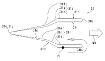
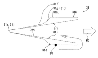
- the irradiation pattern 31 in FIG. 13B has two wedge-shaped portions each having a shape that expands in the direction of movement MD, that is, an outer wedge-shaped portion 31b, and an inner wedge disposed inside the outer wedge-shaped portion 31b. And a shape part 31c.
- the outer wedge-shaped portion 31b includes a pair of oblique sides 31d that are inclined with respect to the moving direction MD as a whole, and an arc-shaped distal end 31e that connects these oblique sides 31d.
- Each of the oblique side portions 31d includes a linear first portion 31f having one end connected to the distal end portion 31e, a linear second portion 31g having one end connected to the other end of the first portion 31f, and a second portion 31g.
- Has a third portion 31h having one end connected to the other end of the third portion 31h.
- the angle with respect to the moving direction MD is larger in the order of the second portion 31g, the first portion 31f, and the third portion 31h, and the third portion 31h extends substantially in the same direction as the moving direction MD.
- the length of the second portion 31g is shorter than the first portion 31f and the second portion 31h.
- the inner wedge-shaped portion 31c includes a pair of linear oblique sides 31i that are inclined with respect to the moving direction MD, and an arc-shaped tip 31j that connects these oblique sides 31i.
- the tip 31j of the inner wedge 31c substantially overlaps the tip 31e of the outer wedge 31b.
- Each hypotenuse portion 31i has a linear first portion 31m having one end connected to the distal end portion 31j, a linear second portion 31n having one end connected to the other end of the first portion 31m, and a second portion 31n.
- Has a third portion 31o whose one end is connected to the other end of the third portion 31o.
- Each oblique side 31d of the outer wedge-shaped part 31b is connected to an adjacent one of the oblique sides 31i of the inner wedge-shaped part 31c via an arc-shaped inverted part 31k.
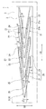
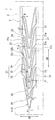
- the joint 5 obtained by the irradiation pattern 31 in FIG. 13B includes a plurality of first linear portions 21 (first main linear portions) and a plurality of second linear portions 22 (second 2 main linear portions).
- the individual first linear portions 21 generally extend in the longitudinal direction LD, but are inclined in the transverse direction SD as a whole to the lower right in the figure.
- the first linear portion 21 includes a first portion 21a extending in the longitudinal direction LD, a second portion 21b having one end connected to the first portion 21a, and a third portion 21c having one end connected to the second portion 21b. .
- the angle ⁇ between the first portion 21a and the longitudinal direction LD is set to 0 degree.
- the angle ⁇ formed by the third portion 21c with respect to the longitudinal direction LD is set to be more than 0 degrees and 15 degrees or less.
- the individual second linear portions 22 generally extend in the longitudinal direction LD, but are inclined as a whole to the right in the transverse direction SD in the figure.
- the second linear portion 22 includes a first portion 22a extending in the longitudinal direction LD, a second portion 22b having one end connected to the first portion 22a, and a third portion 22c having one end connected to the second portion 22b.
- the angle ⁇ between the first portion 22a and the longitudinal direction LD is set to 0 degree.
- the angle ⁇ formed by the third portion 22c with respect to the longitudinal direction LD is set to be more than 0 degrees and 15 degrees or less.
- the first unit 26 is constituted by the pair of first linear portions 21 and one inverting portion 23 (first inverting portion) connecting these.
- the second unit 27 is constituted by the pair of second linear portions 22 and one inverting portion 24 (second inverting portion) connecting these.
- the first unit 26 and the second unit 27 are alternately and repeatedly arranged via a reversing unit 25 (third reversing unit).
- the first linear portion 21 (excluding the second portion 21 b) and the second linear portion 22 (the second linear portion 22) whose angle ⁇ with respect to the longitudinal direction LD is 0 ° or more and 15 ° or less. (Excluding the two portions 22b), so that the buckling strength of the B pillar 51 obtained by processing and manufacturing the joined body 1 can be increased.
- the first linear portion 21 (excluding the second portion 21b) and the second linear portion 22 whose angle ⁇ with respect to the longitudinal direction LD is 0 ° or more and 15 ° or less.
- the total length of the joint portion 5 (excluding the second portion 22b), that is, the total length of the portion extending along the longitudinal direction LD occupies about 77% of the entire path length of the joint portion 5.
- the arrangement density of the first linear portion 21 and the second linear portion 22 in the end region in the lateral direction SD of the reinforcing member 3 depends on the lateral direction of the reinforcing member 3. It is higher than the arrangement density of the first linear portions 21 and the second linear portions 22 in the central region in SD.
- each of the first linear portions 21 and the second linear portions 22 is different from the other first linear portions 21 and the second linear portions 22, and the inverting portions 23 to 25. Does not intersect with any of Therefore, no part of the joint 5 forms a closed figure. Therefore, gas generated at the time of welding for forming the joint portion 5 is discharged to the outside from the mating surface of the blank material 2 and the joint material 3, so that a defect such as a blow hole does not occur at the connection portion.
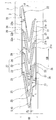
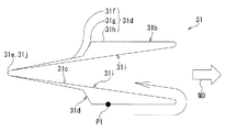
- the joint 5 shown in FIG. 14A is obtained by moving the irradiation pattern 31 shown in FIG. 14B in the moving direction MD.
- the oblique side portion 31d of the outer wedge-shaped portion 31b has a linear first portion 31f having one end connected to the distal end portion 31e, and a third portion extending substantially in the same direction as the moving direction MD. And a portion 31h.
- the hypotenuse 31i of the inner wedge 31c is linear.
- Other shapes of the irradiation pattern 31 in FIG. 14B are the same as those in FIG. 13B.
- elements common to FIG. 13B are denoted by the same reference numerals.
- one of the pair of first linear portions 21 that constitute the first unit 26 is located outside the reinforcing member 3 in the width direction.
- those located inside the reinforcing member 3 in the width direction have an angle ⁇ with respect to the longitudinal direction LD of more than 0 ° and 15 ° or less. It is a set single straight line.
- the first portion 22a includes a second portion 22b in which the angle ⁇ is greater than 0 degrees and equal to or less than 15 degrees.
- those located in the width direction of the reinforcing member 3 have an angle ⁇ with respect to the longitudinal direction LD of more than 0 ° and 15 ° or less. It is a set single straight line.
- Other shapes of the joint 5 in FIG. 14A are the same as those in FIG. 13A.
- elements common to FIG. 13B are denoted by the same reference numerals.
- the 14A has the first linear portion 21 and the second linear portion 22 in which the angle ⁇ with respect to the longitudinal direction LD is 0 ° or more and 15 ° or less, so that the joined body 1 is processed.
- the buckling strength of the manufactured B pillar 51 can be increased.
- the total length of the first linear portion 21 and the second linear portion 22 whose angle ⁇ with respect to the longitudinal direction LD is 0 ° or more and 15 ° or less is about 96% of the total path length of the joint portion 5. Occupy. With this configuration, the buckling strength of the B pillar 51 obtained by processing and manufacturing the joined body 1 can be further increased.
- the arrangement density of the first linear portion 21 and the second linear portion 22 in the end region of the reinforcing member 3 in the short direction SD is the first straight line in the central region of the reinforcing member 3 in the short direction SD. Since the density is higher than the arrangement density of the linear portion 21 and the second linear portion 22, when the reinforcing material 3 is processed into the B pillar 51, peeling from the blank 2 in the end region in the short direction SD of the reinforcing material 3 is prevented. Can be suppressed or prevented. Further, the individual first linear portions 21 and second linear portions 22 do not intersect with any of the other first linear portions 21 and second linear portions 22 and any of the reversing portions 23 to 25. Gas generated during welding for forming the joint portion 5 can be discharged to the outside.
- the joint 5 shown in FIG. 15A is obtained by moving the irradiation pattern 31 shown in FIG. 15B in the moving direction MD.
- the irradiation pattern 31 shown in FIG. 15B is the same as the irradiation pattern 31 of FIG. 13B except that the oblique side 31i of the inner wedge-shaped portion 31c is linear.
- the angle ⁇ formed by the pair of first linear portions 21 that are located inside the reinforcing member 3 in the width direction among the pair of first linear portions 21 with respect to the longitudinal direction LD is 0 degrees. And a single straight line set at 15 degrees or less. Further, in the joint portion 5 in FIG. 15A, the angle ⁇ formed by the pair of the second linear portions 22 that are located inside the reinforcing member 3 in the width direction among the pair of second linear portions 22 configuring the second unit 27 has an angle ⁇ with respect to the longitudinal direction LD. It is a single straight line set at more than 0 degrees and 15 degrees or less. Except for these points, the joint 5 of FIG. 15A is similar to that of FIG. 13A. In FIG. 15A, elements common to FIG. 13A are denoted by the same reference numerals.
- the 15A has the first linear portion 21 and the second linear portion 22 in which the angle ⁇ with respect to the longitudinal direction LD is 0 ° or more and 15 ° or less, so that the joined body 1 is processed.
- the buckling strength of the manufactured B pillar 51 can be increased. Further, the total length of the first linear portion 21 and the second linear portion 22 whose angle ⁇ with respect to the longitudinal direction LD is 0 ° or more and 15 ° or less is about 89% of the total path length of the joint portion 5. Occupy. With this configuration, the buckling strength of the B pillar 51 obtained by processing and manufacturing the joined body 1 can be further increased.
- the arrangement density of the first linear portion 21 and the second linear portion 22 in the end region of the reinforcing member 3 in the short direction SD is the first straight line in the central region of the reinforcing member 3 in the short direction SD. Since the density is higher than the arrangement density of the linear portion 21 and the second linear portion 22, when the reinforcing material 3 is processed into the B pillar 51, peeling from the blank 2 in the end region in the short direction SD of the reinforcing material 3 is prevented. Can be suppressed or prevented. Further, the individual first linear portions 21 and second linear portions 22 do not intersect with any of the other first linear portions 21 and second linear portions 22 and any of the reversing portions 23 to 25. Gas generated during welding for forming the joint portion 5 can be discharged to the outside.
- (Tenth embodiment) 16A is obtained by moving the irradiation pattern 31 in the moving direction MD similar to that of FIG. 15B, as shown in FIG. 16B.
- the joint 5 of FIG. 16A has an intersection 28 where the first linear portion 21 overlaps the inversion portion 23, and an intersection 29 where the second linear portion 22 overlaps the inversion portion 24, except for the point shown in FIG.
- It is similar to that of 16A includes the first linear portion 21 and the second linear portion 22 whose angle ⁇ with respect to the longitudinal direction LD is 0 ° or more and 15 ° or less, and thus is obtained by processing the joined body 1. Buckling strength of the B pillar 51 can be increased.
- the total length of the first linear portion 21 and the second linear portion 22 whose angle ⁇ with respect to the longitudinal direction LD is 0 ° or more and 15 ° or less is about 88% of the total path length of the joint portion 5 Therefore, the buckling strength of the B pillar 51 obtained by processing the joined body 1 can be further increased. Further, since the arrangement density of the first linear portion 21 and the second linear portion 22 in the end region of the reinforcing member 3 in the short direction SD is high, when the joint 1 is processed into the B pillar 51, The peeling of the material 3 from the blank material 2 can be suppressed or prevented.
- the short direction SD of the first linear portion 21 and the second linear portion 22 is used. Is preferably 15 mm or less.
- the ratio of the total length of the linear portion extending in the longitudinal direction LD that is, the angle ⁇ being equal to or greater than 0 degree and equal to or less than 15 degrees, to the entire path length of the joint portion 5 is equal to the longitudinal length of the reinforcing member 3. This is a numerical value when the ratio between the dimension in the direction LD and the dimension in the lateral direction SD is 6: 1. Further, in the seventh to tenth embodiments, the ratio of the total length of the linear portion extending in the longitudinal direction LD to the entire path length of the joint 5 is the dimension of the reinforcing member 3 in the short direction SD, that is, the reinforcing member 3 This is a numerical value when the width is 40 mm.
- the size of the reinforcing member 3 is not limited to these, and can be changed as appropriate.
- the ratio of the total length of the linear portion extending in the longitudinal direction LD to the total path length of the joint 5 is equal to or more than 74% in accordance with the dimensions of the reinforcing member 3 in the longitudinal direction LD and the transverse direction SD. It is similarly changed to be 97% or less.
- one joint 5 is provided for one reinforcing member 3.
- a plurality of joints 5 may be provided for one reinforcing member 3.
- each joint portion 5 is the same as or similar to that of the first embodiment (see FIGS. 1 to 3), and includes a plurality of linear portions 6 extending in the longitudinal direction LD.
- the individual joints 5 may be the same as or similar to those of the second to tenth embodiments.
- the total length of the joints 5 having the total length of the linear portions extending in the longitudinal direction LD is provided for each individual joint 5.
- the ratio to the path length is set to 74% or more and 97% or less.
Landscapes
- Engineering & Computer Science (AREA)
- Physics & Mathematics (AREA)
- Mechanical Engineering (AREA)
- Optics & Photonics (AREA)
- Plasma & Fusion (AREA)
- Chemical & Material Sciences (AREA)
- Combustion & Propulsion (AREA)
- Transportation (AREA)
- Thermal Sciences (AREA)
- Body Structure For Vehicles (AREA)
- Laser Beam Processing (AREA)
Priority Applications (3)
| Application Number | Priority Date | Filing Date | Title |
|---|---|---|---|
| US17/256,090 US20210269098A1 (en) | 2018-07-06 | 2019-06-03 | Joined body |
| CN201980045365.7A CN112399902A (zh) | 2018-07-06 | 2019-06-03 | 接合体 |
| EP19831228.2A EP3819066A4 (de) | 2018-07-06 | 2019-06-03 | Verbindungsstelle |
Applications Claiming Priority (2)
| Application Number | Priority Date | Filing Date | Title |
|---|---|---|---|
| JP2018-129355 | 2018-07-06 | ||
| JP2018129355A JP2020006401A (ja) | 2018-07-06 | 2018-07-06 | 接合体 |
Publications (1)
| Publication Number | Publication Date |
|---|---|
| WO2020008772A1 true WO2020008772A1 (ja) | 2020-01-09 |
Family
ID=69060650
Family Applications (1)
| Application Number | Title | Priority Date | Filing Date |
|---|---|---|---|
| PCT/JP2019/022014 Ceased WO2020008772A1 (ja) | 2018-07-06 | 2019-06-03 | 接合体 |
Country Status (5)
| Country | Link |
|---|---|
| US (1) | US20210269098A1 (de) |
| EP (1) | EP3819066A4 (de) |
| JP (1) | JP2020006401A (de) |
| CN (1) | CN112399902A (de) |
| WO (1) | WO2020008772A1 (de) |
Cited By (1)
| Publication number | Priority date | Publication date | Assignee | Title |
|---|---|---|---|---|
| JP2025523147A (ja) * | 2022-07-29 | 2025-07-17 | ヌオーヴォ・ピニォーネ・テクノロジー・ソチエタ・レスポンサビリタ・リミタータ | シュラウド付きインペラを製造するための方法 |
Families Citing this family (5)
| Publication number | Priority date | Publication date | Assignee | Title |
|---|---|---|---|---|
| JP7063930B2 (ja) * | 2020-03-13 | 2022-05-09 | フタバ産業株式会社 | 成形品の製造方法及び成形品 |
| CN114475796B (zh) * | 2022-02-11 | 2023-04-25 | 湖州师范学院 | 一种提高车辆b柱抗型变强度的方法 |
| DE102022106540A1 (de) * | 2022-03-21 | 2023-09-21 | Audi Aktiengesellschaft | Verfahren zum Laserstrahlschweißen |
| CN117444391A (zh) * | 2023-09-25 | 2024-01-26 | 海目星激光科技集团股份有限公司 | 接线盒激光焊接方法、装置、设备及存储介质 |
| JP2026065263A (ja) * | 2024-10-03 | 2026-04-15 | 株式会社J‐Max | レーザ溶接構造体の製造方法 |
Citations (3)
| Publication number | Priority date | Publication date | Assignee | Title |
|---|---|---|---|---|
| JP2001507993A (ja) | 1997-01-14 | 2001-06-19 | コスマ パワーレーザーズ リミテッド | テイラードブランク |
| JP2014015206A (ja) | 2010-09-16 | 2014-01-30 | Nippon Steel & Sumitomo Metal | 成形部材およびその製造方法 |
| JP2016064725A (ja) * | 2014-09-24 | 2016-04-28 | 富士重工業株式会社 | 車体骨格構造、及びその製造方法 |
Family Cites Families (17)
| Publication number | Priority date | Publication date | Assignee | Title |
|---|---|---|---|---|
| US4223201A (en) * | 1978-12-14 | 1980-09-16 | United Technologies Corporation | Laser welding apparatus for shipyard panel shops |
| DE3478906D1 (en) * | 1983-04-20 | 1989-08-17 | British Shipbuilders Eng | Laser-beamwelding |
| EP0857526B1 (de) * | 1997-02-08 | 1999-10-27 | Volkswagen Aktiengesellschaft | Umformteil mit einer bereichsweise ausgebildeten Mehrfachblechstruktur |
| EP1752250B1 (de) * | 2004-05-18 | 2012-05-23 | Kawasaki Jukogyo Kabushiki Kaisha | Laserschweissverfahren, lasergeschweisste verbindung, aussenplatte und struktur für rollendes material |
| DE102009016805B4 (de) * | 2009-04-09 | 2014-04-03 | Alanod Gmbh & Co. Kg | Verfahren zum Laserverschweißen eines Verbundmaterials mit einem Bauteil |
| DE102011101700A1 (de) * | 2010-12-21 | 2012-06-21 | Sitech Sitztechnik Gmbh | Fahrzeugsitz mit laserverfestigten Bereichen |
| EP2926939B1 (de) * | 2012-11-29 | 2017-11-15 | Nippon Steel & Sumitomo Metal Corporation | Verfahren zur herstellung einer filet-lichtbogenschweissverbindung und filet- lichtbogenschweissverbindung |
| JP6091974B2 (ja) * | 2013-04-16 | 2017-03-08 | 株式会社神戸製鋼所 | 溶接物の製造方法、溶接方法、溶接装置 |
| KR101943173B1 (ko) * | 2014-02-06 | 2019-01-28 | 신닛테츠스미킨 카부시키카이샤 | 겹침 용접 방법, 겹침 조인트, 겹침 조인트의 제조 방법 및 자동차용 부품 |
| DE102014101907A1 (de) * | 2014-02-14 | 2015-08-20 | Thyssenkrupp Ag | Metallblech mit lokaler metallischer Verstärkung und Verfahren zu dessen Herstellung |
| GB2532001B (en) * | 2014-10-24 | 2017-09-27 | Gkn Aerospace Sweden Ab | Crack stopper for welds |
| CN104527805A (zh) * | 2014-12-17 | 2015-04-22 | 无锡朗贤汽车组件研发中心有限公司 | 车辆的b柱及制造方法 |
| CN205421229U (zh) * | 2016-03-25 | 2016-08-03 | 何晓婷 | 一种加筋热熔连接的土工格室 |
| JP2018086664A (ja) * | 2016-11-28 | 2018-06-07 | 武藤工業株式会社 | 溶接装置、溶接方法、三次元造形装置、及び三次元造形方法 |
| CN106903430A (zh) * | 2017-03-17 | 2017-06-30 | 敏实汽车技术研发有限公司 | 一种汽车门框a柱板、b柱板、c柱板焊接方法 |
| JP6994324B2 (ja) * | 2017-08-31 | 2022-01-14 | 株式会社神戸製鋼所 | 接合体の製造方法および製造装置 |
| JP6966977B2 (ja) * | 2018-06-20 | 2021-11-17 | 株式会社神戸製鋼所 | レーザ溶接方法及びレーザ溶接装置 |
-
2018
- 2018-07-06 JP JP2018129355A patent/JP2020006401A/ja active Pending
-
2019
- 2019-06-03 EP EP19831228.2A patent/EP3819066A4/de not_active Withdrawn
- 2019-06-03 WO PCT/JP2019/022014 patent/WO2020008772A1/ja not_active Ceased
- 2019-06-03 CN CN201980045365.7A patent/CN112399902A/zh active Pending
- 2019-06-03 US US17/256,090 patent/US20210269098A1/en not_active Abandoned
Patent Citations (3)
| Publication number | Priority date | Publication date | Assignee | Title |
|---|---|---|---|---|
| JP2001507993A (ja) | 1997-01-14 | 2001-06-19 | コスマ パワーレーザーズ リミテッド | テイラードブランク |
| JP2014015206A (ja) | 2010-09-16 | 2014-01-30 | Nippon Steel & Sumitomo Metal | 成形部材およびその製造方法 |
| JP2016064725A (ja) * | 2014-09-24 | 2016-04-28 | 富士重工業株式会社 | 車体骨格構造、及びその製造方法 |
Non-Patent Citations (1)
| Title |
|---|
| See also references of EP3819066A4 |
Cited By (2)
| Publication number | Priority date | Publication date | Assignee | Title |
|---|---|---|---|---|
| JP2025523147A (ja) * | 2022-07-29 | 2025-07-17 | ヌオーヴォ・ピニォーネ・テクノロジー・ソチエタ・レスポンサビリタ・リミタータ | シュラウド付きインペラを製造するための方法 |
| US20250332663A1 (en) * | 2022-07-29 | 2025-10-30 | Nuovo Pignone Tecnologie -S.R.L. | Method for manufacturing a shrouded impeller |
Also Published As
| Publication number | Publication date |
|---|---|
| US20210269098A1 (en) | 2021-09-02 |
| CN112399902A (zh) | 2021-02-23 |
| EP3819066A1 (de) | 2021-05-12 |
| JP2020006401A (ja) | 2020-01-16 |
| EP3819066A4 (de) | 2022-04-13 |
Similar Documents
| Publication | Publication Date | Title |
|---|---|---|
| WO2020008772A1 (ja) | 接合体 | |
| JP5382233B1 (ja) | パネル接合構造 | |
| CN102476248A (zh) | 嵌板结构体的制造方法 | |
| JP5801784B2 (ja) | 連結部材および筐体 | |
| CN112888866A (zh) | 连结部件以及框体 | |
| JP4359291B2 (ja) | 被接合部材 | |
| CN102026767B (zh) | 用于以与接合线交叉的定位焊接带对两个部件定位的方法 | |
| JP6462488B2 (ja) | 薄板回路基板、フレキシャー、及び溶接方法 | |
| JPH11239890A (ja) | 溶接構造 | |
| JP6124702B2 (ja) | 座屈拘束ブレース | |
| JP5090387B2 (ja) | リードフレーム | |
| JP5216057B2 (ja) | 乗客コンベア | |
| JP2021060087A (ja) | 板材連結機構 | |
| KR102231825B1 (ko) | 웨이브 스프링 | |
| JP7832037B2 (ja) | 接合部材、接合部材の製造方法、柱と梁との接合構造 | |
| JP6871989B2 (ja) | 構造物の柱脚構造およびベースプレート | |
| WO2021220326A1 (ja) | 樹脂部材の継手構造、電気機器の樹脂筐体、及びレーザ溶着方法 | |
| JP2014100718A (ja) | 補強方法および補強構造 | |
| JP2014122462A (ja) | 座屈拘束ブレース | |
| KR20260035081A (ko) | 건 암 및 접합 장치 | |
| KR101020556B1 (ko) | 차체의 조인트 어셈블리 | |
| CN209926973U (zh) | 用作板翅式换热器封头的异形槽铝 | |
| JP2019217534A (ja) | レーザ溶接方法及びレーザ溶接装置 | |
| JP4345586B2 (ja) | レーザー溶接方法 | |
| JP2006150441A (ja) | 高負荷性を有する直線溶接継目及びその形成方法 |
Legal Events
| Date | Code | Title | Description |
|---|---|---|---|
| 121 | Ep: the epo has been informed by wipo that ep was designated in this application |
Ref document number: 19831228 Country of ref document: EP Kind code of ref document: A1 |
|
| NENP | Non-entry into the national phase |
Ref country code: DE |