WO2020008778A1 - 切削加工機及び切削加工方法 - Google Patents
切削加工機及び切削加工方法 Download PDFInfo
- Publication number
- WO2020008778A1 WO2020008778A1 PCT/JP2019/022104 JP2019022104W WO2020008778A1 WO 2020008778 A1 WO2020008778 A1 WO 2020008778A1 JP 2019022104 W JP2019022104 W JP 2019022104W WO 2020008778 A1 WO2020008778 A1 WO 2020008778A1
- Authority
- WO
- WIPO (PCT)
- Prior art keywords
- tool
- processing
- cutting
- diameter correction
- path
- Prior art date
- Legal status (The legal status is an assumption and is not a legal conclusion. Google has not performed a legal analysis and makes no representation as to the accuracy of the status listed.)
- Ceased
Links
Images



Classifications
-
- B—PERFORMING OPERATIONS; TRANSPORTING
- B23—MACHINE TOOLS; METAL-WORKING NOT OTHERWISE PROVIDED FOR
- B23K—SOLDERING OR UNSOLDERING; WELDING; CLADDING OR PLATING BY SOLDERING OR WELDING; CUTTING BY APPLYING HEAT LOCALLY, e.g. FLAME CUTTING; WORKING BY LASER BEAM
- B23K26/00—Working by laser beam, e.g. welding, cutting or boring
-
- B—PERFORMING OPERATIONS; TRANSPORTING
- B23—MACHINE TOOLS; METAL-WORKING NOT OTHERWISE PROVIDED FOR
- B23K—SOLDERING OR UNSOLDERING; WELDING; CLADDING OR PLATING BY SOLDERING OR WELDING; CUTTING BY APPLYING HEAT LOCALLY, e.g. FLAME CUTTING; WORKING BY LASER BEAM
- B23K26/00—Working by laser beam, e.g. welding, cutting or boring
- B23K26/08—Devices involving relative movement between laser beam and workpiece
-
- B—PERFORMING OPERATIONS; TRANSPORTING
- B23—MACHINE TOOLS; METAL-WORKING NOT OTHERWISE PROVIDED FOR
- B23K—SOLDERING OR UNSOLDERING; WELDING; CLADDING OR PLATING BY SOLDERING OR WELDING; CUTTING BY APPLYING HEAT LOCALLY, e.g. FLAME CUTTING; WORKING BY LASER BEAM
- B23K26/00—Working by laser beam, e.g. welding, cutting or boring
- B23K26/08—Devices involving relative movement between laser beam and workpiece
- B23K26/082—Scanning systems, i.e. devices involving movement of the laser beam relative to the laser head
-
- B—PERFORMING OPERATIONS; TRANSPORTING
- B23—MACHINE TOOLS; METAL-WORKING NOT OTHERWISE PROVIDED FOR
- B23K—SOLDERING OR UNSOLDERING; WELDING; CLADDING OR PLATING BY SOLDERING OR WELDING; CUTTING BY APPLYING HEAT LOCALLY, e.g. FLAME CUTTING; WORKING BY LASER BEAM
- B23K26/00—Working by laser beam, e.g. welding, cutting or boring
- B23K26/36—Removing material
-
- B—PERFORMING OPERATIONS; TRANSPORTING
- B23—MACHINE TOOLS; METAL-WORKING NOT OTHERWISE PROVIDED FOR
- B23Q—DETAILS, COMPONENTS, OR ACCESSORIES FOR MACHINE TOOLS, e.g. ARRANGEMENTS FOR COPYING OR CONTROLLING; MACHINE TOOLS IN GENERAL CHARACTERISED BY THE CONSTRUCTION OF PARTICULAR DETAILS OR COMPONENTS; COMBINATIONS OR ASSOCIATIONS OF METAL-WORKING MACHINES, NOT DIRECTED TO A PARTICULAR RESULT
- B23Q15/00—Automatic control or regulation of feed movement, cutting velocity or position of tool or work
-
- G—PHYSICS
- G05—CONTROLLING; REGULATING
- G05B—CONTROL OR REGULATING SYSTEMS IN GENERAL; FUNCTIONAL ELEMENTS OF SUCH SYSTEMS; MONITORING OR TESTING ARRANGEMENTS FOR SUCH SYSTEMS OR ELEMENTS
- G05B19/00—Program-control systems
- G05B19/02—Program-control systems electric
- G05B19/18—Numerical control [NC], i.e. automatically operating machines, in particular machine tools, e.g. in a manufacturing environment, so as to execute positioning, movement or co-ordinated operations by means of program data in numerical form
- G05B19/4093—Numerical control [NC], i.e. automatically operating machines, in particular machine tools, e.g. in a manufacturing environment, so as to execute positioning, movement or co-ordinated operations by means of program data in numerical form characterised by part programming, e.g. entry of geometrical information as taken from a technical drawing, combining this with machining and material information to obtain control information, named part program, for the NC machine
Definitions
- the present disclosure relates to a cutting machine such as a laser machine for irradiating a processing object by irradiating a laser beam and a cutting method.
- a laser processing machine that processes a processing object by irradiating a laser beam to produce a product having a predetermined shape is widely used.
- the laser processing machine cuts a processing target by tool diameter correction in consideration of a cutting amount by a laser beam so that a product is manufactured with a predetermined shape.
- Patent Literature 1 describes an example of a laser processing machine that cuts a processing target object by correcting a tool diameter.
- the laser beam in a state where the relative position between a nozzle that emits a laser beam and a processing table on which a processing object is mounted is fixed, the laser beam usually has a circular shape, so that the cutting trace also has a circular shape. .
- the cutting trace Even in a machining center provided with a plurality of types of rotary tools, the cutting trace usually has a circular shape when the position coordinates of the rotary tools are fixed.
- the cutting trace usually has a circular shape in a state where the position coordinates where high-pressure water is injected are fixed. Accordingly, the tool diameter correction is based on the premise that the cutting trace in a state where the position coordinates of the cutting tool such as the nozzle, the rotary tool, and the high-pressure water is fixed is circular.
- a cutting machine such as a laser beam machine sets a radius of a cutting trace by a cutting tool or a half width of a cutting trace as a tool diameter correction amount, shifts the tool by the tool diameter correction amount, and shifts a workpiece.
- the trajectory during cutting is controlled.
- tool diameter correction does not correspond to a case where a cutting trace is non-circular.
- One or more embodiments include a cutting machine capable of accurately correcting the tool diameter of a cutting tool, even if a cutting trace in a state where the position coordinates of the cutting tool is fixed is non-circular;
- An object is to provide a cutting method.
- a processing machine body for cutting a processing object
- an NC device for controlling the processing machine body, wherein the NC device includes the processing object.
- the tool diameter of a cutting tool for machining the object Based on a machining program and machining conditions set based on product shape information including dimensions and shape of the final machined product obtained by machining, the tool diameter of a cutting tool for machining the object to be machined.
- a tool diameter correction amount calculating unit for generating tool diameter correction information for correcting, and generating a tool diameter correction control signal including cutting correction conditions based on the processing program, the processing conditions, and the tool diameter correction information.
- the tool diameter correction amount calculation unit recognizes a tool trajectory included in the machining conditions, determines whether a plurality of machining surface formation positions exist in the tool trajectory, If it is determined that there is a processing surface forming position of the selected, the processing surface selection position is selected from the plurality of processing surface forming positions, based on the processing program and the processing conditions and the selected processing surface forming position.
- a cutting machine is provided in which the tool diameter correction information for correcting the tool diameter of the tool path is generated, and the processing surface forming position is a position where the tool diameter is the maximum in the tool path.
- the processing program and the processing conditions are determined based on the product shape information including the dimensions and the shape of the final processed product obtained by cutting the workpiece.
- Set, included in the machining conditions corresponds to a cutting tool for cutting a workpiece, and recognizes a tool trajectory having a non-circular shape, and determines whether a plurality of machining surface forming positions exist in the tool trajectory. It is determined whether or not there is a plurality of processing surface formation positions, and when it is determined that there is a plurality of processing surface formation positions, an arbitrary processing surface formation position is selected from the plurality of processing surface formation positions, and the processing program and the processing conditions are selected.
- tool radius correction information for compensating the tool radius of the tool path is generated, and based on the machining program, the machining conditions, and the tool radius compensation information, cutting machining assistance is generated.
- Generating a tool diameter correction control signal including a condition generating a drive control signal for controlling a processing machine body based on the tool diameter correction control signal, controlling the tool trajectory based on the drive control signal,
- a cutting method is provided in which the processing surface forming position is a position where the tool diameter becomes maximum in the tool path.
- the tool diameter of the cutting tool can be accurately determined. It can be corrected well.
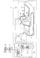
- FIG. 1 is a diagram illustrating an example of the overall configuration of a cutting machine according to one or more embodiments.
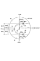
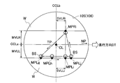
- FIG. 2 is a diagram illustrating a relationship between a nozzle and a tool path.
- FIG. 3 is a diagram illustrating a configuration example of a tool path control unit.
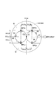
- FIG. 4 is a diagram illustrating a relationship between a nozzle and a tool path.
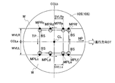
- FIG. 5 is a diagram illustrating a relationship between a nozzle and a tool path.
- FIG. 6 is a diagram illustrating a relationship between a nozzle and a tool path.
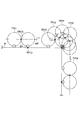
- FIG. 7 is a diagram illustrating the relationship between the nozzle trajectory and the tool trajectory.
- FIG. 8 is a diagram illustrating the relationship between the nozzle trajectory and the tool trajectory.
- FIG. 9 is a flowchart illustrating an example of a cutting method according to one or more embodiments.
- the cutting machine 1 includes a laser oscillator 10, a machine body 100, and an NC device (numerical control device) 200.
- the NC device 200 controls the laser oscillator 10 and the processing machine main body 100.
- the laser oscillator 10 generates and emits a laser beam.
- the laser beam emitted from the laser oscillator 10 is transmitted to the processing machine main body 100 via the process fiber 11.
- the processing machine body 100 cuts the processing object W by irradiating the processing object W with a laser beam and changing the relative position between the processing object W and the beam spot of the laser beam.
- the laser oscillator 10 a laser oscillator that amplifies the excitation light emitted from the laser diode and emits a laser beam of a predetermined wavelength, or a laser oscillator that directly uses the laser beam emitted from the laser diode is preferable.
- the laser oscillator 10 is, for example, a solid-state laser oscillator, a fiber laser oscillator, a disk laser oscillator, or a direct diode laser oscillator (DDL oscillator).
- the laser oscillator 10 emits a 1 ⁇ m band laser beam having a wavelength of 900 nm to 1100 nm.
- the fiber laser oscillator emits a laser beam having a wavelength of 1060 nm to 1080 nm
- the DDL oscillator emits a laser beam having a wavelength of 910 nm to 950 nm.
- the processing machine main body 100 includes a processing table 101 on which a processing target object W is placed, a gate-shaped X-axis carriage 102, a Y-axis carriage 103, a processing unit 104, and a tool path control unit 300.
- the workpiece W is a sheet metal made of, for example, stainless steel.
- the workpiece may be an iron-based sheet metal other than stainless steel, or may be an aluminum, aluminum alloy, copper steel, or other sheet metal.
- the laser beam emitted from the laser oscillator 10 is transmitted to the processing unit 104 of the processing machine main body 100 via the process fiber 11.
- the tool trajectory controller 300 is housed inside the processing unit 104.
- the X-axis carriage 102 is configured to be movable on the processing table 101 in the X-axis direction.
- the Y-axis carriage 103 is configured to be movable on the X-axis carriage 102 in the Y-axis direction orthogonal to the X-axis.
- the X-axis carriage 102 and the Y-axis carriage 103 move the processing unit 104 in the X-axis direction, the Y-axis direction, or any combined direction of the X-axis and the Y-axis along the surface of the workpiece W. Functions as a mechanism.
- the processing unit main body 100 may be configured such that the processing unit 104 has a fixed position and the processing object W moves. .
- the processing machine body 100 only needs to have a moving mechanism that relatively moves the processing unit 104 with respect to the surface of the processing target object W.
- a nozzle 106 is attached to the processing unit 104.
- a circular opening 105 is formed at the tip of the nozzle 106.
- the laser beam transmitted to the processing unit 104 is emitted from the opening 105 of the nozzle 106 and irradiates the workpiece W.
- the processing unit 104 is supplied with an assist gas such as nitrogen or air.
- the assist gas may be oxygen, and the mixing ratio between nitrogen and oxygen can be arbitrarily set depending on whether the purpose is to suppress oxidation or to utilize heat of oxidation reaction.
- the laser beam is applied to the workpiece W from the opening 105, and the assist gas is blown from the opening 105 onto the workpiece W.
- the assist gas discharges a melt within the kerf width where the workpiece W has melted.
- the tool trajectory controller 300 functions as a beam vibration mechanism that vibrates the laser beam emitted from the opening 105 while traveling in the processing unit 104 in a non-circular vibration pattern.
- the tool unit control unit 300 causes the laser beam to vibrate in a non-circular vibration pattern, so that the processing unit 104 cuts the processing target object W using the non-circular tool path.
- a specific configuration example of the tool path control unit 300 and a method in which the tool path control unit 300 vibrates the beam spot of the laser beam in a non-circular vibration pattern will be described later.
- the tool trajectory is a figure depicting a trajectory of a beam made by beam vibration oscillated in a non-circular vibration pattern within a predetermined time, and indicates a vibrating tool shape.
- the circular laser beam itself emitted from the nozzle 106 is a cutting tool, and the beam radius is used as the tool diameter correction.
- the tool trajectory of the figure drawn in the vibration pattern is referred to as the cutting tool. I do.
- the cutting trace in a state where the relative position between the nozzle 106 and the processing table 101 is fixed corresponds to the tool path.
- the CAD (Computer Aided Design) device 20 generates product shape data (CAD data) SD based on product shape information including dimensions and shapes of the final processed product obtained by cutting the workpiece W, and performs CAM. (Computer ⁇ Aided ⁇ Manufacturing) Output to the device 21.
- the CAM device 21 generates, based on the product shape data SD, a machining program (NC data) PP for the cutting machine 1 to machine the workpiece W, and specifies a machining condition CP. That is, the processing program PP and the processing conditions CP are set based on product shape information including dimensions and shapes of the final processed product.
- the machining program PP includes G41 (left tool radius correction) for controlling the trajectory of the cutting tool by shifting the tool to the left side in the cutting processing direction by the tool diameter correction amount, or the tool diameter on the right side in the cutting processing direction.
- G41 left tool radius correction
- G42 right tool diameter correction
- the CAM device 21 specifies a tool path corresponding to a cutting tool as the processing condition CP.
- the tool path has, for example, a non-circular shape.
- the CAM device 21 can specify a plurality of tool trajectories having different shapes or different tool diameters.
- the processing condition CP includes processing target information in which material parameters such as the material and thickness of the processing target W are specified.
- the processing conditions CP include processing parameters such as the output of the laser beam, the processing speed, the diameter of the opening 105 of the nozzle 106 (nozzle diameter), and cutting processing information such as assist gas conditions. That is, the processing condition CP includes cutting tool information such as a tool path, processing target information, and cutting processing information.
- the CAM device 21 outputs the machining program PP and the machining condition CP to the NC device 200 of the cutting machine 1.
- the NC device 200 controls the laser oscillator 10 based on the processing program PP and the processing conditions CP.
- the NC device 200 moves the nozzle 106 to a target position by controlling the processing machine main body 100 to drive the X-axis carriage 102 and the Y-axis carriage 103 based on the processing program PP and the processing conditions CP.
- the NC apparatus 200 controls the path of the beam spot of the laser beam emitted from the opening 105 of the nozzle 106 by controlling the tool path controller 300 based on the processing program PP and the processing conditions CP.
- the trajectory of the beam spot corresponds to the tool trajectory.
- the NC apparatus 200 includes a tool diameter correction amount calculation unit 201, a machining path calculation unit 202, and a drive control unit 203.
- the machining program PP and the machining conditions CP are input from the CAM device 21 to the tool diameter correction amount computing unit 201 and the machining trajectory computing unit 202.
- the tool diameter correction amount calculation unit 201 generates tool diameter correction information TC for correcting the tool diameter of the cutting tool for cutting the workpiece W based on the processing program PP and the processing conditions CP.
- the tool diameter correction information TC will be described with reference to FIG. FIG. 2 shows a trajectory (tool trajectory) of a beam spot of a laser beam applied to the workpiece W from the inside of the nozzle 106 via the opening 105.
- the tool diameter correction amount calculation unit 201 recognizes the tool path TP included in the processing condition CP.
- the tool diameter correction amount calculation unit 201 generates tool diameter correction information TC based on the recognized tool path TP, the path NP of the nozzle 106 (hereinafter, referred to as a nozzle path NP), and the cutting direction DT. .
- the tool path TP corresponds to a cutting tool for cutting the workpiece W.
- the shape of the tool path TP corresponds to the shape of the cutting tool.
- the tool path TP has, for example, a non-circular shape.
- the tool diameter correction information TC includes a control center point CL on the tool path TP, machining surface formation positions MPL and MPR, tool diameter correction values MVLL and MVLR, and offset values SVLL and SVLR.
- the tool diameter correction information TC includes a center point CN of the nozzle 106 in the nozzle trajectory NP (hereinafter, referred to as a nozzle center point CN), tool diameter correction values MVNL and MVNR, and offset values SVNL and SVNR.
- the control center point CL corresponds to the center of the laser beam in the case of tool diameter correction in general laser processing.
- the cutting tool is controlled with respect to the cutting line (cutting position) when the cutting line is a boundary between the cutting tool and the product. It is the center position.
- the nozzle locus NP is, specifically, a locus of the nozzle center point CN.
- the center point CN of the nozzle 106 coincides with the center point of the opening 105.
- CCCCNa and CCNb shown in FIG. 2 indicate the center lines of the nozzle 106.
- the center line CCNa is parallel to the traveling direction DT, and the center line CCNb is perpendicular to the traveling direction DT.
- BS shown in FIG. 2 indicates a beam spot of the laser beam moving on the tool path TP.
- FIG. 2 shows, as an example of a non-circular shape, a tool path TP of a vibration pattern that vibrates the beam spot BS so that the beam spot BS draws the letter C.
- the vibration pattern of the tool path TP may be any free shape including a non-circular shape.
- the tool path TP corresponds to the path of the beam spot BS of the laser beam.
- the beam spot BS reciprocates on the tool path TP.
- the beam spot BS may move periodically if it has a non-circular shape.
- the processing surface formation positions MPL and MPR correspond to positions where the distance from the center line CCLa that passes through the control center point CL and is parallel to the traveling direction DT to the beam spot BS in the tool path TP is maximum.
- Processing surface formation positions MPL and MPR are positions where a processing surface is formed on the workpiece W when the tool path TP moves in the cutting direction DT. That is, the processing surface formation positions MPL and MPR are positions where the tool diameter becomes maximum on the tool path TP.
- the processing surface formation positions MPL and MPR correspond to positions where the distance from the center line CCNa that passes through the nozzle center point CN and is parallel to the traveling direction DT in the nozzle locus NP is maximum. That is, the processing surface formation positions MPL and MPR are positions where the tool diameter becomes maximum on the nozzle locus NP.
- the processing surface formation position MPL is a parameter in the left tool diameter correction
- the processing surface formation position MPR is a parameter in the right tool diameter correction.
- the tool diameter correction values MVLL and MVLR in the tool path TP correspond to distances from the center line CCLa to the machining surface forming positions MPL and MPR.
- the tool diameter correction values MVLL and MVLR on the tool path TP correspond to the tool diameter on the tool path TP.
- the tool diameter correction values MVNL and MVNR in the nozzle trajectory NP correspond to the distance from the center line CCNa to the processing surface forming positions MPL and MPR.
- the tool diameter correction values MVNL and MVNR on the nozzle path NP correspond to the tool diameter on the nozzle path NP.
- the tool diameter correction values MVLL and MVNL are parameters for left tool diameter correction, and the tool diameter correction values MVLR and MVNR are parameters for right tool diameter correction.
- the offset values SVLL and SVLR in the tool path TP correspond to distances from the center line CCLb passing through the control center point CL and perpendicular to the traveling direction DT to the machining surface forming positions MPL and MPR.
- the offset values SVNL and SVNR in the nozzle trajectory NP correspond to the distances from the center line CCNb passing through the nozzle center point CN and perpendicular to the traveling direction DT to the processing surface forming positions MPL and MPR.
- the offset values SVLL and SVNL are parameters for correcting the left tool diameter
- the offset values SVLR and SVNR are parameters for correcting the right tool diameter.
- the tool diameter correction amount calculation unit 201 recognizes the tool path TC included in the processing condition CP, and performs correction based on the tool path TP and correction based on the nozzle path NP based on the processing program PP and the processing condition CP. And tool diameter correction information TC including the information.
- the tool diameter correction amount calculation unit 201 outputs the tool diameter correction information TC to the machining path calculation unit 202. Further, the tool diameter correction amount calculation unit 201 outputs tool diameter correction information TC including both correction information of the left tool diameter correction and the right tool diameter correction to the machining path calculation unit 202.
- the machining trajectory calculation unit 202 receives the machining program PP and the machining condition CP from the CAM device 21, and receives the tool radius correction information TC from the tool radius correction amount computation unit 201.
- the processing trajectory calculation unit 202 translates a G code included in the processing program PP. Note that the machining program PP may include a robot language or the like instead of the G code.
- the processing path calculation unit 202 Based on the translation result, the processing program PP, the processing condition CP, and the tool diameter correction information TC, the processing path calculation unit 202 performs the cutting processing with the left tool diameter correction using the nozzle path NP, or uses the nozzle path NP. Either cutting with the right tool radius correction using the tool path TP, cutting with the left tool diameter correction using the tool path TP, or cutting with the right tool diameter correction using the tool path TP Determine the processing correction conditions.
- the machining trajectory calculation unit 202 generates the tool radius correction control signal TS based on the translation result, the machining program PP, the machining condition CP, the tool radius correction information TC, and the determined cutting compensation condition.
- the processing path calculation unit 202 outputs a tool diameter correction control signal TS to the drive control unit 203.
- the drive control unit 203 generates a drive control signal CS for controlling the processing machine main body 100 based on the tool diameter correction control signal TS.
- the drive control unit 203 outputs a drive control signal CS to the processing machine main body 100.
- the drive control unit 203 drives based on the tool path TP, the control center point CL in the tool path TP, the tool diameter correction value MVLL, and the offset value SVLL.
- a control signal CS is generated.
- the drive control unit 203 drives based on the tool path TP, the control center point CL in the tool path TP, the tool diameter correction value MVLR, and the offset value SVLR.
- a control signal CS is generated.
- the drive control unit 203 drives based on the nozzle path NP, the nozzle center point CN in the nozzle path NP, the tool diameter correction value MVNL, and the offset value SVNL.
- a control signal CS is generated.
- the drive control unit 203 drives based on the nozzle path NP, the nozzle center point CN in the nozzle path NP, the tool diameter correction value MVNR, and the offset value SVNR.
- a control signal CS is generated.
- the drive control unit 203 controls the tool path control unit 300 of the processing machine body 100 by the drive control signal CS.
- the tool path control unit 300 controls the path of the beam spot BS of the laser beam emitted from the opening 105 of the nozzle 106 based on the drive control signal CS.
- the tool trajectory controller 300 is housed inside the processing unit 104.
- the tool trajectory controller 300 includes a collimator lens 331, a galvano scanner unit 340, a bend mirror 334, and a focusing lens 335.
- the collimator lens 331 converts the laser beam emitted from the process fiber 11 into parallel light (collimated light).
- the galvano scanner unit 340 includes a scan mirror 341 (first scan mirror), a driving unit 342 (first drive unit) that drives the scan mirror 341 to rotate, a scan mirror 343 (second scan mirror), and a scan.
- a driving unit 344 (second driving unit) that drives the mirror 343 to rotate.
- the drive unit 342 can reciprocally drive the scan mirror 341 in a predetermined direction (for example, the X direction) within a predetermined angle range under the control of the drive control unit 203.
- the scan mirror 341 reflects the laser beam converted into parallel light by the collimator lens 321 toward the scan mirror 343.
- the drive unit 344 can reciprocally drive the scan mirror 343 in a predetermined angle range in a direction (for example, the Y direction) different from the drive direction of the scan mirror 341 under the control of the drive control unit 203.
- the scan mirror 343 reflects the laser beam reflected by the scan mirror 341 toward the bend mirror 334.
- the bend mirror 334 reflects the laser beam reflected by the scan mirror 343 downward in the Z-axis direction perpendicular to the X-axis and the Y-axis.
- the converging lens 335 converges the laser beam reflected by the bend mirror 334 and irradiates the object W to be processed.
- the galvano scanner unit 340 can make the cutting trace various types of non-circular shapes by reciprocating one or both of the scan mirror 341 and the scan mirror 343 at a high speed of, for example, 1000 Hz or more. That is, by converging a laser beam having a predetermined light intensity or more at a plurality of locations per unit time, it is possible to make various types of non-circular tool shapes in contact with the workpiece W and substantially contributing to machining. Can be any.
- FIG. 4 shows, as an example of a non-circular shape, a tool path TP of a vibration pattern for vibrating the beam spot BS so that the beam spot BS draws the numeral 8.
- the nozzle center point CN and the control center point CL match.
- the tool diameter correction amount calculation unit 201 recognizes the tool path TC included in the processing condition CP and determines whether or not a plurality of processing surface formation positions MPL or MPR exist in the tool path TP.
- the tool diameter correction amount calculation unit 201 selects one of the processing surface formation positions MPLa or MPLb.
- the tool diameter correction amount calculation unit 201 selects one of the processing surface formation positions MPRa or MPRb.
- the tool diameter correction amount calculation unit 201 determines the nozzle trajectory NP, the cutting direction DT, the tool trajectory TP, the control center point CL in the tool trajectory TP, The tool diameter correction information TC including the processing surface formation position MPLa or MPRa, the tool diameter correction value MVLL or MVLR, and the offset value SVLLa or SVLRa is generated.
- the tool diameter correction amount calculation unit 201 outputs the tool diameter correction information TC to the machining trajectory calculation unit 202.
- the tool diameter correction amount calculation unit 201 determines the nozzle trajectory NP, the cutting direction DT, the tool trajectory TP, the control center point CL in the tool trajectory TP,
- the tool radius correction information TC including the machining surface forming position MPLb or MPRb, the tool radius correction value MVLL or MVLR, and the offset value SVLLb or SVLRb is generated.
- the tool diameter correction amount calculation unit 201 outputs the tool diameter correction information TC to the machining trajectory calculation unit 202.
- FIG. 5 shows, as an example of a non-circular shape, a tool path TP of a vibration pattern for vibrating the beam spot BS so that the beam spot BS draws a rectangle.
- the tool path TP as shown in FIG. 5, there are a plurality of processing surface formation positions MPLc to MPLf or MPRc to MPRf. Specifically, all positions parallel to the center line CCLa and in the range from the processing surface formation position MPLc to the processing surface formation position MPLf are the processing surface formation positions in the left tool diameter correction.
- the tool diameter correction amount calculation unit 201 recognizes the tool path TC included in the processing condition CP and determines whether or not a plurality of processing surface formation positions MPL or MPR exist in the tool path TP.
- the tool diameter correction amount calculation unit 201 determines an arbitrary processing surface formation in a range from the processing surface formation position MPLc to the processing surface formation position MPLf. Select the position MPLe.
- the tool diameter correction amount calculation unit 201 determines an arbitrary processing surface formation in a range from the processing surface formation position MPRc to the processing surface formation position MPRf. Select the position MPRe.
- the tool diameter correction amount calculation unit 201 includes a nozzle path NP, a cutting direction DT, a tool path TP, a control center point CL on the tool path TP, a processing surface forming position MPLe or MPRe, and a tool diameter correction value.
- the tool diameter correction information TC including the MVLL or MVLR and the offset value SVLLe or SVLRe is generated.
- the tool diameter correction amount calculation unit 201 outputs the tool diameter correction information TC to the machining trajectory calculation unit 202.
- FIG. 6 shows, as an example of the non-circular shape, a tool path TP of a vibration pattern that vibrates the beam spot BS so that the beam spot BS draws a triangle, specifically, a triangle whose one side is parallel to the center line CCLa. .
- the tool path TP as shown in FIG. 6, there are a plurality of processing surface formation positions MPLg to MPLj in the left tool diameter correction. Specifically, all positions parallel to the center line CCLa and in the range from the processing surface formation position MPLg to the processing surface formation position MPLj are the processing surface formation positions in the left tool diameter correction.
- the tool diameter correction amount calculation unit 201 recognizes the tool path TC included in the processing condition CP and determines whether or not a plurality of processing surface formation positions MPL or MPR exist in the tool path TP.
- the tool diameter correction amount calculation unit 201 determines that an arbitrary processing surface formation in the range from the processing surface formation position MPLg to the processing surface formation position MPLj. Select the position MPLi. When it is determined in the right tool diameter correction that the plurality of processing surface formation positions MPR do not exist, the tool diameter correction amount calculation unit 201 selects the processing surface formation position MPRi.
- the tool diameter correction amount calculation unit 201 includes a nozzle trajectory NP, a cutting direction DT, a tool trajectory TP, a control center point CL on the tool trajectory TP, a processing surface forming position MPLi or MPRi, and a tool diameter correction value.
- the tool diameter correction information TC including the MVLL or MVLR and the offset value SVLLi or SVLRi is generated.
- the tool diameter correction amount calculation unit 201 outputs the tool diameter correction information TC to the machining trajectory calculation unit 202.
- the machining path calculation unit 202 generates a tool diameter correction control signal TS based on the translation result, the machining program PP, the machining condition CP, the tool diameter correction information TC, and the cutting correction condition, and outputs the signal to the drive control unit 203.
- the drive control unit 203 generates a drive control signal CS for controlling the processing machine main body 100 based on the tool diameter correction control signal TS.
- the drive control unit 203 controls the processing machine main body 100 based on the drive control signal CS.
- the processing machine body 100 controls the nozzle trajectory NP by driving the X-axis carriage 102 and the Y-axis carriage 103 based on the drive control signal CS. Further, the processing machine main body 100 controls the tool path TP by driving the tool path control section 300 based on the drive control signal CS.
- FIG. 7 shows a case where the processing machine body 100 cuts the processing target object W using the tool path TP shown in FIG. 4 with the left tool diameter correction using the processing surface forming position MPLa as a processing surface reference.
- the control center point CL on the tool path TP coincides with the nozzle center point CN
- the tool diameter correction value MVLL or MVLR on the tool path TP and the tool diameter correction value MVNL or MVNR on the nozzle path NP have the same value. .
- the processing machine body 100 controls the X-axis carriage 102 and the Y-axis carriage 103 and the tool path control unit 300 based on the drive control signal CS.
- the processing machine main body 100 moves the tool path TP in the order of TP11 and TP12 along the nozzle path NP with the control center point CL and the nozzle center point CN aligned.
- the processing machine main body 100 moves the tool locus TP along the nozzle locus NP with TP12 and TP13 in a state where the control center point CL coincides with the nozzle center point CN and the machining surface forming position MPLa coincides. And TP14 and TP15. Further, the processing machine main body 100 moves the tool path TP in the order of TP15 and TP16 along the nozzle path NP in a state where the control center point CL and the nozzle center point CN coincide with each other.
- FIG. 8 illustrates a case where the processing machine body 100 cuts the processing target object W using the tool path TP illustrated in FIG. 4 with the left tool diameter correction using the processing surface forming position MPLb as the processing surface reference.
- the control center point CL on the tool path TP coincides with the nozzle center point CN
- the tool diameter correction value MVLL or MVLR on the tool path TP and the tool diameter correction value MVNL or MVNR on the nozzle path NP have the same value. .
- the processing machine body 100 controls the X-axis carriage 102 and the Y-axis carriage 103 and the tool path control unit 300 based on the drive control signal CS.
- the processing machine main body 100 moves the tool path TP in the order of TP21 and TP22 along the nozzle path NP in a state where the control center point CL and the nozzle center point CN coincide with each other.
- the processing machine body 100 moves the tool locus TP along the nozzle locus NP with TP22 and TP23 in a state where the control center point CL coincides with the nozzle center point CN and the machining surface forming position MPLb coincides. And TP24 and TP25. Further, the processing machine main body 100 moves the tool path TP in the order of TP25 and TP26 along the nozzle path NP with the control center point CL and the nozzle center point CN aligned.
- the tool diameter correction amount calculation unit 201 sets different nozzle trajectories NP based on the processing surface forming position MPLa or MPLb based on the processing surface.
- step S1 the CAD device 20 generates product shape data SD based on product shape information including dimensions and shapes of the final processed product. Further, the CAD device 20 outputs the product shape data SD to the CAM device 21.
- step S2 the CAM device 21 generates a machining program PP (including a G code) for the cutting machine 1 based on the product shape data SD, and designates a machining condition CP. Further, the CAM device 21 outputs the machining program PP and the machining condition CP to the NC device 200 of the cutting machine 1.
- a machining program PP including a G code
- step S3 the NC device 200 controls the processing machine main body 100 to drive the X-axis carriage 102 and the Y-axis carriage 103 based on the processing program PP and the processing conditions CP, so that the nozzle 106 Move to position.
- step S4 the NC device 200 controls the laser oscillator 10 based on the processing program PP and the processing conditions CP to emit a laser beam from the opening 105 of the nozzle 106, and Irradiate.
- the timing of steps S3 and S4 is controlled based on the machining program PP and the machining conditions CP.
- the machining program PP and the machining conditions CP are input from the CAM device 21 to the tool diameter correction amount computing unit 201 and the machining trajectory computing unit 202 of the NC device 200 in step S2.
- the tool diameter correction amount calculation unit 201 recognizes the tool path TC included in the processing condition CP and determines whether or not a plurality of processing surface formation positions MPL or MPR exist in the tool path TP.
- step S5 If it is determined in step S5 that a plurality of machining surface formation positions MPL or MPR exist (YES), the tool diameter correction amount calculation unit 201 determines in step S6 any of the plurality of machining surface formation positions MPL or MPR. Of the processing surface formation position MPL or MPR. If it is determined in step S5 that the plurality of processing surface formation positions MPL or MPR do not exist (NO), the tool diameter correction amount calculation unit 201 proceeds to step S7.
- the tool diameter correction amount calculation unit 201 determines the nozzle trajectory NP, the cutting direction DT, the tool trajectory TP, and the control center in the tool trajectory TP based on the machining program PP and the machining conditions CP.
- Tool diameter correction information TC including the point CL, the selected processing surface formation position MPL or MPR, the tool diameter correction value MVLL or MVLR, and the offset value SVLL or SVLR for the selected processing surface formation position MPL or MPR.
- step S8 the machining trajectory calculation unit 202 translates the G code included in the machining program PP.
- step S9 the machining trajectory calculation unit 202 determines whether or not to perform the cutting by the left tool diameter correction using the nozzle trajectory NP based on the translation result, the processing program PP, the processing condition CP, and the tool diameter correction information TC. Whether to perform cutting with the right tool diameter correction using the nozzle path NP, to perform cutting with the left tool diameter correction using the tool path TP, or to perform cutting with the right tool diameter correction using the tool path TP. Is determined.
- the processing locus calculation unit 202 generates a tool diameter correction control signal TS based on the processing program PP, the processing conditions CP, the tool diameter correction information TC, and the determined cutting correction conditions, and outputs the generated signal to the drive control unit 203.
- the drive control unit 203 generates a drive control signal CS for controlling the processing machine body 100 based on the tool diameter correction control signal TS in step S10, and outputs the generated drive control signal CS to the processing machine body 100.
- the processing machine main body 100 drives the processing units (specifically, the X-axis carriage 102 and the Y-axis carriage 103) based on the drive control signal CS to control the nozzle trajectory NP. Further, the processing machine main body 100 controls the tool path TP by driving the tool path control section 300 based on the drive control signal CS.
- the tool diameter correction information TC including the correction information based on the tool path TP and the correction information based on the nozzle path NP is generated.
- the driving of the processing unit 104 and the driving of the tool path control unit 300 are controlled based on the tool diameter correction information TC, so that the nozzle path NP and the tool The trajectory TP is controlled. Therefore, according to one or more embodiments of the cutting machine and the cutting method, the cutting in a state where the tool path corresponding to the cutting tool or the relative position between the nozzle 106 and the processing table 101 is fixed. Even if the trace is non-circular, the tool diameter of the cutting tool can be accurately corrected.
- the cutting machine and the cutting method it is determined whether or not a plurality of processing surface formation positions MPL or MPR exist in the tool path TP.
- the cutting machine and the cutting method of one or more embodiments use the plurality of processing surface formation positions MPL or MPR to select an arbitrary processing surface formation position. Select MPL or MPR.
- the tool diameter of the cutting tool can be accurately corrected even in the tool path TP in which a plurality of processing surface formation positions MPL or MPR exist.
- the present invention is not limited to one or more embodiments described above, and can be variously changed without departing from the gist of the present invention.
- the laser processing machine and the laser processing method have been described as examples, but the present invention is also applicable to, for example, a water jet processing machine.
Landscapes
- Engineering & Computer Science (AREA)
- Physics & Mathematics (AREA)
- Optics & Photonics (AREA)
- Mechanical Engineering (AREA)
- Plasma & Fusion (AREA)
- Geometry (AREA)
- Human Computer Interaction (AREA)
- Manufacturing & Machinery (AREA)
- General Physics & Mathematics (AREA)
- Automation & Control Theory (AREA)
- Laser Beam Processing (AREA)
- Numerical Control (AREA)
Abstract
切削加工機(1)は加工機本体(100)とNC装置(200)とを備える。NC装置(200)は工具径補正量演算部(201)と加工軌跡演算部(202)と駆動制御部(203)とを有する。工具径補正量演算部(201)は加工条件(CP)に含まれる工具軌跡(TP)を認識し、工具軌跡(TP)に複数の加工面形成位置(MPLまたはMPR)が存在するか否かを判定し、複数の加工面形成位置(MPLまたはMPR)が存在すると判定された場合に任意の加工面形成位置(MPLまたはMPR)を選択する。工具軌跡(TP)は加工対象物(W)を切削加工する切削工具に相当し、かつ、非円形状を有する。加工面形成位置(MPLまたはMPR)は工具軌跡(TP)において工具径が最大となる位置である。加工軌跡演算部(202)は工具径補正制御信号(TS)を生成する。駆動制御部(203)は加工機本体(100)を制御する。
Description
本開示は、レーザビームを照射して加工対象物を加工するレーザ加工機等の切削加工機及び切削加工方法に関する。
切削加工機として、レーザビームを照射して加工対象物を加工し、所定の形状を有する製品を製作するレーザ加工機が普及している。レーザ加工機は、製品が所定の形状を有して製作されるように、レーザビームによる切削量を考慮した工具径補正により加工対象物を切削加工する。特許文献1には、工具径補正により加工対象物を切削加工するレーザ加工機の一例が記載されている。
レーザ加工機において、レーザビームを射出するノズルと加工対象物を載せる加工テーブルとの相対位置が固定されている状態では、レーザビームは通常、円形状を有するため、切削加工跡も円形状を有する。複数の種類の回転工具を備えたマシニングセンタにおいても、回転工具の位置座標が固定されている状態では、切削加工跡は通常、円形状を有する。ウォータジェット加工機においても、高圧水が射出される位置座標が固定されている状態では、切削加工跡は通常、円形状を有する。従って、工具径補正は、ノズル、回転工具、高圧水等の切削工具の位置座標が固定されている状態における切削加工跡が円形状であることを前提としている。
そのため、レーザ加工機等の切削加工機は、切削工具による切削加工跡の半径分または切削加工跡の半幅分を工具径補正量に設定し、工具径補正量分だけシフトさせて加工対象物を切削加工するときの軌跡を制御する。一般的に、従来の切削加工機では、工具径補正は切削加工跡が非円形状の場合に対応していない。
1またはそれ以上の実施形態は、切削工具の位置座標が固定されている状態における切削加工跡が非円形状であっても、切削工具の工具径を精度よく補正することができる切削加工機及び切削加工方法を提供することを目的とする。
1またはそれ以上の実施形態の第1の態様によれば、加工対象物を切削加工する加工機本体と、前記加工機本体を制御するNC装置とを備え、前記NC装置は、前記加工対象物を切削加工することによって得られる最終加工製品の寸法及び形状を含む製品形状情報に基づいて設定された加工プログラムと加工条件とに基づいて、前記加工対象物を切削加工する切削工具の工具径を補正するための工具径補正情報を生成する工具径補正量演算部と、前記加工プログラムと前記加工条件と前記工具径補正情報とに基づいて、切削加工補正条件を含む工具径補正制御信号を生成する加工軌跡演算部と、前記工具径補正制御信号に基づいて、前記加工機本体を制御する駆動制御信号を生成する駆動制御部とを有し、前記加工機本体は、前記加工対象物との相対位置を変化させることにより、前記加工対象物を切削加工する加工ユニットと、前記駆動制御信号に基づいて、前記切削工具に相当し、かつ、非円形状を有する工具軌跡を制御する工具軌跡制御部とを有し、前記工具径補正量演算部は、前記加工条件に含まれる工具軌跡を認識し、前記工具軌跡に複数の加工面形成位置が存在するか否かを判定し、複数の加工面形成位置が存在すると判定された場合に、前記複数の加工面形成位置から任意の加工面形成位置を選択し、前記加工プログラムと前記加工条件と選択された加工面形成位置とに基づいて、前記工具軌跡の工具径を補正するための前記工具径補正情報を生成し、前記加工面形成位置は、前記工具軌跡において工具径が最大となる位置である切削加工機が提供される。
1またはそれ以上の実施形態の第2の態様によれば、加工対象物を切削加工することによって得られる最終加工製品の寸法及び形状を含む製品形状情報に基づいて、加工プログラムと加工条件とを設定し、前記加工条件に含まれ、加工対象物を切削加工する切削工具に相当し、かつ、非円形状を有する工具軌跡を認識し、前記工具軌跡に複数の加工面形成位置が存在するか否かを判定し、複数の加工面形成位置が存在すると判定された場合に、前記複数の加工面形成位置から任意の加工面形成位置を選択し、前記加工プログラムと前記加工条件と選択された加工面形成位置とに基づいて、前記工具軌跡の工具径を補正するための工具径補正情報を生成し、前記加工プログラムと前記加工条件と前記工具径補正情報とに基づいて、切削加工補正条件を含む工具径補正制御信号を生成し、前記工具径補正制御信号に基づいて、加工機本体を制御する駆動制御信号を生成し、前記駆動制御信号に基づいて前記工具軌跡を制御し、前記加工面形成位置は、前記工具軌跡において工具径が最大となる位置である切削加工方法が提供される。
1またはそれ以上の実施形態の切削加工機及び切削加工方法によれば、切削工具の位置座標が固定されている状態における切削加工跡が非円形状であっても、切削工具の工具径を精度よく補正することができる。
以下、1またはそれ以上の実施形態の切削加工機及び切削加工方法について、添付図面を参照して説明する。切削加工機及び切削加工方法の一例として、レーザ加工機及びレーザ加工方法について説明する。
図1に示すように、切削加工機1は、レーザ発振器10と、加工機本体100と、NC装置(数値制御装置)200とを備える。NC装置200は、レーザ発振器10と加工機本体100とを制御する。レーザ発振器10はレーザビームを生成して射出する。レーザ発振器10から射出されたレーザビームは、プロセスファイバ11を介して加工機本体100へ伝送される。加工機本体100は、レーザビームを加工対象物Wに照射し、かつ、加工対象物Wとレーザビームのビームスポットとの相対位置を変化させることにより、加工対象物Wを切削加工する。
レーザ発振器10としては、レーザダイオードより発せられる励起光を増幅して所定の波長のレーザビームを射出するレーザ発振器、または、レーザダイオードより発せられるレーザビームを直接利用するレーザ発振器が好適である。レーザ発振器10は、例えば、固体レーザ発振器、ファイバレーザ発振器、ディスクレーザ発振器、または、ダイレクトダイオードレーザ発振器(DDL発振器)である。
レーザ発振器10は、波長900nm~1100nmの1μm帯のレーザビームを射出する。ファイバレーザ発振器及びDDL発振器を例とすると、ファイバレーザ発振器は、波長1060nm~1080nmのレーザビームを射出し、DDL発振器は、波長910nm~950nmのレーザビームを射出する。
加工機本体100は、加工対象物Wを載せる加工テーブル101と、門型のX軸キャリッジ102と、Y軸キャリッジ103と、加工ユニット104と、工具軌跡制御部300とを有する。加工対象物Wは例えばステンレス鋼よりなる板金である。加工対象物はステンレス鋼以外の鉄系の板金であっても構わないし、アルミニウム、アルミニウム合金、銅鋼などの板金であっても構わない。
レーザ発振器10から射出されたレーザビームは、プロセスファイバ11を介して加工機本体100の加工ユニット104へ伝送される。工具軌跡制御部300は加工ユニット104の内部に収容されている。
X軸キャリッジ102は、加工テーブル101上でX軸方向に移動自在に構成されている。Y軸キャリッジ103は、X軸キャリッジ102上でX軸と直交するY軸方向に移動自在に構成されている。X軸キャリッジ102及びY軸キャリッジ103は、加工ユニット104を加工対象物Wの面に沿って、X軸方向、Y軸方向、または、X軸とY軸との任意の合成方向に移動させる移動機構として機能する。
加工機本体100は、加工ユニット104を加工対象物Wの面に沿って移動させる代わりに、加工ユニット104は位置が固定されていて、加工対象物Wが移動するように構成されていてもよい。加工機本体100は、加工対象物Wの面に対して加工ユニット104を相対的に移動させる移動機構を備えていればよい。
加工ユニット104にはノズル106が取り付けられている。ノズル106の先端部には円形の開口部105が形成されている。加工ユニット104に伝送されたレーザビームは、ノズル106の開口部105から射出され、加工対象物Wに照射される。
加工ユニット104には、窒素または空気等のアシストガスが供給される。アシストガスは酸素であってもよく、その目的が酸化抑制なのか、酸化反応熱を利用するのかによって、窒素と酸素との混合比を任意に設定できる。レーザビームが開口部105から加工対象物Wに照射され、かつ、アシストガスが開口部105から加工対象物Wへと吹き付けられる。アシストガスは、加工対象物Wが溶融したカーフ幅内の溶融物を排出する。
工具軌跡制御部300は、加工ユニット104内を進行して開口部105から射出されるレーザビームを、非円形状の振動パターンで振動させるビーム振動機構として機能する。工具軌跡制御部300がレーザビームを非円形状の振動パターンで振動させることにより、加工ユニット104は非円形状の工具軌跡により加工対象物Wを切削加工する。工具軌跡制御部300の具体的な構成例、及び、工具軌跡制御部300がレーザビームのビームスポットを非円形状の振動パターンで振動させる方法については後述する。
ここで、工具軌跡とは、一定時間内に非円形状の振動パターンで振動させたビーム振動によってなされたビームの軌跡が描いた図形であって、振動工具形状を指す。つまり、通常は、ノズル106から射出される円形のレーザビームそのものが切削工具であり、そのビーム半径分が工具径補正となるが、ここでは、振動パターンで描いた図形の工具軌跡を切削工具とする。ノズル106と加工テーブル101との相対位置が固定されている状態における切削加工跡は、工具軌跡に対応する。
ここで、工具軌跡とは、一定時間内に非円形状の振動パターンで振動させたビーム振動によってなされたビームの軌跡が描いた図形であって、振動工具形状を指す。つまり、通常は、ノズル106から射出される円形のレーザビームそのものが切削工具であり、そのビーム半径分が工具径補正となるが、ここでは、振動パターンで描いた図形の工具軌跡を切削工具とする。ノズル106と加工テーブル101との相対位置が固定されている状態における切削加工跡は、工具軌跡に対応する。
CAD(Computer Aided Design)装置20は、加工対象物Wを切削加工することによって得られる最終加工製品の寸法及び形状を含む製品形状情報に基づいて製品形状データ(CADデータ)SDを生成し、CAM(Computer Aided Manufacturing)装置21へ出力する。CAM装置21は、製品形状データSDに基づいて、切削加工機1が加工対象物Wを切削加工するための加工プログラム(NCデータ)PPを生成し、加工条件CPを指定する。即ち、加工プログラムPPと加工条件CPとは、最終加工製品の寸法及び形状を含む製品形状情報に基づいて設定される。
加工プログラムPPには、切削加工の進行方向の左側に工具径補正量分だけシフトさせて切削工具の軌跡を制御するG41(左工具径補正)、または、切削加工の進行方向の右側に工具径補正量分だけシフトさせて切削工具の軌跡を制御するG42(右工具径補正)で示されるGコードが含まれている。
CAM装置21は、加工条件CPとして、切削工具に相当する工具軌跡を指定する。工具軌跡は例えば非円形状を有する。CAM装置21は、形状または工具径が異なる複数の工具軌跡を指定することができる。加工条件CPには、加工対象物Wの材質及び厚さ等の材料パラメータが指定された加工対象情報が含まれている。加工条件CPには、レーザビームの出力、加工速度、及び、ノズル106の開口部105の直径(ノズル径)等の加工パラメータ、及び、アシストガス条件等の切削加工情報が含まれている。即ち、加工条件CPには、工具軌跡等の切削工具情報と加工対象情報と切削加工情報とが含まれている。
CAM装置21は、加工プログラムPPと加工条件CPとを切削加工機1のNC装置200へ出力する。NC装置200は、加工プログラムPPと加工条件CPとに基づいてレーザ発振器10を制御する。NC装置200は、加工プログラムPPと加工条件CPとに基づいて、加工機本体100を制御してX軸キャリッジ102及びY軸キャリッジ103を駆動させることにより、ノズル106を目的の位置へ移動させる。
NC装置200は、加工プログラムPPと加工条件CPとに基づいて、工具軌跡制御部300を制御することにより、ノズル106の開口部105より射出されるレーザビームのビームスポットの軌跡を制御する。ビームスポットの軌跡は工具軌跡に相当する。
NC装置200は、工具径補正量演算部201と、加工軌跡演算部202と、駆動制御部203とを有する。工具径補正量演算部201及び加工軌跡演算部202には、CAM装置21から加工プログラムPPと加工条件CPとが入力される。工具径補正量演算部201は、加工プログラムPPと加工条件CPとに基づいて、加工対象物Wを切削加工するための切削工具の工具径を補正するための工具径補正情報TCを生成する。
図2を用いて、工具径補正情報TCについて説明する。図2は、ノズル106の内部から開口部105を介して加工対象物Wに照射されるレーザビームのビームスポットの軌跡(工具軌跡)を示している。
工具径補正量演算部201は、加工条件CPに含まれる工具軌跡TPを認識する。工具径補正量演算部201は、認識された工具軌跡TPとノズル106の軌跡NP(以下、ノズル軌跡NPとする)と切削加工の進行方向DTとに基づいて、工具径補正情報TCを生成する。工具軌跡TPは加工対象物Wを切削加工するための切削工具に相当する。工具軌跡TPの形状は切削工具の形状に相当する。工具軌跡TPは例えば非円形状を有する。
工具径補正情報TCは、工具軌跡TPにおける制御中心点CLと、加工面形成位置MPL及びMPRと、工具径補正値MVLL及びMVLRと、オフセット値SVLL及びSVLRとを含む。また、工具径補正情報TCは、ノズル軌跡NPにおけるノズル106の中心点CN(以下、ノズル中心点CNとする)と、工具径補正値MVNL及びMVNRと、オフセット値SVNL及びSVNRとを含む。なお、制御中心点CLとは、一般的なレーザ加工の工具径補正の場合のレーザビームの中心に相当する。1またはそれ以上の実施形態においては、工具軌跡を非円形状の切削工具としているので、切断ラインを切削工具と製品の境界とするときの切断ライン(切断位置)に対して切削工具を制御する中心の位置である。ノズル軌跡NPとは、具体的にはノズル中心点CNの軌跡である。ノズル106の中心点CNと開口部105の中心点とは一致している。
図2に示すCCNa及びCCNbは、ノズル106の中心線を示している。中心線CCNaは進行方向DTに対して平行であり、中心線CCNbは進行方向DTに対して垂直である。図2に示すBSは、工具軌跡TP上を移動するレーザビームのビームスポットを示している。図2には、非円形状の一例として、ビームスポットBSがアルファベットのCを描くようにビームスポットBSを振動させる振動パターンの工具軌跡TPを示している。なお、工具軌跡TPの振動パターンは非円形状を含む自由形状であればよい。
レーザ加工機の場合、工具軌跡TPはレーザビームのビームスポットBSの軌跡に相当する。ビームスポットBSは工具軌跡TP上を往復移動する。または、ビームスポットBSは非円形状であれば周期移動してもよい。加工面形成位置MPL及びMPRは、工具軌跡TPにおいて制御中心点CLを通り進行方向DTと平行な中心線CCLaからビームスポットBSまでの距離が最大となる位置に相当する。
加工面形成位置MPL及びMPRは、工具軌跡TPが切削加工の進行方向DTに移動したときに、加工対象物Wに加工面が形成される位置である。即ち、加工面形成位置MPL及びMPRは、工具軌跡TPにおいて工具径が最大となる位置である。
加工面形成位置MPL及びMPRは、ノズル軌跡NPにおいてノズル中心点CNを通り進行方向DTと平行な中心線CCNaからの距離が最大となる位置に相当する。即ち、加工面形成位置MPL及びMPRは、ノズル軌跡NPにおいて工具径が最大となる位置である。加工面形成位置MPLは左工具径補正におけるパラメータであり、加工面形成位置MPRは右工具径補正におけるパラメータである。
工具軌跡TPにおける工具径補正値MVLL及びMVLRは、中心線CCLaから加工面形成位置MPL及びMPRまでの距離に相当する。工具軌跡TPにおける工具径補正値MVLL及びMVLRは、工具軌跡TPにおける工具径に相当する。
ノズル軌跡NPにおける工具径補正値MVNL及びMVNRは、中心線CCNaから加工面形成位置MPL及びMPRまでの距離に相当する。ノズル軌跡NPにおける工具径補正値MVNL及びMVNRは、ノズル軌跡NPにおける工具径に相当する。工具径補正値MVLL及びMVNLは左工具径補正におけるパラメータであり、工具径補正値MVLR及びMVNRは右工具径補正におけるパラメータである。
工具軌跡TPにおけるオフセット値SVLL及びSVLRは、制御中心点CLを通り進行方向DTと垂直な中心線CCLbから加工面形成位置MPL及びMPRまでの距離に相当する。ノズル軌跡NPにおけるオフセット値SVNL及びSVNRは、ノズル中心点CNを通り進行方向DTと垂直な中心線CCNbから加工面形成位置MPL及びMPRまでの距離に相当する。オフセット値SVLL及びSVNLは左工具径補正におけるパラメータであり、オフセット値SVLR及びSVNRは右工具径補正におけるパラメータである。
従って、工具径補正量演算部201は、加工条件CPに含まれる工具軌跡TCを認識し、加工プログラムPPと加工条件CPとに基づいて、工具軌跡TPに基づく補正情報とノズル軌跡NPに基づく補正情報とを含む工具径補正情報TCを生成する。工具径補正量演算部201は工具径補正情報TCを加工軌跡演算部202へ出力する。また、工具径補正量演算部201は、左工具径補正と右工具径補正の両方の補正情報を含む工具径補正情報TCを加工軌跡演算部202へ出力する。
加工軌跡演算部202には、CAM装置21から加工プログラムPPと加工条件CPとが入力され、工具径補正量演算部201から工具径補正情報TCが入力される。加工軌跡演算部202は、加工プログラムPPに含まれているGコードを翻訳する。なお、加工プログラムPPはGコードの代わりにロボット言語等を含んでいてもよい。
加工軌跡演算部202は、翻訳結果と加工プログラムPPと加工条件CPと工具径補正情報TCとに基づいて、ノズル軌跡NPを用いて左工具径補正にて切削加工するか、ノズル軌跡NPを用いて右工具径補正にて切削加工するか、工具軌跡TPを用いて左工具径補正にて切削加工するか、工具軌跡TPを用いて右工具径補正にて切削加工するかのいずれかの切削加工補正条件を決定する。
加工軌跡演算部202は、翻訳結果と加工プログラムPPと加工条件CPと工具径補正情報TCと決定された切削加工補正条件とに基づいて工具径補正制御信号TSを生成する。加工軌跡演算部202は、工具径補正制御信号TSを駆動制御部203へ出力する。駆動制御部203は、工具径補正制御信号TSに基づいて、加工機本体100を制御する駆動制御信号CSを生成する。駆動制御部203は駆動制御信号CSを加工機本体100へ出力する。
工具軌跡TPを用いて左工具径補正にて切削加工する場合、駆動制御部203は、工具軌跡TPと工具軌跡TPにおける制御中心点CLと工具径補正値MVLLとオフセット値SVLLとに基づいて駆動制御信号CSを生成する。工具軌跡TPを用いて右工具径補正にて切削加工する場合、駆動制御部203は、工具軌跡TPと工具軌跡TPにおける制御中心点CLと工具径補正値MVLRとオフセット値SVLRとに基づいて駆動制御信号CSを生成する。
ノズル軌跡NPを用いて左工具径補正にて切削加工する場合、駆動制御部203は、ノズル軌跡NPとノズル軌跡NPにおけるノズル中心点CNと工具径補正値MVNLとオフセット値SVNLとに基づいて駆動制御信号CSを生成する。ノズル軌跡NPを用いて右工具径補正にて切削加工する場合、駆動制御部203は、ノズル軌跡NPとノズル軌跡NPにおけるノズル中心点CNと工具径補正値MVNRとオフセット値SVNRとに基づいて駆動制御信号CSを生成する。
駆動制御部203は、駆動制御信号CSにより、加工機本体100の工具軌跡制御部300を制御する。工具軌跡制御部300は、駆動制御信号CSに基づいて、ノズル106の開口部105より射出されるレーザビームのビームスポットBSの軌跡を制御する。
図3を用いて、工具軌跡制御部300の具体的な構成例、及び、工具軌跡制御部300がレーザビームのビームスポットBSを非円形状の振動パターンで振動させる方法の一例を説明する。
図3に示すように、工具軌跡制御部300は加工ユニット104の内部に収容されている。工具軌跡制御部300は、コリメータレンズ331と、ガルバノスキャナユニット340と、ベンドミラー334と、集束レンズ335とを有する。コリメータレンズ331は、プロセスファイバ11より射出されたレーザビームを平行光(コリメート光)に変換する。
ガルバノスキャナユニット340は、スキャンミラー341(第1のスキャンミラー)と、スキャンミラー341を回転駆動させる駆動部342(第1の駆動部)と、スキャンミラー343(第2のスキャンミラー)と、スキャンミラー343を回転駆動させる駆動部344(第2の駆動部)とを有する。
駆動部342は、駆動制御部203の制御により、スキャンミラー341を所定の方向(例えばX方向)に所定の角度範囲で往復駆動させることができる。スキャンミラー341は、コリメータレンズ321により平行光に変換されたレーザビームをスキャンミラー343に向けて反射する。
駆動部344は、駆動制御部203の制御により、スキャンミラー343を、スキャンミラー341の駆動方向とは異なる方向(例えばY方向)に所定の角度範囲で往復駆動させることができる。スキャンミラー343は、スキャンミラー341により反射されたレーザビームをベンドミラー334に向けて反射する。
ベンドミラー334は、スキャンミラー343により反射されたレーザビームをX軸及びY軸に垂直なZ軸方向下方に向けて反射させる。集束レンズ335はベンドミラー334により反射したレーザビームを集束して、加工対象物Wに照射する。
ガルバノスキャナユニット340は、スキャンミラー341とスキャンミラー343とのいずれか一方または双方を高速で例えば1000Hz以上で往復振動させることにより、切削加工跡を多種の非円形状にすることができる。即ち、一定の光強度以上のレーザビームを単位時間当たりに複数個所へ集束させることにより、加工対象物Wに接して実質的に加工に寄与する工具形状を、多種の非円形状にすることが任意にできる。
図4は、非円形状の一例として、ビームスポットBSが数字の8を描くようにビームスポットBSを振動させる振動パターンの工具軌跡TPを示している。図4に示す工具軌跡TPは、ノズル中心点CNと制御中心点CLとが一致している。図4に示すような工具軌跡TPの場合、複数の加工面形成位置MPLa及びMPLb、または、MPRa及びMPRbが存在する。工具径補正量演算部201は、加工条件CPに含まれる工具軌跡TCを認識し、工具軌跡TPに複数の加工面形成位置MPLまたはMPRが存在するか否かを判定する。
左工具径補正にて複数の加工面形成位置MPLa及びMPLbが存在すると判定された場合、工具径補正量演算部201は、どちらか一方の加工面形成位置MPLaまたはMPLbを選択する。右工具径補正にて複数の加工面形成位置MPRa及びMPRbが存在すると判定された場合、工具径補正量演算部201は、どちらか一方の加工面形成位置MPRaまたはMPRbを選択する。
加工面形成位置MPLaまたはMPRaが選択された場合、工具径補正量演算部201は、ノズル軌跡NPと、切削加工の進行方向DTと、工具軌跡TPと、工具軌跡TPにおける制御中心点CLと、加工面形成位置MPLaまたはMPRaと、工具径補正値MVLLまたはMVLRと、オフセット値SVLLaまたはSVLRaとを含む工具径補正情報TCを生成する。工具径補正量演算部201は、工具径補正情報TCを加工軌跡演算部202へ出力する。
加工面形成位置MPLbまたはMPRbが選択された場合、工具径補正量演算部201は、ノズル軌跡NPと、切削加工の進行方向DTと、工具軌跡TPと、工具軌跡TPにおける制御中心点CLと、加工面形成位置MPLbまたはMPRbと、工具径補正値MVLLまたはMVLRと、オフセット値SVLLbまたはSVLRbとを含む工具径補正情報TCを生成する。工具径補正量演算部201は、工具径補正情報TCを加工軌跡演算部202へ出力する。
図5は、非円形状の一例として、ビームスポットBSが矩形を描くようにビームスポットBSを振動させる振動パターンの工具軌跡TPを示している。図5に示すような工具軌跡TPの場合、複数の加工面形成位置MPLc~MPLf、または、MPRc~MPRfが存在する。具体的には、中心線CCLaに平行で、かつ、加工面形成位置MPLcから加工面形成位置MPLfまでの範囲における全ての位置が左工具径補正における加工面形成位置となる。
同様に、中心線CCLaに平行で、かつ、加工面形成位置MPRcから加工面形成位置MPRfまでの範囲における全ての位置が右工具径補正における加工面形成位置となる。工具径補正量演算部201は、加工条件CPに含まれる工具軌跡TCを認識し、工具軌跡TPに複数の加工面形成位置MPLまたはMPRが存在するか否かを判定する。
左工具径補正にて複数の加工面形成位置MPLが存在すると判定された場合、工具径補正量演算部201は、加工面形成位置MPLcから加工面形成位置MPLfまでの範囲における任意の加工面形成位置MPLeを選択する。右工具径補正にて複数の加工面形成位置MPRが存在すると判定された場合、工具径補正量演算部201は、加工面形成位置MPRcから加工面形成位置MPRfまでの範囲における任意の加工面形成位置MPReを選択する。
工具径補正量演算部201は、ノズル軌跡NPと、切削加工の進行方向DTと、工具軌跡TPと、工具軌跡TPにおける制御中心点CLと、加工面形成位置MPLeまたはMPReと、工具径補正値MVLLまたはMVLRと、オフセット値SVLLeまたはSVLReとを含む工具径補正情報TCを生成する。工具径補正量演算部201は、工具径補正情報TCを加工軌跡演算部202へ出力する。
図6は、非円形状の一例として、ビームスポットBSが三角形、具体的には一辺が中心線CCLaと平行な三角形を描くようにビームスポットBSを振動させる振動パターンの工具軌跡TPを示している。図6に示すような工具軌跡TPの場合、左工具径補正においては複数の加工面形成位置MPLg~MPLjが存在する。具体的には、中心線CCLaに平行で、かつ、加工面形成位置MPLgから加工面形成位置MPLjまでの範囲における全ての位置が左工具径補正における加工面形成位置となる。
右工具径補正においては加工面形成位置MPRiは1箇所のみである。工具径補正量演算部201は、加工条件CPに含まれる工具軌跡TCを認識し、工具軌跡TPに複数の加工面形成位置MPLまたはMPRが存在するか否かを判定する。
左工具径補正にて複数の加工面形成位置MPLが存在すると判定された場合、工具径補正量演算部201は、加工面形成位置MPLgから加工面形成位置MPLjまでの範囲における任意の加工面形成位置MPLiを選択する。右工具径補正にて複数の加工面形成位置MPRが存在しないと判定された場合、工具径補正量演算部201は、加工面形成位置MPRiを選択する。
工具径補正量演算部201は、ノズル軌跡NPと、切削加工の進行方向DTと、工具軌跡TPと、工具軌跡TPにおける制御中心点CLと、加工面形成位置MPLiまたはMPRiと、工具径補正値MVLLまたはMVLRと、オフセット値SVLLiまたはSVLRiとを含む工具径補正情報TCを生成する。工具径補正量演算部201は、工具径補正情報TCを加工軌跡演算部202へ出力する。
加工軌跡演算部202は、翻訳結果と加工プログラムPPと加工条件CPと工具径補正情報TCと切削加工補正条件とに基づいて工具径補正制御信号TSを生成し、駆動制御部203へ出力する。駆動制御部203は、工具径補正制御信号TSに基づいて、加工機本体100を制御する駆動制御信号CSを生成する。
駆動制御部203は、駆動制御信号CSにより、加工機本体100を制御する。加工機本体100は、駆動制御信号CSに基づいて、X軸キャリッジ102及びY軸キャリッジ103を駆動させてノズル軌跡NPを制御する。また、加工機本体100は、駆動制御信号CSに基づいて、工具軌跡制御部300を駆動させて工具軌跡TPを制御する。
図7は、加工機本体100が加工対象物Wを、図4に示す工具軌跡TPを用いて加工面形成位置MPLaを加工面基準とする左工具径補正にて切削加工する場合を示している。工具軌跡TPにおける制御中心点CLとノズル中心点CNとが一致している場合、工具軌跡TPにおける工具径補正値MVLLまたはMVLRとノズル軌跡NPにおける工具径補正値MVNLまたはMVNRとは同じ値となる。
加工機本体100は、駆動制御信号CSに基づいて、X軸キャリッジ102及びY軸キャリッジ103と工具軌跡制御部300とをそれぞれ制御する。加工機本体100は、制御中心点CLとノズル中心点CNとを一致させた状態にて、工具軌跡TPをノズル軌跡NPに沿ってTP11とTP12との順に移動させる。
さらに、加工機本体100は、制御中心点CLとノズル中心点CNとを一致させ、かつ、加工面形成位置MPLaを一致させた状態にて、工具軌跡TPをノズル軌跡NPに沿ってTP12とTP13とTP14とTP15との順に移動させる。さらに、加工機本体100は、制御中心点CLとノズル中心点CNとを一致させた状態にて、工具軌跡TPをノズル軌跡NPに沿ってTP15とTP16との順に移動させる。
図8は、加工機本体100が加工対象物Wを、図4に示す工具軌跡TPを用いて加工面形成位置MPLbを加工面基準とする左工具径補正にて切削加工する場合を示している。工具軌跡TPにおける制御中心点CLとノズル中心点CNとが一致している場合、工具軌跡TPにおける工具径補正値MVLLまたはMVLRとノズル軌跡NPにおける工具径補正値MVNLまたはMVNRとは同じ値となる。
加工機本体100は、駆動制御信号CSに基づいて、X軸キャリッジ102及びY軸キャリッジ103と工具軌跡制御部300とをそれぞれ制御する。加工機本体100は、制御中心点CLとノズル中心点CNとを一致させた状態にて、工具軌跡TPをノズル軌跡NPに沿ってTP21とTP22との順に移動させる。
さらに、加工機本体100は、制御中心点CLとノズル中心点CNとを一致させ、かつ、加工面形成位置MPLbを一致させた状態にて、工具軌跡TPをノズル軌跡NPに沿ってTP22とTP23とTP24とTP25との順に移動させる。さらに、加工機本体100は、制御中心点CLとノズル中心点CNとを一致させた状態にて、工具軌跡TPをノズル軌跡NPに沿ってTP25とTP26との順に移動させる。
図7及び図8に示すように、工具径補正量演算部201は、加工面基準を加工面形成位置MPLaまたはMPLbによって、異なるノズル軌跡NPを設定する。
図9に示すフローチャートを用いて、切削加工方法の一例を説明する。CAD装置20は、ステップS1にて、最終加工製品の寸法及び形状を含む製品形状情報に基づいて製品形状データSDを生成する。さらに、CAD装置20は、製品形状データSDをCAM装置21へ出力する。
CAM装置21は、ステップS2にて、製品形状データSDに基づいて、切削加工機1の加工プログラムPP(Gコードを含む)を生成し、加工条件CPを指定する。さらに、CAM装置21は加工プログラムPP、及び、加工条件CPを切削加工機1のNC装置200へ出力する。
NC装置200は、ステップS3にて、加工プログラムPPと加工条件CPとに基づいて、加工機本体100を制御してX軸キャリッジ102及びY軸キャリッジ103を駆動させることにより、ノズル106を目的の位置へ移動させる。また、NC装置200は、ステップS4にて、加工プログラムPPと加工条件CPとに基づいてレーザ発振器10を制御することにより、レーザビームをノズル106の開口部105から射出し、加工対象物Wに照射する。ステップS3とステップS4とのタイミングは加工プログラムPPと加工条件CPとに基づいて制御される。
NC装置200の工具径補正量演算部201、及び、加工軌跡演算部202には、ステップS2にてCAM装置21から加工プログラムPPと加工条件CPとが入力される。工具径補正量演算部201は、ステップS5にて、加工条件CPに含まれる工具軌跡TCを認識し、工具軌跡TPに複数の加工面形成位置MPLまたはMPRが存在するか否かを判定する。
ステップS5にて複数の加工面形成位置MPLまたはMPRが存在する(YES)と判定された場合、工具径補正量演算部201は、ステップS6にて、複数の加工面形成位置MPLまたはMPRから任意の加工面形成位置MPLまたはMPRを選択する。ステップS5にて複数の加工面形成位置MPLまたはMPRが存在しない(NO)と判定された場合、工具径補正量演算部201は、ステップS7へ処理を進める。
工具径補正量演算部201は、ステップS7にて、加工プログラムPPと加工条件CPとに基づいて、ノズル軌跡NPと、切削加工の進行方向DTと、工具軌跡TPと、工具軌跡TPにおける制御中心点CLと、選択された加工面形成位置MPLまたはMPRと、工具径補正値MVLLまたはMVLRと、選択された加工面形成位置MPLまたはMPRに対するオフセット値SVLLまたはSVLRとを含む工具径補正情報TCを生成し、加工軌跡演算部202へ出力する。
加工軌跡演算部202は、ステップS8にて、加工プログラムPPに含まれているGコードを翻訳する。加工軌跡演算部202は、ステップS9にて、翻訳結果と加工プログラムPPと加工条件CPと工具径補正情報TCとに基づいて、ノズル軌跡NPを用いて左工具径補正にて切削加工するか、ノズル軌跡NPを用いて右工具径補正にて切削加工するか、工具軌跡TPを用いて左工具径補正にて切削加工するか、工具軌跡TPを用いて右工具径補正にて切削加工するかを含む切削加工補正条件を決定する。加工軌跡演算部202は、加工プログラムPPと加工条件CPと工具径補正情報TCと決定された切削加工補正条件とに基づいて工具径補正制御信号TSを生成し、駆動制御部203へ出力する。
駆動制御部203は、ステップS10にて、工具径補正制御信号TSに基づいて、加工機本体100を制御する駆動制御信号CSを生成し、加工機本体100へ出力する。加工機本体100は、ステップS11にて、駆動制御信号CSに基づいて、加工ユニット(具体的にはX軸キャリッジ102及びY軸キャリッジ103)を駆動させてノズル軌跡NPを制御する。また、加工機本体100は、駆動制御信号CSに基づいて、工具軌跡制御部300を駆動させて工具軌跡TPを制御する。
1またはそれ以上の実施形態の切削加工機及び切削加工方法では、工具軌跡TPに基づく補正情報とノズル軌跡NPに基づく補正情報とを含む工具径補正情報TCを生成する。1またはそれ以上の実施形態の切削加工機及び切削加工方法では、工具径補正情報TCに基づいて加工ユニット104の駆動と工具軌跡制御部300の駆動とを制御することにより、ノズル軌跡NPと工具軌跡TPとを制御する。従って、1またはそれ以上の実施形態の切削加工機及び切削加工方法によれば、切削工具に相当する工具軌跡、または、ノズル106と加工テーブル101との相対位置が固定されている状態における切削加工跡が非円形状であっても、切削工具の工具径を精度よく補正することができる。
また、1またはそれ以上の実施形態の切削加工機及び切削加工方法では、工具軌跡TPには複数の加工面形成位置MPLまたはMPRが存在するか否かを判定する。複数の加工面形成位置MPLまたはMPRが存在すると判定された場合、1またはそれ以上の実施形態の切削加工機及び切削加工方法では、複数の加工面形成位置MPLまたはMPRから任意の加工面形成位置MPLまたはMPRを選択する。1またはそれ以上の実施形態の切削加工機及び切削加工方法によれば、複数の加工面形成位置MPLまたはMPRが存在する工具軌跡TPにおいても切削工具の工具径を精度よく補正することができる。
本発明は以上説明した1またはそれ以上の実施形態に限定されるものではなく、本発明の要旨を逸脱しない範囲において種々変更可能である。1またはそれ以上の実施形態の切削加工機及び切削加工方法では、レーザ加工機及びレーザ加工方法を例に挙げて説明したが、本発明は例えばウォータジェット加工機に対しても適用可能である。
本願の開示は、2018年7月6日に出願された特願2018-128919号に記載の主題と関連しており、それらの全ての開示内容は引用によりここに援用される。
Claims (7)
- 加工対象物を切削加工する加工機本体と、
前記加工機本体を制御するNC装置と、
を備え、
前記NC装置は、
前記加工対象物を切削加工することによって得られる最終加工製品の寸法及び形状を含む製品形状情報に基づいて設定された加工プログラムと加工条件とに基づいて、前記加工対象物を切削加工する切削工具の工具径を補正するための工具径補正情報を生成する工具径補正量演算部と、
前記加工プログラムと前記加工条件と前記工具径補正情報とに基づいて、切削加工補正条件を含む工具径補正制御信号を生成する加工軌跡演算部と、
前記工具径補正制御信号に基づいて、前記加工機本体を制御する駆動制御信号を生成する駆動制御部と、
を有し、
前記加工機本体は、
前記加工対象物との相対位置を変化させることにより、前記加工対象物を切削加工する加工ユニットと、
前記駆動制御信号に基づいて、前記切削工具に相当し、かつ、非円形状を有する工具軌跡を制御する工具軌跡制御部と、
を有し、
前記工具径補正量演算部は、前記加工条件に含まれる工具軌跡を認識し、前記工具軌跡に複数の加工面形成位置が存在するか否かを判定し、複数の加工面形成位置が存在すると判定された場合に、前記複数の加工面形成位置から任意の加工面形成位置を選択し、前記加工プログラムと前記加工条件と選択された加工面形成位置とに基づいて、前記工具軌跡の工具径を補正するための前記工具径補正情報を生成し、
前記加工面形成位置は、前記工具軌跡において工具径が最大となる位置である
切削加工機。 - 前記加工機本体は、前記NC装置により制御され、レーザビームを生成するレーザ発振器をさらに備え、
前記加工ユニットは、前記加工ユニットの先端部に取り付けられ、前記レーザビームを前記加工対象物に照射するための開口部が形成されたノズルを有し、
前記工具軌跡制御部は、前記加工ユニットの内部に収容され、前記開口部から射出されるレーザビームを非円形状の振動パターンで振動させることにより、前記工具軌跡に相当する前記レーザビームのビームスポットの軌跡を制御する
請求項1に記載の切削加工機。 - 前記工具径補正情報は、前記ノズルの軌跡と、切削加工の進行方向と、前記工具軌跡と、前記工具径補正量演算部により選択された加工面形成位置とを含む請求項2に記載の切削加工機。
- 前記工具軌跡制御部は、
前記レーザビームを反射する第1及び第2のスキャンミラーと、
前記第1のスキャンミラーを所定の方向に所定の角度範囲で往復駆動させる第1の駆動部と、
前記第2のスキャンミラーを前記第1のスキャンミラーの駆動方向とは異なる方向に所定の角度範囲で往復駆動させる第2の駆動部と、
を有する請求項2または3に記載の切削加工機。 - 加工対象物を切削加工することによって得られる最終加工製品の寸法及び形状を含む製品形状情報に基づいて、加工プログラムと加工条件とを設定し、
前記加工条件に含まれ、加工対象物を切削加工する切削工具に相当し、かつ、非円形状を有する工具軌跡を認識し、
前記工具軌跡に複数の加工面形成位置が存在するか否かを判定し、
複数の加工面形成位置が存在すると判定された場合に、前記複数の加工面形成位置から任意の加工面形成位置を選択し、
前記加工プログラムと前記加工条件と選択された加工面形成位置とに基づいて、前記工具軌跡の工具径を補正するための工具径補正情報を生成し、
前記加工プログラムと前記加工条件と前記工具径補正情報とに基づいて、切削加工補正条件を含む工具径補正制御信号を生成し、
前記工具径補正制御信号に基づいて、加工機本体を制御する駆動制御信号を生成し、
前記駆動制御信号に基づいて前記工具軌跡を制御し、
前記加工面形成位置は、前記工具軌跡において工具径が最大となる位置である
切削加工方法。 - 前記加工プログラムと前記加工条件とに基づいて、開口部を有するノズルを目的の位置へ移動させ、
前記加工プログラムと前記加工条件とに基づいて、前記開口部からレーザビームを加工対象物に照射し、
前記開口部から射出されるレーザビームを非円形状の振動パターンで振動させることにより、前記工具軌跡に相当する前記レーザビームのビームスポットの軌跡を制御する
請求項5に記載の切削加工方法。 - 前記工具径補正情報は、前記ノズルの軌跡と、前記ノズルの進行方向と、前記工具軌跡と、前記任意の加工面形成位置とを含む請求項6に記載の切削加工方法。
Priority Applications (1)
| Application Number | Priority Date | Filing Date | Title |
|---|---|---|---|
| JP2019554701A JP6670983B1 (ja) | 2018-07-06 | 2019-06-04 | 切削加工機及び切削加工方法 |
Applications Claiming Priority (2)
| Application Number | Priority Date | Filing Date | Title |
|---|---|---|---|
| JP2018128919 | 2018-07-06 | ||
| JP2018-128919 | 2018-07-06 |
Publications (1)
| Publication Number | Publication Date |
|---|---|
| WO2020008778A1 true WO2020008778A1 (ja) | 2020-01-09 |
Family
ID=69059464
Family Applications (1)
| Application Number | Title | Priority Date | Filing Date |
|---|---|---|---|
| PCT/JP2019/022104 Ceased WO2020008778A1 (ja) | 2018-07-06 | 2019-06-04 | 切削加工機及び切削加工方法 |
Country Status (2)
| Country | Link |
|---|---|
| JP (1) | JP6670983B1 (ja) |
| WO (1) | WO2020008778A1 (ja) |
Citations (4)
| Publication number | Priority date | Publication date | Assignee | Title |
|---|---|---|---|---|
| JPH03155484A (ja) * | 1989-11-10 | 1991-07-03 | Amada Co Ltd | レーザ加工機の自動工具径補正方法 |
| JPH0715179U (ja) * | 1993-08-19 | 1995-03-14 | 村田機械株式会社 | ビーム切断加工機のビーム径オフセット補正装置 |
| CA2725277A1 (en) * | 2009-12-17 | 2011-06-17 | Micromachining Ag | Method for cutting a material layer by means of a cutting beam |
| CN103869748A (zh) * | 2014-02-27 | 2014-06-18 | 北京信息科技大学 | 非圆曲面xy直驱加工廓形误差交叉耦合控制系统及方法 |
Family Cites Families (2)
| Publication number | Priority date | Publication date | Assignee | Title |
|---|---|---|---|---|
| JP3026898B2 (ja) * | 1993-03-22 | 2000-03-27 | オークマ株式会社 | レーザ加工機のレーザビーム形状補正方法 |
| JP3534806B2 (ja) * | 1994-02-28 | 2004-06-07 | 三菱電機株式会社 | レーザ切断方法及びその装置 |
-
2019
- 2019-06-04 JP JP2019554701A patent/JP6670983B1/ja active Active
- 2019-06-04 WO PCT/JP2019/022104 patent/WO2020008778A1/ja not_active Ceased
Patent Citations (4)
| Publication number | Priority date | Publication date | Assignee | Title |
|---|---|---|---|---|
| JPH03155484A (ja) * | 1989-11-10 | 1991-07-03 | Amada Co Ltd | レーザ加工機の自動工具径補正方法 |
| JPH0715179U (ja) * | 1993-08-19 | 1995-03-14 | 村田機械株式会社 | ビーム切断加工機のビーム径オフセット補正装置 |
| CA2725277A1 (en) * | 2009-12-17 | 2011-06-17 | Micromachining Ag | Method for cutting a material layer by means of a cutting beam |
| CN103869748A (zh) * | 2014-02-27 | 2014-06-18 | 北京信息科技大学 | 非圆曲面xy直驱加工廓形误差交叉耦合控制系统及方法 |
Also Published As
| Publication number | Publication date |
|---|---|
| JP6670983B1 (ja) | 2020-03-25 |
| JPWO2020008778A1 (ja) | 2020-07-09 |
Similar Documents
| Publication | Publication Date | Title |
|---|---|---|
| JP7012820B2 (ja) | 切削加工機及び切削加工方法 | |
| JP6667735B1 (ja) | 切削加工機及び切削加工方法 | |
| WO2020036021A1 (ja) | レーザ加工機及びレーザ加工方法 | |
| JP6719683B2 (ja) | 切削加工機及び切削加工方法 | |
| US11666991B2 (en) | Laser machining apparatus and laser machining method | |
| JP2022151051A (ja) | レーザ加工機およびレーザ加工方法 | |
| JP7129469B2 (ja) | 切削加工機及び切削加工方法 | |
| US20210354244A1 (en) | Laser machining apparatus and laser machining method | |
| JP2008290135A (ja) | レーザ加工装置及びレーザ加工方法 | |
| JP6670983B1 (ja) | 切削加工機及び切削加工方法 | |
| US11433485B2 (en) | Cutting processing machine and cutting processing method | |
| EP3865244B1 (en) | Laser processing machine and laser processing method | |
| JP2020028883A5 (ja) | ||
| US20240351144A1 (en) | Laser processing method and laser processing machine | |
| JP7291527B2 (ja) | レーザ加工機及びレーザ加工方法 | |
| CN117999147A (zh) | 激光加工方法及激光加工机 | |
| JP2019181543A (ja) | 切削加工機及び切削加工方法 |
Legal Events
| Date | Code | Title | Description |
|---|---|---|---|
| ENP | Entry into the national phase |
Ref document number: 2019554701 Country of ref document: JP Kind code of ref document: A |
|
| 121 | Ep: the epo has been informed by wipo that ep was designated in this application |
Ref document number: 19829984 Country of ref document: EP Kind code of ref document: A1 |
|
| NENP | Non-entry into the national phase |
Ref country code: DE |
|
| 122 | Ep: pct application non-entry in european phase |
Ref document number: 19829984 Country of ref document: EP Kind code of ref document: A1 |