WO2020008787A1 - Procédé de reconnaissance de marqueur pour dispositif de caméra, et dispositif de reconnaissance de marqueur - Google Patents
Procédé de reconnaissance de marqueur pour dispositif de caméra, et dispositif de reconnaissance de marqueur Download PDFInfo
- Publication number
- WO2020008787A1 WO2020008787A1 PCT/JP2019/022269 JP2019022269W WO2020008787A1 WO 2020008787 A1 WO2020008787 A1 WO 2020008787A1 JP 2019022269 W JP2019022269 W JP 2019022269W WO 2020008787 A1 WO2020008787 A1 WO 2020008787A1
- Authority
- WO
- WIPO (PCT)
- Prior art keywords
- histogram
- image
- sign
- radius
- circle
- Prior art date
- Legal status (The legal status is an assumption and is not a legal conclusion. Google has not performed a legal analysis and makes no representation as to the accuracy of the status listed.)
- Ceased
Links
Images



Classifications
-
- G—PHYSICS
- G06—COMPUTING OR CALCULATING; COUNTING
- G06T—IMAGE DATA PROCESSING OR GENERATION, IN GENERAL
- G06T7/00—Image analysis
- G06T7/10—Segmentation; Edge detection
- G06T7/13—Edge detection
-
- G—PHYSICS
- G06—COMPUTING OR CALCULATING; COUNTING
- G06T—IMAGE DATA PROCESSING OR GENERATION, IN GENERAL
- G06T7/00—Image analysis
- G06T7/10—Segmentation; Edge detection
- G06T7/168—Segmentation; Edge detection involving transform domain methods
-
- G—PHYSICS
- G06—COMPUTING OR CALCULATING; COUNTING
- G06T—IMAGE DATA PROCESSING OR GENERATION, IN GENERAL
- G06T7/00—Image analysis
- G06T7/70—Determining position or orientation of objects or cameras
- G06T7/73—Determining position or orientation of objects or cameras using feature-based methods
-
- G—PHYSICS
- G06—COMPUTING OR CALCULATING; COUNTING
- G06T—IMAGE DATA PROCESSING OR GENERATION, IN GENERAL
- G06T2207/00—Indexing scheme for image analysis or image enhancement
- G06T2207/20—Special algorithmic details
- G06T2207/20048—Transform domain processing
- G06T2207/20061—Hough transform
-
- G—PHYSICS
- G06—COMPUTING OR CALCULATING; COUNTING
- G06T—IMAGE DATA PROCESSING OR GENERATION, IN GENERAL
- G06T2207/00—Indexing scheme for image analysis or image enhancement
- G06T2207/20—Special algorithmic details
- G06T2207/20112—Image segmentation details
- G06T2207/20168—Radial search
-
- G—PHYSICS
- G06—COMPUTING OR CALCULATING; COUNTING
- G06T—IMAGE DATA PROCESSING OR GENERATION, IN GENERAL
- G06T2207/00—Indexing scheme for image analysis or image enhancement
- G06T2207/30—Subject of image; Context of image processing
- G06T2207/30248—Vehicle exterior or interior
- G06T2207/30252—Vehicle exterior; Vicinity of vehicle
Definitions
- the present invention relates to a sign recognition method and a sign recognition device in a camera device.
- a camera device is mounted on a vehicle, and is widely used as a vehicle-mounted camera device.
- the stereo camera device measures various objects (people, cars, three-dimensional objects, road surfaces, road signs, road signs, signboard signs, etc.) in order to simultaneously measure visual information from images and distance information to the objects. Etc.) can be understood in detail and contribute to improving safety during driving assistance.
- Patent Literature 1 discloses a technique that focuses on improving recognition accuracy.
- the sign recognition technology described in Patent Document 1 sequentially executes a center estimation process, a radius estimation process, and a discrimination process of a circle of an imaged target.
- the center estimating process voting is performed for a predetermined length from the edge in the normal direction, and a pixel in which a fixed number of votes are collected is set as an estimated center.
- Patent Literature 1 there is a possibility that a random pattern in which many edges, such as tree branches, appear erroneously as a circle as one of the factors of accuracy deterioration, and may be erroneously recognized as a marker in identification. .
- the object of the present invention has been made in view of the above points, and excludes a random pattern such as a tree branch in a circle detection process, suppresses erroneous determination of a random pattern as a sign, and recognizes a sign.
- An object of the present invention is to realize a sign recognition method and a sign recognition device for a camera device that can improve the accuracy.
- the present invention is configured as follows.
- a circle and a center of the circle are estimated from an image captured by the camera device, and the number of edges and the center to the edge within a predetermined radial width of the circle from the center.
- a radius which is the distance of the angle image or the intensity image or the angle image and the intensity image, based on a change in shading, create a histogram consisting of the number of edges and the radius, calculate the gradient of the histogram, An identification process is performed on a histogram whose gradient is equal to or greater than a predetermined gradient threshold to recognize a marker.
- an image input unit that inputs an image captured by the camera device, an image processing unit that performs a correction process on the image input by the image input unit, and an image that is corrected by the image processing unit.
- An arithmetic processing unit that determines whether or not the sign is included, and includes an arithmetic processing unit that identifies the determined marker. The arithmetic processing unit estimates a circle and the center of the circle from the corrected image, and calculates the circle from the center.
- the number of edges within a predetermined width in the radial direction of the circle and the radius that is the distance from the center to the edge are detected based on an angle image or an intensity image or a change in the density of the angle image and the intensity image, and the number of edges and the edge are detected.
- a histogram including a radius is created, the gradient of the histogram is calculated, and the histogram is calculated with the calculated gradient being equal to or greater than a predetermined gradient threshold to recognize a marker.
- a sign recognition method and a sign recognition device for a camera device that can exclude a random pattern such as a tree branch, suppress erroneous determination of a random pattern as a sign, and improve sign recognition accuracy can be realized. be able to.
- FIG. 1 is a block diagram illustrating an overall configuration of an image processing device in a vehicle-mounted camera system according to an embodiment of the present invention.
- FIG. 3 is a diagram showing a processing flow of a stereo camera which is one embodiment of the present invention.
- FIG. 4 is a diagram showing a timing chart of a process in the stereo camera device.
- FIG. 7 is a diagram showing a part of an image stored in an image buffer step after an image processing step.
- FIG. 4B is a diagram illustrating a processing result obtained by performing image processing on the image illustrated in FIG. 4A for use in the sign recognition step.
- FIG. 5B is a diagram illustrating a histogram obtained based on a change in shading of the image illustrated in FIG. 4B.
- FIG. 6B is a diagram showing the vicinity of a radius candidate in the histogram shown in FIG. 6A.
- FIG. 11 is a diagram illustrating a histogram created from a part of a tree determined to be a circle in the circle detection process in spite of not being a sign.
- FIG. 6C is a diagram showing the vicinity of a radius candidate in the histogram shown in FIG. 6C.
- FIG. 1 is a block diagram showing the overall configuration of an image processing device in a vehicle-mounted camera system according to one embodiment of the present invention.
- the on-vehicle stereo camera device 100 is a device mounted on a vehicle and recognizing an environment outside the vehicle based on image information of a shooting target area in front of the vehicle.
- the on-vehicle stereo camera device 100 recognizes, for example, white lines on roads, pedestrians, vehicles, other three-dimensional objects, signals, signs, lighting lamps, and the like, and brakes a vehicle (own vehicle) on which the on-vehicle stereo camera device 100 is mounted. Make adjustments such as steering adjustment.
- the in-vehicle stereo camera device 100 controls the imaging operations of the left camera 101 and the right camera 102, which are two cameras arranged on the left and right for acquiring image information, and the imaging operation of the left camera 101 and the right camera 102, and And an image input interface 103 for capturing.
- the image captured through the image input interface 103 is transmitted through a bus 109, processed by an image processing unit 104 and an arithmetic processing unit 105, and stored in the storage unit 106. Is stored in
- the image processing unit 104 compares the first image obtained from the image sensor of the left camera 101 with the second image obtained from the image sensor of the right camera 102, and compares each image with an image sensor. An image correction process such as correction of device-specific deviation due to noise or noise interpolation is performed, and this is stored in the storage unit 106. Further, the image processing unit 104 calculates a mutually corresponding portion between the first and second images, calculates disparity information, and stores the same in the storage unit 106 as described above.
- the arithmetic processing unit 105 uses the image and the parallax information (distance information for each point on the image) stored in the storage unit 106 to recognize various objects necessary for perceiving the environment around the host vehicle.
- the various objects include a person, a car, other obstacles, a traffic light, a sign, a tail lamp of a car, a head ride, and the like. Some of these recognition results and intermediate calculation results are recorded in the storage unit 106 as described above. After performing various object recognition on the captured image, the arithmetic control 105 calculates the control of the vehicle using the recognition results.
- control processing unit 108 monitors whether or not each processing unit has performed an abnormal operation and whether or not an error has occurred during data transfer. ing.
- the image processing unit 104 includes a control processing unit 108, a storage unit 106, an arithmetic processing unit 105, an image input interface 103 between the left camera 101 and the right camera 102 via the internal bus 109, It is connected to an input / output unit 107 with the network 110.
- the image processing unit 104, the storage unit 106, the arithmetic processing unit 105, the output unit 107, and the control processing unit 108 are configured by a single or a plurality of computer units.
- the storage unit 106 includes, for example, a memory that stores image information obtained by the image processing unit 104, image information created by scanning by the arithmetic processing unit 105, and the like.
- the input / output unit 107 with the external vehicle-mounted network outputs the information output from the vehicle-mounted stereo camera device 100 to the control system of the own vehicle via the vehicle-mounted network CAN110.
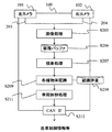
- FIG. 2 is a diagram showing a processing flow of the stereo camera 100 according to one embodiment of the present invention.
- an image is captured by the left and right cameras 101 and 102 in the in-vehicle stereo camera device 100, and the image data 203 and 204 captured by each of the left and right cameras 101 and 102 absorb the peculiar habit of the image sensor.
- Image processing such as correction for correction is performed.
- the processing result of the image processing step S205 is stored in the storage unit 106 in the image buffer step S206.
- the image buffer is provided in the storage unit 106 shown in FIG. Further, the two images corrected by the image processing unit 104 (corrected images of the images from the cameras 101 and 102) are used to compare the images, and thereby the parallax between the images obtained by the left and right cameras 101 and 102 is obtained. Information is obtained (parallax processing step S207).
- the image processing step S205, the image buffer step S206, and the parallax processing step S207 are performed by the image processing unit 104 illustrated in FIG. 1, and the finally obtained image and the parallax information are stored in the storage unit 106.
- step S209 various object recognition processes (step S209) are performed using the stored image and the parallax information.
- the object to be recognized includes a person, a car, other three-dimensional objects, a sign, a traffic light, a tail lamp, and the like.
- a recognition dictionary use step S210 (stored in the storage unit 106) is performed as necessary. Use.
- the recognition dictionary is stored in the storage unit 106.
- a warning is issued to the occupant by the vehicle control processing step S211 to control the braking and steering angle of the own vehicle. Is determined, or a policy for performing the avoidance control of the object is determined, and the result is output through the CAN interface 107 (CAN @ IF step S212).
- the various object recognition processing 209, the recognition dictionary use step S210, and the vehicle control processing step S211 are performed by the arithmetic processing unit 105 shown in FIG. 1, and the output to the in-vehicle network CAN 110 is performed by the CAN interface 107.
- Each of these processes and each means is configured by, for example, a single or a plurality of computer units, and is configured to be able to exchange data mutually.
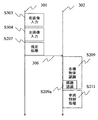
- FIG. 3 is a diagram showing a timing chart of processing in the stereo camera device.
- processing flow of two systems is shown as a processing flow 301 and a processing flow 302.
- the processing flow 301 is the processing timing in the image processing unit 104 shown in FIG. 1, and the processing flow 302 is the processing timing in the arithmetic processing unit 105 shown in FIG.
- a right image input step S303 is performed in the processing flow 301. This corresponds to the processing of capturing an image by the right camera 102 in FIG. 2, passing through the image processing 205 and storing the right image in the image buffer step S206.
- a left image input step S304 is performed. This corresponds to the processing from capturing an image by the left camera 101 in FIG. 2, through the image processing step S205, and storing the left image in the image buffer step S206.
- the parallax processing step S207 is performed. This is because, in FIG. 2, in the image buffer processing step S206, the two images from the left and right cameras 101 and 102 are read, the disparity is calculated by comparing the two images, and the calculated disparity is obtained. This corresponds to processing until information is stored in the storage unit 106. At this point, the image and the parallax information are stored in the storage unit 106. In the processing flow 301, input processing to the image buffer step S206 is performed following the parallax processing step S207.
- the processing information 306 up to the parallax processing step S207 of the processing flow 301 moves to the processing flow 302, and various object recognition 209 is performed.
- the various object recognition step S209 includes a later-described sign recognition step S209a.
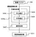
- FIG. 4A, 4B, 4C, and 4D are schematic explanatory diagrams of a marker recognition function for performing marker recognition on an image stored in the image buffer 206
- FIG. 4D is an overall schematic diagram of the marker recognition processing in the marker recognition step S209a. Shows the flow.
- the sign recognition step S209a shown in FIG. 3 includes a circle detection processing step S406 and an identification processing step S407.
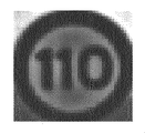
- FIG. 4A is a view showing a part of the image stored in the image buffer step S206 after the image processing step S205.
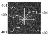
- FIG. 4B is a diagram illustrating a processing result obtained by performing image processing on the image illustrated in FIG. 4A for use in the sign recognition step S209a, and is an image having luminance in a portion where the density change is large in the vicinity of the image.
- FIG. 4C is a diagram showing a histogram obtained based on the change in shading of the image shown in FIG. 4B.
- a circle and a circle detection processing step S406 for estimating a circle and the center of the circle are performed from the image shown in FIG. 4B (images captured by the cameras 101 and 102).
- the center of the circle is obtained by “center calculation”.
- the circle detection processing step S406 is divided into center estimation (step S408) and radius estimation (step S409). Details of the radius estimation step S409 will be described later with reference to FIG.
- step S408 the center is estimated.
- a line segment 404 extending in the normal direction is drawn from each edge of the image shown in FIG. 4B, and a point where the intersections of the plurality of line segments 404 overlap by a certain number or more is estimated as the center.
- 400 is estimated as the center.
- step S409 the radius of the circle 401 (first edge) is estimated based on the histogram described in FIG. 4C. Then, identification processing of the sign detected in the identification processing step S407 (identification (recognition) of the contents of the sign) is performed, and vehicle control processing step S211 is executed.
- the horizontal axis indicates the radius from the center 400 shown in FIG. 4B, and the vertical axis indicates the number of edges within a predetermined width (within the radial width). A method of obtaining the histogram of FIG. 4C will be described.
- the number of edges 405 of the histogram shown in FIG. 4C increases, and in a case where there is no circle as in 403 shown in FIG.
- the number of edges 406 decreases.
- a histogram exceeding the predetermined edge number threshold value 407 is selected as a radius candidate.
- the counting of the number of edges may be omitted from the center 400 to a predetermined radius.
- a calculation omission area may be set.
- the calculation load on the sign recognition unit 209a can be reduced. That is, in a circle having a radius smaller than the predetermined width, it is possible to configure so as not to recognize the sign based on the change in shading.
- the calculation omission area may be reduced.
- FIG. 5 is a diagram showing a more detailed processing flow of the present invention, and shows details of the radius estimation step S409 of the flow shown in FIG. 4D.
- the separation of the random pattern is performed in the radius estimation step S409.
- the histogram creation step S500 the histogram shown in FIG. 4C is created (creation of a histogram including the number of edges and the radius that is the distance from the center of the circle to the edge).
- radius candidates are determined from the histogram created in step S500 by using a predetermined edge number threshold value 407.
- the gradient of the histogram is calculated in the histogram gradient calculation step S502 from the obtained radius candidates and the values of the histogram in the vicinity thereof.
- the random pattern separation step S503 a random pattern is separated by comparing the gradient obtained in the histogram gradient calculation step S502 with a predetermined gradient threshold.
- step S407 identification processing of the detected sign (identification (recognition) of the sign) is performed.
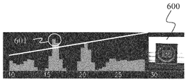
- FIGS. 6A, 6B, 6C, and 6D are diagrams for explaining that a label pattern and a random pattern are separated by a gradient of a histogram.
- FIG. 6A is a diagram showing a histogram created from an image of the sign 600.
- FIG. 6A the radius candidate estimated for the marker 600 is 601.
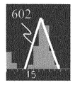
- FIG. 6B is a diagram showing the vicinity of the radius candidate 601 in the histogram shown in FIG. 6A.
- the gradient 602 of the radius candidate 601 is calculated in the histogram gradient calculation step S502.
- the gradient there are slopes on both sides of the vertex of the radius candidate 601. The slope of the slope on both sides is calculated, and the larger slope is set as the slope 602 of the radius candidate 601.
- the gradient 602 shown in FIG. 6B is equal to or greater than the gradient threshold, it is identified as a histogram indicating a sign. Since the example illustrated in FIG. 6B is a histogram indicating a marker, the gradient 602 is equal to or greater than the gradient threshold, and is identified as a histogram indicating a marker (step S503).
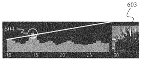
- FIG. 6C is a diagram showing a histogram created from a part 603 of a tree determined to be a circle in the circle detection processing step S406 although it is not a sign.
- the radius candidate estimated for the tree branch 603 is 604.
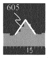
- FIG. 6D is a diagram showing the vicinity of the radius candidate 604 in the histogram shown in FIG. 6C.
- the gradient 605 of the radius candidate 604 is calculated in the histogram gradient calculation step S502.
- the gradient 605 is less than the gradient threshold, is identified as a random pattern, and is separated from the marker (step S503).
- the marker 600 and the random pattern 603 such as a tree branch can be separated.
- a circle detection process is performed on an image captured by the camera (101, 102), a histogram is created, and the number of edges within a predetermined width exceeds a predetermined edge threshold.
- the gradient is calculated as a radius candidate, and the gradient of the histogram is calculated from the radius candidate and the values of the histograms in the vicinity thereof.
- a random pattern such as a tree branch is excluded, a false determination of the random pattern as a sign is suppressed, and a sign recognition method and a sign recognition device of a camera device capable of improving sign recognition accuracy are provided. Can be realized.
- the center of the circular portion (circle) is estimated, and the radius estimation processing step S409 is performed.
- an angle image or intensity within a predetermined width is determined based on a position radially separated from the estimated center.
- create a histogram formed from the radius and the number of edges calculate the gradient of the histogram, perform the identification process for the calculated gradient is more than a predetermined gradient threshold, It can also be configured to recognize the sign.
- a histogram candidate exceeding a predetermined edge number threshold is determined as a radius candidate, a gradient of the histogram is calculated from the radius candidate and values of the histogram in the vicinity thereof, and the calculated gradient is compared with the gradient threshold to separate the random pattern. It can also be configured to do so.
- the histogram formed from the radius and the number of edges is created based on the change in the density of both the angle image and the intensity image.
- the above-described example is an example in which the sign recognition method and apparatus of the camera device of the present invention are mounted on a vehicle.
- the present invention is not limited to a vehicle, but is applied to other moving objects and robots. be able to.
Landscapes
- Engineering & Computer Science (AREA)
- Computer Vision & Pattern Recognition (AREA)
- Physics & Mathematics (AREA)
- General Physics & Mathematics (AREA)
- Theoretical Computer Science (AREA)
- Image Analysis (AREA)
- Traffic Control Systems (AREA)
Abstract
Priority Applications (3)
| Application Number | Priority Date | Filing Date | Title |
|---|---|---|---|
| EP19830290.3A EP3819866B1 (fr) | 2018-07-03 | 2019-06-05 | Procédé de reconnaissance de marqueur pour dispositif de caméra, et dispositif de reconnaissance de marqueur |
| JP2020528735A JP7005762B2 (ja) | 2018-07-03 | 2019-06-05 | カメラ装置の標識認識方法及び標識認識装置 |
| CN201980041939.3A CN112334944B (zh) | 2018-07-03 | 2019-06-05 | 摄像机装置的标志识别方法及标志识别装置 |
Applications Claiming Priority (2)
| Application Number | Priority Date | Filing Date | Title |
|---|---|---|---|
| JP2018127092 | 2018-07-03 | ||
| JP2018-127092 | 2018-07-03 |
Publications (1)
| Publication Number | Publication Date |
|---|---|
| WO2020008787A1 true WO2020008787A1 (fr) | 2020-01-09 |
Family
ID=69060930
Family Applications (1)
| Application Number | Title | Priority Date | Filing Date |
|---|---|---|---|
| PCT/JP2019/022269 Ceased WO2020008787A1 (fr) | 2018-07-03 | 2019-06-05 | Procédé de reconnaissance de marqueur pour dispositif de caméra, et dispositif de reconnaissance de marqueur |
Country Status (4)
| Country | Link |
|---|---|
| EP (1) | EP3819866B1 (fr) |
| JP (1) | JP7005762B2 (fr) |
| CN (1) | CN112334944B (fr) |
| WO (1) | WO2020008787A1 (fr) |
Citations (3)
| Publication number | Priority date | Publication date | Assignee | Title |
|---|---|---|---|---|
| JP2015191621A (ja) | 2014-03-28 | 2015-11-02 | 富士重工業株式会社 | 車外環境認識装置 |
| CN105203045A (zh) * | 2015-07-02 | 2015-12-30 | 天津师范大学 | 一种基于异步时域视觉传感器的产品形状完整性检测系统及检查方法 |
| JP2016103215A (ja) * | 2014-11-28 | 2016-06-02 | 本田技研工業株式会社 | 画像解析装置、画像特徴情報データベース作成方法並びに意匠類否判定装置及び方法 |
Family Cites Families (4)
| Publication number | Priority date | Publication date | Assignee | Title |
|---|---|---|---|---|
| KR20110104243A (ko) * | 2010-03-16 | 2011-09-22 | 에스케이텔레콤 주식회사 | 증강 현실에서 차폐된 마커의 인식 장치 및 방법 |
| KR101596299B1 (ko) * | 2014-01-06 | 2016-02-22 | 현대모비스 주식회사 | 교통 표지판 인식 방법 및 장치 |
| JP5961207B2 (ja) * | 2014-03-28 | 2016-08-02 | 富士重工業株式会社 | 車外環境認識装置 |
| CN107346413A (zh) * | 2017-05-16 | 2017-11-14 | 北京建筑大学 | 一种街景影像中的交通标志识别方法和系统 |
-
2019
- 2019-06-05 CN CN201980041939.3A patent/CN112334944B/zh active Active
- 2019-06-05 EP EP19830290.3A patent/EP3819866B1/fr active Active
- 2019-06-05 JP JP2020528735A patent/JP7005762B2/ja active Active
- 2019-06-05 WO PCT/JP2019/022269 patent/WO2020008787A1/fr not_active Ceased
Patent Citations (3)
| Publication number | Priority date | Publication date | Assignee | Title |
|---|---|---|---|---|
| JP2015191621A (ja) | 2014-03-28 | 2015-11-02 | 富士重工業株式会社 | 車外環境認識装置 |
| JP2016103215A (ja) * | 2014-11-28 | 2016-06-02 | 本田技研工業株式会社 | 画像解析装置、画像特徴情報データベース作成方法並びに意匠類否判定装置及び方法 |
| CN105203045A (zh) * | 2015-07-02 | 2015-12-30 | 天津师范大学 | 一种基于异步时域视觉传感器的产品形状完整性检测系统及检查方法 |
Non-Patent Citations (1)
| Title |
|---|
| INOUE, YASUO ET AL.: "Automatic Recognition of Road Signs", PROC. OF SPIE, vol. 4790, 2002, pages 543 - 550, XP055763208 * |
Also Published As
| Publication number | Publication date |
|---|---|
| EP3819866A4 (fr) | 2022-04-06 |
| CN112334944A (zh) | 2021-02-05 |
| JP7005762B2 (ja) | 2022-02-10 |
| CN112334944B (zh) | 2023-09-08 |
| JPWO2020008787A1 (ja) | 2021-04-30 |
| EP3819866A1 (fr) | 2021-05-12 |
| EP3819866B1 (fr) | 2025-04-09 |
Similar Documents
| Publication | Publication Date | Title |
|---|---|---|
| CN112292711B (zh) | 关联lidar数据和图像数据 | |
| EP4060640B1 (fr) | Procédé de reconnaissance de signal de trafic et dispositif de reconnaissance de signal de trafic | |
| JP7040374B2 (ja) | 物体検出装置、車両制御システム、物体検出方法及び物体検出用コンピュータプログラム | |
| US10672141B2 (en) | Device, method, system and computer-readable medium for determining collision target object rejection | |
| EP3545464B1 (fr) | Dispositif de traitement d'informations, dispositif d'imagerie, système de commande d'équipement, objet mobile, procédé de traitement d'informations et support d'enregistrement lisible par ordinateur | |
| CN107667378B (zh) | 用于识别和评估路面反射的方法和装置 | |
| JP6457278B2 (ja) | 物体検出装置及び物体検出方法 | |
| JP6283105B2 (ja) | ステレオカメラ装置、ステレオカメラ装置を設置した車両及びプログラム | |
| US10748014B2 (en) | Processing device, object recognition apparatus, device control system, processing method, and computer-readable recording medium | |
| CN107408288B (zh) | 警告装置、警告方法以及警告程序 | |
| CN102842038A (zh) | 环境识别装置及环境识别方法 | |
| JP7095559B2 (ja) | 区画線検出装置及び区画線検出方法 | |
| CN113569812A (zh) | 未知障碍物的识别方法、装置和电子设备 | |
| JP6174884B2 (ja) | 車外環境認識装置および車外環境認識方法 | |
| JP2018073049A (ja) | 画像認識装置、画像認識システム、及び画像認識方法 | |
| JP6569416B2 (ja) | 画像処理装置、物体認識装置、機器制御システム、画像処理方法及び画像処理プログラム | |
| WO2020008787A1 (fr) | Procédé de reconnaissance de marqueur pour dispositif de caméra, et dispositif de reconnaissance de marqueur | |
| JP2013161433A (ja) | 車両の周辺監視装置 | |
| EP4258243A1 (fr) | Dispositif de traitement d'image, procédé de traitement d'image et programme | |
| JP7064400B2 (ja) | 物体検知装置 | |
| JP2018088237A (ja) | 情報処理装置、撮像装置、機器制御システム、移動体、情報処理方法、及び、情報処理プログラム | |
| JP2017211765A (ja) | 物体認識装置 | |
| WO2020071132A1 (fr) | Dispositif de caméra | |
| CN118587244B (zh) | 车辆轨迹预测方法、装置、电子设备及存储介质 | |
| JP7446445B2 (ja) | 画像処理装置、画像処理方法、及び車載電子制御装置 |
Legal Events
| Date | Code | Title | Description |
|---|---|---|---|
| 121 | Ep: the epo has been informed by wipo that ep was designated in this application |
Ref document number: 19830290 Country of ref document: EP Kind code of ref document: A1 |
|
| ENP | Entry into the national phase |
Ref document number: 2020528735 Country of ref document: JP Kind code of ref document: A |
|
| NENP | Non-entry into the national phase |
Ref country code: DE |
|
| ENP | Entry into the national phase |
Ref document number: 2019830290 Country of ref document: EP Effective date: 20210203 |
|
| WWG | Wipo information: grant in national office |
Ref document number: 2019830290 Country of ref document: EP |