WO2020008831A1 - 基板熱処理装置及び基板熱処理方法 - Google Patents
基板熱処理装置及び基板熱処理方法 Download PDFInfo
- Publication number
- WO2020008831A1 WO2020008831A1 PCT/JP2019/023477 JP2019023477W WO2020008831A1 WO 2020008831 A1 WO2020008831 A1 WO 2020008831A1 JP 2019023477 W JP2019023477 W JP 2019023477W WO 2020008831 A1 WO2020008831 A1 WO 2020008831A1
- Authority
- WO
- WIPO (PCT)
- Prior art keywords
- substrate
- heat treatment
- exhaust
- treatment apparatus
- substrate heat
- Prior art date
- Legal status (The legal status is an assumption and is not a legal conclusion. Google has not performed a legal analysis and makes no representation as to the accuracy of the status listed.)
- Ceased
Links
Images



Classifications
-
- H—ELECTRICITY
- H10—SEMICONDUCTOR DEVICES; ELECTRIC SOLID-STATE DEVICES NOT OTHERWISE PROVIDED FOR
- H10P—GENERIC PROCESSES OR APPARATUS FOR THE MANUFACTURE OR TREATMENT OF DEVICES COVERED BY CLASS H10
- H10P52/00—Grinding, lapping or polishing of wafers, substrates or parts of devices
-
- H—ELECTRICITY
- H10—SEMICONDUCTOR DEVICES; ELECTRIC SOLID-STATE DEVICES NOT OTHERWISE PROVIDED FOR
- H10P—GENERIC PROCESSES OR APPARATUS FOR THE MANUFACTURE OR TREATMENT OF DEVICES COVERED BY CLASS H10
- H10P76/00—Manufacture or treatment of masks on semiconductor bodies, e.g. by lithography or photolithography
Definitions
- the present invention relates to semiconductor wafers, liquid crystal display substrates, plasma display substrates, organic EL substrates, FED (Field Emission Display) substrates, optical display substrates, magnetic disk substrates, magneto-optical disk substrates, and photomasks.
- the present invention relates to a substrate heat treatment apparatus and a substrate heat treatment method for performing heat treatment on various substrates (hereinafter, simply referred to as substrates) such as a substrate and a solar cell substrate.
- a heating plate that heats a substrate placed on the upper surface, an inert gas supply chamber that is disposed above the heating plate, and supplies an inert gas to the substrate, a heating plate
- Some include a housing surrounding the inert gas supply chamber and an exhaust port formed at a position above the outer peripheral edge of the substrate (for example, see Patent Document 1). Further, some include an inert gas supply chamber that is disposed above the heating plate and has a plurality of inert gas blowing holes, and a plurality of exhaust ports formed around the heating plate.
- an inert gas is supplied to the substrate from the inert gas supply chamber, and the substrate is heated by a heating plate while purging the gas in the housing.
- a strong underlayer film is formed by a multi-layer resist process for fine processing.
- a treatment liquid for an underlayer film is applied to a substrate to form a coating film, and then the substrate is baked at a high temperature such as 300 ° C.
- the substrate is baked at a high temperature such as 300 ° C.
- the conventional example having such a configuration has the following problem. That is, in the conventional apparatus, since the flow of the inert gas is relatively long from the discharge port on the outer peripheral edge of the substrate, the flow of the inert gas on the surface of the substrate is likely to be unstable, and The air flow of the active gas is likely to be uneven. Therefore, there is a problem that the coating film is affected by the influence and the uniformity of the thickness of the lower film after the heat treatment is deteriorated.
- the above-mentioned problem is remarkable in the case of an underlayer film that generates a sublimate. For example, even if a coating film made of a photoresist solution is heated at about 120 to 160 ° C., the solvent is removed from the coating film. Similar problems can arise because the containing gas is purged with an inert gas.
- the present invention has been made in view of such circumstances, and an object of the present invention is to provide a substrate heat treatment apparatus and a substrate heat treatment method capable of improving film thickness uniformity by devising gas discharge.
- the invention has the following configuration to achieve such an object. That is, the invention according to claim 1 includes a heating plate for mounting the substrate and heating the substrate, a housing surrounding the heating plate to form a processing atmosphere, and the housing being formed on the housing, An outlet for discharging a gas in the processing atmosphere to the outside of the housing; an inert gas supply unit disposed above the heating plate, for supplying an inert gas to the processing atmosphere; Exhaust means for exhausting the gas of the processing atmosphere from the exhaust port, the exhaust means comprising a plurality of exhaust ports dispersedly arranged on the entire surface of the substrate in plan view. It is characterized by having.
- the exhaust means is provided with a plurality of exhaust ports, the gas in the processing atmosphere is exhausted from places dispersed in the entire surface of the substrate in plan view. Therefore, the distance from the inert gas supply means to any of the exhaust ports can be made shorter than before, so that the flow of the inert gas on the surface of the substrate is stabilized, and the unevenness of the flow of the inert gas can be suppressed. Therefore, the coating film is not adversely affected and the uniformity of the film thickness can be improved.
- the plurality of exhaust ports are configured to collect gas at an collecting portion and exhaust the gas to the outlet, and are arranged concentrically around the collecting portion in plan view. (Claim 2).
- the plurality of exhaust ports have an inner diameter of an exhaust port far from a central portion larger than an inner diameter of an exhaust port near a central portion (claim 3).
- the exhaust gas can be exhausted smoothly from all the exhaust ports and can be exhausted uniformly over the entire surface of the substrate.
- a supply / discharge unit in which the inert gas supply means and the exhaust means are integrally formed, and the supply / discharge unit comprises a plurality of blowouts for supplying an inert gas over the entire surface of the substrate.
- a first diffusion plate having holes formed therein, a cylindrical shape having a closed ceiling surface, an inner diameter larger than an outer diameter of the heating plate, and an outer cover exhaust port connected to the outlet and formed.
- An outer cover having a cylindrical shape with a closed ceiling surface, having an outer diameter smaller than the inner diameter of the outer cover, and having an inner diameter larger than the outer diameter of the substrate, and an inner periphery of the outer cover.
- the inert gas supply means and the exhaust means are integrally formed as a supply / discharge unit, the size of the apparatus can be reduced. Further, since the inert gas is supplied from the plurality of blowout holes of the first diffusion plate over the entire surface of the substrate, purging in the processing atmosphere over the entire surface of the substrate can be efficiently performed.
- the plurality of exhaust ports are a plurality of exhaust ducts
- the lower surface of the first diffusion plate provided inside the outer cover is connected to the upper surface of the exhaust cover
- the upper surface of the exhaust cover is Gas can be exhausted to the outer cover exhaust port and the exhaust port through the gap between the outer cover and the ceiling surface, and the gas of the processing atmosphere is exhausted from the outer peripheral edge of the substrate through the gap between the inner peripheral surface of the outer cover and the outer peripheral surface of the exhaust cover. . Therefore, since the gas is exhausted from the entire surface and the outer peripheral edge of the substrate, the gas in the processing atmosphere can be efficiently exhausted.
- the first diffuser plate has a layout density of the plurality of blowout holes in a region corresponding to the inlet in plan view, and the plurality of blowout holes in a region other than the region corresponding to the inlet. It is preferable that the density is lower than the arrangement density of the blowing holes.
- the inert gas supplied to the substrate through the first diffusion plate has a high pressure in the plurality of blowout holes in a region corresponding to the inlet, and the supply amount is likely to increase. Therefore, in the region corresponding to the inlet, the arrangement density of the plurality of blowout holes is reduced to balance the supply of the inert gas in the region corresponding to the inlet and the other region. Therefore, the inert gas can be uniformly supplied over the entire surface of the substrate.
- the supply / discharge unit includes a second diffusion plate having a plurality of blowout holes for supplying an inert gas over the entire surface of the substrate below the first diffusion plate. (Claim 6).
- the inert gas is supplied in a double structure of the first diffusion plate and the second diffusion plate, the supply of the inert gas can be moderated. Therefore, an adverse effect on the coating film due to the supply of the inert gas can be suppressed.
- the plurality of outlets of the first diffuser have a smaller diameter than the plurality of outlets of the second diffuser.
- the first diffusion plate has a spacer on an upper surface thereof, which is in contact with a ceiling surface of the exhaust cover (claim 8).
- the second diffusion plate has a spacer on an upper surface thereof that penetrates the first diffusion plate and contacts a ceiling surface of the exhaust cover (claim 9).
- the first diffuser plate and the second diffuser plate have different positions of the plurality of blowout holes in plan view (claim 10).
- the exhaust cover is provided with a spacer on an upper surface which is in contact with a ceiling surface of the outer cover (claim 11).
- a substrate heat treatment method for performing a heat treatment on a substrate coated with a coating film, wherein the substrate is placed on a heat treatment plate and heated to be inert to a processing atmosphere of the substrate.
- the gas in the processing atmosphere is exhausted from a plurality of locations dispersed over the entire surface of the substrate.
- the gas in the processing atmosphere is exhausted from a portion dispersed in the entire surface of the substrate in plan view. Therefore, the distance for discharging the gas over the entire surface of the substrate can be made shorter than before, so that the flow of the inert gas on the surface of the substrate is stabilized, and the unevenness of the flow of the inert gas can be suppressed. Therefore, the coating film is not adversely affected and the uniformity of the film thickness can be improved.
- the exhaust means is provided with the plurality of exhaust ports, the gas in the processing atmosphere is exhausted from a portion dispersed in the entire surface of the substrate in plan view. Therefore, the distance from the inert gas supply means to any of the exhaust ports can be made shorter than before, so that the flow of the inert gas on the surface of the substrate is stabilized, and the unevenness of the flow of the inert gas can be suppressed. Therefore, the coating film is not adversely affected and the uniformity of the film thickness can be improved.
- FIG. 3 is a plan view showing a first diffusion plate.
- FIG. 4 is a plan view showing a second diffusion plate. It is a longitudinal cross-sectional view which shows the whole structure of the substrate heat processing apparatus which concerns on a 1st modification. It is a longitudinal section showing the whole composition of the substrate heat treatment device concerning the 2nd modification.
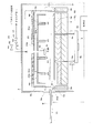
- FIG. 1 is a longitudinal sectional view showing the entire configuration of the substrate heat treatment apparatus according to the embodiment
- FIG. 2 is a perspective view of a supply / discharge unit.
- the substrate heat treatment apparatus is a single-wafer apparatus that sequentially heat-treats the substrates W one by one.
- the substrate heat treatment apparatus processes a substrate W having a surface (upper surface) coated with a coating film.
- the coating film in the present embodiment is a coating film formed by applying a treatment liquid for an underlayer film.
- This substrate heat treatment apparatus includes a heating plate 1, a housing 3, a discharge port 5, a supply / discharge unit 7, and a lifting pin unit 9.
- a transfer arm 11 for transferring the substrate W to and from the substrate heat treatment apparatus is disposed in the substrate heat treatment apparatus.
- the heating plate 1 has a circular shape in plan view.
- the heating plate 1 has a built-in heater 1a inside.
- the heater 1a heats the heating plate 1 and raises the temperature to a predetermined heat treatment temperature (for example, 200 to 400 ° C.) for processing the substrate W.
- the heating plate 1 has an annular member 1b disposed at a position separated from the outer peripheral surface thereof.
- a seal member 1c having an annular shape in plan view is attached to the upper surface of the annular member 1b.
- the elevating pin unit 9 includes three elevating pins 9a. In FIG. 1, only two lifting pins 9a are shown for the sake of illustration.
- the three elevating pins 9a are arranged corresponding to the positions of the vertices of an equilateral triangle in plan view.
- the three lifting pins 9a are connected at the base end side by a connecting member 9b.
- a lifting mechanism (not shown) raises and lowers the connecting member 9b, thereby raising and lowering the three lifting pins 9a integrally.
- the elevating position is a delivery position that has risen most and a standby position that has descended from the upper surface of the heating plate 1.
- the casing 3 surrounds the entire heating plate 1 and the annular member 1b to form a processing atmosphere pa.
- the processing atmosphere pa is formed in an upper space including the upper surface of the heating plate 1.
- the housing 3 has an outlet 5 formed therein. Specifically, the outlet 5 is formed, for example, at the center of the upper surface of the housing 3 in plan view.
- the discharge port 5 discharges the gas in the processing atmosphere pa to the outside of the housing 3.
- the discharge port 5 discharges gas via an exhaust pipe 15 connected to the exhaust processing unit.
- the discharge pipe 15 is provided with an on-off valve V1.
- the on-off valve V1 shuts off or allows the flow of gas in the discharge pipe 15.
- the casing 3 has a carry-in / out port 3a formed on the left side in FIG.
- the loading / unloading port 3 a is used for transferring the substrate W between the substrate heat treatment apparatus and the transfer arm 11.
- a shutter (not shown) is arranged at the loading / unloading port 3a. The loading / unloading port 3a is closed during the heat treatment, and is opened when the substrate W is transferred.
- the supply / discharge unit 7 supplies an inert gas (for example, nitrogen gas) to the processing atmosphere pa and discharges the gas of the processing atmosphere pa from the discharge port 5 to the outside.
- the supply / discharge unit 7 is arranged between the housing 3 and the heating plate 1. Since the apparatus of this embodiment is configured so that the supply and exhaust of the inert gas is performed by the supply / discharge unit 7, the size of the apparatus can be reduced.
- the supply / discharge unit 7 includes an outer cover 21, an exhaust cover 23, a first diffusion plate 25, and a second diffusion plate 27.
- the outer cover 21 moves up and down between a processing position (height position shown in FIG. 1) in the housing 3 and a carry-in / out position (height position shown by a two-dot chain line in FIG. 1) that has risen in the housing 3. (Not shown).
- the outer cover 21 has a cylindrical shape in which the ceiling surface is closed, and a flange 21a extending in the outer peripheral direction is formed at the lower end of the outer peripheral surface.
- the outer cover 21 has an outer cover exhaust port 21b formed at the center in plan view.
- the lower surface of the flange 21a contacts the seal member 1c when the outer cover 21 is moved to the processing position, and the processing atmosphere pa is closed by the outer cover 21 from the surroundings.
- the outer cover outlet 21b is connected to the outlet 5 in communication.
- An upper heater 21c is attached to the upper surface of the outer cover 21. The upper heater 21c prevents the sublimate from accumulating on the outer cover 21 when exhausting the gas containing the sublimate. The upper heater 21c raises the temperature of an inert gas described later.
- the exhaust cover 23 is attached inside the outer cover 21.
- the exhaust cover 23 has a cylindrical shape with a ceiling surface closed.
- the exhaust cover 23 has a cylindrical height lower than that of the outer cover 21 and an outer diameter smaller than the inner diameter of the outer cover 21, and has a size that is completely accommodated in the outer cover 21.
- the exhaust cover 23 has a plurality of bosses 23a and one inlet 23b formed on the upper surface.
- the upper surface of the exhaust cover 23 is separated from the ceiling surface of the outer cover 21 by a predetermined distance by a plurality of bosses 23a, and is attached with a gap provided.
- the introduction port 23b of the exhaust cover 23 has an upper end protruding upward through the upper surface of the outer cover 21.
- the outer surface and the upper surface of the exhaust cover 23 and the inner surface and the ceiling surface of the outer cover 21 constitute an exhaust path ep.
- the exhaust path ep is gathered at an outer cover exhaust port 21b which is a gathering portion, and gas flowing through the exhaust path ep is exhausted from the outer cover exhaust port 21b.
- the boss 23a can maintain a constant gap between the ceiling surface of the outer cover 21 and the upper surface of the exhaust cover 23, thereby preventing the exhaust cover 23 from being tilted in the outer cover 21 due to vibration during assembly or operation. it can. Therefore, it is possible to prevent the exhaust from being uneven over the entire surface of the substrate W due to the inclination of the exhaust cover 23.
- One end of the supply pipe 24 is connected to the inlet 23b.
- the other end of the supply pipe 24 is connected to an inert gas supply source.
- the supply pipe 24 is provided with an on-off valve V2.
- the on-off valve V2 controls the flow of gas in the supply pipe 24.
- a first diffusion plate 25 is mounted inside the exhaust cover 23.
- the first diffusion plate 25 is attached with the upper surface separated from the ceiling surface of the exhaust cover 23 by a predetermined distance below.
- a second diffusion plate 27 is attached to the lower end surface of the exhaust cover 23, that is, below the first diffusion plate 25, while being separated from the first diffusion plate 25 by a predetermined distance.
- the distance between the upper surface of the first diffuser plate 25 and the ceiling surface of the exhaust cover 23 and the distance between the lower surface of the first diffuser plate 25 and the upper surface of the second diffuser plate 27 are the same. Is set.
- FIG. 3 is a plan view showing the first diffusion plate
- FIG. 4 is a plan view showing the second diffusion plate.
- the first diffusion plate 25 has a plurality of blowout holes 25a dispersed over the entire surface.
- Each blowout hole 25a has a diameter d1 (for example, 1 mm).
- Each blowout hole 25a is formed such that the arrangement density in a region corresponding to the inlet 23b is lower than the arrangement density in a region other than the region corresponding to the inlet 23b.
- 21 first exhaust openings 25b are formed concentrically in a plan view at positions that do not overlap with the blowout holes 25a. Specifically, three first exhaust openings 25b are formed on the center side around the outer cover exhaust port 21b, and six first exhaust openings 25b are formed on the outer peripheral side thereof. Twelve first exhaust openings 25b are formed on the outer peripheral side.
- the 21 first exhaust openings 25b formed in the first diffusion plate 25 are set such that the inner diameter of the first exhaust opening 25b far from the center is larger than the inner diameter of the first exhaust opening 25b near the center.
- the inert gas supplied through the first diffusion plate 25 has a high pressure in the plurality of blowout holes 25a in a region corresponding to the inlet 23b, and the supply amount is likely to increase. Therefore, in the region corresponding to the inlet 23b, the arrangement density of the plurality of blow-out holes 25a is reduced to balance the supply of the inert gas in the region corresponding to the inlet 23b and the rest. Therefore, the inert gas can be evenly supplied.
- the first diffusion plate 25 has six bosses 25c (hatched circles in FIG. 3) and six through-holes 25d (black circles in FIG. 3). .
- the six bosses 25c are divided into three bosses 25c on the center side and three bosses 25c on the outer side.
- the three bosses 25c on the center side are provided at the positions of the vertices of an equilateral triangle in plan view, and the three bosses 25c outside the boss 25c face the sides connecting the three inner bosses 25c. It is provided in.
- the first diffusion plate 25 is attached to the exhaust cover 23 by six bosses 25c.
- the second diffusion plate 27 has a plurality of blowout holes 27a formed over the entire surface in plan view.
- Each outlet hole 27a has a diameter d2 (for example, 2 mm) larger than the diameter d1 of the outlet hole d25a.
- each blowout hole 27a is formed so as to be in a position that does not overlap with the position of each blowout hole 25a of the first diffusion plate 25 in plan view (a positional relationship that does not match in plan view).
- 21 second exhaust openings 27b are formed concentrically in plan view at positions that do not overlap with the blowout holes 27a. Specifically, three second exhaust openings 27b are formed on the center side around the outer cover exhaust port 21b, and six second exhaust openings 27b are formed on the outer peripheral side thereof.
- the 21 second exhaust openings 27b formed in the second diffusion plate 27 are formed at positions corresponding to the first exhaust openings 25b formed in the first diffusion plate 25 in plan view, Similarly, the inner diameter of the one far from the center is set larger than the inner diameter of the one near the center.
- the second diffusion plate 27 has six bosses 27c (hatched circles in FIG. 4).
- the six bosses 27c are formed at positions corresponding to the six through-holes 25d (black circles in FIG. 3) formed in the first diffusion plate 25 described above.
- the first diffusion plate 25 and the second diffusion plate 27 are connected so that the first exhaust opening 25 b and the second exhaust opening 27 b are connected by an exhaust duct 29.
- the plurality of exhaust ducts 29 concentrically with the outer cover exhaust port 21b as the center in plan view, the distance to the exhaust on the entire surface of the substrate W can be conventionally reduced at any position on the surface of the substrate W. Can be shorter in comparison.
- the exhaust duct 29 has an inner diameter farther from the center portion set to be larger than an inner diameter near the center portion. Since the amount of the inert gas exhausted farther from the central portion is larger than that of the central portion, the exhaust gas can be exhausted smoothly from all the exhaust ducts 29 and can be exhausted uniformly over the entire surface of the substrate W.
- the boss 23a, the boss 25c, and the boss 27c correspond to the "spacer” in the present invention.
- the supply / discharge unit 7 and the exhaust duct 29 correspond to “exhaust means” in the present invention
- the first exhaust opening 25b, the second exhaust opening 27b, and the exhaust duct 29 are “exhaust ports” in the present invention.
- the supply / discharge unit 7, the first diffusion plate 25, and the second diffusion plate 27 correspond to "inert gas supply means" in the present invention.
- the control unit 31 controls the movement of the transfer arm 11, the lifting and lowering of the lifting and lowering pin unit 9, the lifting and lowering of the supply / discharge unit 7, and the opening and closing of the on-off valves V1 and V2.
- the control unit 31 includes a CPU and a memory, and operates each unit according to a recipe that defines processing conditions for the heat treatment.
- heat treatment is performed on the substrate W on which the coating film is applied as follows.
- the on-off valves V1 and V2 are always open, and the inert gas is constantly supplied from the supply / discharge unit 7 to the processing atmosphere pa, and the gas in the processing atmosphere pa is constantly exhausted. Further, the control unit 31 previously controls the temperature of the heating plate 1 to a processing temperature (for example, 300 ° C.) by the heater 1a.
- the control unit 31 raises the outer cover 21 together with the supply / discharge unit 7 to the carry-in / out position, and moves a shutter (not shown) to open the carry-in / out port 3a.
- the lifting / lowering pin unit 9 is operated to move the lifting / lowering pins 9a to the transfer position, the transport arm 11 holding the substrate W to be processed is advanced into the processing atmosphere pa, and the substrate W is placed on the lifting / lowering pins 9a.
- the transfer arm 11 is moved out of the loading / unloading port 3a.
- the elevating pin unit 9 is operated to move the elevating pin 9a to the standby position and lower the outer cover 21 and the supply / discharge unit 7 to the processing position.
- the substrate W is placed on the heating plate 1 and the heat treatment is started.
- the inert gas is supplied from the supply / discharge unit 7 to the surface of the substrate W, and the gas in the processing atmosphere pa is discharged.
- a coating film for forming a lower layer film is applied to the surface of the substrate W, since the inert gas is moderated by the first diffusion plate 25 and the second diffusion plate 27, the coating is performed. The coating is not easily affected.
- sublimates are generated from the coating film and are exhausted along with the flow of the inert gas. The exhaust is performed by a plurality of exhaust ducts 29.
- the gas of the processing atmosphere pa is exhausted from a portion dispersed over the entire surface of the substrate W in a plan view. Therefore, the distance from the inert gas supplied to the processing atmosphere pa to any of the exhaust ducts 29 can be made shorter than before, so that the flow of the inert gas on the surface of the substrate W is stabilized, and Air flow unevenness can be suppressed. Therefore, the coating film is not adversely affected and the uniformity of the film thickness can be improved.
- the supply / discharge unit 7 supplies the inert gas from the plurality of blowing holes 25a of the first diffusion plate 25 over the entire surface of the substrate W, the purging in the processing atmosphere pa over the entire surface of the substrate W can be efficiently performed.
- the plurality of exhaust ducts 29 can exhaust air to the outer cover exhaust port 21 b and the exhaust port 5 through an exhaust path ep provided inside the outer cover 21.
- the gas of the processing atmosphere pa is exhausted from the outer peripheral edge of the substrate W through a gap with the outer peripheral surface. Therefore, since the gas is exhausted from the entire surface and the outer peripheral edge of the substrate W, the gas in the processing atmosphere pa can be efficiently exhausted.
- the supply / discharge unit 7 supplies the inert gas with the double structure of the first diffusion plate 25 and the second diffusion plate 27, the supply of the inert gas can be moderated. Therefore, an adverse effect on the coating film due to the supply of the inert gas can be suppressed.
- the diameter d1 of the blowout hole 25a of the first diffusion plate 25 is smaller than the diameter d2 of the blowout hole 27a of the second diffusion plate 27 (d1 ⁇ d2).
- the supply of the inert gas to the first diffusion plate 27 becomes gentle, and the supply of the inert gas from the second diffusion plate 27 to the substrate W can be further moderated. Therefore, the adverse effect on the coating film due to the supply of the inert gas can be further suppressed.
- the distance from the upper surface can be kept constant. It is possible to prevent the first diffusion plate 25 and the second diffusion plate 27 from being inclined in the exhaust cover 23 due to vibration at the time. Therefore, it is possible to prevent the supply of the inert gas to the entire surface of the substrate W from becoming uneven due to the inclination of the first diffusion plate 25 and the second diffusion plate 27.
- the present invention is not limited to the above embodiment, but can be modified as follows.
- FIG. 5 is a longitudinal sectional view showing the overall configuration of the substrate heat treatment apparatus according to the first modification.
- the exhaust unit 41 exhaust means
- the inert gas supply unit 43 inert gas supply means
- the exhaust unit 41 includes a plurality of exhaust ducts 29 distributed over the entire surface of the substrate W.
- the inert gas supply unit 43 supplies the inert gas radially from the center of the substrate W toward the outer periphery.
- FIG. 6 is a longitudinal sectional view showing the entire configuration of the substrate heat treatment apparatus according to the second modification.
- an exhaust unit 41 exhaust means
- an inert gas supply unit 43 inert gas supply means
- the supply / discharge unit 7 includes the first diffusion plate 25 and the second diffusion plate 27 in a double manner, but the present invention is not limited to such a configuration. That is, a single diffusion plate may be used. Further, the configuration may not include the diffusion plate itself.
- the coating film applied to the substrate W forms the lower layer film
- the present invention is not limited to such a coating film.
- the present invention can be applied to an apparatus that heat-treats a coating film made of a photoresist solution at about 120 to 160 ° C.
- the inner diameter increases as the distance from the center increases, but the exhaust ducts 29 are arranged with the same inner diameter of all the exhaust ducts 29.
- the number of exhaust gases may be balanced.
- the present invention is suitable for a substrate heat treatment apparatus and a substrate heat treatment method for performing heat treatment.
Landscapes
- Exposure Of Semiconductors, Excluding Electron Or Ion Beam Exposure (AREA)
- Cleaning Or Drying Semiconductors (AREA)
Abstract
複数個の排気ダクト(29)は、平面視で基板(W)の全面に分散して配置されているので、処理雰囲気(pa)の気体が平面視で基板(W)の全面に分散した箇所から排気される。したがって、処理雰囲気(pa)に供給された不活性ガスからいずれかの排気ダクト(29)までの距離が従来に比べて短くできるので、基板(W)の表面上における不活性ガスの気流が安定し、不活性ガスの気流のムラを抑制できる。したがって、塗布被膜が悪影響を受けることがなく、膜厚均一性を向上できる。
Description
本発明は、半導体ウエハ、液晶ディスプレイ用基板、プラズマディスプレイ用基板、有機EL用基板、FED(Field Emission Display)用基板、光ディスプレイ用基板、磁気ディスク用基板、光磁気ディスク用基板、フォトマスク用基板、太陽電池用基板などの各種基板(以下、単に基板と称する)に対して、熱処理を施す基板熱処理装置及び基板熱処理方法に関する。
従来、この種の装置として、上面に載置された基板を加熱する加熱プレートと、加熱プレートの上方に配置され、基板に対して不活性ガスを供給する不活性ガス供給チャンバと、加熱プレート及び不活性ガス供給チャンバを囲う筐体と、基板の外周縁の上方にあたる位置に形成された排気口とを備えたものがある(例えば、特許文献1参照)。また、加熱プレートの上方に配置され、複数個の不活性ガス吹き出し孔を有する不活性ガス供給チャンバと、加熱プレートの周囲に形成された複数個の排気口とを備えたものもある。
このように構成された装置では、不活性ガス供給チャンバから不活性ガスを基板に供給し、筐体内の気体をパージしつつ、基板を加熱プレートで加熱処理する。
最近の半導体プロセスにおいては、微細加工用の多層レジストプロセスなどで強固な下層膜を形成することが行われている。このような多層レジストプロセスにおいては、下層膜用の処理液を基板に塗布して塗布被膜を被着させた後、その基板を例えば300℃などの高温で焼成することにより、塗布被膜から下層膜を生成する。その際には、塗布被膜から昇華物が発生するので、不活性ガスにより昇華物を押し出しつつ、不活性ガスとともに昇華物を排気口から排出している。
しかしながら、このような構成を有する従来例の場合には、次のような問題がある。
すなわち、従来の装置は、不活性ガスの流れが基板の外周縁の排出口までと比較的長い距離となっているので、基板の表面上における不活性ガスの気流が不安定になりやすく、不活性ガスの気流にムラが生じやすい。したがって、塗布被膜がその影響を受け、熱処理後の下層膜における膜厚均一性が悪化するという問題がある。
すなわち、従来の装置は、不活性ガスの流れが基板の外周縁の排出口までと比較的長い距離となっているので、基板の表面上における不活性ガスの気流が不安定になりやすく、不活性ガスの気流にムラが生じやすい。したがって、塗布被膜がその影響を受け、熱処理後の下層膜における膜厚均一性が悪化するという問題がある。
なお、上述したような問題は、昇華物を生じる下層膜の場合には顕著であるが、例えば、フォトレジスト液よりなる塗布被膜を120~160℃程度で加熱しても、塗布被膜から溶剤を含むガスを不活性ガスでパージするので、同様の問題が生じ得る。
本発明は、このような事情に鑑みてなされたものであって、気体の排出を工夫することにより、膜厚均一性を向上できる基板熱処理装置及び基板熱処理方法を提供することを目的とする。
本発明は、このような目的を達成するために、次のような構成をとる。
すなわち、請求項1に記載の発明は、前記基板を載置して前記基板を加熱する加熱プレートと、前記加熱プレートを囲って処理雰囲気を形成する筐体と、前記筐体に形成され、前記処理雰囲気の気体を前記筐体の外部へと排出する排出口と、前記加熱プレートの上方に配置され、前記処理雰囲気に不活性ガスを供給する不活性ガス供給手段と、前記加熱プレートの上方に配置され、前記処理雰囲気の気体を前記排出口から排気する排気手段と、を備え、前記排気手段は、平面視にて前記基板の全面に分散して配置された複数個の排気口を備えていることを特徴とするものである。
すなわち、請求項1に記載の発明は、前記基板を載置して前記基板を加熱する加熱プレートと、前記加熱プレートを囲って処理雰囲気を形成する筐体と、前記筐体に形成され、前記処理雰囲気の気体を前記筐体の外部へと排出する排出口と、前記加熱プレートの上方に配置され、前記処理雰囲気に不活性ガスを供給する不活性ガス供給手段と、前記加熱プレートの上方に配置され、前記処理雰囲気の気体を前記排出口から排気する排気手段と、を備え、前記排気手段は、平面視にて前記基板の全面に分散して配置された複数個の排気口を備えていることを特徴とするものである。
[作用・効果]請求項1に記載の発明によれば、排気手段が複数個の排気口を備えているので、処理雰囲気の気体が平面視で基板の全面に分散した箇所から排気される。したがって、不活性ガス供給手段からいずれかの排気口までの距離が従来に比べて短くできるので、基板の表面上における不活性ガスの気流が安定し、不活性ガスの気流のムラを抑制できる。したがって、塗布被膜が悪影響を受けることがなく、膜厚均一性を向上できる。
また、本発明において、前記複数個の排気口は、気体を集合部位にて集合して前記排出口に排気する構成であって、平面視にて前記集合部位を中心とする同心円状に配置されていることが好ましい(請求項2)。
複数個の排気口を、集合部位を中心とした同心円状にすることにより、基板の表面上のどの位置においても、基板の全面において排気までの距離を従来に比較して短くできる。
また、本発明において、前記複数個の排気口は、中心部から遠い排気口の内径が、中心部に近い排気口の内径より大きいことが好ましい(請求項3)。
中心部から遠い方が排気する不活性ガスの量が中心部よりも多いので、全ての排気口から円滑に排気することができ、基板の全面において均等に排気できる。
また、本発明において、前記不活性ガス供給手段と前記排気手段とを一体的に構成した給排ユニットを備え、前記給排ユニットは、前記基板の全面にわたって不活性ガスを供給する複数個の吹き出し孔が形成された第1の拡散板と、天井面が閉塞された円筒形状を呈し、前記加熱プレートの外径より大きな内径を備え、前記排出口に連通接続された外カバー排気口を形成されている外カバーと、天井面が閉塞された円筒形状を呈し、前記外カバーの内径より小さな外径を有し、かつ、前記基板の外径より大きな内径を有し、前記外カバーの内周面と、前記外カバーの天井面との間に隙間を設けて配置され、前記隙間を前記外カバー排気口に連通接続され、前記処理雰囲気に不活性ガスを導入する導入口を備え、天井面から下方に離間して前記第1の拡散板を取り付けられた排気カバーと、を備え、前記複数個の排気口は、前記第1の拡散板の下面と前記排気カバーの上面とを連通接続している複数個の排気ダクトであることが好ましい(請求項4)。
不活性ガス供給手段と排気手段とを給排ユニットとして一体的に構成したので、装置の小型化を図ることができる。さらに、第1の拡散板の複数個の吹き出し孔から不活性ガスを基板の全面にわたって供給するので、基板の全面における処理雰囲気におけるパージを効率的にできる。また、複数個の排気口が複数個の排気ダクトであり、外カバーの内部に設けられた第1の拡散板の下面と排気カバーの上面とを連通接続しているので、排気カバーの上面と外カバーの天井面との隙間を通して外カバー排気口及び排出口に排気でき、また、外カバーの内周面と排気カバーの外周面との隙間を通して処理雰囲気の気体を基板の外周縁から排気する。したがって、基板の全面及び外周縁から排気するので、処理雰囲気の気体を効率的に排出できる。
また、本発明において、前記第1の拡散板は、平面視にて前記導入口に対応する領域における前記複数個の吹き出し孔の配置密度が、前記導入口に対応する領域以外における前記複数個の吹き出し孔の配置密度よりも低いことが好ましい(請求項5)。
第1の拡散板を通して基板に供給される不活性ガスは、導入口に対応する領域における複数個の吹き出し孔における圧力が高く、供給量が増加しやすい。そこで、導入口に対応する領域では、複数個の吹き出し孔の配置密度を低くして、導入口に対応する領域とそれ以外における不活性ガスの供給のバランスをとる。したがって、基板の全面において均等に不活性ガスを供給できる。
また、本発明において、前記給排ユニットは、前記第1の拡散板の下方に、前記基板の全面にわたって不活性ガスを供給する複数個の吹き出し孔が形成された第2の拡散板を備えていることが好ましい(請求項6)。
第1の拡散板と第2の拡散板との二重構造で不活性ガスを供給するので、不活性ガスの供給を緩やかにできる。したがって、不活性ガスの供給に起因する塗布被膜への悪影響を抑制できる。
また、本発明において、前記第1の拡散板の複数個の吹き出し孔は、前記第2の拡散板の複数個の吹き出し孔より小径であることが好ましい(請求項7)。
第1の拡散板から第2の拡散板への不活性ガスの供給が緩やかになり、第2の拡散板から基板への不活性ガスの供給をさらに緩やかにできる。したがって、不活性ガスの供給に起因する塗布被膜への悪影響をさらに抑制できる。
また、本発明において、前記第1の拡散板は、前記排気カバーの天井面に当接するスペーサを上面に備えていることが好ましい(請求項8)。
第1の拡散板の上面と排気カバーの天井面との間隔を一定に維持できるので、組み立て時や動作時の振動などにより第1の拡散板が排気カバー内で傾くことを防止できる。したがって、第1の拡散板の傾きに起因する基板の全面への不活性ガスの供給が不均一になるのを防止できる。
また、本発明において、前記第2の拡散板は、前記第1の拡散板を貫通して、前記排気カバーの天井面に当接するスペーサを上面に備えていることが好ましい(請求項9)。
第2の拡散板の上面と第1の拡散板の下面との間隔を一定に維持できるので、組み立て時や動作時の振動などにより第2の拡散板が排気カバー内で傾くことを防止できる。したがって、第2の拡散板の傾きに起因する基板の全面への不活性ガスの供給が不均一になるのを防止できる。
また、本発明において、前記第1の拡散板と第2の拡散板は、互いの複数個の吹き出し孔の位置が平面視で不一致であることが好ましい(請求項10)。
不活性ガスの流れが第1の拡散板で緩やかにされ、さらに第2の拡散板で緩やかにされるので、不活性ガスの供給に起因する塗布被膜への悪影響をさらに抑制できる。
また、本発明において、前記排気カバーは、前記外カバーの天井面に当接するスペーサを上面に備えていることが好ましい(請求項11)。
外カバーの天井面と排気カバーの上面との隙間の間隔を一定に維持できるので、組み立て時や動作時の振動などにより排気カバーが外カバー内で傾くことを防止できる。したがって、排気カバーの傾きに起因して基板の全面における排気が不均一になるのを防止できる。
また、請求項12に記載の発明は、塗布被膜を被着された基板に熱処理を行う基板熱処理方法において、前記基板を熱処理プレート上に載置して加熱し、前記基板の処理雰囲気に不活性ガスを供給するとともに、前記処理雰囲気の気体を外部へ排出する際に、基板の全面に分散した複数箇所から前記処理雰囲気の気体を排気することを特徴とするものである。
[作用・効果]請求項12に記載の発明によれば、処理雰囲気の気体が平面視で基板の全面に分散した箇所から排気される。したがって、基板の全面における気体の排出に係る距離が従来に比べて短くできるので、基板の表面上における不活性ガスの気流が安定し、不活性ガスの気流のムラを抑制できる。したがって、塗布被膜が悪影響を受けることがなく、膜厚均一性を向上できる。
本発明に係る基板熱処理装置によれば、排気手段が複数個の排気口を備えているので、処理雰囲気の気体が平面視で基板の全面に分散した箇所から排気される。したがって、不活性ガス供給手段からいずれかの排気口までの距離が従来に比べて短くできるので、基板の表面上における不活性ガスの気流が安定し、不活性ガスの気流のムラを抑制できる。したがって、塗布被膜が悪影響を受けることがなく、膜厚均一性を向上できる。
以下、図面を参照して本発明の一実施例について説明する。
図1は、実施例に係る基板熱処理装置の全体構成を示す縦断面図であり、図2は、給排ユニットの斜視図である。
図1は、実施例に係る基板熱処理装置の全体構成を示す縦断面図であり、図2は、給排ユニットの斜視図である。
実施例に係る基板熱処理装置は、基板Wを一枚ずつ順次に熱処理していく枚葉式の装置である。この基板熱処理装置は、表面(上面)に塗布被膜が被着されている基板Wを処理する。例えば、本実施例における塗布被膜は、下層膜用の処理液を塗布して形成された塗布被膜である。この基板熱処理装置は、加熱プレート1と、筐体3と、排出口5と、給排ユニット7と、昇降ピンユニット9とを備えている。基板熱処理装置には、基板Wを基板熱処理装置との間で受け渡すための搬送アーム11が配置されている。
加熱プレート1は、平面視で円形状を呈する。加熱プレート1は、内部にヒータ1aを内蔵している。ヒータ1aは、加熱プレート1を加熱して、基板Wを処理するための所定の熱処理温度(例えば、200~400℃)に昇温する。加熱プレート1は、その外周面から離間した位置に環状部材1bが配置されている。環状部材1bの上面には、平面視で環状を呈するシール部材1cが取り付けられている。
加熱プレート1の下方には、昇降ピンユニット9が配置されている。昇降ピンユニット9は、3本の昇降ピン9aを備えている。図1では、図示の関係上、2本の昇降ピン9aだけを示す。3本の昇降ピン9aは、平面視で正三角形の各頂点の位置に対応して配置されている。3本の昇降ピン9aは、基端部側が連結部材9bで連結されている。図示しない昇降機構は、連結部材9bを昇降することで、3本の昇降ピン9aを一体的に昇降する。昇降位置は、最も上昇した受け渡し位置と、加熱プレート1の上面から下降した待機位置とである。
筐体3は、加熱プレート1及び環状部材1bの全体を囲って処理雰囲気paを形成する。詳細には、加熱プレート1の上面を含む上方空間に処理雰囲気paを形成する。筐体3は、排出口5が形成されている。具体的には、排出口5は、例えば、筐体3の平面視における上面の中央部に形成されている。この排出口5は、処理雰囲気paの気体を筐体3の外部へと排出する。排出口5は、排気処理部に連通接続された排気管15を介して気体を排出する。排出管15には、開閉弁V1が設けられている。この開閉弁V1は、排出管15における気体の流通を遮断したり、許容したりする。筐体3は、図1における左側(搬送アーム11が配置されている方向)には、搬入出口3aが形成されている。この搬入出口3aは、基板熱処理装置と搬送アーム11との間で基板Wを受け渡すために用いられる。この搬入出口3aには、シャッタ(不図示)が配置されており、搬入出口3aは、熱処理時に閉止され、基板Wを受け渡す際には開放される。
給排ユニット7は、処理雰囲気paに不活性ガス(例えば、窒素ガス)を供給するとともに、処理雰囲気paの気体を排出口5から外部へと排出する。給排ユニット7は、筐体3と加熱プレート1との間に配置されている。本実施例装置は、不活性ガス供給と排気とを給排ユニット7で行うように構成したので、装置の小型化を図ることができる。
給排ユニット7は、外カバー21と、排気カバー23と、第1の拡散板25と、第2の拡散板27とを備えている。外カバー21は、筐体3内において処理位置(図1に示す高さ位置)と、筐体3内において上昇した搬入出位置(図1に二点鎖線で示す高さ位置)とにわたって昇降機構(不図示)によって昇降される。外カバー21は、天井面が閉塞された円筒形状を呈し、外周面の下端部に、外周方向に延出されたフランジ21aが形成されている。外カバー21は、平面視で中央部に外カバー排気口21bが形成されている。フランジ21aは、外カバー21が処理位置に移動された際に下面がシール部材1cに当接し、外カバー21によって処理雰囲気paが周囲に対して閉塞される。外カバー排気口21bは、排出口5に連通接続されている。外カバー21の上面には、上部ヒータ21cが取り付けられている。この上部ヒータ21cは、昇華物が含まれている気体を排気する際に、昇華物が外カバー21に堆積することを防止する。また、上部ヒータ21cは、後述する不活性ガスを昇温する。
外カバー21の内部には、排気カバー23が取り付けられている。排気カバー23は、天井面が閉塞された円筒形状を呈する。排気カバー23は、円筒形状の高さが外カバー21よりも低く、外カバー21の内径よりも小さな外径で構成されており、外カバー21内に完全に収容される大きさである。排気カバー23は、上面に複数個のボス23aと、1つの導入口23bが形成されている。排気カバー23は、複数個のボス23aにより、外カバー21の天井面からその上面が所定距離だけ離間され、隙間を設けた状態で取り付けられる。排気カバー23の導入口23bは、上端が外カバー21の上面を貫通して上方へ突出して配置されている。排気カバー23の外側面及び上面と、外カバー21の内側面及び天井面とは、排気経路epを構成する。排気経路epは、集合部位である外カバー排気口21bで集合されており、排気経路epを流通する気体が外カバー排気口21bから排気される。
ボス23aにより、外カバー21の天井面と排気カバー23の上面との隙間の間隔を一定に維持できるので、組み立て時や動作時の振動などにより排気カバー23が外カバー21内で傾くことを防止できる。したがって、排気カバー23の傾きに起因して基板Wの全面における排気が不均一になるのを防止できる。
導入口23bには、供給管24の一端側が連通接続されている。供給管24の他端側は、不活性ガス供給源に連通接続されている。供給管24には、開閉弁V2が設けられている。この開閉弁V2は、供給管24における気体の流通を制御する。
排気カバー23の内部には、第1の拡散板25が取り付けられている。第1の拡散板25は、排気カバー23の天井面から下方に上面が所定距離だけ離間された状態で取り付けられている。また、排気カバー23の下端面、つまり、第1の拡散板25の下方には、第1の拡散板25から所定距離だけ離間された状態で第2の拡散板27が取り付けられている。本実施例では、第1の拡散板25の上面と排気カバー23の天井面の間隔と、第1の拡散板25の下面と第2の拡散板27の上面との間隔とは、同じ距離に設定されている。
ここで、図3及び図4を参照する。なお、図3は、第1の拡散板を示す平面図であり、図4は、第2の拡散板を示す平面図である。
第1の拡散板25は、全面にわたって分散して複数個の吹き出し孔25aが形成されている。各吹き出し孔25aは、直径がd1(例えば、1mm)とされている。各吹き出し孔25aは、導入口23bに対応する領域における配置密度が、導入口23bに対応する領域以外の配置密度よりも低くなるように形成されている。各吹き出し孔25aと重ならない位置には、平面視で同心円状に21個の第1の排気用開口25bが形成されている。具体的には、外カバー排気口21bを中心とし、中心側に3個の第1の排気用開口25bが形成され、その外周側に6個の第1の排気用開口25bが形成され、その外周側に12個の第1の排気用開口25bが形成されている。第1の拡散板25に形成された21個の第1の排気用開口25bは、中心部から遠いものの内径が、中心部に近いものの内径より大きく設定されている。
このように 第1の拡散板25を通して供給される不活性ガスは、導入口23bに対応する領域における複数個の吹き出し孔25aにおける圧力が高く、供給量が増加しやすい。そこで、導入口23bに対応する領域では、複数個の吹き出し孔25aの配置密度を低くして、導入口23bに対応する領域とそれ以外における不活性ガスの供給のバランスをとる。したがって、均等に不活性ガスを供給できる。
また、第1の拡散板25は、6個のボス25c(図3中でハッチングされた円)と、6個の貫通口25d(図3中で黒塗りされた円)とが形成されている。6個のボス25cは、中心側の3個のボス25cと、その外側の3個のボス25cとに分けられる。中心側の3個のボス25cは、平面視で正三角形の各頂点の位置に設けられ、その外側の3個のボス25cは、内側の3個のボス25cを結んだ各辺に対向する位置に設けられている。第1の拡散板25は、6個のボス25cにより排気カバー23に取り付けられている。
第2の拡散板27は、平面視で全面にわたって複数個の吹き出し孔27aが形成されている。各吹き出し孔27aは、直径が吹き出し孔d25aの直径d1より大きな直径d2(例えば、2mm)とされている。また、各吹き出し孔27aは、平面視で、第1の拡散板25の各吹き出し孔25aの位置と重ならない位置(平面視で不一致となる位置関係)となるように形成されている。各吹き出し孔27aと重ならない位置には、平面視で同心円状に21個の第2の排気用開口27bが形成されている。具体的には、外カバー排気口21bを中心とし、中心側に3個の第2の排気用開口27bが形成され、その外周側に6個の第2の排気用開口27bが形成され、その外周側に12個の第2の排気用開口27bが形成されている。第2の拡散板27に形成された21個の第2の排気用開口27bは、平面視で第1の拡散板25に形成された第1の排気用開口25bと対応する位置に形成され、同様に、中心部から遠いものの内径が、中心部に近いものの内径より大きく設定されている。
また、第2の拡散板27は、6個のボス27c(図4中でハッチングされた円)が形成されている。6個のボス27cは、上述した第1の拡散板25に形成されている6個の貫通口25d(図3中で黒塗りされた円)に対応する位置に形成されている。
上述した第1の拡散板25と第2の拡散板27は、図1及び図2に示すように、第1の排気用開口25bと第2の排気用開口27bとが排気ダクト29で連通接続されている。 複数個の排気ダクト29を、平面視で外カバー排気口21bを中心とした同心円状にすることにより、基板Wの表面上のどの位置においても、基板Wの全面において排気までの距離を従来に比較して短くできる。また、排気ダクト29は、中心部から遠いものの内径が、中心部に近いものの内径より大きく設定されている。中心部から遠い方が排気する不活性ガスの量が中心部よりも多いので、全ての排気ダクト29から円滑に排気することができ、基板Wの全面において均等に排気できる。
なお、上述したボス23aと、ボス25cと、ボス27cとが本発明における「スペーサ」に相当する。また、給排ユニット7及び排気ダクト29が本発明における「排気手段」に相当し、第1の排気用開口25bと第2の排気用開口27bと排気ダクト29とが本発明における「排気口」に相当し、給排ユニット7及び第1の拡散板25、第2の拡散板27が本発明における「不活性ガス供給手段」に相当する。
上述した搬送アーム11の移動と、昇降ピンユニット9の昇降と、給排ユニット7の昇降と、開閉弁V1,V2の開閉とは、制御部31により統括的に制御される。制御部31は、CPUやメモリで構成されており、熱処理の処理条件を規定したレシピに応じて各部を操作する。
上述したように構成された基板熱処理装置では、次のようにして塗布被膜が被着された基板Wに対して熱処理が行われる。なお、開閉弁V1,V2は、常時開放されており、不活性ガスが給排ユニット7から処理雰囲気paに常時供給されているとともに、処理雰囲気pa中の気体が常時排気されている。また、制御部31は、ヒータ1aにより予め加熱プレート1を処理温度(例えば、300℃)に温調している。
制御部31は、外カバー21を給排ユニット7とともに搬入出位置に上昇させるとともに、図示しないシャッタを移動させて搬入出口3aを開放させる。次いで、昇降ピンユニット9を操作して、昇降ピン9aを受け渡し位置に移動させ、処理対象の基板Wを保持した搬送アーム11を処理雰囲気paに進出させ、基板Wを昇降ピン9aに載置するとともに、搬送アーム11を搬入出口3aから退出させる。次いで、昇降ピンユニット9を操作して、昇降ピン9aを待機位置に移動させるとともに、外カバー21及び給排ユニット7を処理位置に下降させる。これにより、基板Wが加熱プレート1に載置され、熱処理が開始される。
このとき、給排ユニット7からは不活性ガスが基板Wの表面に供給されるとともに、処理雰囲気paの気体が排出される。基板Wの表面には下層膜を形成するための塗布被膜が被着されているが、第1の拡散板25と第2の拡散板27とにより不活性ガスが緩やかにされているので、塗布被膜が悪影響を受けにくい。また、塗布被膜から昇華物が発生し、不活性ガスの流れに乗って排気される。排気は、複数個の排気ダクト29によって行われる。複数個の排気ダクト29は、平面視で基板Wの全面に分散して配置されているので、処理雰囲気paの気体が平面視で基板Wの全面に分散した箇所から排気される。したがって、処理雰囲気paに供給された不活性ガスからいずれかの排気ダクト29までの距離が従来に比べて短くできるので、基板Wの表面上における不活性ガスの気流が安定し、不活性ガスの気流のムラを抑制できる。したがって、塗布被膜が悪影響を受けることがなく、膜厚均一性を向上できる。
また、給排ユニット7は、第1の拡散板25の複数個の吹き出し孔25aから不活性ガスを基板Wの全面にわたって供給するので、基板Wの全面における処理雰囲気paにおけるパージを効率的にできる。また、複数個の排気ダクト29は、外カバー21の内部に設けられた排気経路epを通して外カバー排気口21b及び排出口5に排気でき、また、外カバー21の内周面と排気カバー23の外周面との隙間を通して処理雰囲気paの気体を基板Wの外周縁から排気する。したがって、基板Wの全面及び外周縁から排気するので、処理雰囲気paの気体を効率的に排出できる。
また、給排ユニット7は、第1の拡散板25と第2の拡散板27の二重構造で不活性ガスを供給するので、不活性ガスの供給を緩やかにできる。したがって、不活性ガスの供給に起因する塗布被膜への悪影響を抑制できる。さらに、第1の拡散板25の吹き出し孔25aの直径d1は、第2の拡散板27の吹き出し孔27aの直径d2より小径(d1<d2)であるので、第1の拡散板25から第2の拡散板27への不活性ガスの供給が緩やかになり、第2の拡散板27から基板Wへの不活性ガスの供給をさらに緩やかにできる。したがって、不活性ガスの供給に起因する塗布被膜への悪影響をさらに抑制できる。
上述した給排ユニット7は、第1の拡散板25がボス25cを備え、第2の拡散板27がボス27cを備えているので、上面との間隔を一定に維持できるので、組み立て時や動作時の振動などにより第1の拡散板25や第2の拡散板27が排気カバー23内で傾くことを防止できる。したがって、第1の拡散板25や第2の拡散板27の傾きに起因する基板のW全面への不活性ガスの供給が不均一になるのを防止できる。
本発明は、上記実施形態に限られることはなく、下記のように変形実施することができる。
(1)上述した実施例では、給排ユニット7により不活性ガスの供給と排気とを一体的に行ったが、本発明はこのような形態に限定されない。例えば、図5に示すように構成してもよい。なお、図5は、第1の変形例に係る基板熱処理装置の全体構成を示す縦断面図である。
この変形例は、排気ユニット41(排気手段)と、不活性ガス供給ユニット43(不活性ガス供給手段)とを別体で備えている。排気ユニット41は、複数個の排気ダクト29を基板Wの全面にわたって分散して備えている。不活性ガス供給ユニット43は、基板Wの中央部から外周方向に向けて放射状に不活性ガスを供給する。このように排気ユニット41(排気手段)と、不活性ガス供給ユニット43(不活性ガス供給手段)とを別体とした構成であっても、排気に関して上述した実施例と同等の効果を奏する。
(3)上述した実施例では、排気ダクト29が長い筒状であったが、本発明はこのような形態に限定されない。ここで、図6を参照する。なお、図6は、第2の変形例に係る基板熱処理装置の全体構成を示す縦断面図である。
この変形例は、排気ユニット41(排気手段)と、不活性ガス供給ユニット43(不活性ガス供給手段)とを別体で備え、排気ダクト29が筒状ではなく排気口29Aにより形成されている。このような構成であっても、排気に関して上述した実施例と同等の効果を奏する。
(2)上述した実施例では、給排ユニット7が第1の拡散板25と第2の拡散板27とを二重に備えているが、本発明はこのような構成に限定されない。つまり、拡散板を一枚の構成としてもよい。また、拡散板自体を備えない構成であってもよい。
(3)上述した実施例では、基板Wに被着された塗布被膜が下層膜を形成するものとして説明したが、本発明はこのような塗布被膜に限定されない。例えば、フォトレジスト液よりなる塗布被膜を120~160℃程度で加熱処理する装置にも適用できる。
(4)上述した実施例では、排気ダクト29や排気口29Aを平面視で同心円状に配置したが、本発明はこのような形態に限定されない。
(5)上述した実施例では、複数個の排気ダクト29のうち、中心部から遠いものほど内径が大きくされているが、全ての排気ダクト29の内径を同じにして、排気ダクト29を配置する本数で排気流量のバランスをとるようにしてもよい。
以上のように、本発明は、熱処理を施す基板熱処理装置及び基板熱処理方法に適している。
W … 基板
1 … 加熱プレート
1a … ヒータ
3 … 筐体
3a … 搬入出口
5 … 排出口
7 … 給排ユニット
9 … 昇降ピンユニット
11 … 搬送アーム
pa … 処理雰囲気
15 … 排気管
V1,V2 … 開閉弁
21 … 外カバー
21a … フランジ
21b … 外カバー排気口
21c … 上部ヒータ
23 … 排気カバー23
23a … ボス
23b … 導入口
ep … 排気経路
25 … 第1の拡散板
25a … 吹き出し孔
25b … 第1の排気用開口
25c … ボス
25d … 貫通口
27 … 第2の拡散板
27a … 吹き出し孔
27b … 第2の排気用開口
27c … ボス
29 … 排気ダクト
31 … 制御部
1 … 加熱プレート
1a … ヒータ
3 … 筐体
3a … 搬入出口
5 … 排出口
7 … 給排ユニット
9 … 昇降ピンユニット
11 … 搬送アーム
pa … 処理雰囲気
15 … 排気管
V1,V2 … 開閉弁
21 … 外カバー
21a … フランジ
21b … 外カバー排気口
21c … 上部ヒータ
23 … 排気カバー23
23a … ボス
23b … 導入口
ep … 排気経路
25 … 第1の拡散板
25a … 吹き出し孔
25b … 第1の排気用開口
25c … ボス
25d … 貫通口
27 … 第2の拡散板
27a … 吹き出し孔
27b … 第2の排気用開口
27c … ボス
29 … 排気ダクト
31 … 制御部
Claims (12)
- 塗布被膜を被着された基板に熱処理を行う基板熱処理装置において、
前記基板を載置して前記基板を加熱する加熱プレートと、
前記加熱プレートを囲って処理雰囲気を形成する筐体と、
前記筐体に形成され、前記処理雰囲気の気体を前記筐体の外部へと排出する排出口と、
前記加熱プレートの上方に配置され、前記処理雰囲気に不活性ガスを供給する不活性ガス供給手段と、
前記加熱プレートの上方に配置され、前記処理雰囲気の気体を前記排出口から排気する排気手段と、
を備え、
前記排気手段は、
平面視にて前記基板の全面に分散して配置された複数個の排気口を備えていることを特徴とする基板熱処理装置。 - 請求項1に記載の基板熱処理装置において、
前記複数個の排気口は、気体を集合部位にて集合して前記排出口に排気する構成であって、平面視にて前記集合部位を中心とする同心円状に配置されていることを特徴とする基板熱処理装置。 - 請求項2に記載の基板熱処理装置において、
前記複数個の排気口は、中心部から遠い排気ダクトの内径が、中心部に近い排気ダクトの内径より大きいことを特徴とする基板熱処理装置。 - 請求項1から3のいずれかに記載の基板熱処理装置において、
前記不活性ガス供給手段と前記排気手段とを一体的に構成した給排ユニットを備え、
前記給排ユニットは、
前記基板の全面にわたって不活性ガスを供給する複数個の吹き出し孔が形成された第1の拡散板と、
天井面が閉塞された円筒形状を呈し、前記加熱プレートの外径より大きな内径を備え、前記排出口に連通接続された外カバー排気口を形成されている外カバーと、
天井面が閉塞された円筒形状を呈し、前記外カバーの内径より小さな外径を有し、かつ、前記基板の外径より大きな内径を有し、前記外カバーの内周面と、前記外カバーの天井面との間に隙間を設けて配置され、前記隙間を前記外カバー排気口に連通接続され、前記処理雰囲気に不活性ガスを導入する導入口を備え、天井面から下方に離間して前記第1の拡散板を取り付けられた排気カバーと、
を備え、
前記複数個の排気口は、前記第1の拡散板の下面と前記排気カバーの上面とを連通接続している排気ダクトであることを特徴とする基板熱処理装置。 - 請求項4に記載の基板熱処理装置において、
前記第1の拡散板は、平面視にて前記導入口に対応する領域における前記複数個の吹き出し孔の配置密度が、前記導入口に対応する領域以外における前記複数個の吹き出し孔の配置密度よりも低いことを特徴とする基板熱処理装置。 - 請求項4または5に記載の基板熱処理装置において、
前記給排ユニットは、前記第1の拡散板の下方に、前記基板の全面にわたって不活性ガスを供給する複数個の吹き出し孔が形成された第2の拡散板を備えていることを特徴とする基板熱処理装置。 - 請求項6に記載の基板熱処理装置において、
前記第1の拡散板の複数個の吹き出し孔は、前記第2の拡散板の複数個の吹き出し孔より小径であることを特徴とする基板熱処理装置。 - 請求項4から7のいずれかに記載の基板熱処理装置において、
前記第1の拡散板は、前記排気カバーの天井面に当接するスペーサを上面に備えていることを特徴とする基板熱処理装置。 - 請求項6または7に記載の基板熱処理装置において、
前記第2の拡散板は、前記第1の拡散板を貫通して、前記排気カバーの天井面に当接するスペーサを上面に備えていることを特徴とする基板熱処理装置。 - 請求項6,7,9のいずれかに記載の基板熱処理装置において、
前記第1の拡散板と第2の拡散板は、互いの複数個の吹き出し孔の位置が平面視で不一致であることを特徴とする基板熱処理装置。 - 請求項4から10のいずれかに基板熱処理装置において、
前記排気カバーは、前記外カバーの天井面に当接するスペーサを上面に備えていることを特徴とする基板熱処理装置。 - 塗布被膜を被着された基板に熱処理を行う基板熱処理方法において、
前記基板を熱処理プレート上に載置して加熱し、前記基板の処理雰囲気に不活性ガスを供給するとともに、前記処理雰囲気の気体を外部へ排出する際に、基板の全面に分散した複数箇所から前記処理雰囲気の気体を排気することを特徴とする基板熱処理方法。
Applications Claiming Priority (2)
| Application Number | Priority Date | Filing Date | Title |
|---|---|---|---|
| JP2018-126144 | 2018-07-02 | ||
| JP2018126144A JP7153485B2 (ja) | 2018-07-02 | 2018-07-02 | 基板熱処理装置及び基板熱処理方法 |
Publications (1)
| Publication Number | Publication Date |
|---|---|
| WO2020008831A1 true WO2020008831A1 (ja) | 2020-01-09 |
Family
ID=69059261
Family Applications (1)
| Application Number | Title | Priority Date | Filing Date |
|---|---|---|---|
| PCT/JP2019/023477 Ceased WO2020008831A1 (ja) | 2018-07-02 | 2019-06-13 | 基板熱処理装置及び基板熱処理方法 |
Country Status (3)
| Country | Link |
|---|---|
| JP (1) | JP7153485B2 (ja) |
| TW (1) | TWI709202B (ja) |
| WO (1) | WO2020008831A1 (ja) |
Cited By (1)
| Publication number | Priority date | Publication date | Assignee | Title |
|---|---|---|---|---|
| WO2024114751A1 (zh) * | 2022-12-02 | 2024-06-06 | 盛美半导体设备(上海)股份有限公司 | 一种整流装置 |
Families Citing this family (2)
| Publication number | Priority date | Publication date | Assignee | Title |
|---|---|---|---|---|
| JP7267960B2 (ja) * | 2020-01-16 | 2023-05-02 | 株式会社三共 | 遊技機 |
| JP7451313B2 (ja) * | 2020-06-12 | 2024-03-18 | 株式会社三共 | 遊技機 |
Citations (5)
| Publication number | Priority date | Publication date | Assignee | Title |
|---|---|---|---|---|
| JPH0340418A (ja) * | 1989-07-07 | 1991-02-21 | Tokyo Electron Ltd | 洗浄装置 |
| JP2003158061A (ja) * | 2001-11-22 | 2003-05-30 | Tokyo Electron Ltd | 基板処理装置および基板処理方法 |
| JP2003234270A (ja) * | 2002-02-07 | 2003-08-22 | Tokyo Electron Ltd | 熱処理装置 |
| JP2005064277A (ja) * | 2003-08-13 | 2005-03-10 | Dainippon Screen Mfg Co Ltd | 基板加熱装置および基板加熱方法 |
| JP2010028133A (ja) * | 2009-10-27 | 2010-02-04 | Oki Semiconductor Co Ltd | 被処理体の加熱処理装置及びその排気方法 |
Family Cites Families (2)
| Publication number | Priority date | Publication date | Assignee | Title |
|---|---|---|---|---|
| JP2003229355A (ja) * | 2002-02-05 | 2003-08-15 | Tokyo Electron Ltd | 基板搬送処理装置 |
| JP4527670B2 (ja) * | 2006-01-25 | 2010-08-18 | 東京エレクトロン株式会社 | 加熱処理装置、加熱処理方法、制御プログラムおよびコンピュータ読取可能な記憶媒体 |
-
2018
- 2018-07-02 JP JP2018126144A patent/JP7153485B2/ja active Active
-
2019
- 2019-06-13 WO PCT/JP2019/023477 patent/WO2020008831A1/ja not_active Ceased
- 2019-06-24 TW TW108121885A patent/TWI709202B/zh active
Patent Citations (5)
| Publication number | Priority date | Publication date | Assignee | Title |
|---|---|---|---|---|
| JPH0340418A (ja) * | 1989-07-07 | 1991-02-21 | Tokyo Electron Ltd | 洗浄装置 |
| JP2003158061A (ja) * | 2001-11-22 | 2003-05-30 | Tokyo Electron Ltd | 基板処理装置および基板処理方法 |
| JP2003234270A (ja) * | 2002-02-07 | 2003-08-22 | Tokyo Electron Ltd | 熱処理装置 |
| JP2005064277A (ja) * | 2003-08-13 | 2005-03-10 | Dainippon Screen Mfg Co Ltd | 基板加熱装置および基板加熱方法 |
| JP2010028133A (ja) * | 2009-10-27 | 2010-02-04 | Oki Semiconductor Co Ltd | 被処理体の加熱処理装置及びその排気方法 |
Cited By (1)
| Publication number | Priority date | Publication date | Assignee | Title |
|---|---|---|---|---|
| WO2024114751A1 (zh) * | 2022-12-02 | 2024-06-06 | 盛美半导体设备(上海)股份有限公司 | 一种整流装置 |
Also Published As
| Publication number | Publication date |
|---|---|
| JP2020004933A (ja) | 2020-01-09 |
| TW202013637A (zh) | 2020-04-01 |
| JP7153485B2 (ja) | 2022-10-14 |
| TWI709202B (zh) | 2020-11-01 |
Similar Documents
| Publication | Publication Date | Title |
|---|---|---|
| JP4985183B2 (ja) | 基板処理装置及び基板処理方法並びに記憶媒体 | |
| JP5575706B2 (ja) | 疎水化処理装置、疎水化処理方法、プログラム及びコンピュータ記録媒体。 | |
| US6534750B1 (en) | Heat treatment unit and heat treatment method | |
| CN106971960A (zh) | 用于处理基板的装置和方法 | |
| US10586719B2 (en) | Substrates support apparatus, substrate treating system including the same, and substrate treating method | |
| US20170372926A1 (en) | Substrate treating unit, baking apparatus including the same, and substrate treating method using baking apparatus | |
| KR20010090517A (ko) | 기판 처리 장치 및 기판 처리 방법 | |
| KR20070078073A (ko) | 가열 처리 장치, 가열 처리 방법, 및 컴퓨터 판독 가능한기억 매체 | |
| JP2020004933A (ja) | 基板熱処理装置及び基板熱処理方法 | |
| JP7377916B2 (ja) | 基板処理装置 | |
| JP2004336076A (ja) | 加熱処理装置 | |
| JP3519664B2 (ja) | 加熱処理装置 | |
| US7384595B2 (en) | Heat-treating apparatus and heat-treating method | |
| JP3545668B2 (ja) | 加熱装置及びその方法 | |
| JP2003158061A (ja) | 基板処理装置および基板処理方法 | |
| JP3847473B2 (ja) | 基板熱処理装置および基板熱処理方法 | |
| JP2004339566A (ja) | 基板処理装置 | |
| JP7687885B2 (ja) | 基板処理装置及び基板処理方法 | |
| JP3555743B2 (ja) | 基板熱処理装置 | |
| JP6096588B2 (ja) | 基板処理装置及び基板処理方法 | |
| KR102701135B1 (ko) | 가스 공급 유닛 및 이를 포함하는 기판 처리 장치 | |
| US20070003279A1 (en) | Post-exposure baking apparatus and related method | |
| US12623247B2 (en) | Gas supply unit and substrate processing apparatus including same | |
| JP4066255B2 (ja) | 基板の処理装置及び基板の処理方法 | |
| JP3808473B2 (ja) | 基板処理装置 |
Legal Events
| Date | Code | Title | Description |
|---|---|---|---|
| 121 | Ep: the epo has been informed by wipo that ep was designated in this application |
Ref document number: 19831566 Country of ref document: EP Kind code of ref document: A1 |
|
| NENP | Non-entry into the national phase |
Ref country code: DE |
|
| 122 | Ep: pct application non-entry in european phase |
Ref document number: 19831566 Country of ref document: EP Kind code of ref document: A1 |