WO2020008852A1 - Dispositif de rail de toit, crochet de support et structure de montage de rail de toit - Google Patents
Dispositif de rail de toit, crochet de support et structure de montage de rail de toit Download PDFInfo
- Publication number
- WO2020008852A1 WO2020008852A1 PCT/JP2019/023967 JP2019023967W WO2020008852A1 WO 2020008852 A1 WO2020008852 A1 WO 2020008852A1 JP 2019023967 W JP2019023967 W JP 2019023967W WO 2020008852 A1 WO2020008852 A1 WO 2020008852A1
- Authority
- WO
- WIPO (PCT)
- Prior art keywords
- bracket
- roof
- support
- support bracket
- rail
- Prior art date
- Legal status (The legal status is an assumption and is not a legal conclusion. Google has not performed a legal analysis and makes no representation as to the accuracy of the status listed.)
- Ceased
Links
Images


Classifications
-
- B—PERFORMING OPERATIONS; TRANSPORTING
- B60—VEHICLES IN GENERAL
- B60R—VEHICLES, VEHICLE FITTINGS, OR VEHICLE PARTS, NOT OTHERWISE PROVIDED FOR
- B60R9/00—Supplementary fittings on vehicle exterior for carrying loads, e.g. luggage, sports gear or the like
- B60R9/04—Carriers associated with vehicle roof
- B60R9/058—Carriers associated with vehicle roof characterised by releasable attaching means between carrier and roof
Definitions
- the present disclosure relates to a roof rail device, a support bracket, and a roof rail mounting structure.
- Patent Document 1 describes a roof rail.
- the roof rail is disposed on the roof and extends in the front-rear direction of the vehicle, a roof rail body, an end supporting leg for supporting an end of the roof rail body to the vehicle roof, and an intermediate portion of the roof rail body for the roof.
- the intermediate support leg has an intermediate support leg main body that supports a load acting on the roof rail main body.
- the intermediate support leg main body is made of metal having a roof mounting surface portion mounted on the roof via an intermediate cushion material and a rail mounting surface portion mounted on the bottom surface of the roof rail main body, and is formed by, for example, aluminum die casting.
- the roof mounting surface is provided with two through holes for inserting fastening members such as bolts, and is fixed to the roof by the fastening members inserted into the through holes.
- the rail mounting surface is provided with a through hole for inserting a fastening member such as a bolt, and a positioning projection formed to project upward and inserted into a positioning hole provided on the bottom surface of the roof rail body. I have. Then, the rail mounting surface portion is fixed to the bottom surface of the roof rail main body by a fastening member inserted through the through hole in a state where the positioning projection is inserted into the positioning hole and positioned.
- the intermediate support leg body (support bracket) is pre-assembled in a state of being positioned with respect to the roof rail body (roof rail). Assembled.
- the end support legs at the front and rear ends of the roof rail are fixed to the roof panel of the vehicle.
- the position of the through hole (mounting part) of the support bracket and the position of the through hole (mounting part) of the roof panel are shifted due to manufacturing errors of the support bracket and the support bracket, making it difficult to attach the roof rail to the roof panel. May be lost.
- the present disclosure can easily adjust the position of the mounting portion of the support bracket and the predetermined mounting position of the roof panel even in a state where the roof rail and the support bracket are pre-assembled and subassembled, and the roof rail can be mounted on the roof rail. It is an object of the present invention to provide a roof rail device, a support bracket, and a roof rail mounting structure that can be mounted on a panel.
- a first aspect of the present invention is a roof rail device attached to a roof panel of a vehicle, including a roof rail and a support bracket.
- the roof rail has a rail-side assembly portion and extends in the front-rear direction above the roof panel.
- the support bracket includes a bracket-side mounting portion that is movably mounted within a predetermined range in a direction intersecting the vertical direction with respect to the rail-side mounting portion of the roof rail, and a mounting portion that can be mounted on the roof panel. And is attached to the roof panel in a state where it is assembled in advance to the roof rail.
- the bracket-side assembly portion of the support bracket is movably attached to the rail-side assembly portion of the roof rail within a predetermined range in a direction crossing the vertical direction. For this reason, when installing the roof rail device, which is a sub-assembly in which the roof rail and the support bracket are pre-assembled and assembled, to the roof panel, the position of the mounting portion of the support bracket and the predetermined position Even when the mounting position is shifted in a direction crossing the vertical direction, manufacturing errors and the like of the roof rail and the support bracket can be absorbed within the above-described predetermined range.
- the roof rail can be easily attached to the roof panel, and the roof rail can be attached to the roof panel.
- a second aspect of the present invention is the roof rail device according to the first aspect, wherein one of the rail-side assembly part of the roof rail or the bracket-side assembly part of the support bracket intersects the vertical direction. And the other mounting part of the rail-side mounting part of the roof rail or the bracket-side mounting part of the support bracket is a supported part of the one mounting part in a vertically separated state. And upper and lower support portions for partitioning a space in which can be arranged. The supported portion of the one mounting portion is disposed in the space of the other mounting portion, and is vertically movable in the predetermined range in a direction intersecting the vertical direction. Supported by
- the support portion extending in the direction intersecting the vertical direction of one of the mounting portions is supported by the upper and lower support portions of the other mounting portion.
- a roof rail having a plate portion intersecting with the vertical direction and a bracket insertion hole penetrating the plate portion in the vertical direction is previously assembled, and the roof rail is attached to a roof panel of a vehicle.
- the first support bracket has an insertion portion through which the bracket insertion hole of the roof rail is inserted, and a first support bracket protruding from an upper end portion of the insertion portion toward the outside in the radial direction of the bracket insertion hole, is disposed above the plate portion of the roof rail, and And an upper supporting portion that comes into contact with or comes into contact with.
- the second support bracket is disposed below the plate-shaped portion of the roof rail, has a lower support portion that is close to or in contact with the plate-shaped portion, is disposed below the plate-shaped portion, and has a bracket insertion hole of the roof rail. It is fixed to the insertion portion of the first support bracket in the inserted state.
- the first support bracket or the second support bracket has a mounting portion that can be mounted on the roof panel. The upper support portion of the first support bracket and the lower support portion of the second support bracket support the plate-like portion of the roof rail movably within a predetermined range in a direction crossing the vertical direction.
- the insertion portion of the first support bracket is inserted into the bracket insertion hole of the roof rail from above, and the second support bracket is fixed to the insertion portion of the first support bracket projecting downward from the bracket insertion hole.
- the support bracket can be assembled to the roof rail.
- the upper support portion of the first support bracket and the lower support portion of the second support bracket movably support the plate-like portion of the roof rail within a predetermined range in a direction crossing the vertical direction. That is, the support bracket is mounted movably within a predetermined range in a direction crossing the vertical direction with respect to the roof rail. Therefore, when the roof rail and the support bracket are mounted on the roof panel in a sub-assembly state, the position of the mounting portion of the support bracket and the predetermined mounting position of the roof panel may be reduced due to a manufacturing error of the roof rail or the support bracket.
- a fourth aspect of the present invention is the support bracket according to the third aspect, wherein the first support bracket and the second support bracket are fixed and the first support bracket and the second support bracket are fixed. Is provided with a gap extending in the up-down direction and having both upper and lower sides open.
- a fifth aspect of the present invention is a roof rail mounting structure, which includes a roof panel, a roof rail, and a support bracket.
- the roof panel has a roof-side through hole that penetrates in the up-down direction and allows the fixing member to pass therethrough.
- the roof rail has a plate-shaped portion crossing the vertical direction and a bracket insertion hole penetrating the plate-shaped portion in the vertical direction, and extends in the front-rear direction above the roof panel.
- the support bracket has a first support bracket and a second support bracket fixed to the first support bracket, and is attached to the roof panel in a state where the support bracket is previously attached to the roof rail.
- the first support bracket has an insertion portion through which the bracket insertion hole of the roof rail is inserted, and a first support bracket protruding from an upper end portion of the insertion portion toward the outside in the radial direction of the bracket insertion hole, is disposed above the plate portion of the roof rail, and And an upper supporting portion that comes into contact with or comes into contact with.
- the second support bracket is disposed below the plate-shaped portion of the roof rail, has a lower support portion that is close to or in contact with the plate-shaped portion, is disposed below the plate-shaped portion, and has a bracket insertion hole of the roof rail. It is fixed to the insertion portion of the first support bracket in the inserted state.
- the upper support portion of the first support bracket and the lower support portion of the second support bracket support the plate-like portion of the roof rail movably within a predetermined range in a direction crossing the vertical direction.
- the first support bracket or the second support bracket includes a mounting portion disposed above the roof side through hole of the roof panel, and a bracket side through hole that vertically passes through the mounting portion and allows the fixing member to pass therethrough.
- the mounting portion of the support bracket is fixed to the roof panel by a fixing member inserted through the roof side through hole and the bracket side through hole.
- the area around the bracket-side through-hole on the lower surface of the support bracket mounting part is the area around the roof-side through-hole on the upper surface of the roof panel with the support bracket mounting part fixed to the roof panel. Surface contact.
- the upper support portion of the first support bracket and the lower support portion of the second support bracket movably support the plate-like portion of the roof rail within a predetermined range in a direction crossing the vertical direction.
- the support bracket is mounted movably within a predetermined range in a direction crossing the vertical direction with respect to the roof rail. Therefore, when the roof rail and the support bracket are mounted on the roof panel in a sub-assembly state, manufacturing errors and the like of the roof rail and the support bracket can be absorbed within the above-described predetermined range.
- the roof rail can be attached to the roof panel by easily adjusting the position of the part and the predetermined attachment position of the roof panel.
- the area around the bracket-side through hole on the lower surface of the support bracket mounting portion is the area around the roof-side through hole on the upper surface of the roof panel with the mounting portion of the support bracket fixed to the roof panel. , The sealability between the lower surface of the support bracket and the upper surface of the roof panel can be secured, and water can be suppressed from entering the roof side through hole of the roof panel.
- the support bracket is mounted so as to be movable within a predetermined range in a direction crossing the vertical direction with respect to the roof rail, the diameter of the bracket side through hole of the support bracket and the roof side through hole of the roof panel must be increased.
- the position of the through hole of the support bracket and the position of the roof side through hole of the roof panel can be matched.
- the diameter of the bracket-side through-hole of the support bracket or the roof-side through-hole of the roof panel does not need to be increased, the contact area between the lower surface of the support bracket and the upper surface of the roof panel is ensured accordingly. Therefore, the sealing property between the lower surface of the support bracket and the upper surface of the roof panel can be ensured.
- a sixth aspect of the present invention is the roof rail mounting structure according to the fifth aspect, further comprising a seal member.
- the seal member is disposed between an outer peripheral area surrounding the entire outer peripheral area of the lower surface of the mounting portion of the support bracket and in contact with the upper surface of the roof panel, and an upper surface of the roof panel. Seal between the roof panel and the upper surface.
- the seal member surrounds the entire outer periphery of a region (hereinafter, referred to as a contact region) of the lower surface of the mounting portion of the support bracket, which is in surface contact with the upper surface of the roof panel, and the roof panel.
- a seal is provided between the outer peripheral area and the upper surface of the roof panel.
- the position of the mounting portion of the support bracket and the predetermined mounting position of the roof panel can be easily adjusted, and the roof rail can be mounted on the roof. Can be attached to the panel.
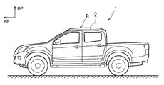
- FIG. 1 is a side view of a vehicle to which a roof rail is attached.
- FIG. 2 is a schematic explanatory view of the roof rail.
- FIG. 3 is an exploded perspective view of the intermediate bracket according to one embodiment of the present invention.
- FIG. 4 is a cross-sectional view showing a state where the roof rail is attached to a vehicle.
- FIG. 5 is a plan view showing a state where the roof rail is attached to the vehicle.
- FIG. 6 is a perspective view of the intermediate bracket from the inside in the vehicle width direction.
- FIG. 7 is a perspective view of the intermediate bracket from the outside in the vehicle width direction.
- FIG. 8 is a cross-sectional view corresponding to FIG. 4 when the mounting portion is provided on the second bracket.
- FIG. 4 is a side view of a vehicle to which a roof rail is attached.
- FIG. 2 is a schematic explanatory view of the roof rail.
- FIG. 3 is an exploded perspective view of the intermediate bracket according to one embodiment of the present
- FIG. 9 is a cross-sectional view corresponding to FIG. 4 in a case where a supported portion is provided on the intermediate bracket side and upper and lower support portions are provided on the roof rail side.
- FIG. 10 is a cross-sectional view corresponding to FIG. 4 in a case where a supported portion is provided on the intermediate bracket side and upper and lower support portions are provided on the roof rail side.
- FR indicates the front of the vehicle
- UP indicates the upper side
- IN indicates the inner side in the vehicle width direction.
- the front-rear direction means the front-rear direction of the vehicle
- the left-right direction means the left-right direction in a state where the vehicle faces the front.
- the roof rail device 8 As shown in FIG. 1, the roof rail device 8 according to the present embodiment is provided at a pair of left and right sides at both ends in the vehicle width direction of the roof panel 2 of the vehicle 1, and extends in a front-rear direction above the roof panel 2. It is attached to the roof panel 2.
- FIG. 1 shows only the left roof rail device 8. Further, since the roof rail device 8 is provided symmetrically on the left and right sides of the roof panel 2 and has substantially the same configuration, the left side will be described below and the right side description will be omitted.
- the roof rail device 8 includes a roof rail 10 extending in the front-rear direction above the roof panel 2, and a plurality of brackets 9 for attaching the roof rail 10 to the roof panel 2.
- the plurality of brackets 9 are attached to a pair of front and rear end brackets 5 attached to both front and rear ends of the roof rail 10, and the plurality of brackets 9 are attached to front and rear intermediate portions of the roof rail 10 in a state of being separated from each other (in the present embodiment, 2. ) Intermediate brackets (support brackets) 11.
- a roof rail 10 and a plurality of brackets 9 are sub-assembled.
- the roof rail mounting structure according to the present disclosure is applied to a mounting structure for mounting an intermediate portion of the roof rail 10 to the roof panel 2. Since the plurality of intermediate brackets 11 have substantially the same configuration, only one intermediate bracket 11 will be described below, and description of the other intermediate bracket 11 will be omitted.
- a groove 3 is formed at the outer end of the roof panel 2 in the vehicle width direction and extends in the front-rear direction while being recessed downward.
- a bolt insertion hole (roof-side through-hole) 4 is formed in the bottom plate 27 of the groove 3 of the roof panel 2 so as to penetrate in the vertical direction.
- the nut 6 is fixed to the lower surface of the bottom plate 27 at a position corresponding to the bolt insertion hole 4.
- the area around the bolt insertion hole 4 of the bottom plate 27 of the groove 3 of the roof panel 2 and the nut 6 function as a mounting portion 7 (a predetermined mounting position) for mounting the roof rail device 8.
- the roof rail 10 is arranged in the groove 3 of the roof panel 2 and is attached to the roof panel 2 via the intermediate bracket 11.
- the roof rail device 8 may be attached to the flat roof panel 2 without providing the groove 3 at the outer end of the roof panel 2 in the vehicle width direction.
- the roof rail 10 is formed in a substantially cylindrical shape extending in the front-rear direction.
- the upper rail portion 12 that partitions the upper part of the roof rail 10 and the lower rail plate portion (plate portion, supported portion, rail-side assembly portion) 13 that partitions the lower portion are vertically separated from each other.
- a generally rectangular bracket insertion hole 14 is formed in the rail upper plate portion 12 and penetrated in the up-down direction, and a bracket insertion hole of the rail lower plate portion 13 is formed in the rail lower plate portion 13 and penetrates in the vertical direction.
- a generally rectangular bracket insertion hole (rail-side assembly portion) 15 smaller than 14 is formed.
- the bracket insertion hole 14 of the rail upper plate portion 12 is formed to have a size that allows a first bracket 16 described later of the intermediate bracket 11 to be inserted into the roof rail 10 from above.
- the bracket insertion hole 14 of the rail upper plate portion 12 and the bracket insertion hole 15 of the rail lower plate portion 13 are arranged at positions vertically communicating with each other.
- the intermediate bracket 11 is composed of two brackets, a first bracket (first support bracket) 16 and a second bracket (second support bracket) 17.
- the first bracket 16 includes a lower plate portion (attachment portion) 18 that crosses the vertical direction, a first front plate portion (insertion portion) 19 that stands upright from the front edge of the lower plate portion 18 in the vehicle width direction, A front support plate portion (upper support portion, bracket-side assembling portion) 20 protruding forward from an upper end portion of the first front plate portion 19, and an upright standing along the vehicle width direction from a rear edge of the lower plate portion 18.
- a first rear plate portion (insertion portion) 21, a rear support plate portion (upper support portion, bracket-side assembly portion) 22 projecting rearward from an upper end of the first rear plate portion 21, and a lower plate portion 18.
- a thick-walled cylindrical portion (attaching portion) 23 projecting upward from the upper surface of the solid-state imaging device.
- the first bracket 16 is made of, for example, aluminum die-cast.
- the lower plate portion 18 of the first bracket 16 is formed in a substantially rectangular shape in a top view, having a size smaller than the bracket insertion hole 15 of the rail lower plate portion 13 of the roof rail 10.
- a bolt insertion hole (bracket-side through hole) 24 extending in the vertical direction is formed at a substantially central portion of the lower plate portion 18 of the first bracket 16.
- the bolt insertion hole 24 extends from the lower surface 25 of the lower plate portion 18 to the upper surface of a tubular portion 23 described later, and penetrates the lower plate portion 18 and the tubular portion 23 in the vertical direction.
- a protruding portion 26 protruding downward and having a rectangular shape as viewed from below is formed.
- the lower end of the bolt insertion hole 24 opens at a substantially central portion of the lower surface 25a of the protrusion 26.
- the lower surface 25a of the protruding portion 26 of the lower surface 25 of the lower plate portion 18 (the area around the bracket side through hole) is outside the protruding portion 26 of the lower surface 25 of the lower plate portion 18 (in the radial direction of the bolt insertion hole 24). (Outside), and is located below the outer peripheral region 25b surrounding the projecting portion 26 over the entire peripheral region.
- the first front plate portion 19 and the first rear plate portion 21 of the first bracket 16 are formed in a plate shape crossing the front-rear direction, and are provided symmetrically around the first bracket 16 and have substantially the same configuration.
- the first front plate portion 19 and the first rear plate portion 21 extend in a direction away from each other in a forward and backward direction from below to above and face each other. That is, the first front plate portion 19 and the first rear plate portion 21 are inclined with respect to the vertical direction.
- the first front plate portion 19 and the first rear plate portion 21 have a lower region 44 formed in an inverted trapezoidal shape that tapers downward from above in a front view (or a rear view), and an upper end of the lower region 44.
- the distance L1 in the front-rear direction between the front surface of the upper end portion of the upper region 45 of the first front plate portion 19 and the rear surface of the upper end portion of the upper region 45 of the first rear plate portion 21 is equal to the distance L1 of the bracket insertion hole 15 of the roof rail 10. It is less than the length (size) L2 in the front-rear direction.
- the length L3 in the vehicle width direction of the upper end of the lower region 44 of the first front plate portion 19 and the upper end of the lower region 44 of the first rear plate portion 21 is in the vehicle width direction of the bracket insertion hole 15 of the roof rail 10. Is less than the length (size) L4.
- the length L5 in the vehicle width direction of the upper end of the upper region 45 of the first front plate portion 19 and the upper end of the upper region 45 of the first rear plate portion 21 is the length of the upper end of the lower region 44 in the vehicle width direction.
- the length (size) L4 of the bracket insertion hole 15 of the roof rail 10 in the vehicle width direction is shorter than the length L3.
- a bottomed cylindrical first pin press-in hole 28 extending rearward from the front surface of the first front plate 19 is formed.
- the front support plate portion 20 and the rear support plate portion 22 of the first bracket 16 are formed in a plate shape crossing the vertical direction, and are provided symmetrically around the first bracket 16 and have substantially the same configuration.
- the length of the front support plate portion 20 and the rear support plate portion 22 in the vehicle width direction is the vehicle width of the upper end of the upper region 45 of the first front plate portion 19 and the upper end of the upper region 45 of the first rear plate portion 21.
- the length is substantially the same as the length L5 in the direction.
- the distance L6 between the front edge of the front support plate 20 and the rear edge of the rear support plate 22 in the front-rear direction is longer than the length (size) L2 of the bracket insertion hole 15 of the roof rail 10 in the front-rear direction. .
- the front support plate 20 and the rear support plate 22 are separated from the rail lower plate 13 of the roof rail 10.
- the front edge 13a defining the front of the bracket insertion hole 15 or the rear edge 13b defining the rear of the bracket insertion hole 15 in the rail lower plate portion 13 from above.
- the tubular portion 23 of the first bracket 16 is formed in a tubular shape extending in the up-down direction, and is disposed between the first front plate portion 19 and the first rear plate portion 21 to move upward from the upper surface of the lower plate portion 18. It protrudes and defines a bolt insertion hole 24 in the inner diameter part.
- the front end surface and the rear end surface of the cylindrical portion 23 are connected to the rear surface of the first front plate portion 19 or the front surface of the first rear plate portion 21 by a plate-shaped connecting portion 46 extending in the vertical direction.
- a thin plate-shaped sealing member 29 is attached to the upper surface of the cylindrical portion 23.
- the second bracket 17 is an aluminum die-cast, formed in a substantially rectangular cylindrical shape extending in the up-down direction, and defines an inner space 36 that allows the insertion of the first bracket 16 in an inner diameter portion.
- the second bracket 17 intersects the second front plate portion (lower support portion, bracket-side assembly portion) 30 intersecting the front-rear direction with the front-rear direction at a position separated rearward from the second front plate portion 30.
- the second rear plate portion (lower support portion, bracket-side assembly portion) 31 is connected to the vehicle width direction inner ends of the second front plate portion 30 and the second rear plate portion 31 across the vehicle width direction.
- an outer plate 33 intersecting the vehicle width direction and connecting outer ends of the second front plate 30 and the second rear plate 31 in the vehicle width direction.
- the inner space 36 of the second bracket 17 allows the first bracket 16 to be inserted from above.
- the second front plate portion 30 and the second rear plate portion 31 of the second bracket 17 are provided symmetrically around the second bracket 17 and have substantially the same configuration.
- the second front plate portion 30 and the second rear plate portion 31 extend in a direction in which they are separated from each other back and forth from below to above and face each other. That is, the second front plate portion 30 and the second rear plate portion 31 are inclined with respect to the vertical direction.
- the second front plate portion 30 and the second rear plate portion 31 are formed in an inverted trapezoidal shape that tapers downward from above in a front view (or a rear view).
- the distance L7 in the front-rear direction between the front surface of the upper end portion of the second front plate portion 30 and the rear surface of the upper end portion of the second rear plate portion 31 is the length (size) of the bracket insertion hole 15 of the roof rail 10 in the front-rear direction. ) Longer than L2.
- a second pin press-in hole 34 extending rearward from the front surface of the second front plate 30 and penetrating the second front plate 30 is formed.
- the second pin press-in hole 34 is formed at a position communicating with the first pin press-in hole 28 of the first front plate 19 of the first bracket 16 in a state where the first bracket 16 is inserted into the inner space 36 of the second bracket 17. Is done.
- the second bracket 17 and the first bracket 16 are connected to the second pin press-in hole 34 and the first bracket 16 from the front of the second front plate 30 in a state where the first bracket 16 is inserted into the inner space 36 of the second bracket 17.
- a protruding portion 42 that extends in the vehicle width direction while protruding downward is provided.
- the inner plate portion 32 of the second bracket 17 connects the upper ends of the second front plate portion 30 and the second rear plate portion 31 to each other.
- the upper surface of the inner plate portion 32 is disposed on substantially the same plane as the upper surfaces of the second front plate portion 30 and the second rear plate portion 31.
- the lower edge of the inner plate portion 32 is disposed above the lower ends of the second front plate portion 30 and the second rear plate portion 31.
- the outer plate portion 33 of the second bracket 17 connects the lower end portions of the second front plate portion 30 and the second rear plate portion 31 to each other.
- the upper edge of the outer plate portion 33 is disposed substantially at the center of the second front plate portion 30 and the second rear plate portion 31 in the height direction, and the lower edge of the outer plate portion 33 is formed by the second front plate portion 30 and It is arranged above the lower end of the second rear plate portion 31.
- a rail insertion space (space) 40 is defined between the lower surface of the rear support plate 22 and the lower surface of the rear support plate 22.
- the vertical size of the rail insertion space 40 is set slightly larger than the thickness of the rail lower plate portion 13 of the roof rail 10. That is, the distance between the upper surface of the second front plate portion 30 and the upper surface of the second rear plate portion 31 and the lower surface of the front support plate portion 20 and the lower surface of the rear support plate portion 22 is equal to the rail lower plate portion 13 of the roof rail 10. Is set to be longer than the plate thickness.
- a plurality of gaps 41 are provided between the first bracket 16 and the second bracket 17 so as to extend in the up-down direction and open on both upper and lower sides.
- the plurality of gaps 41 are the gap 41 a between the front surface of the first front plate portion 19 of the first bracket 16 and the rear surface of the second front plate portion 30 of the second bracket 17, and the first bracket 16.
- the gap 41b between the rear surface of the first rear plate portion 21 and the front surface of the second rear plate portion 31 of the second bracket 17, the inner edge of the lower plate portion 18 of the first bracket 16 in the vehicle width direction, and the second A gap 41c between the inner plate 32 of the bracket 17 and a gap 41d between the outer edge of the lower plate 18 of the first bracket 16 in the vehicle width direction and the outer plate 33 of the second bracket 17 are shown. .
- the plurality of gaps 41 allow water to flow from above to below, and the inside of the intermediate bracket 11 (e.g., above the lower plate portion 18 of the first bracket 16 in the inner space 36 of the second bracket 17) and the first It functions as a flow passage for discharging water that has entered between the bracket 16 and the second bracket 17 to the outside of the intermediate bracket 11.
- the first bracket 16 of the intermediate bracket 11 is inserted into the roof rail 10 from the bracket insertion hole 14 of the rail upper plate portion 12 of the roof rail 10, and The first front plate portion 19 and the first rear plate portion 21 of the bracket 16 are inserted into the bracket insertion holes 15 of the rail lower plate portion 13 from the lower plate portion 18 side.
- the first front plate 19, the first rear plate 21, the lower plate 18, and the cylindrical portion 23 of the first bracket 16 projecting downward from the bracket insertion hole 15 of the rail lower plate 13 of the roof rail 10.
- first bracket 16 and the second bracket 17 are assembled to the roof rail 10 in a state where they are fixed to each other, and the roof rail 10 and the intermediate bracket 11 are subassembled.
- the lower surface of the front support plate portion 20 and the lower surface of the rear support plate portion 22 of the first bracket 16 are close to or above the upper surface of the rail lower plate portion 13 of the roof rail 10.
- the upper surface of the second front plate portion 30, the upper surface of the second rear plate portion 31, and the upper surface of the inner plate portion 32 of the second bracket 17 are close to or below the lower surface of the rail lower plate portion 13 of the roof rail 10. Contact.
- the front support plate portion 20 and the rear support plate portion 22 of the first bracket 16 and the second front plate portion 30 and the second rear plate portion 31 of the second bracket 17 move the rail lower plate portion 13 of the roof rail 10 up and down.
- the rail lower plate 13 is disposed at a position to sandwich the rail lower plate 13 so as to be movable within a predetermined range in a direction crossing the vertical direction (for example, the front-rear direction or the left-right direction).
- the front surface of the first front plate portion 19 of the first bracket 16 is separated rearward from the front edge 13a of the rail lower plate portion 13 of the roof rail 10, and the rear surface of the first rear plate portion 21 of the first bracket 16 is , Away from the rear edge 13b of the rail lower plate portion 13 forward.
- the inner edges of the upper region 45 of the first front plate 19 and the first rear plate 21 of the first bracket 16 in the vehicle width direction are aligned with the bracket insertion holes 15 of the rail lower plate 13 of the roof rail 10 in the vehicle width direction.
- the outer edge of the upper side 45 of the first front plate portion 19 and the first rear plate portion 21 is separated from the inner edge portion 13c defining the inner side toward the outside in the vehicle width direction, and the outer edge of the rail lower plate portion 13
- the bracket insertion hole 15 is separated inward in the vehicle width direction from an outer edge portion 13d that defines the outside in the vehicle width direction. That is, the intermediate bracket 11 is subassembled in a state in which the intermediate bracket 11 can move within a predetermined range in a direction intersecting with the roof rail 10 in the vertical direction (the front-rear direction, the left-right direction, etc.).
- the roof rail device 8 When the roof rail device 8 is attached to the roof panel 2, first, the roof rail device 8 is disposed above the bottom plate 27 of the groove 3 with the roof rail 10 extending in the front-rear direction along the groove 3 of the roof panel 2. At this time, a thin plate-shaped sealing member 39 is interposed between the lower surface 25 of the lower plate portion 18 of the first bracket 16 and the upper surface of the bottom plate portion 27 of the roof panel 2.
- the seal member 39 is, for example, a thin plate-shaped seal member 39 formed of a porous material such as a sponge, and an opening (not shown) that exposes the protrusion 26 of the lower plate portion 18 of the first bracket 16 downward. Having.
- the sealing member 39 is a protrusion of the entire outer peripheral region 25 b of the lower surface 25 of the lower plate portion 18 of the first bracket 16 and the lower surface 43 of the second front plate portion 30 and the second rear plate portion 31 of the second bracket 17. It is formed in a size that covers the entire area 43b other than the area 42 from below.
- a seal member 39 is interposed so as to surround the projecting portion 26 over the entire peripheral area.
- the bracket 16 is inserted into the lower plate portion 18 of the bracket 16 and the bolt insertion hole 24 of the cylindrical portion 23 and screwed into the nut 6 on the lower surface side of the roof panel 2 to fasten and fix the intermediate bracket 11 and the roof panel 2. That is, the lower plate portion 18 and the cylindrical portion 23 of the first bracket 16 function as an attachment portion attached to the roof panel 2. Thus, the roof rail device 8 is attached to the roof panel 2.
- the intermediate bracket 11 is formed into a sub-assembly such that the intermediate bracket 11 can move within a predetermined range in a direction crossing the vertical direction (the front-rear direction, the left-right direction, or the like) with respect to the roof rail 10. Is done. Therefore, when the roof rail device 8 is attached to the roof panel 2, the position of the bolt insertion hole 24 of the intermediate bracket 11 and the position of the bolt insertion hole 4 of the roof panel 2 due to a manufacturing error of the roof rail 10 and the intermediate bracket 11. Even if the position is shifted in the direction crossing the vertical direction, manufacturing errors and the like of the roof rail 10 and the intermediate bracket 11 can be absorbed within the predetermined range. Therefore, the position of the bolt insertion hole 24 of the intermediate bracket 11 and the position of the bolt insertion hole 4 of the roof panel 2 can be easily matched, and the roof rail 10 can be attached to the roof panel 2.
- the rail lower plate portion 13 of the roof rail 10 is connected to the front support plate portion 20 and the rear support plate portion 22 of the first bracket 16 of the intermediate bracket 11 and the second front plate portion 30 and the second rear plate of the second bracket 17.
- the intermediate bracket 11 can be assembled to the roof rail 10 so as to be movable within the above-described predetermined range in a direction crossing the vertical direction with a simple structure in which the intermediate bracket 11 is vertically sandwiched and supported by the portion 31.
- the intermediate bracket 11 is constituted by the two brackets 16 and 17, the first front plate 19 and the first rear plate 21 of the first bracket 16 are inserted into the bracket insertion holes 15 of the roof rail 10, and the bracket insertion holes are provided.
- the intermediate bracket 11 can be easily assembled to the roof rail 10.
- a plurality of gaps 41 extending in the up-down direction and having both upper and lower sides open are provided.
- the plurality of gaps 41 allow water to flow from above to below, and the inside of the intermediate bracket 11 (e.g., above the lower plate portion 18 of the first bracket 16 in the inner space 36 of the second bracket 17) and the first It functions as a flow passage for discharging water that has entered between the bracket 16 and the second bracket 17 to the outside of the intermediate bracket 11. For this reason, water can be prevented from staying inside the intermediate bracket 11 or the like.
- the lower surface 25a of the protruding portion 26 of the lower plate portion 18 of the first bracket 16 is formed in a region around the bolt insertion hole 4 on the upper surface of the roof panel 2 (the bolt insertion portion of the upper surface 38 of the bottom plate 27 of the roof panel 2). (The area around the hole 4), so that the sealing property between the lower surface 25a of the protrusion 26 of the first bracket 16 and the upper surface 38 of the roof panel 2 can be ensured, and the bolt insertion of the roof panel 2 can be achieved. Intrusion of water into the hole 4 can be suppressed.
- the intermediate bracket 11 is attached to the roof rail 10 so as to be movable within a predetermined range in a direction crossing the vertical direction, the diameter of the bolt insertion hole 24 of the intermediate bracket 11 or the bolt insertion hole 4 of the roof panel 2. , The position of the bolt insertion hole 24 of the intermediate bracket 11 and the position of the bolt insertion hole 4 of the roof panel 2 can be easily adjusted. As described above, since the diameter of the bolt insertion hole 24 of the intermediate bracket 11 or the bolt insertion hole 4 of the roof panel 2 does not need to be increased, the lower surface 25 of the first bracket 16 and the upper surface 38 of the roof panel 2 are correspondingly increased. Large contact area can be secured, and the sealing property between the lower surface 25 of the first bracket 16 and the upper surface 38 of the roof panel 2 can be secured.
- a sealing member 39 is disposed between an outer peripheral region 25b of the lower surface 25 of the first bracket 16 that surrounds the entire periphery of the protruding portion 26 over the entire peripheral region and the upper surface 38 of the roof panel 2, and the outer peripheral region 25b The space between the roof panel 2 and the upper surface 38 is sealed. For this reason, the inflow of water between the lower surface 25a of the protrusion 26 of the first bracket 16 and the upper surface 38 of the roof panel 2 can be prevented by the seal member 39, and the roof member 2 can be inserted into the bolt insertion holes 4 of the roof panel 2. Intrusion of water can be reliably suppressed.
- the roof rail 10 and the intermediate bracket 11 are pre-assembled and sub-assembled, the position of the bolt insertion hole 24 of the intermediate bracket 11 and the bolt insertion hole 4 of the bottom plate 27 of the roof panel 2 are maintained. And the roof rail 10 can be attached to the roof panel 2.
- the sealing member 39 is not limited to the thin plate-shaped sealing member 39 formed of a porous material such as sponge, but is a lower surface 25 of the lower plate 18 of the first bracket 16 and an upper surface of the bottom plate 27 of the roof panel 2.
- the seal member may be made of another material or another shape as long as the seal member can be sealed between the first member and the second member.
- the seal member 39 may not be provided between the lower surfaces 25 and 43 of the intermediate bracket 11 and the upper surface 38 of the roof panel 2.
- the lower surface 25 of the lower plate portion 18 of the first bracket 16 is brought into surface contact with the area around the bolt insertion hole 4 on the upper surface 38 of the bottom plate portion 27 of the roof panel 2.
- a seal member may be interposed in the entire area between the lower surface 25 of the lower plate portion 18 and the upper surface 38 of the bottom plate portion 27 of the roof panel 2.
- a plurality of gaps 41a to 41d are provided between the first bracket 16 and the second bracket 17, but the gap 41 is not limited to this, and the plurality of gaps 41a to 41d are provided. Only one gap 41 of 41d may be provided. Alternatively, the gap 41 may not be provided between the first bracket 16 and the second bracket 17.
- the lower plate portion (attachment portion) 18 and the tubular portion (attachment portion) 23 are provided on the first bracket 16 as attachment portions for attaching the intermediate bracket 11 to the roof panel 2 side.
- the shape of the mounting portion is not limited to the above.
- only the lower plate portion 18 may function as the mounting portion without providing the first bracket 16 with the tubular portion 23.
- the mounting portion for mounting the intermediate bracket 11 to the roof panel 2 is provided on the first bracket 16.
- the first bracket (first support bracket) 51 of the intermediate bracket (support bracket) 50 includes a first front plate 19 and a first bracket 19 instead of the lower plate 18 and the tubular portion 23.
- a pair of left and right connection side plate portions 53 (only one connection side plate portion 53 is shown in FIG. 8) connecting the rear plate portion 21 is provided, and a second bracket (second support bracket) 52 is provided.
- a bottom plate ( (An attachment part) 54 In addition to the second front plate portion 30, the second rear plate portion 31, the inner plate portion 32, and the outer plate portion 33 (not shown in FIG. 8), a bottom plate ( (An attachment part) 54.
- the bottom plate portion 54 of the second bracket 52 has a bolt insertion hole (bracket side through hole) 55 penetrating vertically.
- the first bracket 16 has a first front plate portion (insertion portion) 19, a front support plate portion (upper support portion) 20, a first rear plate portion (insertion portion) 21, and a rear support plate.
- the portion (upper support portion) 22 is provided, the insertion portion of the first bracket 16 and the upper support portion are not limited thereto.
- left and right insertion portions that stand along both end edges of the lower plate portion 18 of the first bracket 16 in the vehicle width direction, and upper support portions that extend in directions away from the upper end edges of the left and right insertion portions. May be provided on the first bracket 16 instead of or in addition to the first front plate 19, the front support plate 20, the first rear plate 21, and the rear support plate 22.
- the second bracket 17 is formed in a substantially rectangular cylindrical shape extending in the vertical direction, but the shape of the second bracket 17 is not limited to this.
- the second bracket 17 only needs to have at least a lower support portion that is in proximity to or in contact with the lower surface of the rail lower plate portion 13 of the roof rail 10 while being fixed to the first bracket 16.
- the intermediate bracket 11 is configured by two brackets (the first bracket 16 and the second bracket 17), but may be configured by three or more brackets.
- the intermediate bracket 11 may be constituted by one bracket without being divided into a plurality of brackets.
- at least one of the roof rail 10 and the intermediate bracket may be provided with a structure capable of assembling the intermediate bracket movably within a predetermined range in a direction crossing the roof rail 10 in the vertical direction.
- the lower rail portion (supported portion, rail-side assembly portion) 13 of the roof rail 10 is connected to the front support plate portion (upper support portion) of the first bracket 16 of the intermediate bracket (support bracket) 11. , Bracket-side assembly part) 20 and rear support plate part (upper support part, bracket-side assembly part) 22, and second front plate part (lower support part, bracket-side assembly part) of the second bracket 17. ) 30 and the second rear plate portion (lower support portion, bracket-side assembly portion) 31, but the invention is not limited to this.
- the side assembly part) may be sandwiched and supported by upper and lower support parts (rail side assembly parts) provided on the roof rail 10 side.
- the plate portion (lower support portion, rail-side assembly portion) 62 allows the supported portion (bracket-side assembly portion) 64 of the intermediate bracket (support bracket) 63 to fall within a predetermined range in a direction crossing the vertical direction. May be movably supported.
- a bolt insertion hole 67 is formed in the lower rail portion 13 of the roof rail 10 instead of the bracket insertion hole 15, and a plurality of support members 65 ( FIG. 9 shows two support members 65.) are fixed by screws or welding.
- the support member 65 is disposed at a position spaced downward from the lower surface of the predetermined region 61 of the rail lower plate portion 13 to define a predetermined space 66 between the support member 65 and the predetermined region 61 of the rail lower plate portion 13.
- Each has a support plate portion 62.
- the intermediate bracket 63 has a tubular portion (attaching portion) 68 extending in the up-down direction, and a supported portion 64 projecting radially outward from the upper end of the tubular portion 68 in a flange shape.
- a bolt insertion hole (bracket side through hole) 69 penetrating in the vertical direction is formed in the cylindrical portion 68.
- the supported portion 64 of the intermediate bracket 63 is arranged in a space 66 between the predetermined region 61 of the rail lower plate portion 13 and the support plate portion 62 of the support member 65.
- the plate portion (lower support portion, rail-side assembly portion) 72 allows the supported portion (bracket-side assembly portion) 74 of the intermediate bracket (support bracket) 73 to fall within a predetermined range in a direction crossing the vertical direction. May be movably supported.
- a bolt insertion hole 67 is formed in the rail lower plate portion 13 of the roof rail 10 instead of the bracket insertion hole 15, and a support member 75 is screwed or welded to the lower surface side of the bolt insertion hole 67 of the rail lower plate portion 13. And so on.
- the support member 75 has a cylindrical portion 78 extending in the vertical direction, and a support plate portion 72 projecting radially outward from an upper end of the cylindrical portion 78 in a flange shape.
- the support plate portion 72 of the support member 75 is disposed at a position spaced downward from the lower surface of the predetermined region 71 of the rail lower plate portion 13, and a predetermined distance is provided between the support plate portion 72 and the predetermined region 71 of the rail lower plate portion 13.
- a space 76 is defined.
- the intermediate bracket 73 includes a bottom plate portion (attachment portion) 77, a plurality of side plate portions 80 rising from an outer edge of the bottom plate portion 77 (two side plate portions 80 are illustrated in FIG. 10), and a plurality of side plates.
- a plurality of supported portions 74 protruding from the upper end of the portion 80.
- a bolt insertion hole (bracket-side through-hole) 79 is formed at the center of the bottom plate portion 77 of the intermediate bracket 73 so as to penetrate vertically.
- a support member 75 on the roof rail 10 side is arranged between the plurality of side plate portions 80 of the intermediate bracket 73.
- the plurality of supported portions 74 of the intermediate bracket 73 project from upper end portions of the plurality of side plate portions 80 toward the support member 75 on the roof rail 10 side.
- the plurality of supported portions 74 of the intermediate bracket 73 are disposed in a space 76 between the predetermined region 71 of the rail lower plate portion 13 and the support plate portion 72 of the support member 75.
- two intermediate brackets 11 are provided at the intermediate portion of the roof rail 10, but one or three or more intermediate brackets 11 may be provided at the intermediate portion of the roof rail 10.
- the support bracket according to the present disclosure is applied to the intermediate bracket 11 for attaching the intermediate portion of the roof rail 10 to the roof panel 2, but the end of the roof rail 10 is attached to the roof panel 2. It may be applied to the end bracket 5 for attachment.
- the roof rail device, the support bracket, and the roof rail mounting structure according to the present disclosure can be widely applied to vehicles having a roof rail.
Landscapes
- Engineering & Computer Science (AREA)
- Mechanical Engineering (AREA)
- Body Structure For Vehicles (AREA)
- Fittings On The Vehicle Exterior For Carrying Loads, And Devices For Holding Or Mounting Articles (AREA)
Abstract
L'invention concerne un rail de toit 10 comportant une plaque inférieure de rail 13, et s'étendant dans une direction avant-arrière au-dessus d'un panneau de toit 2. Un premier crochet 16, qui est un crochet intermédiaire 11, comporte une plaque inférieure, une plaque de support avant 20, une plaque de support arrière 22 et une partie cylindrique. Un second crochet 17, qui est un crochet intermédiaire 11, comporte une seconde plaque avant 30 et une seconde plaque arrière 31. La plaque de support avant 20 et la plaque de support arrière 22 du premier crochet 16 et la seconde plaque avant 30 et la seconde plaque arrière 31 du second crochet 17 supportent la plaque inférieure de rail 13 de façon à permettre à la plaque inférieure de rail 13 de se déplacer sur une distance prescrite dans une direction qui coupe la direction verticale. La plaque inférieure et la partie cylindrique du premier crochet 16 sont montées sur le panneau de toit 2.
Priority Applications (1)
| Application Number | Priority Date | Filing Date | Title |
|---|---|---|---|
| CN201980042928.7A CN112368182B (zh) | 2018-07-04 | 2019-06-17 | 车顶纵梁装置、支承托架、以及车顶纵梁安装结构 |
Applications Claiming Priority (2)
| Application Number | Priority Date | Filing Date | Title |
|---|---|---|---|
| JP2018-127310 | 2018-07-04 | ||
| JP2018127310A JP7089697B2 (ja) | 2018-07-04 | 2018-07-04 | ルーフレール装置、サポートブラケット、及びルーフレール取付構造 |
Publications (1)
| Publication Number | Publication Date |
|---|---|
| WO2020008852A1 true WO2020008852A1 (fr) | 2020-01-09 |
Family
ID=69060206
Family Applications (1)
| Application Number | Title | Priority Date | Filing Date |
|---|---|---|---|
| PCT/JP2019/023967 Ceased WO2020008852A1 (fr) | 2018-07-04 | 2019-06-17 | Dispositif de rail de toit, crochet de support et structure de montage de rail de toit |
Country Status (3)
| Country | Link |
|---|---|
| JP (1) | JP7089697B2 (fr) |
| CN (1) | CN112368182B (fr) |
| WO (1) | WO2020008852A1 (fr) |
Families Citing this family (2)
| Publication number | Priority date | Publication date | Assignee | Title |
|---|---|---|---|---|
| JP6933632B2 (ja) * | 2018-12-12 | 2021-09-08 | 本田技研工業株式会社 | 物品固定装置および物品固定構造の組付け方法 |
| JP7412271B2 (ja) * | 2020-05-14 | 2024-01-12 | 三菱自動車工業株式会社 | 車両部品の固定構造 |
Citations (3)
| Publication number | Priority date | Publication date | Assignee | Title |
|---|---|---|---|---|
| JP2007055359A (ja) * | 2005-08-23 | 2007-03-08 | Aisin Seiki Co Ltd | ルーフレール支持脚、ルーフレール及びルーフレール組付方法 |
| WO2017005808A1 (fr) * | 2015-07-07 | 2017-01-12 | Süddeutsche Aluminium Manufaktur GmbH | Galerie de toit pour véhicule automobile, véhicule automobile comportant une galerie de toit et procédé de production d'une telle galerie de toit |
| JP2017019457A (ja) * | 2015-07-14 | 2017-01-26 | アイシン精機株式会社 | ルーフレール装置 |
Family Cites Families (2)
| Publication number | Priority date | Publication date | Assignee | Title |
|---|---|---|---|---|
| JP4683061B2 (ja) * | 2008-03-21 | 2011-05-11 | 日産自動車株式会社 | ルーフラック取付構造及びルーフラック取付方法 |
| DE102015013598B4 (de) * | 2015-10-21 | 2021-04-08 | Audi Ag | Toleranzausgleichselement und zugehörige Kraftfahrzeugkarosserie |
-
2018
- 2018-07-04 JP JP2018127310A patent/JP7089697B2/ja active Active
-
2019
- 2019-06-17 WO PCT/JP2019/023967 patent/WO2020008852A1/fr not_active Ceased
- 2019-06-17 CN CN201980042928.7A patent/CN112368182B/zh active Active
Patent Citations (3)
| Publication number | Priority date | Publication date | Assignee | Title |
|---|---|---|---|---|
| JP2007055359A (ja) * | 2005-08-23 | 2007-03-08 | Aisin Seiki Co Ltd | ルーフレール支持脚、ルーフレール及びルーフレール組付方法 |
| WO2017005808A1 (fr) * | 2015-07-07 | 2017-01-12 | Süddeutsche Aluminium Manufaktur GmbH | Galerie de toit pour véhicule automobile, véhicule automobile comportant une galerie de toit et procédé de production d'une telle galerie de toit |
| JP2017019457A (ja) * | 2015-07-14 | 2017-01-26 | アイシン精機株式会社 | ルーフレール装置 |
Also Published As
| Publication number | Publication date |
|---|---|
| CN112368182A (zh) | 2021-02-12 |
| CN112368182B (zh) | 2023-06-16 |
| JP2020006741A (ja) | 2020-01-16 |
| JP7089697B2 (ja) | 2022-06-23 |
Similar Documents
| Publication | Publication Date | Title |
|---|---|---|
| US8636396B2 (en) | Vehicle body front structure | |
| CN110901362A (zh) | 车辆下部结构 | |
| WO2020008852A1 (fr) | Dispositif de rail de toit, crochet de support et structure de montage de rail de toit | |
| CN106660586A (zh) | 用于支撑在机动车中的前置马达的纵向支撑装置 | |
| CN100450854C (zh) | 支承座装置的安装构造 | |
| CN104275996B (zh) | 保险杠构件的螺母安装构造 | |
| JP3533644B2 (ja) | 自動車のシート装着装置 | |
| JP6326690B2 (ja) | 車両のドア構造 | |
| CN105473423A (zh) | 车辆的翼子板支承构造 | |
| JP4151024B2 (ja) | 車両前部構造 | |
| KR101563174B1 (ko) | 차체 조립용 스터드 볼트유닛 | |
| CN116494744A (zh) | 用于专用车辆的框架结构 | |
| JP4427076B2 (ja) | 前部車体構造 | |
| JP2018050661A (ja) | ラックの側枠構造体 | |
| JP2017030548A (ja) | ヘッドランプの取付構造 | |
| JP2002308151A (ja) | キャブオーバー型車のキャブフロア構造 | |
| JP6525243B2 (ja) | 車両のハイルーフ取付構造 | |
| JP2007055400A (ja) | 車両前部構造 | |
| KR102224808B1 (ko) | 차량용 리어플로어구조 | |
| JP6508136B2 (ja) | 車両前部構造 | |
| JP7290134B2 (ja) | 電動車両の下部構造 | |
| JP3281310B2 (ja) | 自動車の車体前部構造 | |
| JPH0325066A (ja) | 駐車ブレーキケーブルの配索構造 | |
| KR100410755B1 (ko) | 프론트사이드멤버와 서브프레임 사이의 체결용 너트구조 | |
| JP5056028B2 (ja) | 車両用シートフレーム |
Legal Events
| Date | Code | Title | Description |
|---|---|---|---|
| 121 | Ep: the epo has been informed by wipo that ep was designated in this application |
Ref document number: 19830858 Country of ref document: EP Kind code of ref document: A1 |
|
| NENP | Non-entry into the national phase |
Ref country code: DE |
|
| 122 | Ep: pct application non-entry in european phase |
Ref document number: 19830858 Country of ref document: EP Kind code of ref document: A1 |