WO2020008884A1 - Procédé et système de traitement par osmose inverse - Google Patents
Procédé et système de traitement par osmose inverse Download PDFInfo
- Publication number
- WO2020008884A1 WO2020008884A1 PCT/JP2019/024317 JP2019024317W WO2020008884A1 WO 2020008884 A1 WO2020008884 A1 WO 2020008884A1 JP 2019024317 W JP2019024317 W JP 2019024317W WO 2020008884 A1 WO2020008884 A1 WO 2020008884A1
- Authority
- WO
- WIPO (PCT)
- Prior art keywords
- raw water
- water
- reverse osmosis
- heat
- heated
- Prior art date
- Legal status (The legal status is an assumption and is not a legal conclusion. Google has not performed a legal analysis and makes no representation as to the accuracy of the status listed.)
- Ceased
Links
Images



Classifications
-
- B—PERFORMING OPERATIONS; TRANSPORTING
- B01—PHYSICAL OR CHEMICAL PROCESSES OR APPARATUS IN GENERAL
- B01D—SEPARATION
- B01D61/00—Processes of separation using semi-permeable membranes, e.g. dialysis, osmosis or ultrafiltration; Apparatus, accessories or auxiliary operations specially adapted therefor
- B01D61/02—Reverse osmosis; Hyperfiltration ; Nanofiltration
- B01D61/025—Reverse osmosis; Hyperfiltration
-
- B—PERFORMING OPERATIONS; TRANSPORTING
- B01—PHYSICAL OR CHEMICAL PROCESSES OR APPARATUS IN GENERAL
- B01D—SEPARATION
- B01D61/00—Processes of separation using semi-permeable membranes, e.g. dialysis, osmosis or ultrafiltration; Apparatus, accessories or auxiliary operations specially adapted therefor
- B01D61/02—Reverse osmosis; Hyperfiltration ; Nanofiltration
- B01D61/04—Feed pretreatment
-
- B—PERFORMING OPERATIONS; TRANSPORTING
- B01—PHYSICAL OR CHEMICAL PROCESSES OR APPARATUS IN GENERAL
- B01D—SEPARATION
- B01D61/00—Processes of separation using semi-permeable membranes, e.g. dialysis, osmosis or ultrafiltration; Apparatus, accessories or auxiliary operations specially adapted therefor
- B01D61/02—Reverse osmosis; Hyperfiltration ; Nanofiltration
- B01D61/08—Apparatus therefor
-
- B—PERFORMING OPERATIONS; TRANSPORTING
- B01—PHYSICAL OR CHEMICAL PROCESSES OR APPARATUS IN GENERAL
- B01D—SEPARATION
- B01D61/00—Processes of separation using semi-permeable membranes, e.g. dialysis, osmosis or ultrafiltration; Apparatus, accessories or auxiliary operations specially adapted therefor
- B01D61/02—Reverse osmosis; Hyperfiltration ; Nanofiltration
- B01D61/10—Accessories; Auxiliary operations
-
- C—CHEMISTRY; METALLURGY
- C02—TREATMENT OF WATER, WASTE WATER, SEWAGE, OR SLUDGE
- C02F—TREATMENT OF WATER, WASTE WATER, SEWAGE, OR SLUDGE
- C02F1/00—Treatment of water, waste water, or sewage
- C02F1/44—Treatment of water, waste water, or sewage by dialysis, osmosis or reverse osmosis
-
- C—CHEMISTRY; METALLURGY
- C02—TREATMENT OF WATER, WASTE WATER, SEWAGE, OR SLUDGE
- C02F—TREATMENT OF WATER, WASTE WATER, SEWAGE, OR SLUDGE
- C02F1/00—Treatment of water, waste water, or sewage
- C02F1/44—Treatment of water, waste water, or sewage by dialysis, osmosis or reverse osmosis
- C02F1/441—Treatment of water, waste water, or sewage by dialysis, osmosis or reverse osmosis by reverse osmosis
-
- F—MECHANICAL ENGINEERING; LIGHTING; HEATING; WEAPONS; BLASTING
- F25—REFRIGERATION OR COOLING; COMBINED HEATING AND REFRIGERATION SYSTEMS; HEAT PUMP SYSTEMS; MANUFACTURE OR STORAGE OF ICE; LIQUEFACTION SOLIDIFICATION OF GASES
- F25B—REFRIGERATION MACHINES, PLANTS OR SYSTEMS; COMBINED HEATING AND REFRIGERATION SYSTEMS; HEAT PUMP SYSTEMS
- F25B1/00—Compression machines, plants or systems with non-reversible cycle
-
- F—MECHANICAL ENGINEERING; LIGHTING; HEATING; WEAPONS; BLASTING
- F25—REFRIGERATION OR COOLING; COMBINED HEATING AND REFRIGERATION SYSTEMS; HEAT PUMP SYSTEMS; MANUFACTURE OR STORAGE OF ICE; LIQUEFACTION SOLIDIFICATION OF GASES
- F25B—REFRIGERATION MACHINES, PLANTS OR SYSTEMS; COMBINED HEATING AND REFRIGERATION SYSTEMS; HEAT PUMP SYSTEMS
- F25B30/00—Heat pumps
- F25B30/02—Heat pumps of the compression type
-
- B—PERFORMING OPERATIONS; TRANSPORTING
- B01—PHYSICAL OR CHEMICAL PROCESSES OR APPARATUS IN GENERAL
- B01D—SEPARATION
- B01D2313/00—Details relating to membrane modules or apparatus
- B01D2313/22—Cooling or heating elements
- B01D2313/221—Heat exchangers
-
- Y—GENERAL TAGGING OF NEW TECHNOLOGICAL DEVELOPMENTS; GENERAL TAGGING OF CROSS-SECTIONAL TECHNOLOGIES SPANNING OVER SEVERAL SECTIONS OF THE IPC; TECHNICAL SUBJECTS COVERED BY FORMER USPC CROSS-REFERENCE ART COLLECTIONS [XRACs] AND DIGESTS
- Y02—TECHNOLOGIES OR APPLICATIONS FOR MITIGATION OR ADAPTATION AGAINST CLIMATE CHANGE
- Y02A—TECHNOLOGIES FOR ADAPTATION TO CLIMATE CHANGE
- Y02A30/00—Adapting or protecting infrastructure or their operation
- Y02A30/27—Relating to heating, ventilation or air conditioning [HVAC] technologies
- Y02A30/274—Relating to heating, ventilation or air conditioning [HVAC] technologies using waste energy, e.g. from internal combustion engine
Definitions
- the present invention relates to a reverse osmosis treatment method and system for treating water using a reverse osmosis membrane device, and particularly to a reverse osmosis treatment method and system for heating water supplied to a reverse osmosis membrane device with a heat pump.
- the feed water temperature is adjusted to maintain the treated water volume (maintaining the flux by preventing a decrease in the viscosity of water and improving the recovery rate by increasing the saturation solubility of silica). It is heated to about 25 ° C. Steam, hot water, electric heaters, and the like are used to heat the supply water, and energy is consumed.
- Japanese Patent Application Laid-Open No. 2012-91118 describes that the feed water of the RO apparatus is heated to 23 to 25 ° C. by a heat pump, but the same publication discloses a specific description of the heat source of the heat pump. Not done.
- the present invention aims to reduce the heating cost in a reverse osmosis treatment method and system in which water supplied to an RO device is heated by a heat pump.
- the reverse osmosis treatment method of the present invention is a reverse osmosis treatment method in which raw water is heated by a heat pump and then subjected to membrane separation treatment by a reverse osmosis membrane device, wherein a warm medium flowing out of a heat exchanger of a refrigeration system as a heat source fluid of the heat pump Is used.
- the reverse osmosis treatment system of the present invention is a reverse osmosis treatment device in which raw water is heated by a heat pump and then subjected to membrane separation treatment by a reverse osmosis membrane device, wherein a warm medium flowing out of a heat exchanger of a refrigeration system as a heat source fluid of the heat pump. Is used.
- the raw water heated by the heat pump is heated by the second heat exchanger and then supplied to the reverse osmosis device.
- steam from the boiler is supplied to the second heat exchanger as a heat source fluid for heating raw water.
- At least a part of the raw water heated by the heat pump is supplied to the boiler as boiler feed water.
- a water supply tank in which water is circulated between the heat transfer tube of the condenser of the heat pump and raw water is supplied to the water supply tank.
- the raw water is circulated and heated in, and the heated raw water is supplied from the water supply tank to the reverse osmosis device.
- a water supply tank in which water is circulated between the heat transfer tube of the condenser of the heat pump and raw water is supplied to the water supply tank.
- the raw water is circulated and heated, and at least a part of the heated raw water is supplied to the boiler as boiler water supply.
- the refrigeration system includes a refrigerator main body, and the heat exchanger into which a refrigerant from the refrigerator main body is introduced and a warm medium flows out. A part of the warming medium to be returned is returned to the refrigerator main body, the remaining part is introduced into the evaporator of the heat pump, and the medium cooled by the evaporator is returned to the refrigerant inlet side of the heat exchanger.
- the refrigeration system includes a refrigerator main body, and the heat exchanger into which a refrigerant from the refrigerator main body is introduced and a warm medium flows out. A part of the warming medium to be returned is returned to the refrigerator main body, the remaining part is introduced into the evaporator of the heat pump, and the medium whose temperature has been lowered by the evaporator is returned to the refrigerator main body.
- the present invention it is possible to reduce the heating cost of the feed water by heating the feed water to the RO device with a heat pump using the heat medium flowing out of the heat exchanger of the refrigeration system as a heat source.
- the temperature of the warming medium flowing out of the heat exchanger of the refrigeration system is decreased by the evaporator of the heat pump, so that the refrigeration load of the refrigerator can be reduced.
- the power consumption of the refrigerator main body can be reduced, and the total benefit generated by installing the heat pump can be increased.
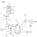
- the raw water to be subjected to the RO treatment is supplied from a pipe 1 to a condenser 13 of a heat pump 10 by a pump 2, heated, and then passes through a heat exchanger (second heat exchanger) 4 using steam as a heat source from a pipe 3. It is supplied to the RO device 6 via the pipe 5.
- the permeated water of the RO device 6 is taken out of the pipe 7 as treated water, and the concentrated water flows out of the pipe 8.
- the type of boiler for supplying steam to the heat exchanger 4 is not particularly limited, and may be any of a small once-through boiler, a water tube boiler, a round boiler, and a waste heat boiler. It should be noted that during normal operation, heating by steam is not necessary, but it is used for heating, for example, when the refrigerator body 21 is stopped or when the RO device 6 is started, which will be described later. However, if necessary, the RO feedwater may be heated by the heat exchanger 4 even during normal operation.
- the heat pump 10 has a well-known configuration, and introduces a heat medium, such as chlorofluorocarbon alternative, from the evaporator 11 to the condenser 13 at a high temperature by adiabatic compression in the compressor 12, and transfers the heat medium from the condenser 13 to the expansion valve 14. Is introduced into the evaporator 11 through the, and is adiabatically expanded to lower the temperature. Raw water is passed through the heat transfer tube 13 a provided in the condenser 13 via the pump 2, and exchanges heat with a high-temperature heat medium to be heated.
- a heat medium such as chlorofluorocarbon alternative
- the refrigeration system 20 is configured to transfer a refrigerant cooled by a refrigerator main body 21 such as a turbo refrigerator or an absorption refrigerator to a heat exchanger such as an air conditioner via a pipe 22 from a medium delivery unit 21a of the refrigerator main body 21.
- a refrigerator main body 21 such as a turbo refrigerator or an absorption refrigerator
- a heat exchanger such as an air conditioner
- the refrigeration system 20 is configured to transfer a refrigerant cooled by a refrigerator main body 21 such as a turbo refrigerator or an absorption refrigerator to a heat exchanger such as an air conditioner via a pipe 22 from a medium delivery unit 21a of the refrigerator main body 21.
- First heat exchanger to absorb the heat of the surroundings and cool the surroundings.
- a part of the warming medium which has been heated by absorbing the surrounding heat in the heat exchanger 24, is transferred from the heat exchanger 24 via the medium circulation pump 25, the pipe 26, and the valve 27 to the medium return portion 21 b of the refrigerator body 21.
- the remaining portion of the warm medium flowing out of the heat exchanger 24 flows through the heat transfer tube 11a of the evaporator 11 via the pipe 31 branched from the pipe 26 and the valve 32, exchanges heat with the heat pump heat medium, and cools down by cooling. It becomes a medium and flows out to the pipe 33.
- the pipe 33 is connected to the pipe 22, and the refrigerant from the pipe 33 joins with the refrigerant from the refrigerator main body 21 and flows into the heat exchanger 24.
- the heating medium flowing out of the heat exchanger 24 is used as the heat source fluid flowing through the heat transfer tube 11a of the evaporator 11 of the heat pump 10.
- the refrigerant whose temperature has been lowered by passing through the heat transfer tube 11 a of the evaporator 11 of the heat pump 10 is returned to the heat exchanger 24.
- the refrigerator main body 21 of the refrigeration system 20 uses cold water from the cooling tower 40 as a low-temperature fluid for cooling.
- the cooling water sprinkled from the water sprinkling pipe 41 comes into contact with the air introduced from the louver 43 while flowing down the filler layer 42, and is cooled by the latent heat of evaporation to become cold water, and the pit 44 (cooling tower) (Lower tank). Air containing steam is exhausted to the atmosphere by a fan 48.
- the cold water in the pit 44 is supplied to the refrigerator main body 21 via a pump 45 and a pipe 46, and exchanges heat to raise the temperature.
- the warm return water from the refrigerator main body 21 is returned to the sprinkling pipe 41 via the pipe 47.
- the raw water is heated by the heat pump 10, then, if necessary, is heated by the heat exchanger 4, and is supplied to the RO device 6.
- a heating medium flowing out of a heat exchanger 24 such as an air conditioner installed in the refrigeration system 20 is used as a heat source of the heat pump 10, and the refrigeration load of the refrigerator main body 21 can be reduced. it can.
- the power consumption of the refrigerator main body 21 can be reduced, the power consumed by the heat pump 10 is almost offset. For this reason, since the amount of reduction of the steam for heating can be directly recorded as a benefit, the investment in the heat pump can be quickly recovered.
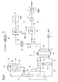
- the refrigerant sent from the refrigerator main body 21 via the pipe 22 and the refrigerant sent from the evaporator 11 via the pipe 33 are combined to form an air conditioner or the like.
- the warm medium flowing out of the heat exchanger 24 is sent out to a pipe 28 by a medium circulation pump 25.
- a part of the sent warm medium is circulated to the medium return part 21b of the refrigerator main body 21 via the valve 29 and the pipe 30.
- the remaining portion of the heating medium sent to the pipe 28 flows through the heat transfer tube 11a of the evaporator 11 via the pipe 35 and the valve 36 branched from the pipe 28, exchanges heat with the heat pump heat medium, and cools down by cooling. And merges with the pipe 30 from the pipe 37 and returns to the medium return portion 21b of the refrigerator main body 21.
- FIG. 2 The other configuration of FIG. 2 is the same as that of FIG. 1, and the same reference numerals indicate the same parts.
- a heating medium flowing out of a heat exchanger 24 such as an air conditioner installed in a refrigeration system 20 is used as a heat source of the heat pump 10.
- the refrigeration load of the machine body 21 can be reduced.
- raw water (20 ° C.) is heated to 25 ° C., subjected to RO treatment at 100 m 3 / h, and a centrifugal chiller (500 RT) is operated as a refrigerator main body 21 at a COP (coefficient of performance) of 5
- the medium of the refrigerator main body 21 is water
- the inflow water (warm medium) temperature of the refrigerator main body return portion 21b is 12 ° C.
- the outflow water (refrigerant) temperature of the refrigerator main body delivery portion 21a is 7 ° C.
- a heat pump 470 kW
- the raw water is heated from 20 ° C. to 25 ° C.
- the energy cost will be 80% or less as compared with the case of supplying with three small once-through boilers (equivalent evaporation 2000 kg / h, fuel LNG, steam pressure 0.7 MPa).
- the energy cost of the system in Fig. 1 was estimated to be 90% or less compared to the case where raw water is heated from 20 ° C to 25 ° C using only a heat pump.
- the entire amount of raw water heated by passing through the heat transfer tube 13 a of the condenser 13 of the heat pump 10 is sent from the pipe 3 to the heat exchanger 4, and is supplied to the heat exchanger 4 as a heat source fluid. Steam is supplied from the boiler.
- the pipe 3 is branched into two systems of pipes 50 and 60.
- the heated raw water flowing into the pipe 50 is sent to the heat exchanger 4 via the valve 51, the water supply tank 52, and the pipe 53.
- a pipe 86 provided with a valve 85 is connected to the water supply tank 52 in order to supply raw water not heated by the heat pump 10 (hereinafter sometimes referred to as “unheated raw water”) to the water supply tank 52.
- the heated raw water flowing into the pipe 60 is sent to the water supply tank 64 via the valve 61, the first water softener 62 and the pipe 63.
- the boiler water that has passed through the second water softener 65 is also introduced into the water supply tank 64 via the pipe 66.
- Each of the water softeners 62 and 65 has a container and an ion-exchange resin filled in the container, and uses raw water or boiler water as soft water.
- the boiler water may be water from the same water source as the raw water, or may be water from another water source.
- the water in the water supply tank 64 is supplied to the boiler 70 via the pipe 67.
- the steam generated in the boiler 70 is supplied to the heat exchanger 4 via the pipe 71.
- Raw water from the pipe 53 is heated by the heat exchanger 4 and supplied to the RO device 6.
- the condensed water generated by the condensation of the steam in the heat exchanger 4 may be sent to the water supply tank 64.
- FIG. 3 The other configurations in FIG. 3 are the same as those in FIG. 1, and the same reference numerals denote the same parts.
- FIG. 3 the configurations of the heat exchanger 24, the refrigerator 20, and the cooling tower 40 connected to the heat pump 10 are as shown in FIG. 1, but may be as shown in FIG.
- not only the water supply to the RO device 6 but also a part of the water supply to the boiler 70 can be heated by one heat pump 10.
- the supply destination of the heating raw water can be switched or the supply amount can be adjusted by the valve 51 and the valve 61. Then, the raw water supplied by the heat pump 10 is preferentially supplied to the RO device 6 using the valve 51 and the valve 61, and the surplus of the heated raw water is supplied to the boiler 70, whereby the raw water supplied to the RO device 6 is supplied. It is possible to effectively reduce the amount of steam for heating, and to effectively use the raw water heated by the heat pump 10.
- the valves 51 and 61 are adjusted so that the entire amount of the supplied water to the RO device 6 is used as the raw water to be heated.
- the surplus heating water is sent to the water supply tank 64 and used as boiler water.
- the valve 51, the valve 61, and the valve 85 are adjusted to adjust the feed water of the RO device 6 to the set temperature.
- the surplus amount of the heated raw water is supplied to the water supply tank 64. In this way, the raw water heated by the heat pump can be effectively used throughout the year.
- the supply destination of the heating raw water may be switched depending on the temperature of the non-heating raw water or the season. For example, when the temperature of the non-heated raw water exceeds a predetermined temperature, or in summer, the entire amount of the supply water of the RO device 6 is the non-heated raw water, and the valves 51, 61 and 85 may be adjusted. Further, when the temperature of the non-heated raw water is equal to or lower than a predetermined temperature, or in a season other than summer, the entire amount of the supply water of the RO device 6 is used as the raw water for heating, and the surplus of the raw water for heating is used as the boiler water supply. The valves 51, 61 and 85 may be adjusted.
- the raw water heated by the condenser 13 of the heat pump 10 is directly sent to the pipe 3, but in the system of FIG. 4, the raw water from the pipe 1 is introduced into the water supply tank 80, The internal raw water is sent to the heat transfer tube 13 a of the condenser 13 via the pump 81 and the pipe 82. The heated raw water flowing out of the heat transfer tube 13a is returned to the water supply tank 80 via the pipe 83. Thus, the temperature of the raw water in the water supply tank 80 increases. The high temperature raw water in the water supply tank 80 is sent to the pipe 3 via the pump 84.
- FIG. 4 The other configurations in FIG. 4 are the same as those in FIG. 3, and the same reference numerals indicate the same parts.
- the same effects as those of the system of FIG. 3 can be obtained by the system of FIG.
- the raw water is circulated through the water supply tank 80 and the condenser 13, so that the raw water heated to a higher temperature than in the case of FIG.
- FIG. 4 the configurations of the heat exchanger 24, the refrigerator 20, and the cooling tower 40 connected to the heat pump 10 are as shown in FIG. 1, but may be as shown in FIG.
- Table 1 shows the results of a trial calculation of the steam cost when the apparatus shown in Fig. 3 was operated under the following conditions.
- the water supply tank 80, the pump 81, the pipes 82 and 83, and the pump 84 are installed in the system of FIG.
- the raw water is heated by circulating between the heat transfer tube 13a and the water supply tank 80.
- the heated raw water is sent from the pump 84 to only the RO device 6 via the pipe 3.
- raw water heated to a higher temperature than in the case of FIG. 1 is sent to the RO device.
- the steam heat exchanger 4 is used, but a heat exchanger using heat other than steam as a heat source may be installed instead of the steam heat exchanger 4.
Landscapes
- Engineering & Computer Science (AREA)
- Chemical & Material Sciences (AREA)
- Water Supply & Treatment (AREA)
- Nanotechnology (AREA)
- Chemical Kinetics & Catalysis (AREA)
- Hydrology & Water Resources (AREA)
- Life Sciences & Earth Sciences (AREA)
- Environmental & Geological Engineering (AREA)
- Organic Chemistry (AREA)
- Physics & Mathematics (AREA)
- Mechanical Engineering (AREA)
- Thermal Sciences (AREA)
- General Engineering & Computer Science (AREA)
- Separation Using Semi-Permeable Membranes (AREA)
Abstract
L'eau brute est chauffée par le condenseur 13 d'une thermopompe 10 puis acheminée à un dispositif d'OI 6 à travers un échangeur de chaleur 4 en utilisant de la vapeur comme source de chaleur. Une partie d'un milieu chaud qui s'écoule à partir de l'échangeur de chaleur 24 d'un système de réfrigération 20 est mise en circulation à travers le tube de transfert de chaleur 11a de l'évaporateur 11 de la thermopompe 10. Le milieu dont la température a chuté en passant à travers le tube de transfert de chaleur 11a est mis en circulation et acheminé à l'échangeur de chaleur 24. Le système de réfrigération 20 fait circuler un réfrigérant à partir du corps principal d'un appareil réfrigérant 21 à travers l'échangeur de chaleur 24 tel qu'un climatiseur.
Priority Applications (3)
| Application Number | Priority Date | Filing Date | Title |
|---|---|---|---|
| KR1020207035981A KR102477968B1 (ko) | 2018-07-06 | 2019-06-19 | 역침투 처리 방법 및 시스템 |
| CN201980045228.3A CN112384479B (zh) | 2018-07-06 | 2019-06-19 | 反渗透处理方法及系统 |
| JP2019533667A JP6777236B2 (ja) | 2018-07-06 | 2019-06-19 | 逆浸透処理方法及びシステム |
Applications Claiming Priority (2)
| Application Number | Priority Date | Filing Date | Title |
|---|---|---|---|
| JP2018129257 | 2018-07-06 | ||
| JP2018-129257 | 2018-07-06 |
Publications (1)
| Publication Number | Publication Date |
|---|---|
| WO2020008884A1 true WO2020008884A1 (fr) | 2020-01-09 |
Family
ID=69060581
Family Applications (1)
| Application Number | Title | Priority Date | Filing Date |
|---|---|---|---|
| PCT/JP2019/024317 Ceased WO2020008884A1 (fr) | 2018-07-06 | 2019-06-19 | Procédé et système de traitement par osmose inverse |
Country Status (5)
| Country | Link |
|---|---|
| JP (1) | JP6777236B2 (fr) |
| KR (1) | KR102477968B1 (fr) |
| CN (1) | CN112384479B (fr) |
| TW (1) | TWI781329B (fr) |
| WO (1) | WO2020008884A1 (fr) |
Cited By (2)
| Publication number | Priority date | Publication date | Assignee | Title |
|---|---|---|---|---|
| JP2021011987A (ja) * | 2019-07-08 | 2021-02-04 | 栗田工業株式会社 | ヒートポンプシステム |
| WO2022013977A1 (fr) * | 2020-07-15 | 2022-01-20 | 栗田工業株式会社 | Système de pompe à chaleur |
Citations (9)
| Publication number | Priority date | Publication date | Assignee | Title |
|---|---|---|---|---|
| JPS634808A (ja) * | 1986-06-24 | 1988-01-09 | Takuma Co Ltd | 逆浸透膜装置システム |
| JPH01130785A (ja) * | 1987-11-18 | 1989-05-23 | Ishikawajima Harima Heavy Ind Co Ltd | オゾン水殺菌装置 |
| JPH07167525A (ja) * | 1993-12-16 | 1995-07-04 | Shimizu Corp | 冷却排熱利用給湯ヒートポンプシステム |
| JP2006159003A (ja) * | 2004-12-02 | 2006-06-22 | Mayekawa Mfg Co Ltd | 超純水の加熱冷却方法及び装置 |
| JP2012091118A (ja) * | 2010-10-27 | 2012-05-17 | Japan Organo Co Ltd | 水処理システム及び水処理方法 |
| CN204702545U (zh) * | 2015-06-04 | 2015-10-14 | 杭州英普水处理技术有限公司 | 一种反渗透原水进水加热装置 |
| JP2016107178A (ja) * | 2014-12-02 | 2016-06-20 | 三浦工業株式会社 | 水処理システム |
| JP2018027256A (ja) * | 2016-08-19 | 2018-02-22 | 日本ウォーターシステム株式会社 | 水処理装置 |
| WO2018051552A1 (fr) * | 2016-09-14 | 2018-03-22 | 栗田工業株式会社 | Dispositif de production d'eau ultrapure |
Family Cites Families (6)
| Publication number | Priority date | Publication date | Assignee | Title |
|---|---|---|---|---|
| JP5325431B2 (ja) * | 2008-02-29 | 2013-10-23 | パナソニック株式会社 | 冷凍装置の廃熱回収装置 |
| KR101577125B1 (ko) * | 2010-10-27 | 2015-12-11 | 오르가노 가부시키가이샤 | 수처리 시스템 및 수처리 방법 |
| JP5971088B2 (ja) * | 2012-11-08 | 2016-08-17 | 三浦工業株式会社 | ボイラ給水加熱システム |
| JP6532494B2 (ja) * | 2017-03-16 | 2019-06-19 | 栗田工業株式会社 | 逆浸透処理方法及び装置 |
| CN106988813B (zh) * | 2017-05-15 | 2019-04-09 | 华电电力科学研究院 | 一种利用余热驱动工艺设备的系统和方法 |
| CN107060928B (zh) * | 2017-05-15 | 2023-10-27 | 华电电力科学研究院有限公司 | 一种利用工艺余热供应电能和热能的系统和方法 |
-
2019
- 2019-06-19 JP JP2019533667A patent/JP6777236B2/ja active Active
- 2019-06-19 KR KR1020207035981A patent/KR102477968B1/ko active Active
- 2019-06-19 CN CN201980045228.3A patent/CN112384479B/zh active Active
- 2019-06-19 WO PCT/JP2019/024317 patent/WO2020008884A1/fr not_active Ceased
- 2019-07-04 TW TW108123536A patent/TWI781329B/zh active
Patent Citations (9)
| Publication number | Priority date | Publication date | Assignee | Title |
|---|---|---|---|---|
| JPS634808A (ja) * | 1986-06-24 | 1988-01-09 | Takuma Co Ltd | 逆浸透膜装置システム |
| JPH01130785A (ja) * | 1987-11-18 | 1989-05-23 | Ishikawajima Harima Heavy Ind Co Ltd | オゾン水殺菌装置 |
| JPH07167525A (ja) * | 1993-12-16 | 1995-07-04 | Shimizu Corp | 冷却排熱利用給湯ヒートポンプシステム |
| JP2006159003A (ja) * | 2004-12-02 | 2006-06-22 | Mayekawa Mfg Co Ltd | 超純水の加熱冷却方法及び装置 |
| JP2012091118A (ja) * | 2010-10-27 | 2012-05-17 | Japan Organo Co Ltd | 水処理システム及び水処理方法 |
| JP2016107178A (ja) * | 2014-12-02 | 2016-06-20 | 三浦工業株式会社 | 水処理システム |
| CN204702545U (zh) * | 2015-06-04 | 2015-10-14 | 杭州英普水处理技术有限公司 | 一种反渗透原水进水加热装置 |
| JP2018027256A (ja) * | 2016-08-19 | 2018-02-22 | 日本ウォーターシステム株式会社 | 水処理装置 |
| WO2018051552A1 (fr) * | 2016-09-14 | 2018-03-22 | 栗田工業株式会社 | Dispositif de production d'eau ultrapure |
Cited By (2)
| Publication number | Priority date | Publication date | Assignee | Title |
|---|---|---|---|---|
| JP2021011987A (ja) * | 2019-07-08 | 2021-02-04 | 栗田工業株式会社 | ヒートポンプシステム |
| WO2022013977A1 (fr) * | 2020-07-15 | 2022-01-20 | 栗田工業株式会社 | Système de pompe à chaleur |
Also Published As
| Publication number | Publication date |
|---|---|
| CN112384479B (zh) | 2022-03-18 |
| KR20210024463A (ko) | 2021-03-05 |
| TW202005706A (zh) | 2020-02-01 |
| CN112384479A (zh) | 2021-02-19 |
| JPWO2020008884A1 (ja) | 2020-07-09 |
| JP6777236B2 (ja) | 2020-10-28 |
| TWI781329B (zh) | 2022-10-21 |
| KR102477968B1 (ko) | 2022-12-14 |
Similar Documents
| Publication | Publication Date | Title |
|---|---|---|
| US20100000709A1 (en) | Heating and heat recovery unit for an air conditioning system | |
| JP2015161465A (ja) | Co2給湯器 | |
| JP6689801B2 (ja) | 太陽熱空調システム | |
| JP2011112272A (ja) | 冷暖房方法および装置 | |
| WO2016046882A1 (fr) | Dispositif à cycle de réfrigération | |
| JP2011089722A (ja) | 冷凍・空調方法及び装置 | |
| JP6777236B2 (ja) | 逆浸透処理方法及びシステム | |
| KR101156465B1 (ko) | 해양표층수와 해양심층수를 이용한 히트펌프 냉,난방 장치 및 작동방법 | |
| CN101713598B (zh) | 吸收式冷冻机 | |
| KR20090021807A (ko) | 냉방기능을 갖는 연료전지 시스템 | |
| KR20220074259A (ko) | 해수를 이용한 선박용 수냉식 냉난방 장치 | |
| JP7647813B2 (ja) | 温超純水の製造装置 | |
| CN107388617A (zh) | 烟气热水复合型溴化锂吸收式制冷机组 | |
| WO2007077687A1 (fr) | Dispositif d’alimentation en eau chaude d’une pompe a chaleur | |
| CN207081238U (zh) | 烟气热水复合型溴化锂吸收式冷水机组 | |
| WO2016098263A1 (fr) | Échangeur de chaleur et dispositif de production d'eau chaude de type pompe à chaleur utilisant celui-ci | |
| JP2007278655A (ja) | 蓄熱式給湯機 | |
| JP2009250580A (ja) | ヒートポンプ装置 | |
| JP2006162086A (ja) | ヒートポンプ給湯機 | |
| JP2010236737A (ja) | ヒートポンプ装置 | |
| JP3383898B2 (ja) | 吸収式冷熱発生装置 | |
| CN107504710A (zh) | 烟气热水单双效复合型溴化锂吸收式冷水机组 | |
| CN105650942A (zh) | 空气能热泵补水除氧及空调系统 | |
| JP3724975B2 (ja) | 蒸気焚吸収冷温水機 | |
| KR101164360B1 (ko) | 증기 분사 압축기를 포함하는 히트 펌프 장치 |
Legal Events
| Date | Code | Title | Description |
|---|---|---|---|
| ENP | Entry into the national phase |
Ref document number: 2019533667 Country of ref document: JP Kind code of ref document: A |
|
| 121 | Ep: the epo has been informed by wipo that ep was designated in this application |
Ref document number: 19830643 Country of ref document: EP Kind code of ref document: A1 |
|
| NENP | Non-entry into the national phase |
Ref country code: DE |
|
| 122 | Ep: pct application non-entry in european phase |
Ref document number: 19830643 Country of ref document: EP Kind code of ref document: A1 |