WO2020009034A1 - Élément de renforcement pour élément structural pour véhicule et son procédé de production - Google Patents
Élément de renforcement pour élément structural pour véhicule et son procédé de production Download PDFInfo
- Publication number
- WO2020009034A1 WO2020009034A1 PCT/JP2019/025876 JP2019025876W WO2020009034A1 WO 2020009034 A1 WO2020009034 A1 WO 2020009034A1 JP 2019025876 W JP2019025876 W JP 2019025876W WO 2020009034 A1 WO2020009034 A1 WO 2020009034A1
- Authority
- WO
- WIPO (PCT)
- Prior art keywords
- vehicle
- reinforcing member
- vertical wall
- press
- hinge reinforcement
- Prior art date
- Legal status (The legal status is an assumption and is not a legal conclusion. Google has not performed a legal analysis and makes no representation as to the accuracy of the status listed.)
- Ceased
Links
Images


Classifications
-
- B—PERFORMING OPERATIONS; TRANSPORTING
- B62—LAND VEHICLES FOR TRAVELLING OTHERWISE THAN ON RAILS
- B62D—MOTOR VEHICLES; TRAILERS
- B62D25/00—Superstructure or monocoque structure sub-units; Parts or details thereof not otherwise provided for
- B62D25/04—Door pillars ; windshield pillars
-
- B—PERFORMING OPERATIONS; TRANSPORTING
- B21—MECHANICAL METAL-WORKING WITHOUT ESSENTIALLY REMOVING MATERIAL; PUNCHING METAL
- B21D—WORKING OR PROCESSING OF SHEET METAL OR METAL TUBES, RODS OR PROFILES WITHOUT ESSENTIALLY REMOVING MATERIAL; PUNCHING METAL
- B21D22/00—Shaping without cutting, by stamping, spinning, or deep-drawing
- B21D22/20—Deep-drawing
- B21D22/26—Deep-drawing for making peculiarly, e.g. irregularly, shaped articles
-
- B—PERFORMING OPERATIONS; TRANSPORTING
- B21—MECHANICAL METAL-WORKING WITHOUT ESSENTIALLY REMOVING MATERIAL; PUNCHING METAL
- B21D—WORKING OR PROCESSING OF SHEET METAL OR METAL TUBES, RODS OR PROFILES WITHOUT ESSENTIALLY REMOVING MATERIAL; PUNCHING METAL
- B21D53/00—Making other particular articles
- B21D53/88—Making other particular articles other parts for vehicles, e.g. cowlings, mudguards
-
- B—PERFORMING OPERATIONS; TRANSPORTING
- B23—MACHINE TOOLS; METAL-WORKING NOT OTHERWISE PROVIDED FOR
- B23K—SOLDERING OR UNSOLDERING; WELDING; CLADDING OR PLATING BY SOLDERING OR WELDING; CUTTING BY APPLYING HEAT LOCALLY, e.g. FLAME CUTTING; WORKING BY LASER BEAM
- B23K11/00—Resistance welding; Severing by resistance heating
- B23K11/10—Spot welding; Stitch welding
- B23K11/11—Spot welding
-
- B—PERFORMING OPERATIONS; TRANSPORTING
- B23—MACHINE TOOLS; METAL-WORKING NOT OTHERWISE PROVIDED FOR
- B23K—SOLDERING OR UNSOLDERING; WELDING; CLADDING OR PLATING BY SOLDERING OR WELDING; CUTTING BY APPLYING HEAT LOCALLY, e.g. FLAME CUTTING; WORKING BY LASER BEAM
- B23K26/00—Working by laser beam, e.g. welding, cutting or boring
- B23K26/20—Bonding
- B23K26/21—Bonding by welding
- B23K26/22—Spot welding
-
- B—PERFORMING OPERATIONS; TRANSPORTING
- B23—MACHINE TOOLS; METAL-WORKING NOT OTHERWISE PROVIDED FOR
- B23K—SOLDERING OR UNSOLDERING; WELDING; CLADDING OR PLATING BY SOLDERING OR WELDING; CUTTING BY APPLYING HEAT LOCALLY, e.g. FLAME CUTTING; WORKING BY LASER BEAM
- B23K31/00—Processes relevant to this subclass, specially adapted for particular articles or purposes, but not covered by any single one of main groups B23K1/00 - B23K28/00
- B23K31/12—Processes relevant to this subclass, specially adapted for particular articles or purposes, but not covered by any single one of main groups B23K1/00 - B23K28/00 relating to investigating the properties, e.g. the weldability, of materials
- B23K31/125—Weld quality monitoring
-
- B—PERFORMING OPERATIONS; TRANSPORTING
- B23—MACHINE TOOLS; METAL-WORKING NOT OTHERWISE PROVIDED FOR
- B23K—SOLDERING OR UNSOLDERING; WELDING; CLADDING OR PLATING BY SOLDERING OR WELDING; CUTTING BY APPLYING HEAT LOCALLY, e.g. FLAME CUTTING; WORKING BY LASER BEAM
- B23K33/00—Specially-profiled edge portions of workpieces for making soldering or welding connections; Filling the seams formed thereby
- B23K33/002—Crimping or bending the workpieces at the joining area
-
- B—PERFORMING OPERATIONS; TRANSPORTING
- B23—MACHINE TOOLS; METAL-WORKING NOT OTHERWISE PROVIDED FOR
- B23K—SOLDERING OR UNSOLDERING; WELDING; CLADDING OR PLATING BY SOLDERING OR WELDING; CUTTING BY APPLYING HEAT LOCALLY, e.g. FLAME CUTTING; WORKING BY LASER BEAM
- B23K2101/00—Articles made by soldering, welding or cutting
- B23K2101/006—Vehicles
-
- B—PERFORMING OPERATIONS; TRANSPORTING
- B23—MACHINE TOOLS; METAL-WORKING NOT OTHERWISE PROVIDED FOR
- B23K—SOLDERING OR UNSOLDERING; WELDING; CLADDING OR PLATING BY SOLDERING OR WELDING; CUTTING BY APPLYING HEAT LOCALLY, e.g. FLAME CUTTING; WORKING BY LASER BEAM
- B23K2103/00—Materials to be soldered, welded or cut
- B23K2103/02—Iron or ferrous alloys
- B23K2103/04—Steel or steel alloys
Definitions
- the present invention relates to a reinforcing member for a structural member for a vehicle and a method of manufacturing the reinforcing member.
- pillars are provided on the side of vehicles such as automobiles as vehicle structural members.
- the pillars include a front pillar generally called an A pillar, a center pillar commonly called a B pillar, and a rear pillar commonly called a C pillar from the front of the automobile.
- the center pillar is particularly required to have structural strength in order to cope with a side collision (side collision) of an automobile. Therefore, the center pillar is provided with a reinforcing member called a hinge reinforcement to reinforce its strength.
- a mounting portion for mounting other surrounding vehicle components may be provided on the pillar. Therefore, the pillar also needs strength for that purpose.
- a striker that locks a door (door) installed on a side portion of the vehicle in a closed state is disposed on the center pillar.
- a flat portion for attaching the striker is formed on the hinge reinforcement, which is a reinforcing member of the center pillar.
- the center pillar is formed in a closed cross section by an outer panel having a long hat-shaped cross section and a flat inner panel.
- a hinge reinforcement is provided in the closed section, and is joined to the outer panel by welding or the like to reinforce the center pillar.
- the hinge reinforcement Since the hinge reinforcement is disposed within the closed cross section of the center pillar, the hinge reinforcement has a U-shaped cross section corresponding to the inner surface shape of the outer panel having a hat-shaped cross section, and is formed in an elongated shape.
- the U-shaped cross-section is formed by a top plate in the center in the width direction (vehicle front-rear direction) and a pair of vertical wall portions that are bent and extended from ridge lines at both ends in the width direction of the top plate. Is done.
- a plane portion for attaching a striker which is another component described above, is formed in a vertical wall portion.
- the hinge reinforcement is formed by pressing.
- One steel plate is bent by press molding to form a U-shaped cross section (see JP-A-2013-220807).
- press forming a press forming die for drawing and a press forming die for bending are usually used.
- the material of the hinge reinforcement tends to increase the strength of the material due to the recent demand for the improvement of the side collision performance.
- a high-strength material is used in press molding, it is difficult to crush and flatten a wrinkle (wrinkle) on the molding once generated in the press molding process. That is, when the material strength is not high, even if wrinkles are formed during the forming process, the wrinkles can be crushed at the last press forming of the forming to form a planar shape.
- a high-strength material it is considered that once a wrinkle is formed, it is difficult to break the wrinkle in a subsequent press molding process because of the high strength.
- One aspect of the present invention is a reinforcing member for a structural member for a vehicle, comprising: a top plate portion; and a pair of vertical wall portions extending from both ends of the top plate portion.
- a flat portion for mounting another vehicle component is formed on at least one of the vertical wall portions of the portion, and the flat portion has an edge on the front side in the pressing direction when the reinforcing member is press-formed in the pressing direction. It has a convex curved shape.
- the vehicle structural member is a pillar installed on a side of the vehicle, and the reinforcing member is a hinge reinforcement for reinforcing the pillar.
- the other vehicle component is a striker for locking a vehicle door, and the striker is attached to the plane portion.
- Another aspect of the present invention is a method of manufacturing a reinforcing member for a structural member for a vehicle, comprising a step of press-forming the reinforcing member by a press mold, wherein the press mold includes the vertical wall portion.
- the step of press forming includes a step of drawing the reinforcing member by a drawing die and a step of bending the drawn reinforcing member by a bending die. And each of the bending molds has a first die face having the convex curved shape.
- the mounting flat portion may be pressed during the press forming. It is possible to prevent or suppress the generation of wrinkles of undulation.
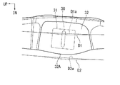
- FIG. 1 is an overall view showing an example of a center pillar arranged on a side portion of a vehicle such as an automobile.
- FIG. 2 is a cross-sectional view of the center pillar of FIG. 1 taken along the line II-II. It is the front view which looked at the top board part of the hinge reinforcement after the 2nd process (final form) from the vehicle outside.
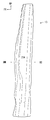
- FIG. 4 is a side view showing a vertical wall portion on a vehicle rear side when the hinge reinforcement shown in FIG. 3 is viewed from a direction of an arrow IV.
- FIG. 5 is a side view showing a vertical wall portion on a vehicle front side when the hinge reinforcement shown in FIG. 3 is viewed from a direction of an arrow V.
- FIG. 1 is an overall view showing an example of a center pillar arranged on a side portion of a vehicle such as an automobile.
- FIG. 2 is a cross-sectional view of the center pillar of FIG. 1 taken along the line II-II. It is the front view which looked at
- FIG. 6 is an enlarged view showing a plane portion for mounting a striker in the hinge reinforcement indicated by a circle VI in FIG. 5 in an enlarged manner. It is a perspective view which expands and shows the welding protrusion part formed in the vertical wall part of a hinge reinforcement. It is a key map showing the schematic structure of the draw forming process of hinge reinforcement. It is a conceptual diagram showing the schematic structure of the bending process of hinge reinforcement. It is sectional drawing which shows the state which attached the striker to the center pillar. It is the front view which looked at the top board part of the hinge reinforcement after the 1st process (after the drawing forming process) from the vehicle outside.
- FIG. 12 is a side view showing the vertical wall portion on the vehicle rear side when the hinge reinforcement shown in FIG. 11 is viewed from the direction of arrow XII.
- FIG. 13 is a side view showing the vertical wall portion on the vehicle front side when the hinge reinforcement shown in FIG. 11 is viewed from the direction of arrow XIII.
- the vehicle structural member is a center pillar, which is one of pillars installed on a side of a vehicle such as an automobile, and the reinforcing member is a hinge reinforcement for reinforcing the center pillar.
- the term regarding the direction used in the following description basically refers to a direction based on the vehicle in a normal posture.
- the arrow FR indicates the vehicle forward direction
- the arrow UP indicates the vehicle upward direction
- the arrow IN indicates the vehicle inside direction.
- FIG. 1 shows the appearance of a center pillar 10 for a vehicle such as an automobile
- FIG. 2 shows a cross section of the center pillar 10 of FIG. 1 taken along the line II-II.
- the center pillar 10 in FIG. 1 is on the left side of the vehicle.
- a front pillar (not shown) and a rear pillar (not shown) are arranged on the side of the vehicle as structural members for the vehicle.
- the strength of the center pillar 10 is particularly emphasized in view of a request for a side collision (side collision) of an automobile. Therefore, as shown in FIG. 2, a hinge reinforcement 20 is provided as a reinforcing member on the center pillar 10 to reinforce its strength.
- a high-strength steel plate is used as described later in response to a recent demand for higher strength.
- the center pillar 10 includes a long outer panel 12 that forms the outside of the vehicle and a long inner panel 14 that forms the inside of the vehicle.
- the center pillar 10 further includes a hinge reinforcement 20 disposed inside the outer panel 12.
- the outer panel 12 has a hat-shaped cross section that opens inward of the vehicle, and includes a top plate portion 12A, a vertical wall portion 12B, and a flange portion 12C.
- the top plate portion 12A is disposed on the outer side of the vehicle (lower side in FIG. 2), and a pair of left and right vertical wall portions 12B extend inward (upper side in FIG. 2) from both ends thereof.
- the pair of left and right vertical wall portions 12B are inclined in such a direction as to increase the space inward (upward in FIG. 2).
- the flange portions 12C extend in opposite directions from the inner (upper side in FIG. 2) ends of the pair of vertical wall portions 12B. Note that the flange portion 12C extends in the same direction as the top plate portion 12A.
- first vertical wall portion 12B and the first flange portion 12C which are arranged symmetrically, they are arranged on the vehicle rear side (right side) as viewed in FIG.
- members having the same reference numerals as those of the corresponding members and members provided on the front side (left side) of the vehicle are indicated with an f.
- the inner panel 14 is formed in a substantially flat plate shape, and a flange portion 14C extends outwardly from both side edges (right and left ends in FIG. 2) on the front and rear sides of the vehicle. Is out.
- the two flange portions 14C of the inner panel 14 are overlapped with the two flange portions 12C of the outer panel 12 in the vehicle width direction and joined by spot welding to form a closed cross section.
- welding points are indicated by black circles and in FIG. 2 by crosses. Further, the welding is not limited to spot welding, and may be performed by another method such as laser welding.
- the center pillar 10 is arranged to extend vertically in the vehicle.
- the center pillar 10 has a gently curved shape in which a central portion in the long direction protrudes outwardly.
- the center pillar 10 is inclined such that the upper end is located rearward of the vehicle from the lower end.
- the elongated center pillar 10 is formed in a closed cross-sectional structure, and forms one internal space inside.
- the center pillar 10 is joined to a roof side rail 18 via a substantially T-shaped mounting portion 16 formed at the upper end of the outer panel 12.
- the center pillar 10 is joined to the side sill 19 via a substantially T-shaped mounting portion 17 formed at the lower end of the outer panel 12.
- the outer panel 12 is a steel plate member having a tensile strength of 1180 MPa or more. In one embodiment, a 1470 MPa high tensile steel plate is used.
- the outer panel 12 is formed by a room temperature press, a cold press, or a hot stamp.
- the hinge reinforcement 20 arranged in the inner space of the center pillar 10 will be described. As shown in FIG. 2, the hinge reinforcement 20 is provided along the inner surface of the outer panel 12 of the center pillar 10.
- the hinge reinforcement 20 includes a top plate 20A and a vertical wall 20B.
- the hinge reinforcement 20 Since the hinge reinforcement 20 is disposed along the inner surface of the outer panel 12 of the center pillar 10 as described above, the hinge reinforcement 20 has a substantially U-shaped cross section.
- the top panel 20A is arranged inside the top panel 12A of the outer panel 12.
- the left and right vertical wall portions 20B as viewed in FIG. 2 are disposed inside the vertical wall portion 12B of the outer panel 12, and are directed inward (upward as viewed in FIG. 2) from the ridge lines L1 at both ends of the top plate portion 20A. It is formed integrally connected.
- the left and right vertical wall portions 20B are inclined in such a direction as to increase the interval inward (upward in FIG. 2).
- the vehicle rear side (the right side in FIG. 2).
- the members that are disposed at the front of the vehicle are denoted by the letter r
- the members that are disposed at the front side of the vehicle are denoted by the letter f.
- a front and rear door (not shown) of the vehicle is arranged before and after the center pillar 10 shown in FIG.
- a front door (front door) is arranged at the front of the center pillar 10
- a rear door (rear door) is arranged at the rear.
- the front door is opened and closed by a door hinge installed on the front pillar, and the front door is locked to the center pillar 10 by a striker 30 attached to the center pillar 10.
- the striker 30 is disposed below the front side of the center pillar 10 as shown in FIG.
- the striker 30 is illustrated as an image of the position of the striker 30 disposed on the vertical wall portions 12Bf and 20Bf on the front side. 2 is indicated by a two-dot chain line.
- FIG. 10 shows a specific configuration in which the striker 30 is disposed on the center pillar 10.
- the thickness of the outer panel 12, the inner panel 14, and the hinge reinforcement 20 is omitted.
- the striker 30 is disposed on the outer panel 12 and the vertical wall portions 12Bf, 20Bf on the front side of the hinge reinforcement 20.
- the striker mounting seat 31 is fixed and attached to the vertical wall portions 12Bf, 20Bf by fastening means 36 such as a bolt and a nut.
- the decorative plate 38 is provided outside the outer panel 12.
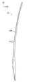
- FIGS. 3 to 5 show the overall structure of the hinge reinforcement 20.
- FIG. 3 is a view of the top plate portion 20A of the hinge reinforcement 20 as viewed from the outside.
- FIG. 4 shows a vertical wall portion 20Br on the vehicle rear side when the hinge reinforcement 20 of FIG. 3 is viewed from the direction of arrow IV.
- FIG. 5 shows the vertical wall portion 20Bf on the vehicle front side when the hinge reinforcement 20 shown in FIG. 3 is viewed from the direction of arrow V.
- the hinge reinforcement 20 is formed in a long shape, and is formed in a shape that is gently curved outward and convex as shown in FIGS. 4 and 5. I have.
- the hinge reinforcement 20 is formed by pressing. Then, in order to enhance the side collision performance, a high-tensile steel plate is used as a material for press forming. Its tensile strength is 980 MPa or more. In one embodiment, a high-strength steel plate of 1180 MPa is used. The thickness of the steel sheet is, for example, about 1 mm to 2 mm, and one high-tensile steel sheet is press-formed by a room temperature press, a cold press, or a hot stamp.
- the top plate 20A of the hinge reinforcement 20 is welded to the inner surface of the top plate 12A of the outer panel 12 of the center pillar 10 by spot welding. Is done. For this reason, a welding projection 22 for forming a welding seat surface 23 projects from the top plate 20A to the outside of the vehicle by a predetermined height.
- the welding protruding portions 22 are intermittently arranged along the vertical direction of the vehicle.
- the outer surface of the projection 22 for welding is formed in a flat shape as shown in FIG. 2 in order to secure the bonding strength between the outer panel 12 and the top plate 12A by spot welding.
- the shape of each of the welding protrusions 22 can be formed in a semicircle or a circle as one embodiment. However, as another embodiment, various shapes such as a rectangle, a triangle, an ellipse, and a hexagon can be used. You can also.
- the welding between the center pillar 10 and the hinge reinforcement 20 is also performed between the vertical wall portion 12B of the outer panel 12 and the vertical wall portion 20B of the hinge reinforcement 20, at the locations indicated by the crosses in FIG. ing. Therefore, a pair of vertical wall portions 20Br and 20Bf of the hinge reinforcement 20 shown in FIGS. 4 and 5 are provided with a welding projection 25 for forming a welding seat surface 26. However, in the pair of vertical wall portions 20Br and 20Bf shown in FIGS. 4 and 5, the welding protruding portion 25 is omitted.
- the welding projection 25 is formed so as to project toward the pair of vertical walls 12B of the outer panel 12, and is intermittently arranged in the vehicle vertical direction. And it is joined by spot welding to the inner surface of the vertical wall portion 12B at the welding seat surface 26 on the surface of the welding projection 25.
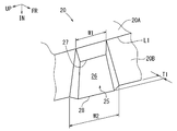
- FIG. 7 schematically shows the welding protrusion 25 formed on the vertical wall portion 20B of the hinge reinforcement 20.
- Each of the welding protrusions 25 projects from the vertical wall portion 20B to the outside of the hinge reinforcement 20 by a predetermined height T1.
- each welding protrusion 25 extends from each ridge line L1 formed between the pair of vertical wall portions 20B and the top plate portion 20A to the vehicle inner side of the vertical wall portion 20B. Project over the entire width up to the edge of the hinge reinforcement 20.
- Each of the welding protrusions 25 is formed in a trapezoidal shape in which the width W1 at the edge on the ridge line L1 side is smaller than the width W2 at the edge on the vehicle inward side, as viewed from the front.
- the edge of each welding protrusion 25 on the ridge line L1 side is chamfered diagonally toward the ridge line L1.
- each welding projection 25 that is, the welding seating surface 26 secures the bonding strength between the outer panel 12 and each vertical wall portion 12 ⁇ / b> B by spot welding. It is formed in a planar shape. Therefore, each welding seat surface 26 is flat from the edge 27 on each ridge line L1 side to the edge on the vehicle inward side of the vertical wall portion 20B, and the length of the edge 27 on the ridge line L1 side is long. It is formed in a trapezoidal shape that is narrower than the length of the edge 28 on the inner side of the vehicle and is turned sideways as viewed from the front.
- a flat surface portion 32 for attaching the striker 30 for locking the front door in a closed position is provided at a lower portion. Part is formed.
- the hatched portion in FIG. 5 is the plane portion 32 for mounting the striker.
- FIG. 6 shows the same portion in an enlarged manner. In FIG. 6, the position where the striker 30 is provided is indicated by a two-dot chain line.
- the striker 30 is attached to the outer panel 12 and the vertical wall portions 12B and 20B of the hinge reinforcement 20 via a striker mounting seat 31 having a flat plate shape to which the striker 30 is fixed. Therefore, it is required that the striker mounting flat portion 32 be formed in a flat shape without wrinkles.
- the flat portion 32 shown in FIG. 6 has a convex shape in which an edge 32A on the vehicle inward side projects toward the vehicle inward (downward in FIG. 6) by press molding.
- This convex shape is, for example, a smooth and gentle curved shape.
- the flat portion 32 is formed by press forming the hinge reinforcement 20.
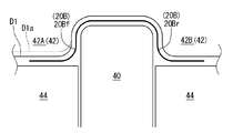
- FIGS. 8 and 9 show the arrangement of the forming dies in the draw forming step
- FIG. 9 shows the arrangement of the forming dies for performing the bending forming step.
- Each is for explaining press forming of the plane portion 32 in a cross section taken along line VII-VII in FIG.
- the pressing direction in the hinge reinforcement 20 is indicated by a white arrow P in FIGS. 4 and 5.
- FIG. 8 shows the draw forming step of the first step.
- the drawing die includes a fixed lower die 40, a movable upper die 42, and cushion dies 44 arranged on both sides of the lower die 40.
- the upper die 42 is integrally provided with a portion 42A for drawing and forming the front vertical wall portion 20Bf and a portion 42B for drawing and forming the rear vertical wall portion 20Br.
- the cushion mold 44 follows the movement of the upper mold 42 for drawing.
- the portion where the striker mounting flat portion 32 is formed corresponds to the above-described edge 32A on the front side in the pressing direction of the flat portion 32 described above. It has a convex shape.
- the vertical wall portion 20Bf has a smooth and gentle curved shape that swells forward in the pressing direction with respect to the die face that forms the portion adjacent to the flat portion 32 in the pressing direction.
- the dashed line D1a indicates the die face shape of the flat portion 32 that is not a normal convex shape.
- FIG. 8 also shows a normal die face position by a broken line. The fact that the die face has a convex shape means that the drawing depth at the flat portion 32 is deeper than the periphery.
- FIG. 9 shows the bending process of the second process.
- the bending mold includes a fixed lower mold 50, a movable upper mold 52, and a pad 54 for holding a press-formed product.
- the upper die 52 has an upper die 52A that bends the vertical wall 20Bf and an upper die 52B that bends the vertical wall 20Br.
- the pad 54 is for fixing the work (work) drawn and formed in the first step on the lower die 50, and performs bending while holding the work by the pad 54.
- the die face shape of the upper die 52A for bending and forming the vertical wall portion 20Bf is set to the same shape as the die face shape of the portion 42A for forming the vertical wall portion 20Bf of the upper die 42 in the above-described drawing. That is, the die face shape of the upper mold 52A is set to the shape shown by the solid line D2 in FIGS. Also in the bending in the second step, the die face of the upper die 52A for forming the plane portion 32 for attaching the striker has a convex shape corresponding to the edge 32A of the plane portion 32 on the front side in the pressing direction.
- the vertical wall portion 20Bf has a smooth and gentle curved shape that swells forward in the pressing direction with respect to the die face that forms the portion adjacent to the flat portion 32 in the pressing direction.
- the normal die face position is indicated by a broken line D2a as in the case of the draw forming in the first step.
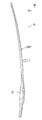
- FIGS. 11 to 13 show the shape of the hinge reinforcement 20 in the middle of forming after the drawing forming step of the first step.
- the final form of the hinge reinforcement 20 after the bending step of the second step is the form shown in FIGS. 3 to 5 described above.
- FIG. 11 is a view showing a top plate portion 20A of the hinge reinforcement 20 as viewed from the outside of the vehicle.
- FIG. 12 shows a vertical wall portion 20Br on the vehicle rear side when the hinge reinforcement 20 of FIG. 11 is viewed from the direction of arrow XII.
- FIG. 11 is a view showing a top plate portion 20A of the hinge reinforcement 20 as viewed from the outside of the vehicle.
- FIG. 12 shows a vertical wall portion 20Br on the vehicle rear side when the hinge reinforcement 20 of FIG. 11 is viewed from the direction of arrow XII.
- FIG. 13 shows a vertical wall portion 20Bf on the vehicle front side when the hinge reinforcement 20 shown in FIG. 11 is viewed from the direction of arrow XIII.
- the pressing direction is indicated by a white arrow P.
- Press forming of the hinge reinforcement 20 is performed by pressing in the direction of arrow P.
- the illustration of the welding protrusions 22 and 25 in FIGS. 11 to 13 is omitted as in FIGS. 3 to 5.
- FIG. 9 showing the bending process in the second step, a two-dot chain line indicates a cross section of the vertical wall portion 20B of the hinge reinforcement 20 (FIGS. 11 to 13) after the drawing process in the first step shown in FIG.
- the shape is shown. From this shape, as shown by an arrow in FIG. 9, it is pressed into a solid line shape by an upper mold 52 for bending.
- the plane portion 32 for mounting the striker formed on the vertical wall portion 20Bf on the front side of the vehicle is press formed.
- the shape is convex toward the pressing direction.
- the forming of the edge on the front side in the pressing direction is formed by pressing from the center of the convex shape to both sides. Migrate and be eliminated.
- the surface forming portion does not have surface undulation. That is, the occurrence of wrinkles due to surface undulation is prevented or suppressed.
- press forming is performed in two steps of drawing and bending. Therefore, a locus of the shock line is formed on the processed product (work) formed by the drawing forming process. The shock line is not erased by the subsequent bending, but does not affect the flatness.
- the vehicle structural member is the center pillar, and the reinforcing member is a hinge reinforcement therefor.
- another pillar and a reinforcing member therefor may be used.
- structural members for vehicles other than pillars and structural members for vehicles therefor may be used.
- the other components attached to the vertical wall portion of the hinge reinforcement of the reinforcing member are strikers for locking the vehicle door.
- components other than the strikers may be used.
- the other components are arranged on the vertical wall on one side of the hinge reinforcement, as another embodiment, they may be arranged on the vertical walls on both sides.
- the press forming of the hinge reinforcement was performed in two steps of drawing and bending, but as another embodiment, it may be performed in one step, or may be performed in three or more steps. You may.
- a flat portion for attaching another vehicle component is formed on the vertical wall portion of the reinforcing member, and the flat portion is an end on the front side in the pressing direction when the reinforcing member is press-formed.
- the edge has a curved shape that is convex in the pressing direction.
- the vehicle structural member is a pillar installed on the side of the vehicle, and the reinforcing member is a hinge reinforcement for reinforcing the pillar.
- the flat part for attaching other components to the hinge reinforcement can have a flat shape in which the generation of wrinkles is prevented or suppressed. Therefore, the configuration of the pillar member reinforced by the hinge reinforcement can be made with high accuracy.
- the other vehicle component is a striker for locking a vehicle door, and the striker is attached to a plane portion.
- the striker flat portion can be formed into a flat shape in which generation of wrinkles is prevented or suppressed, and the striker can be attached with high accuracy.
- the reinforcing member is manufactured by press molding using a press mold
- the press mold includes a first die face corresponding to the flat portion of the vertical wall portion and a first die face adjacent to the flat portion of the vertical wall portion. And a second die face corresponding to the portion to be formed, and the first die face has a curved shape that is more convex in the pressing direction than the second die face.
- the press forming is performed in a step of drawing the reinforcing member by a drawing die and a step of bending the drawn reinforcing member by a bending die.
- Each of the bending dies has a first die face having the above-mentioned convex curved shape.
Landscapes
- Engineering & Computer Science (AREA)
- Mechanical Engineering (AREA)
- Chemical & Material Sciences (AREA)
- Combustion & Propulsion (AREA)
- Transportation (AREA)
- Physics & Mathematics (AREA)
- Optics & Photonics (AREA)
- Plasma & Fusion (AREA)
- Quality & Reliability (AREA)
- Body Structure For Vehicles (AREA)
- Shaping Metal By Deep-Drawing, Or The Like (AREA)
Abstract
L'invention concerne un élément de renforcement pour élément structural pour véhicule, comprenant une plaque supérieure et une paire de parois verticales qui s'étendent depuis les deux bords de la plaque supérieure. Une partie plate destinée à fixer un autre élément structural pour véhicule est formée sur au moins une des deux parois verticales et la partie plate est formée de telle sorte que le bord sur la face avant dans la direction de pression lors du moulage à la presse de l'élément de renforcement ait une forme incurvée faisant saillie dans la direction de pression.
Priority Applications (2)
| Application Number | Priority Date | Filing Date | Title |
|---|---|---|---|
| US17/257,790 US11840280B2 (en) | 2018-07-04 | 2019-06-28 | Reinforcement for a vehicle structural member and method for manufacturing the same |
| CN201980044220.5A CN112437704B (zh) | 2018-07-04 | 2019-06-28 | 用于车辆用构造部件的加强部件及其制造方法 |
Applications Claiming Priority (2)
| Application Number | Priority Date | Filing Date | Title |
|---|---|---|---|
| JP2018-127705 | 2018-07-04 | ||
| JP2018127705A JP6991935B2 (ja) | 2018-07-04 | 2018-07-04 | 車両用補強部材とその製造法 |
Publications (1)
| Publication Number | Publication Date |
|---|---|
| WO2020009034A1 true WO2020009034A1 (fr) | 2020-01-09 |
Family
ID=69059521
Family Applications (1)
| Application Number | Title | Priority Date | Filing Date |
|---|---|---|---|
| PCT/JP2019/025876 Ceased WO2020009034A1 (fr) | 2018-07-04 | 2019-06-28 | Élément de renforcement pour élément structural pour véhicule et son procédé de production |
Country Status (4)
| Country | Link |
|---|---|
| US (1) | US11840280B2 (fr) |
| JP (1) | JP6991935B2 (fr) |
| CN (1) | CN112437704B (fr) |
| WO (1) | WO2020009034A1 (fr) |
Citations (4)
| Publication number | Priority date | Publication date | Assignee | Title |
|---|---|---|---|---|
| JPH0260681U (fr) * | 1988-10-27 | 1990-05-07 | ||
| JP2013220807A (ja) * | 2012-04-19 | 2013-10-28 | Toyota Motor Corp | 車体側部構造 |
| JP2014024467A (ja) * | 2012-07-27 | 2014-02-06 | Mazda Motor Corp | 車両の車体側部構造 |
| JP2017197191A (ja) * | 2017-08-09 | 2017-11-02 | トヨタ自動車株式会社 | 車両用骨格構造 |
Family Cites Families (16)
| Publication number | Priority date | Publication date | Assignee | Title |
|---|---|---|---|---|
| JP3498615B2 (ja) * | 1999-01-29 | 2004-02-16 | マツダ株式会社 | 車両の車体構造及びその製造方法 |
| JP3833874B2 (ja) * | 2000-05-10 | 2006-10-18 | 三菱自動車工業株式会社 | 車体部材 |
| JP4497736B2 (ja) | 2001-03-02 | 2010-07-07 | 本田技研工業株式会社 | 2枚重ね製品の成形用ブランク材 |
| JP2004100215A (ja) * | 2002-09-06 | 2004-04-02 | Honda Motor Co Ltd | 車両用取付部品取付構造 |
| JP4736905B2 (ja) * | 2006-03-31 | 2011-07-27 | トヨタ自動車株式会社 | 車両のセンターピラー補強構造 |
| CN201343063Y (zh) * | 2008-12-25 | 2009-11-11 | 比亚迪股份有限公司 | 一种汽车b柱 |
| JP2011088596A (ja) * | 2009-10-26 | 2011-05-06 | Mazda Motor Corp | 車両の車体構成部材 |
| JP5593813B2 (ja) * | 2010-04-28 | 2014-09-24 | スズキ株式会社 | 車体補強構造 |
| JP2012218691A (ja) * | 2011-04-13 | 2012-11-12 | Suzuki Motor Corp | 車体後部構造 |
| JP5935360B2 (ja) * | 2012-02-01 | 2016-06-15 | マツダ株式会社 | 車両用フレーム構造 |
| JP5614514B2 (ja) * | 2012-09-27 | 2014-10-29 | 新日鐵住金株式会社 | センターピラーリンフォースメントの製造方法 |
| CN104903020B (zh) | 2013-01-07 | 2016-12-21 | 新日铁住金株式会社 | 冲压成型品的制造方法 |
| JP2015066584A (ja) | 2013-09-30 | 2015-04-13 | 株式会社ヒロテック | プレス成形方法及びプレス成形金型 |
| JP6449562B2 (ja) * | 2014-06-13 | 2019-01-09 | トヨタ自動車株式会社 | 車両用骨格構造 |
| CN204956647U (zh) * | 2015-07-22 | 2016-01-13 | 北汽福田汽车股份有限公司 | 用于车辆的b柱及具有其的车辆 |
| CN106608287B (zh) * | 2016-12-05 | 2020-01-14 | 杭州都凌汽车研发有限公司 | 一种汽车b柱加强板总成 |
-
2018
- 2018-07-04 JP JP2018127705A patent/JP6991935B2/ja active Active
-
2019
- 2019-06-28 WO PCT/JP2019/025876 patent/WO2020009034A1/fr not_active Ceased
- 2019-06-28 US US17/257,790 patent/US11840280B2/en active Active
- 2019-06-28 CN CN201980044220.5A patent/CN112437704B/zh active Active
Patent Citations (4)
| Publication number | Priority date | Publication date | Assignee | Title |
|---|---|---|---|---|
| JPH0260681U (fr) * | 1988-10-27 | 1990-05-07 | ||
| JP2013220807A (ja) * | 2012-04-19 | 2013-10-28 | Toyota Motor Corp | 車体側部構造 |
| JP2014024467A (ja) * | 2012-07-27 | 2014-02-06 | Mazda Motor Corp | 車両の車体側部構造 |
| JP2017197191A (ja) * | 2017-08-09 | 2017-11-02 | トヨタ自動車株式会社 | 車両用骨格構造 |
Also Published As
| Publication number | Publication date |
|---|---|
| US11840280B2 (en) | 2023-12-12 |
| JP6991935B2 (ja) | 2022-01-13 |
| US20220219759A1 (en) | 2022-07-14 |
| CN112437704A (zh) | 2021-03-02 |
| CN112437704B (zh) | 2023-02-03 |
| JP2020006756A (ja) | 2020-01-16 |
Similar Documents
| Publication | Publication Date | Title |
|---|---|---|
| JP6921909B2 (ja) | パネル状成形品 | |
| CN105188980B (zh) | 冲压成形部件的制造方法以及冲压成形装置 | |
| EP3501684B1 (fr) | Composant formé à la presse de carrosserie automobile et son procédé de fabrication | |
| CN104684661B (zh) | 中柱加强件的制造方法 | |
| US20180185899A1 (en) | Method and apparatus for manufacturing press component | |
| CN112703130B (zh) | 具有钢加强件的保险杠梁 | |
| CN104080691B (zh) | 车辆用车架构造 | |
| JP7163270B2 (ja) | センターピラーリインフォースメント | |
| WO2020009033A1 (fr) | Élément de renforcement d'un élément structural d'un véhicule | |
| JP3870351B2 (ja) | 自動車用バンパービームおよびその製造方法 | |
| US11884331B2 (en) | Center pillar manufacturing method | |
| JP7399905B2 (ja) | プレス型及びプレス成形品 | |
| JP2019064493A (ja) | 車両の車体側部の上部アーチ構造 | |
| JP4932688B2 (ja) | 自動車車体用ルーフ補強材 | |
| WO2020009034A1 (fr) | Élément de renforcement pour élément structural pour véhicule et son procédé de production | |
| JP6665612B2 (ja) | プレス成形品の製造方法及びプレス装置 | |
| US12508644B2 (en) | Vehicle center pillar member and method for manufacturing same | |
| JP6705280B2 (ja) | 構造体及びその製造方法 | |
| JP7604321B2 (ja) | 車両用プレス部品の製造方法 | |
| JP6196921B2 (ja) | プレス部品の製造方法 | |
| JP7084159B2 (ja) | 車両のドアビーム | |
| US20240317315A1 (en) | Vehicle-body lower structure | |
| JP4042139B2 (ja) | 自動車の車体構造部材 | |
| JP2026011814A (ja) | 自動車車体用の骨格部材、継ぎ手構造及び骨格部材の製造方法 | |
| JP2020185848A (ja) | 車両の側面上部構造 |
Legal Events
| Date | Code | Title | Description |
|---|---|---|---|
| 121 | Ep: the epo has been informed by wipo that ep was designated in this application |
Ref document number: 19830752 Country of ref document: EP Kind code of ref document: A1 |
|
| NENP | Non-entry into the national phase |
Ref country code: DE |
|
| 122 | Ep: pct application non-entry in european phase |
Ref document number: 19830752 Country of ref document: EP Kind code of ref document: A1 |