WO2020009033A1 - Élément de renforcement d'un élément structural d'un véhicule - Google Patents
Élément de renforcement d'un élément structural d'un véhicule Download PDFInfo
- Publication number
- WO2020009033A1 WO2020009033A1 PCT/JP2019/025867 JP2019025867W WO2020009033A1 WO 2020009033 A1 WO2020009033 A1 WO 2020009033A1 JP 2019025867 W JP2019025867 W JP 2019025867W WO 2020009033 A1 WO2020009033 A1 WO 2020009033A1
- Authority
- WO
- WIPO (PCT)
- Prior art keywords
- welding
- vertical wall
- wall portion
- vehicle
- bead
- Prior art date
- Legal status (The legal status is an assumption and is not a legal conclusion. Google has not performed a legal analysis and makes no representation as to the accuracy of the status listed.)
- Ceased
Links
Images



Classifications
-
- B—PERFORMING OPERATIONS; TRANSPORTING
- B62—LAND VEHICLES FOR TRAVELLING OTHERWISE THAN ON RAILS
- B62D—MOTOR VEHICLES; TRAILERS
- B62D25/00—Superstructure or monocoque structure sub-units; Parts or details thereof not otherwise provided for
- B62D25/04—Door pillars ; windshield pillars
-
- B—PERFORMING OPERATIONS; TRANSPORTING
- B23—MACHINE TOOLS; METAL-WORKING NOT OTHERWISE PROVIDED FOR
- B23K—SOLDERING OR UNSOLDERING; WELDING; CLADDING OR PLATING BY SOLDERING OR WELDING; CUTTING BY APPLYING HEAT LOCALLY, e.g. FLAME CUTTING; WORKING BY LASER BEAM
- B23K26/00—Working by laser beam, e.g. welding, cutting or boring
- B23K26/20—Bonding
- B23K26/21—Bonding by welding
- B23K26/22—Spot welding
-
- B—PERFORMING OPERATIONS; TRANSPORTING
- B62—LAND VEHICLES FOR TRAVELLING OTHERWISE THAN ON RAILS
- B62D—MOTOR VEHICLES; TRAILERS
- B62D21/00—Understructures, i.e. chassis frame on which a vehicle body may be mounted
- B62D21/15—Understructures, i.e. chassis frame on which a vehicle body may be mounted having impact absorbing means, e.g. a frame designed to permanently or temporarily change shape or dimension upon impact with another body
- B62D21/157—Understructures, i.e. chassis frame on which a vehicle body may be mounted having impact absorbing means, e.g. a frame designed to permanently or temporarily change shape or dimension upon impact with another body for side impacts
-
- B—PERFORMING OPERATIONS; TRANSPORTING
- B21—MECHANICAL METAL-WORKING WITHOUT ESSENTIALLY REMOVING MATERIAL; PUNCHING METAL
- B21D—WORKING OR PROCESSING OF SHEET METAL OR METAL TUBES, RODS OR PROFILES WITHOUT ESSENTIALLY REMOVING MATERIAL; PUNCHING METAL
- B21D22/00—Shaping without cutting, by stamping, spinning, or deep-drawing
- B21D22/20—Deep-drawing
- B21D22/26—Deep-drawing for making peculiarly, e.g. irregularly, shaped articles
-
- B—PERFORMING OPERATIONS; TRANSPORTING
- B21—MECHANICAL METAL-WORKING WITHOUT ESSENTIALLY REMOVING MATERIAL; PUNCHING METAL
- B21D—WORKING OR PROCESSING OF SHEET METAL OR METAL TUBES, RODS OR PROFILES WITHOUT ESSENTIALLY REMOVING MATERIAL; PUNCHING METAL
- B21D53/00—Making other particular articles
- B21D53/88—Making other particular articles other parts for vehicles, e.g. cowlings, mudguards
Definitions
- the present invention relates to a reinforcing member for a structural member for a vehicle.
- pillars are provided as structural members on the side of vehicles such as automobiles.
- the pillars include a front pillar generally called an A pillar, a center pillar commonly called a B pillar, and a rear pillar commonly called a C pillar from the front of the automobile.
- the center pillar is particularly required to have structural strength in order to cope with a side collision (side collision) of an automobile. Therefore, the center pillar is provided with a reinforcing member called a hinge reinforcement to reinforce its strength.
- the center pillar is formed in a closed cross section by an outer panel having a long hat-shaped cross section and a flat inner panel.
- the center pillar is reinforced by arranging a hinge reinforcement in the closed cross section and joining the hinge reinforcement to the outer panel by welding or the like.
- the hinge reinforcement Since the hinge reinforcement is disposed within the closed cross section of the center pillar, the hinge reinforcement has a U-shaped cross section corresponding to the inner surface shape of the outer panel having a hat-shaped cross section, and is formed in an elongated shape.
- the U-shaped cross section is formed of a top plate at the center in the width direction and a pair of vertical wall portions that are bent from the ridge lines at both ends in the width direction of the top plate and extend.
- the center pillar and the hinge reinforcement are partially curved in the longitudinal direction, and are arranged so as to curve outward of the vehicle.
- the molding of the hinge reinforcement of the reinforcing member is performed by pressing.
- One steel plate is bent by a press to form a U-shaped cross section (see Japanese Patent Application Laid-Open No. 2010-115674).
- the material of the hinge reinforcement tends to increase the material strength due to the recent demand for the improvement of the side collision performance.
- a high-strength material is used in press molding, it is difficult to crush and flatten a wrinkle (wrinkle) on the molding once generated in the press molding process. That is, when the material strength is not high, even if wrinkles are formed during the forming process, the wrinkles can be crushed at the last press forming of the forming to form a planar shape.
- a high-strength material it is considered that once a wrinkle is formed, it is difficult to break the wrinkle in a subsequent press molding process because of the high strength. Furthermore, it is troublesome and difficult to remove wrinkles by other means after press molding.
- wrinkles at the time of press molding are likely to occur on the vertical wall portion of the curved portion in the U-shaped hinge reinforcement. Since the hinge reinforcement is welded to the center pillar at the vertical wall portion, it is required to form the vertical wall portion accurately without wrinkles.
- the wrinkle in question means an out-of-plane undulation generated in the steel sheet.
- One aspect of the present invention is a reinforcing member for a structural member for a vehicle, which is disposed in an internal space of the structural member for a vehicle having a closed cross section and is joined to the structural member for a vehicle by welding. It has a curved portion in at least a part of the longitudinal direction, has a top plate portion, and a pair of vertical wall portions extending from ridge lines at both ends of the top plate portion, and is formed in a U-shaped cross section.
- the vertical wall portion includes a plurality of welding protrusions having a seating surface for welding at intervals in a longitudinal direction, and the welding protrusion is provided for the vehicle from a base surface of the vertical wall portion.
- a bead Projecting toward a structural member, a bead is formed between the welding protrusions on the vertical wall portion of the curved portion to prevent or suppress wrinkles during press forming, and the bead is
- the vertical wall projects from the base surface toward the vehicle structural member. It is.
- the height of the bead from the base surface is formed lower than the height of the welding protrusion from the base surface.
- the bead and the welding protrusion are arranged at intervals such that the curved transition from the bead to the base surface and the curved transition from the welding protrusion to the base surface do not overlap.
- the bead extends from the opening edge of the vertical wall toward the ridge, and has a length less than the width of the vertical wall.
- the height of the welding protrusion disposed on the curved portion of the vertical wall portion from the base surface at the ridge line is zero, and the height from the base surface toward the seat surface increases. ing.
- FIG. 1 is an overall view showing an example of a center pillar arranged on a side portion of a vehicle such as an automobile.
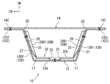
- FIG. 2 is a cross-sectional view of the center pillar of FIG. 1 taken along the line II-II. It is the front view which looked at the top board part of the hinge reinforcement from the vehicle inside.
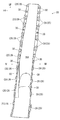
- FIG. 4 is a side view showing a vertical wall portion on a vehicle rear side when the hinge reinforcement shown in FIG. 3 is viewed from a direction of an arrow IV.
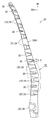
- FIG. 5 is a side view showing a vertical wall portion on a vehicle front side when the hinge reinforcement shown in FIG. 3 is viewed from a direction of an arrow V.
- FIG. 5 is an enlarged perspective view showing a region VI in the hinge reinforcement of FIG. 4.
- FIG. 4 is a side view showing a vertical wall portion on a vehicle rear side when the hinge reinforcement shown in FIG. 3 is viewed from a direction of an arrow IV.
- FIG. 5 is a side view showing a vertical
- FIG. 7 is an enlarged perspective view showing a welding protrusion in the hinge reinforcement of FIG. 6. It is the figure which looked at the connection state of the welding projection part of the vertical wall part of a hinge reinforcement and the wrinkle removal bead toward the edge, omits thickness, and is exaggeratingly expressing height.
- the vehicle structural member of the present embodiment is a center pillar of a pillar member installed on a side portion of a vehicle such as an automobile, and the reinforcing member is a hinge reinforcement for reinforcing the center pillar.
- the direction display appropriately shown in each drawing indicates a direction in a normal posture state of a vehicle such as an automobile, an arrow FR indicates a vehicle forward direction, an arrow UP indicates a vehicle upward direction, and an arrow IN indicates a vehicle inward direction in a vehicle width direction. . In the following description, the description regarding the direction is based on this direction.
- FIG. 1 shows a schematic configuration of a center pillar 10 for a vehicle such as an automobile
- FIG. 2 shows a cross section of the center pillar 10 of FIG. 1 taken along the line II-II.
- the center pillar 10 of FIG. 1 shows a configuration installed on the left side in the traveling direction of a vehicle such as an automobile.
- a pillar member is provided as a vehicle structural member on the side of a vehicle such as an automobile.
- the pillar members include a front pillar (not shown) commonly called an A pillar, a center pillar 10 commonly called a B pillar, and a rear pillar (not shown) commonly called a C pillar from the front of the automobile.
- the strength of the center pillar 10 is regarded as important in view of a demand for a side collision (side collision) of an automobile. Therefore, as shown in FIG. 2, the center pillar 10 is provided with a reinforcing member called a hinge reinforcement 20 for reinforcing its strength.
- a high-strength steel plate is used as described later in response to a demand for higher strength in recent years.
- the center pillar 10 has a long outer panel 12 that forms the vehicle outside of the center pillar 10 and a long outer panel 12 that forms the vehicle inside of the center pillar 10. And an inner panel 14. And it further comprises a hinge reinforcement 20 disposed inside the outer panel 12.
- the outer panel 12 is formed in a hat-shaped cross-sectional shape that opens toward the inside of the vehicle, and includes a top plate 12A, a vertical wall 12B, and a flange 12C.
- the top plate portion 12A is disposed on the outer side of the vehicle (the lower side in FIG. 2), and a pair of left and right vertical wall portions 12B is provided from the ridge lines at both ends toward the outer side of the vehicle (the upper side in FIG. 2). Is extending.
- the arrangement of the pair of left and right vertical wall portions 12B is formed so as to be inclined in such a direction as to increase the interval toward the inside of the vehicle (upward in FIG. 2).
- the flange portions 12C integrally extend in opposite directions from ends of the pair of vertical wall portions 12B on the vehicle inner side (upper side in FIG. 2).
- the arrangement direction of the flange portion 12C is the same as the arrangement direction of the top plate portion 12A.
- the members disposed on the vehicle rear side include the members.
- the symbol r is added after the symbol, and the members disposed on the front side of the vehicle (the left side in FIG. 2) are indicated with f.
- the inner panel 14 is formed in a substantially flat plate shape, and a flange portion 14C extends outward from both ends on the front and rear sides of the vehicle (left and right ends in FIG. 2). .
- the two flange portions 14C of the inner panel 14 are overlapped with the two flange portions 12C of the outer panel 12 in the vehicle width direction and joined by spot welding to form a closed cross section.
- welding points are indicated by black circles and in FIG. 2 by crosses.
- the welding is not limited to spot welding, but may be performed by other welding such as laser welding.
- the elongated center pillar 10 is disposed so as to extend in the vertical direction of the vehicle. And it has a gentle curved shape protruding outward from the vehicle at a position slightly below the longitudinal center.
- the center pillar 10 is inclined such that the upper end is located rearward of the vehicle from the lower end.
- the elongated center pillar 10 is formed in a closed cross-sectional structure, and forms one internal space inside.
- the center pillar 10 is joined to the roof side rail 18 via a substantially T-shaped mounting portion 16 formed at the upper end of the outer panel 12.
- the center pillar 10 is joined to the side sill 19 via a substantially T-shaped mounting portion 17 formed at the lower end of the outer panel 12.
- the outer panel 12 is a steel plate member having a tensile strength of, for example, 1180 MPa or more. As one embodiment, a 1470 MPa high tensile steel plate can be used. The outer panel 12 is formed by a room temperature press, a cold press, or a hot stamp. As the inner panel 14, a steel plate member having a tensile strength equal to or lower than the tensile strength of the outer panel 12 is used. As one embodiment, a 590 MPa steel plate member can be used. Then, the inner panel 14 is formed by a room temperature press.
- the hinge reinforcement 20 arranged in the inner space of the center pillar 10 will be described. As shown in FIG. 2, the hinge reinforcement 20 is provided along the inner surface of the outer panel 12 of the center pillar 10.
- the hinge reinforcement 20 includes a top plate 20A and a vertical wall 20B.
- the hinge reinforcement 20 Since the hinge reinforcement 20 is disposed along the inner surface of the outer panel 12 of the center pillar 10 as described above, the hinge reinforcement 20 has a substantially U-shaped cross section.
- the top panel 20A of the hinge reinforcement 20 is arranged inside the top panel 12A of the outer panel 12.
- the two vertical wall portions 20B are arranged inside the vertical wall portion 12B, and extend integrally from the ridge lines L1 at both ends of the top plate portion 20A toward the inside of the vehicle (upward in FIG. 2).
- the left and right vertical wall portions 20B are inclined in such a direction as to increase the interval toward the inside of the vehicle (upward in FIG. 2).
- the U-shaped cross section of the hinge reinforcement 20 includes the top plate portion 20A at the center in the width direction and the pair of vertical wall portions 20B extending from the ridge lines at both ends in the width direction of the top plate portion 20A. Formed.
- the vehicle rear side (the right side in FIG. 2).
- members with the letter r after the reference numerals and members arranged on the front side of the vehicle (the left side in FIG. 2) are given the letter f.
- FIGS. 3 to 5 show the overall structure of the hinge reinforcement 20.
- FIG. FIG. 3 shows a state in which the top plate portion 20A of the hinge reinforcement 20 is viewed from the inside of the vehicle.
- FIG. 4 shows a vertical wall portion 20Br on the vehicle rear side when the hinge reinforcement 20 of FIG. 3 is viewed from the direction of arrow IV.
- FIG. 5 shows the vertical wall portion 20Bf on the vehicle front side when the hinge reinforcement 20 shown in FIG. 3 is viewed from the direction of arrow V.
- the hinge reinforcement 20 is formed in an elongated shape, and is gently curved outward of the vehicle as shown in FIGS. That is, the hinge reinforcement 20 has a curved portion in a partial range in the longitudinal direction.
- the region VI is a curved portion.
- the hinge reinforcement 20 is formed by press molding. Then, in order to enhance the side collision performance, a high-tensile steel plate is used as a material for press forming. Its tensile strength is usually 980 MPa or more. As one embodiment, a high-strength steel plate of 1180 MPa can be used.
- the thickness of the pressed steel sheet can be, for example, about 1 mm to 2 mm, and one high-tensile steel sheet is formed by a room temperature press, a cold press, or a hot stamp.
- the direction indicated by a white arrow P in FIGS. 4 and 5 is the pressing direction.
- the vertical wall portion 20B subjected to the bending process has excess thickness, and wrinkles are likely to occur. In particular, wrinkles are likely to occur on the vertical wall portion 20B of the curved portion of the hinge reinforcement 20.
- the top plate 20A of the hinge reinforcement 20 is joined to the inner surface of the top plate 12A of the outer panel 12 by spot welding. You. For this reason, a plurality of welding protrusions 22 for forming a welding seat surface 23 project from the top plate portion 20A of the hinge reinforcement 20 to a predetermined height (for example, 2 mm) outward in the vehicle width direction. Each welding protrusion 22 is intermittently arranged along the vehicle up-down direction.
- the outer surface of the projection 22 for welding is formed in a flat shape as shown in FIG. 2 in order to secure the bonding strength between the outer panel 12 and the top plate 12A by spot welding. ing.
- the shape of each welding projection 22 is not clear in FIG. 2, it can be formed as a semicircle or a circle as one embodiment. However, in other embodiments, the shape may be various shapes such as a rectangle, a triangle, an ellipse, and a hexagon.
- the center pillar 10 and the hinge reinforcement 20 are also welded between the vertical wall portion 12B of the outer panel 12 and the vertical wall portion 20B of the hinge reinforcement 20 at locations indicated by the crosses in FIG. Therefore, a plurality of welding protrusions 25 for forming a welding seat surface 26 are formed on the pair of vertical wall portions 20Br and 20Bf of the hinge reinforcement 20 shown in FIGS. 4 and 5.
- Each welding protruding portion 25 protrudes toward a pair of vertical wall portions 12B of the outer panel 12, and is intermittently arranged in the vehicle up-down direction. Then, the welding seat surface 26 is joined to the inner surface of the vertical wall portion 12B of the outer panel 12 by spot welding.
- FIG. 6 is an enlarged view of the vertical wall portion 20Br in the region VI in FIG. 4 described above, which is the curved portion of the hinge reinforcement 20. Note that the vertical wall portion 20Bf of the region VI in FIG. 5 at a symmetrical position has the same configuration.
- welding projections 25 and wrinkle removing beads 30 are alternately formed on the vertical wall portion 20 ⁇ / b> B of the curved portion of the hinge reinforcement 20.
- the welding projections 25 are formed at intervals over the entire range in the longitudinal direction, but in the curved range, each wrinkle removing bead 30 is disposed between the two welding projections 25. ing.
- the welding protrusion 25 serves to provide a welding place between the outer panel 12 and the hinge reinforcement 20 as described above, and also reduces wrinkles generated in the vertical wall portion 20B when the hinge reinforcement 20 is press-formed. It acts to prevent or suppress the occurrence.
- the wrinkle-removing bead 30 is provided solely for the purpose of preventing or suppressing the generation of wrinkles generated during press molding. For this reason, the wrinkle removing bead 30 is disposed in a curved portion where wrinkles are likely to occur during press molding.
- FIGS. 7 and 8 are diagrams schematically showing the welding protrusion 25 formed on the vertical wall portion 20B of the hinge reinforcement 20.
- FIG. 8 is a view of the vertical wall portion 20B as viewed toward the edge, in which the thickness is omitted and the height is exaggerated.
- the welding protrusion 25 extends from a ridge line L1 formed between the vertical wall portion 20B and the top plate portion 20A to an edge of the vertical wall portion 20B on the vehicle inward side. Projecting outward over the entire width of.
- the welding protruding portion 25 is formed in a trapezoidal shape in which the width W1 at the edge on the ridge line L1 side is narrower than the width W2 at the edge on the vehicle inward side, as viewed from the front.
- the surface of the welding protruding portion 25 is composed of an inclined surface portion 29 on the ridge line L1 side and a welding seat surface 26 on the edge 28 side.
- the boundary 27 between the inclined surface portion 29 and the welding seat surface 26 is indicated by a line.
- the inclined surface portion 29 on the ridge line L1 side of the welding projection 25 is formed so as to lift the welding seat surface 26. That is, the height of the inclined surface portion 29 from the base surface 32 gradually increases toward the boundary 27 with the welding seat surface 26, with the height at the ridge line L1 being zero. Thereby, it is possible to prevent cracks caused by sheet sink during press forming.
- the welding seat surface 26 is formed in a planar shape as shown in FIGS. 2 and 7 in order to secure the joining strength between the outer panel 12 and the vertical wall portion 12B by spot welding. Accordingly, the welding seat surface 26 is flat from the boundary 27 with the inclined surface portion 29 to the edge 28 of the vertical wall portion 20B on the vehicle inward side, and the width at the boundary 27 is on the vehicle inward side. It is formed in a trapezoidal shape that is narrower than the width at the edge 28 and that is sideways when viewed from the front.
- the wrinkle removing bead 30 of the hinge reinforcement 20 will be described. As shown in FIG. 6, the wrinkle bead 30 is formed between two adjacent welding protrusions 25 of the hinge reinforcement 20 as described above. The position where the wrinkle removing bead 30 is formed is a curved portion of the vertical wall portion 20B. It can be said that the wrinkle removing bead 30 is basically a structure in which the above-mentioned welding protruding portion 25 is miniaturized.
- the wrinkle removing bead 30 is formed in a mountain shape as shown in FIG. 8, and is formed to protrude from the base surface 32 of the vertical wall portion 20B in the same direction as the protruding direction of the welding protruding portion 25. That is, the wrinkle removing bead 30 protrudes toward the inner surface of the vertical wall portion 12B of the center pillar 10.
- the height T2 of the wrinkle removing bead 30 from the base surface 32 is formed to be lower than the projection height T1 of the welding projection 25.
- the protrusion height T2 of the wrinkle-removing bead 30 is formed to be lower than the protrusion height T1 of the welding protrusion 25, the top of the wrinkle-removing bead 30 may come into contact with the inner surface of the vertical wall portion 12B of the outer panel 12. Absent. Thereby, generation of abnormal noise can be prevented. For example, if the wrinkle-removing bead 30 of the hinge reinforcement 20 and the inner surface of the vertical wall portion 12B of the outer panel 12 come into contact with each other, noise may be generated due to the contact while the vehicle is running. can do.
- the wrinkle-removing bead 30 extends from the edge 28 on the opening side of the vertical wall portion 20B of the hinge reinforcement 20 toward the ridgeline L1 in the width direction of the vertical wall portion 20B (the vertical direction as viewed in FIG. 6). ), But is shorter than the width of the vertical wall portion 20B. That is, the length does not reach the ridge line L1. Then, the wrinkle removing bead 30 has a mountain shape in which the height from the base surface 32 is reduced and the width is reduced as approaching the ridge line L1. This is because the shrinkage deformation of the vertical wall portion 20B in the press forming is larger on the vehicle inner side (lower portion) than on the vehicle outer side (upper portion in FIG. 6). Wrinkles during press molding are caused by excess wall thickness due to shrinkage deformation, and therefore, the shape is adapted to this.
- the interval width between the adjacent welding protrusions 25 can be arranged closer. Thereby, the number of the welding protrusions 25 can be increased as necessary.
- the welding projection 25 and the wrinkle removing bead 30 of the hinge reinforcement 20 are both formed in a mountain shape or a table shape, and the inclined wall shapes 25K and 30K are used to form the vertical wall portion. It is connected to the base surface 32 of 20B.
- the inclined surfaces 25K and 30K and the base surface 32 of the vertical wall portion 20B are connected by curved R portions 25R and 30R (curved transition portions).
- the wrinkle-removing bead 30 and the welding protruding portion 25 are arranged at intervals such that the R portion 30R of the wrinkle-removing bead 30 does not overlap with the R portion 25R of the welding protruding portion 25.
- the R portion 30R of the wrinkle removing bead 30 and the R portion 25R of the welding protrusion 25 can be continuous without an interval. This is a configuration based on the request for disposing the adjacent welding protrusions 25 close to each other as described above.
- the R portion 30 ⁇ / b> R of the wrinkle removing bead 30 and the R portion 25 ⁇ / b> R of the welding protrusion 25 may be separated by the base surface 32.
- the occurrence of wrinkles is effectively prevented while securing the necessary collision performance strength. Or can be suppressed.
- the R portion 30R of the wrinkle removing bead 30 and the R portion 25R of the welding protrusion 25 do not shift to the base surface 32 of the vertical wall portion 20B, and the two R portions 30R and 25R overlap. To be connected.
- the projections 25 for welding formed on the vertical wall portion 20B of the hinge reinforcement 20 and the wrinkle removing beads 30 prevent or suppress the generation of wrinkles generated in the vertical wall portion 20B during press forming. can do. In the case of press-forming using a high-tensile steel sheet, the generation of wrinkles can be particularly effectively prevented or suppressed.
- a plurality of welding protrusions 25 are formed on the vertical wall portion 20 ⁇ / b> B of the hinge reinforcement 20 at appropriate intervals over the entire elongated region. Accordingly, the welding projection 25 first serves to provide a welding seat surface 26 so as to be welded and fixed to the inner surface of the vertical wall portion 12B of the outer panel 12, as described above.
- the welding protrusion 25 of the hinge reinforcement 20 is formed by welding the extra thickness in the longitudinal direction generated on the base surface 32 of the vertical wall portion 20B in the left-right direction. It absorbs by contracting and deforming in the longitudinal direction (the left and right direction as viewed in FIGS. 6 to 8). This makes it possible to prevent or suppress wrinkles in the excess thickness during press molding.
- the wrinkle removing bead 30 is provided in the curved portion.
- the wrinkle removing bead 30 is provided between the projections 25 for welding of the vertical wall portion 20B in the curved portion.
- the excess thickness generated in the curved portion is absorbed by the wrinkle removing bead 30 together with the welding protruding portion 25, and the occurrence of wrinkles is prevented or suppressed.
- the wrinkle-removing bead 30 also contracts and deforms in the longitudinal direction of the hinge reinforcement 20 to absorb the excess thickness.
- the portion of the vertical wall portion 20B in the curved portion that is outside the curved portion is elongated, and the portion that is inside the curved portion is contracted. Since the excess thickness at the time of press molding is generated by the shrinkage action, wrinkles are more likely to occur on the inner side of the curve. For this reason, it is necessary to absorb more excess material toward the inner side of the curve.
- the wrinkle removing bead 30 has a shape corresponding to this tendency to shrink, so that it is possible to effectively remove wrinkles. it can. For example, as shown in FIG. 6, the width of the top of the wrinkle removing bead 30 gradually decreases from the edge of the vertical wall portion 20 ⁇ / b> B in the curved portion toward the ridge line.
- the longitudinal compressive strain of the vertical wall portion 20B was 0.14 at the maximum in the hinge reinforcement without the wrinkle removing bead, whereas the hinge reinforcement with the wrinkle removing bead 30 was used. At 20 the maximum was 0.12, a 14% improvement.
- the amount of springback at the time of press forming of the vertical wall portion 20B was 4.56 mm in the present embodiment, compared with 5.16 mm in the conventional configuration, which is an improvement of 11%.
- the number of wrinkle removing beads 30 provided between the welding projections 25 of the vertical wall portion 20B described above is not limited to one, and may be two or more as another embodiment. What is necessary is just to determine according to the curvature of the curved part in the vertical wall part 20B in which the wrinkle removal bead 30 is provided.
- the wrinkle-removing bead 30 is effectively formed at the curved portion of the hinge reinforcement 20, but may be provided at another portion, if necessary, as another embodiment.
- the wrinkle removing bead 30 is not limited to a mountain shape or a table shape having a top as shown in the figure, but as another embodiment, the base surface can be contracted and deformed, such as an inverted V-shape, and the wrinkle removing bead can be removed. Any shape can be used as long as it can be formed.
- a high-strength material is used as the material of the hinge reinforcement 20 from the viewpoint of the side collision performance.
- this feature can be applied to a reinforcing member that requires wrinkling at the time of press molding, regardless of the material strength, as another embodiment.
- the vehicle structural member is the center pillar 10 and the reinforcing member is the hinge reinforcement 20 for reinforcing the Ceuta pillar 10, but as another embodiment, other pillar members and A reinforcing member for that purpose may be used. As another embodiment, a vehicle structural member other than the pillar member and a reinforcing member therefor may be used.
- the vertical wall portion is provided with a plurality of welding protrusions having seats for welding at intervals in the longitudinal direction, and the welding protrusion is provided on the base surface of the vertical wall portion. From the vehicle toward the vehicle structural member. For this reason, first, the excess thickness of the base surface of the vertical wall portion at the time of press forming is absorbed by the welding projection, and the generation of wrinkles generated in the vertical wall portion can be prevented or suppressed.
- a bead that prevents or suppresses the generation of wrinkles during press forming is formed on the vertical wall portion of the curved portion between the welding protrusions, and the bead is formed at the base of the vertical wall portion. From the surface toward the vehicle structural member.
- This curved portion is a portion where wrinkles easily occur during press molding.
- the welding protrusion and the wrinkle-removing bead absorb the excess thickness of the curved portion where the wrinkle is likely to occur, thereby reliably preventing or suppressing the generation of the wrinkle in the curved portion.
- the vertical wall portion can be formed with high accuracy, and the reinforcing member can be formed.
- the height of the bead from the base surface is formed lower than the height of the welding protrusion from the base surface.
- the bead and the welding protrusion are arranged at such an interval that the curved transition from the bead to the base surface and the curved transition from the welding protrusion to the base surface do not overlap. I have. This makes it possible to effectively prevent or suppress the occurrence of wrinkles while securing the required collision performance strength.
- the bead extends from the edge on the opening side of the vertical wall toward the ridge, and its length is smaller than the width of the vertical wall. This makes it possible to reduce the interval between adjacent welding protrusions.
- the height of the welding protrusion disposed on the curved portion of the vertical wall portion from the base surface at the ridge line is zero, and the height from the base surface toward the seat surface is zero. Is getting bigger. Thereby, it is possible to prevent cracks caused by sheet sink during press forming.
Landscapes
- Engineering & Computer Science (AREA)
- Mechanical Engineering (AREA)
- Chemical & Material Sciences (AREA)
- Combustion & Propulsion (AREA)
- Transportation (AREA)
- Physics & Mathematics (AREA)
- Optics & Photonics (AREA)
- Plasma & Fusion (AREA)
- Body Structure For Vehicles (AREA)
- Shaping Metal By Deep-Drawing, Or The Like (AREA)
Abstract
L'invention concerne un élément de renforcement pour un élément structural pour un véhicule. L'élément de renforcement est positionné dans l'espace interne d'un élément structural pour un véhicule présentant une section transversale fermée, est joint par soudage à l'élément structural pour un véhicule, présente une portion incurvée dans au moins une partie dans la direction longitudinale, présente une plaque supérieure, et une paire de parois verticales qui s'étendent à partir des lignes de crête sur les deux bords de la plaque supérieure, et est formé en une forme rectangulaire à extrémité ouverte. Les parois verticales sont pourvues d'une pluralité de saillies pour le soudage, présentant une surface de support pour le soudage à des intervalles lorsqu'elles sont vues dans la direction longitudinale. Les saillies pour le soudage font saillie à partir de la surface de base des parois verticales vers l'élément structural pour un véhicule, et un cordon de soudure qui empêche ou réduit l'apparition de rides pendant le moulage à la presse est formé sur les parois verticales dans la partie incurvée, entre les saillies pour le soudage. Le cordon de soudure fait saillie à partir de la surface de base des parois verticales vers l'élément structural pour un véhicule.
Priority Applications (3)
| Application Number | Priority Date | Filing Date | Title |
|---|---|---|---|
| US17/257,006 US11970213B2 (en) | 2018-07-02 | 2019-06-28 | Reinforcement for a vehicle structural member |
| CN201980044516.7A CN112839748B (zh) | 2018-07-02 | 2019-06-28 | 用于车辆用结构部件的加强部件 |
| EP19831259.7A EP3819039B1 (fr) | 2018-07-02 | 2019-06-28 | Élément de renforcement d'un élément structural d'un véhicule |
Applications Claiming Priority (2)
| Application Number | Priority Date | Filing Date | Title |
|---|---|---|---|
| JP2018-125840 | 2018-07-02 | ||
| JP2018125840A JP6995708B2 (ja) | 2018-07-02 | 2018-07-02 | 車両用補強部材 |
Publications (1)
| Publication Number | Publication Date |
|---|---|
| WO2020009033A1 true WO2020009033A1 (fr) | 2020-01-09 |
Family
ID=69060942
Family Applications (1)
| Application Number | Title | Priority Date | Filing Date |
|---|---|---|---|
| PCT/JP2019/025867 Ceased WO2020009033A1 (fr) | 2018-07-02 | 2019-06-28 | Élément de renforcement d'un élément structural d'un véhicule |
Country Status (5)
| Country | Link |
|---|---|
| US (1) | US11970213B2 (fr) |
| EP (1) | EP3819039B1 (fr) |
| JP (1) | JP6995708B2 (fr) |
| CN (1) | CN112839748B (fr) |
| WO (1) | WO2020009033A1 (fr) |
Families Citing this family (5)
| Publication number | Priority date | Publication date | Assignee | Title |
|---|---|---|---|---|
| KR102492993B1 (ko) * | 2020-11-18 | 2023-01-30 | 주식회사 포스코 | 차량용 사이드멤버 |
| JP7399905B2 (ja) * | 2021-03-31 | 2023-12-18 | 豊田鉄工株式会社 | プレス型及びプレス成形品 |
| JP7621213B2 (ja) * | 2021-07-14 | 2025-01-24 | トヨタ紡織株式会社 | 形状凍結性に優れた自動車シート用部品の製造方法 |
| CN114954666A (zh) * | 2022-06-14 | 2022-08-30 | 合肥长安汽车有限公司 | 一种a柱加强件的上铰链加强结构及其制造方法 |
| JP7726158B2 (ja) * | 2022-09-01 | 2025-08-20 | トヨタ自動車株式会社 | 板金部材成形方法 |
Citations (5)
| Publication number | Priority date | Publication date | Assignee | Title |
|---|---|---|---|---|
| JPH10218017A (ja) | 1997-01-31 | 1998-08-18 | Nissan Motor Co Ltd | センターピラーの補強構造 |
| JP2010115674A (ja) | 2008-11-12 | 2010-05-27 | Nippon Steel Corp | プレス加工方法及びプレス成形体 |
| JP2013220807A (ja) * | 2012-04-19 | 2013-10-28 | Toyota Motor Corp | 車体側部構造 |
| JP5614514B2 (ja) * | 2012-09-27 | 2014-10-29 | 新日鐵住金株式会社 | センターピラーリンフォースメントの製造方法 |
| JP2017197191A (ja) * | 2017-08-09 | 2017-11-02 | トヨタ自動車株式会社 | 車両用骨格構造 |
Family Cites Families (7)
| Publication number | Priority date | Publication date | Assignee | Title |
|---|---|---|---|---|
| JP3335781B2 (ja) * | 1994-08-31 | 2002-10-21 | 富士重工業株式会社 | 車両のセンタピラー部全周閉断面構造 |
| CN202827763U (zh) * | 2012-07-11 | 2013-03-27 | 东风汽车公司 | 一种乘用车b柱结构 |
| JP6106982B2 (ja) * | 2012-07-27 | 2017-04-05 | マツダ株式会社 | 車両の車体側部構造 |
| JP6449562B2 (ja) * | 2014-06-13 | 2019-01-09 | トヨタ自動車株式会社 | 車両用骨格構造 |
| JP6211496B2 (ja) * | 2014-09-19 | 2017-10-11 | 豊田鉄工株式会社 | 車両用構造部材およびその製造方法 |
| JP6135699B2 (ja) * | 2015-03-11 | 2017-05-31 | トヨタ自動車株式会社 | 車両側部構造 |
| CN107554616B (zh) * | 2017-07-20 | 2019-07-19 | 宝沃汽车(中国)有限公司 | C柱加强板及车辆 |
-
2018
- 2018-07-02 JP JP2018125840A patent/JP6995708B2/ja active Active
-
2019
- 2019-06-28 WO PCT/JP2019/025867 patent/WO2020009033A1/fr not_active Ceased
- 2019-06-28 US US17/257,006 patent/US11970213B2/en active Active
- 2019-06-28 CN CN201980044516.7A patent/CN112839748B/zh active Active
- 2019-06-28 EP EP19831259.7A patent/EP3819039B1/fr active Active
Patent Citations (5)
| Publication number | Priority date | Publication date | Assignee | Title |
|---|---|---|---|---|
| JPH10218017A (ja) | 1997-01-31 | 1998-08-18 | Nissan Motor Co Ltd | センターピラーの補強構造 |
| JP2010115674A (ja) | 2008-11-12 | 2010-05-27 | Nippon Steel Corp | プレス加工方法及びプレス成形体 |
| JP2013220807A (ja) * | 2012-04-19 | 2013-10-28 | Toyota Motor Corp | 車体側部構造 |
| JP5614514B2 (ja) * | 2012-09-27 | 2014-10-29 | 新日鐵住金株式会社 | センターピラーリンフォースメントの製造方法 |
| JP2017197191A (ja) * | 2017-08-09 | 2017-11-02 | トヨタ自動車株式会社 | 車両用骨格構造 |
Non-Patent Citations (1)
| Title |
|---|
| See also references of EP3819039A4 |
Also Published As
| Publication number | Publication date |
|---|---|
| EP3819039A1 (fr) | 2021-05-12 |
| JP6995708B2 (ja) | 2022-01-17 |
| CN112839748A (zh) | 2021-05-25 |
| EP3819039A4 (fr) | 2022-03-23 |
| US11970213B2 (en) | 2024-04-30 |
| EP3819039B1 (fr) | 2024-11-13 |
| JP2020001653A (ja) | 2020-01-09 |
| US20210178445A1 (en) | 2021-06-17 |
| CN112839748B (zh) | 2023-04-28 |
Similar Documents
| Publication | Publication Date | Title |
|---|---|---|
| WO2020009033A1 (fr) | Élément de renforcement d'un élément structural d'un véhicule | |
| CN101835674B (zh) | 车辆侧部结构 | |
| US8091318B2 (en) | Formed part for vehicle body structural member | |
| CN113490617B (zh) | 车辆用构造构件 | |
| CN109969264B (zh) | 车身部件的制造方法及车辆的车身部件 | |
| CN107428380A (zh) | 车身构造 | |
| JP6713497B2 (ja) | 車両用センタピラー | |
| CN116056956B (zh) | 汽车车身构造部件 | |
| CN111433112B (zh) | 车辆用加强部件和车辆用中柱 | |
| JP7399905B2 (ja) | プレス型及びプレス成形品 | |
| US12508644B2 (en) | Vehicle center pillar member and method for manufacturing same | |
| JP5237252B2 (ja) | 自動車のバンパー構造体 | |
| JP2008284934A (ja) | 自動車のドアガードバー | |
| JP2009184527A (ja) | ピラー補強構造 | |
| JP6176046B2 (ja) | 高張力鋼板製の溶接構造体 | |
| JP2023146031A (ja) | 車体フレーム構造 | |
| JP6991935B2 (ja) | 車両用補強部材とその製造法 | |
| JP2026011814A (ja) | 自動車車体用の骨格部材、継ぎ手構造及び骨格部材の製造方法 | |
| JPH11277156A (ja) | プレス成形方法 | |
| WO2022025105A1 (fr) | Élément structural de carrosserie de véhicule | |
| JP2024011264A (ja) | プレス成形方法 | |
| JP2022083895A (ja) | 車両用フレーム部材 | |
| JP2022124879A (ja) | 車体フレームおよび車体フレームの製造方法 | |
| JP2019188865A (ja) | 車両のセンタピラー |
Legal Events
| Date | Code | Title | Description |
|---|---|---|---|
| 121 | Ep: the epo has been informed by wipo that ep was designated in this application |
Ref document number: 19831259 Country of ref document: EP Kind code of ref document: A1 |
|
| NENP | Non-entry into the national phase |
Ref country code: DE |
|
| ENP | Entry into the national phase |
Ref document number: 2019831259 Country of ref document: EP Effective date: 20210202 |