WO2020009035A1 - Marqueur - Google Patents
Marqueur Download PDFInfo
- Publication number
- WO2020009035A1 WO2020009035A1 PCT/JP2019/025891 JP2019025891W WO2020009035A1 WO 2020009035 A1 WO2020009035 A1 WO 2020009035A1 JP 2019025891 W JP2019025891 W JP 2019025891W WO 2020009035 A1 WO2020009035 A1 WO 2020009035A1
- Authority
- WO
- WIPO (PCT)
- Prior art keywords
- lens
- marker
- lens unit
- portions
- detected
- Prior art date
- Legal status (The legal status is an assumption and is not a legal conclusion. Google has not performed a legal analysis and makes no representation as to the accuracy of the status listed.)
- Ceased
Links
Images

Classifications
-
- G—PHYSICS
- G01—MEASURING; TESTING
- G01B—MEASURING LENGTH, THICKNESS OR SIMILAR LINEAR DIMENSIONS; MEASURING ANGLES; MEASURING AREAS; MEASURING IRREGULARITIES OF SURFACES OR CONTOURS
- G01B11/00—Measuring arrangements characterised by the use of optical techniques
-
- G—PHYSICS
- G02—OPTICS
- G02B—OPTICAL ELEMENTS, SYSTEMS OR APPARATUS
- G02B3/00—Simple or compound lenses
-
- G—PHYSICS
- G02—OPTICS
- G02B—OPTICAL ELEMENTS, SYSTEMS OR APPARATUS
- G02B3/00—Simple or compound lenses
- G02B3/02—Simple or compound lenses with non-spherical faces
- G02B3/04—Simple or compound lenses with non-spherical faces with continuous faces that are rotationally symmetrical but deviate from a true sphere, e.g. so called "aspheric" lenses
-
- G—PHYSICS
- G02—OPTICS
- G02B—OPTICAL ELEMENTS, SYSTEMS OR APPARATUS
- G02B3/00—Simple or compound lenses
- G02B3/02—Simple or compound lenses with non-spherical faces
- G02B3/06—Simple or compound lenses with non-spherical faces with cylindrical or toric faces
-
- G—PHYSICS
- G01—MEASURING; TESTING
- G01B—MEASURING LENGTH, THICKNESS OR SIMILAR LINEAR DIMENSIONS; MEASURING ANGLES; MEASURING AREAS; MEASURING IRREGULARITIES OF SURFACES OR CONTOURS
- G01B11/00—Measuring arrangements characterised by the use of optical techniques
- G01B11/26—Measuring arrangements characterised by the use of optical techniques for measuring angles or tapers; for testing the alignment of axes
Definitions
- the present invention relates to a marker.
- AR Augmented Reality
- visual markers are used to recognize the position and orientation of an object.
- the marker for example, a marker in which a lenticular lens is arranged on a black stripe pattern has been reported (Patent Document 1).
- the lenticular lens is generally a lens body in which cylindrical lenses obtained by dividing a cylinder in the axial direction are continuously arranged so that the axial directions are parallel to each other.
- a cylindrical lens also referred to as a lens portion
- a convex portion extending in the axial direction is such that the axial direction thereof is parallel to the black line direction of the stripe pattern, and the pitch is the pitch of the stripe pattern.
- the pitch is the pitch of the stripe pattern.
- the marker when the marker is visually recognized by a camera or the like from the convex side of the lenticular lens, the image of the striped pattern projected on the lenticular lens is detected by being moved or deformed according to the visual direction. You. For this reason, the visual recognition direction can be known from the detected image, and the position and orientation of the object can be recognized as described above.
- each lens portion of the marker aberration may occur due to the inclination of the optical axis of the incident light, and the image of the detected portion may not be able to appear clearly.
- the marker of the present invention comprises: Including the lens body,
- the lens body is On one surface side, it has a plurality of lens parts arranged continuously, On the other surface side, it is detectable from the one surface side, and has a plurality of detected parts corresponding to each of the lens units, The pitch of the plurality of lens portions and the pitch of the plurality of detected portions are different,
- the plurality of lens units Each has a convex portion on the one surface side, An arbitrary lens portion is used as a reference lens portion, and in the continuous arrangement direction of the plurality of lens portions, each of the convex portions is relatively large from the reference lens portion toward the end of the lens body. It has a center radius of curvature.
- the marker of the present invention reduces the influence of aberration at each lens portion due to the inclination of the optical axis of the incident light by changing the center radius of curvature of the convex portion of each lens portion as described above.
- the image from the detection unit can be made to appear clearly, and the detection accuracy of the marker can be improved.
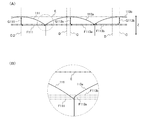
- FIG. 1A is a top view illustrating an example of a lens body of the marker according to the first embodiment
- FIG. 1B is a cross-sectional view of the marker as viewed from the II direction in FIG.
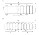
- FIG. 2A is a cross-sectional view illustrating a part of the lens surface of the marker according to the first embodiment
- FIG. 2B is an enlarged view of a region surrounded by a circle in FIG.
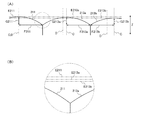
- FIG. 3A is a top view of the lens body of the marker according to the second embodiment
- FIG. 3B is a cross-sectional view of the marker as viewed from the II-II direction in FIG. 3A.
- FIG. 4A is a cross-sectional view illustrating a part of the lens surface of the marker according to the second embodiment
- FIG. 4B is an enlarged view of a region surrounded by a circle in FIG.
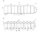
- FIG. 5A is a top view of the lens body of the marker according to the third embodiment
- FIG. 5B is a cross-sectional view of the marker as viewed from the III-III direction in FIG. 5A.
- the center axis of the detected part of the reference lens unit is located at the center axis of the convex part of the reference lens unit.
- each of the plurality of lens portions has the same width of the convex portion in a continuous arrangement direction of the plurality of lenses.
- the apex of the central axis of the convex portion is located at the same height in the lens body.
- At least one end of the convex portion is in contact with the end of the convex portion of the adjacent lens portion.
- the convex portion is arranged from the reference lens portion toward the end of the lens body. Have a relatively large width.
- the lens body is a lenticular lens in which cylindrical lenses are continuously arranged in one direction as the lens unit.
- the lens body is a lens array in which the lens units are continuously arranged in two intersecting directions.
- the lens body is an integrally molded product.
- Embodiment 1 is an example of the marker of the present invention.
- FIG. 1 shows an example of the marker according to the present embodiment.
- FIG. 1A is a top view of the marker 1
- FIG. 1B is a cross-sectional view of the marker 1 as seen from the II direction in FIG. 1A.
- a hatch representing a cross section is omitted for easy viewing.
- arrow X is referred to as a width direction
- arrow Y is referred to as a length direction
- arrow Z is referred to as a thickness direction.
- a dotted line C in the Z direction indicates a central axis of each lens unit, and the central axis is an axis in the thickness direction Z passing through the center in the width direction X in each lens unit.
- a dotted line D in the Z direction indicates a central axis of the detected part 200, and the central axis is an axis in the thickness direction Z passing through the center in the width direction X in each detected part.
- the marker 1 includes a lens body 10.
- the lens main body 10 has a plurality of lens portions continuously arranged in a planar direction on one surface side, that is, on the upper surface side in FIG. 1B, and the plurality of lens portions are respectively provided on the one side.
- the lens body 10 has a plurality of detected portions that can be detected from the one surface side on the other surface side, that is, the lower surface side in FIG. 1B, and correspond to each lens portion.
- the marker of the present invention is characterized in that, for each of the plurality of lens portions, each convex portion has a central radius of curvature as described below, so that light is condensed on each corresponding detected portion, Other configurations are not limited at all.
- the plurality of lens units are continuously arranged in the X direction (that is, the width direction).
- the arrangement direction of the plurality of lens units will be described as the width direction X
- the direction perpendicular to the continuous arrangement direction will be described as the thickness direction Z.
- the plurality of lens units include a lens unit at an arbitrary position as a reference lens unit 111, and an upstream lens unit group 112 that is continuously arranged upstream of the reference lens unit 111. And a downstream lens unit group 113 continuously arranged on the downstream side.
- the reference lens unit 111, the upstream lens unit group 112, and the downstream lens unit group 113 form a lens surface 11 on one surface side of the lens body 10.
- the reference lens unit 111 has an apex on the central axis C and has the corresponding detection target 200, so that the optical axis of the incident light coaxial with the central axis C ( 0 °), and the lens portions 112a and 113a, the lens portions 112b and 113b, the lens portions 112c and 113c, and the lens portions 112d and 113d each have an optical axis (incident light) inclined from the central axis C by a predetermined angle. For example, a lens for 5 °, 10 °, 15 °, and 20 °).
- each convex portion is an optical function portion.
- the optical function unit means transmitting or refracting and condensing light arriving from the outside.
- the convex portion has, for example, an entire surface having an aspheric convex shape having a curvature, for example.
- each of the convex portions of the plurality of lens portions has, for example, an aspherical shape that is bilaterally symmetric with respect to the central axis C, and the vertex is on the central axis C.
- the center radius of curvature of each of the protrusions can be represented by, for example, the radius of curvature of the vertex.
- the term “symmetric” includes, for example, a shape that is completely the same and, for example, substantially the same meaning as long as the same function is performed.
- Each of the convex portions has, for example, a radius of curvature increases from an apex thereof to an adjacent lens portion, and the radius of curvature may increase continuously, for example, or may increase intermittently. .
- each of the convex portions has a relatively large center as it moves from the reference lens portion 111 toward the end of the lens body 10 in the X direction, that is, as the distance from the reference lens portion 111 increases. It has a radius of curvature.
- the upstream lens unit group 112 includes the lens units 112a, 112b, 112c, and 112d from the reference lens unit 111 toward the upstream end of the lens body 10; The center radius of curvature of each convex portion is set to be relatively large toward 112d.
- the downstream lens unit group 113 includes the lens units 113a, 113b, 113c, and 113d from the reference lens unit 111 toward the downstream end of the lens body 10, and the lens unit 113 extends from the reference lens unit 111 to the lens unit 113d.
- the center radius of curvature of each projection is set to be relatively large.
- the marker 1 is configured such that each of the convex portions of the plurality of lens portions has the above-described center radius of curvature, so that, for each of the following reasons, in each of the lens portions, for example, the influence of aberration or the like is reduced.
- the image of the detected portion 200 can be displayed and detected with better accuracy.
- the present inventor has found that when the center radius of curvature of each lens portion is uniform, the more the optical axis of the incident light is inclined from the center axis C, the more the focus position varies, so that the center radius of curvature of each lens portion is uniform. I noticed that there is.
- the uniform radius of curvature of the center of each lens unit means that the focal length of each lens unit is constant regardless of the inclination of the optical axis of the incident light. Therefore, as the optical axis of the incident light is inclined from the central axis C, the central curvature radius is set to be relatively large with respect to the corresponding convex portion of each lens unit, so that the focal length is relatively increased. As a result, they have found that even if the optical axis of the incident light is inclined, the influence of aberration can be reduced.
- the center radius of curvature of the convex portion of the reference lens unit 111 and the degree of change of the center radius of curvature based on the center radius are not particularly limited.
- the center radius of curvature of the projection of the reference lens unit 111 is, for example, in the range of 0.1 to 1 mm.
- the change in the center radius of curvature of each protrusion in the upstream lens unit group 112 and the change in the center radius of curvature of each protrusion in the downstream lens unit group 113 are the same. It may be a change or a different change.
- the upstream lens portion 112a and the downstream lens portion 113a have the same center radius of curvature
- the lens portion 112b and the lens portion have the same center radius of curvature.
- the change in the center radius of curvature of the upstream lens unit group 112 may be larger or smaller than the change in the center radius of curvature of the downstream lens unit group 113.
- the overall shape of the upstream lens unit group 112 and the overall shape of the downstream lens unit group 113 may be symmetric or asymmetric.
- the upstream lens portion 112a and the downstream lens portion 113a which are symmetrical with respect to the reference lens portion 111, the lens portion 112b and the lens portion 113b,
- the lens portions 112c and 113c, and the lens portions 112d and 113d have symmetric shapes, respectively. Therefore, in the case of FIG. 1B, the overall shape of the upstream lens unit group 112 and the overall shape of the downstream lens unit group 113 are symmetric.
- the term “symmetric” includes, for example, a shape that is completely the same and, for example, substantially the same meaning as long as the same function is performed.
- the number of the lens portions in the lens body 10 is nine, but this is an example, and the present invention is not limited to this.
- the number of the lens units is an even number
- the number of the reference lens units 111 may be two.
- the number of lens units in the upstream lens unit group 112 and the number of lens units in the downstream lens unit group 113 may be the same or different, for example.
- the number of lens portions in the lens body 10 is not particularly limited, and is, for example, 221 pieces, 101 pieces, and 51 pieces.
- the lens body 10 may be, for example, one in which cylindrical lenses are continuously arranged in one direction as the lens portion, and is also referred to as a lenticular lens.
- the size of each lens unit is not particularly limited, and can be determined as appropriate according to, for example, the number of the lens units, the use of the marker 1, and the like.
- Each lens portion has a length in the length direction Y of, for example, 25 mm and 5 mm, and a length (thickness) passing through the central axis C in the thickness direction Z is, for example, 1.7 mm, 1 mm, and 0.6 mm. is there.
- the length W1 in the width direction X is, for example, 0.65 mm, 0.5 mm, or 0.37 mm, which can also be referred to as a pitch (P1) of the lens unit described later.
- the pitch (P1) of each of the lens portions that is, the length in the width direction X is uniform, and the apex of each of the lens portions, that is, the apex of each of the convex portions is the same. It is an example of height. The present invention is not limited to this example, and other examples will be described later.
- FIG. 2A a part of the lens surface 11 in FIG. 1B is shown in a cross-sectional view of FIG. 2A, and an enlarged view of a circled area in FIG. ).
- reference numeral E denotes a line connecting the vertices of the lens units.
- the vertices of the lens units have the same height.
- the lens body 10 of the present embodiment is an example in which the length W1 of the lens units in the width direction X is uniform.
- the distance between the lens portions (for example, the reference lens portion 111 and the lens portion 113a is changed) due to the change in the center radius of curvature.
- This step can be represented, for example, by the difference (sag difference) between the sag of one lens unit and the sag of the other lens unit.
- “sag” can be represented by, for example, a difference between the coordinates of the vertex and the coordinates of the maximum radius of the convex portion in the Z direction. Specifically, in FIG.
- a difference G111 between the coordinates of the vertex of the reference lens unit 111 and the coordinates of the maximum radius F111 of the reference lens unit 111 is the sag of the reference lens unit 111
- the difference G113a between the coordinates of the vertex of the lens 113a and the coordinates of the maximum radius F113a of the lens 113a is the sag of the lens 113a
- the difference G113b is the sag of the lens unit 113b.
- the sag difference between the reference lens unit 111 and the lens unit 113a can be obtained, for example, by “coordinate of F111 ⁇ the coordinate of F113a”, and the sag difference between the lens unit 113a and the lens unit 113b is, for example, “F113a Coordinates-coordinates of F113b ".
- the sag difference between the lens units may change from the reference lens unit 111 toward the upstream end and from the reference lens unit 111 toward the downstream end, or may be the same. Good.
- the pitch of the plurality of lens units means a pitch P1 between adjacent lens units in the width direction X.
- the “pitch P1 between adjacent lens units” is an interval between the center points of the widths W1 of the lens units in the adjacent lens units, and is, for example, the same as the width W1 of the lens units in the width direction X.
- the pitch P1 of each lens unit of the upstream lens unit group 112, the reference lens unit 111, and each lens unit of the downstream lens unit group 113 may be the same or different, for example, and the marker 1 in FIG.
- each of the lens units has an equal pitch.
- the lens body 10 can be detected from the one surface side on the other surface side, that is, the lower surface side in FIG. 1B, and a plurality of lenses corresponding to the respective lens units can be detected. It has a detection unit 200.
- the detected portion 200 is a line extending along the length direction Y of the lens body 10, and a plurality of lines form a striped pattern.
- the plurality of detected parts 200 are projected on the upper surface side of the lens body 10 as optically detectable images, for example, and can be optically detected.
- the shape of the detected portion in the present invention is not limited to this, and the shape of the detected portion 200 may be, for example, a shape in which points (dots) are aligned in the length direction Y.
- the pitch of the plurality of detected portions 200 is different from the pitch P1 of the plurality of lens portions.
- the pitch of the plurality of detected parts 200 means a pitch P2 between the detected parts 200 adjacent in the width direction X.
- the “pitch between adjacent detection units” is, for example, a distance between centers of adjacent detection units 200 in the width direction X.
- the pitch P2 can be determined based on, for example, the relationship between the center position of each lens unit and the corresponding center position of each detected part. Specifically, for example, it can be determined as follows. First, the center position (center axis C) of the reference lens unit 111 is matched with the center position (center axis D) of the detection target 200 corresponding to the reference lens unit 111.
- the upstream lens group 112 and the downstream lens group 113 move away from the reference lens unit 111, that is, how many (n) the lens units are adjacent to the reference lens unit 111.
- the distance between the center position of the lens unit (center axis C) and the corresponding center position of the detection target 200 (center axis D) can be set to be wide.
- the immediately upstream lens portion and the downstream lens portion each have a center position (center axis C) and a corresponding center position (center axis) of the detected portion 200 by a distance ⁇ ⁇ n (n ⁇ 2).
- the axis D) can be set to be shifted.
- ⁇ is, for example, any positive number (hereinafter the same).
- the center of the detected part 200 is, for example, a midpoint in the width direction X and a midpoint in the length direction Y, and is a point through which the central axis D passes.
- the pitches P2 of the plurality of detected portions 200 may be the same or different, for example, and the marker 1 in FIG. 1 is an example in which the lens portions have the same pitch.
- the pitch P1 of the lens units may be larger than the pitch P2 of the detection unit 200, or may be smaller than the pitch P2 of the detection unit 200.
- the width W2 of the detected portion 200 in the width direction X is not particularly limited, and is, for example, 45 ⁇ m, 30 ⁇ m, or 10 ⁇ m.
- the width of the detected part 200 can be appropriately determined, for example, according to the pitch P1 between the adjacent lens parts.
- the ratio of the width W2 of the detected portion 200 to the pitch P1 between the lens portions is, for example, 1: 200 to 1: 5.
- the marker 1 has, for example, an apex of the reference lens unit 111 on the central axis C of the reference lens unit 111, and has a detected part 200 corresponding to the reference lens unit 111. Therefore, when the marker 1 is observed from, for example, a direction directly facing the marker 1, that is, a direction in which the central axis C of the reference lens unit 111 is the optical axis (0 °) of the incident light, An image of the detected part 200 corresponding to the reference lens part 111 is observed.
- the lens body 10 may be formed, for example, by connecting a plurality of separately prepared lens units, that is, a lens unit having the lens unit, or may be an integrally molded product.
- the lens body 10 is, for example, an injection-molded product.
- the lens body 10 is preferably an injection-molded product.
- it is preferable that the plurality of lens portions are connected to adjacent lens portions without any gap.
- the lens body 10 is, for example, a translucent member.
- the translucent member is not particularly limited, and examples thereof include resin and glass.
- the resin include acrylic resins such as polycarbonate and polymethyl methacrylate (PMMA), cycloolefin polymers (COP), and cycloolefin copolymers (COC).
- the size of the lens body 10 is not particularly limited, and can be appropriately determined according to, for example, the number of the lens units, the use of the marker 1, and the like.
- the lens body 10 has, for example, a length (width) in the width direction X of, for example, 110 mm and 20 mm, a length in the length direction Y of, for example, 25 mm, 5 mm, and a thickness direction passing through the central axis C.
- the length (thickness) of Z is, for example, 1 mm, 0.65 mm, or 1.7 mm.
- the detected portion 200 only needs to be optically detectable from the one surface side, for example, a colored film.
- the color of the colored film is not particularly limited, and is, for example, black.
- the colored film is, for example, a coating film and can be formed by a paint.
- the paint is not particularly limited, and may be, for example, a liquid paint or a powder paint.
- the coating film can be formed by, for example, applying the coating material or fixing the coating material after application. Examples of the coating method include spray coating, screen printing, and inkjet printing. Examples of the fixing method include drying of the liquid paint, curing of a curing component (for example, a radical polymerizable compound) in the paint, baking of the powder paint, and the like.
- the detection target 200 may be disposed so as to be located inside the lens body 10 with reference to the exposed surface on the other surface side of the lens body 10 or may protrude from the lens body 10 to the outside. May be arranged.
- the other surface of the lens body 10 has a concave portion that is concave inside, and a form in which the colored film is disposed in the concave portion can be cited.
- the other surface of the lens body 10 has a convex portion, and the colored film is disposed (laminated) on the protruding tip of the convex portion.
- the other surface (lower surface) of the lens body 10 has the concave portion, and a colored film or the like is disposed in the concave portion to form the detection target portion 200.
- FIG. 1B In the cross-sectional view of FIG. 1B described above, the other surface (lower surface) of the lens body 10 has the concave portion, and a colored film or the like is disposed in the concave portion to form the detection target portion 200.
- the detected part 200 only needs to be optically distinguishable, for example.
- Optically distinguishable means that, for example, the detected portion 200 can be detected with an optically significant difference compared to other regions.
- An optically significant difference means, for example, having a significant difference in optical properties.
- the optical characteristics include, for example, lightness such as brightness, chroma, hue, and the like, and light intensity such as luminance.
- the optically significant difference may be, for example, a difference that can be visually confirmed or a difference that can be confirmed by an optical detection device such as a camera.
- a difference that can be confirmed by an operation such as irradiation of a UV lamp may be used.
- the pattern formed by the detected part 200 is not limited at all.
- the pattern is, for example, the striped pattern
- the density of the color forming the striped pattern may be, for example, the same or may be light and light.
- the detection target 200 for example, black
- the detection target 200 for example, black
- an image for example, a black line
- the marker 1 detects an image of the detection unit in a range of an optical axis in which incident light is inclined at ⁇ 30 ° with the center axis C of the reference lens unit being 0 °.
- a lenticular lens is taken as an example of the lens body.
- the present invention is not limited to this.
- a lens array in which the lens portions are continuously arranged in two intersecting directions may be used.
- this point is the same also about embodiment mentioned later.
- the lens body 10 of the first embodiment has the same width of the convex portion of each of the lens portions, and sets the apex of each of the lens portions to the same height, so that the distance between the lens portions is reduced. Is a mode in which a step is provided at an adjacent portion of the above.
- the lens body 20 of the present embodiment is an example of the marker of the present invention that does not have a step at an adjacent portion between the lens portions. The description of the marker of the first embodiment can be referred to for the marker of the present embodiment unless otherwise specified.
- FIG. 3 shows an example of the marker according to the present embodiment.
- FIG. 3A is a top view of the marker 2
- FIG. 3B is a cross-sectional view of the marker 2 as viewed from the II-II direction in FIG. 3A.
- the marker 2 includes a lens body 20.
- the lens body 20 includes the plurality of lens units, a lens unit at an arbitrary position is set as a reference lens unit 211, and an upstream lens unit group 212 continuously arranged on the upstream side and continuously arranged on the downstream side. Downstream lens unit group 213.
- the reference lens unit 211, the upstream lens unit group 212, and the downstream lens unit group 213 form a lens surface 21 on one surface side of the lens body 20. Further, in the lens body 20, similarly to the first embodiment, the width of each lens portion is uniform.
- FIG. 4 (A) is a cross-sectional view showing a part of the lens surface 21 in FIG.
- FIG. 4B is an enlarged view of a region surrounded by a circle.
- E211 indicates the height of the vertex of the reference lens unit 211
- E213a indicates the height of the vertex of the lens unit 213a
- E213b indicates the height of the vertex of the lens unit 213b.
- each lens unit changes so as to become relatively large as going from the reference lens unit 211 to the downstream side and the upstream side. Are relatively lower from the reference lens portion 211 toward the end.
- the step at the apex of each lens unit can be represented by, for example, the difference (sag difference) between the sag of one lens unit and the sag of the other lens unit. Specifically, in FIG.
- a difference G211 between the coordinates of the vertex of the reference lens unit 211 and the coordinates of the maximum radius F211 of the reference lens unit 211 is the sag of the reference lens unit 211
- the lens unit The difference G213a between the coordinates of the vertex of the lens 213a and the coordinates of the maximum radius F213a of the lens unit 213a is the sag of the lens unit 213a.
- the difference G213b is the sag of the lens unit 213b.
- the sag difference between the vertex of the reference lens unit 211 and the lens unit 213a can be obtained by, for example, “coordinate of F211 ⁇ coordinate of F213a”.
- the sag difference between the lens unit 213a and the lens unit 213b is, for example, It can be obtained by “coordinate of F213a ⁇ coordinate of F213b”.
- the lens body 10 according to the first embodiment has a step at an adjacent portion between the lens units.
- the lens body 20 according to the second embodiment includes the lens unit 20 as described above. Is relatively lower from the reference lens portion 211 toward the end.
- the width of the convex portion of each of the lens portions is relatively increased from the reference lens toward the end portion, so that adjacent portions between the lens portions are provided.
- 7 is an example of the marker of the present invention having no step and having the apex of the lens portion at the same height. Unless otherwise indicated, the description of the marker according to the first or second embodiment can be used for the marker according to the present embodiment.
- FIG. 5 shows an example of the marker according to the present embodiment.
- FIG. 5A is a top view of the marker 3
- FIG. 5B is a cross-sectional view of the marker 3 as viewed from the III-III direction in FIG. 5A.
- the marker 3 includes a lens body 30.
- the lens body 30 includes the plurality of lens portions, a lens portion at an arbitrary position is set as a reference lens portion 311, and an upstream lens portion group 312 continuously arranged on the upstream side and continuously arranged on the downstream side. Downstream lens unit group 313.
- the reference lens portion 311, the upstream lens portion group 312, and the downstream lens portion group 313 form a lens surface 31 on one surface side of the lens body 30.
- the marker 3 has the same height at the apex of each lens portion and, as shown by the line F, has no step at the adjacent portion of each lens portion, The points are the same height. Accordingly, in the marker 3, the pitch of the lens unit increases as the pitch of the lens unit increases from the reference lens unit 311 toward the upstream side and the downstream side.
- each lens portion is not particularly limited, and may be any width as long as the center radius of curvature of the convex portion is maintained and there is no step between adjacent lens portions.
- the width of the convex portion of each of the lens portions becomes relatively larger from the reference lens portion 311 toward the upstream end and the downstream end as described above. That is, in the marker 3, the pitch of the convex portions of the respective lens portions becomes relatively larger from the reference lens portion 311 toward the upstream end and the downstream end. In the marker 3, the pitch of the detected portion 200 also becomes relatively large, for example, from the reference lens portion 311 toward the upstream end and the downstream end.
- the pitch of each lens unit and the pitch of the detected part are different as described above.
- Each of the pitches can be determined, for example, from the relationship between the center position of each lens unit and the corresponding center position of each detected part. Specifically, for example, it can be determined as follows.
- the reference lens unit 311 makes the center position (center axis C) coincide with the center position (center axis D) of the detected part 200 corresponding to the reference lens unit 311.
- the upstream lens group 312 and the downstream lens group 313 move away from the reference lens unit 311, that is, how many (n) the lens units are adjacent to the reference lens unit 311.
- the distance between the center position of the lens unit (center axis C) and the corresponding center position of the detection target 200 (center axis D) can be set to be wide.
- the immediately upstream lens portion and the downstream lens portion each have a center position (center axis C) and a corresponding center position (center axis) of the detected portion 200 by a distance ⁇ ⁇ n (n ⁇ 2).
- the axis D) can be set to be shifted.
- Embodiment 4 is an example of the marker set of the present invention having the marker of the present invention and a two-dimensional pattern code.
- the marker set further includes, for example, a substrate, and the two-dimensional pattern code and the marker of the present invention are arranged on the substrate.
- the two-dimensional pattern code is an AR marker.
- the two-dimensional pattern code is not particularly limited, and examples thereof include an AR marker and a QR marker.
- examples of the AR marker include ARToolKit, Arteaga, Cybercide, ARToolKitPlus, and the like.
- the marker set by detecting the marker of the present invention together with the detection of the two-dimensional pattern code, it is possible to determine the inclination direction and angle of the light beam (visual direction).
- the marker according to the present invention is different from the marker according to the present invention in that, as described above, by changing the center curvature radius of the convex portion of each lens portion, the inclination of the optical axis of incident light The influence of the aberration in the section can be reduced, and the image from the detected section can appear clearly, so that the marker detection accuracy can be improved.
Landscapes
- Physics & Mathematics (AREA)
- General Physics & Mathematics (AREA)
- Optics & Photonics (AREA)
- Length Measuring Devices By Optical Means (AREA)
Abstract
La présente invention concerne un marqueur dans lequel les effets d'aberration dans chaque partie de lentille dus à l'inclinaison de l'axe optique d'une lumière incidente peuvent être atténués, et une image provenant d'une partie à détecter peut être clarifiée et détectée. Un marqueur (1) selon la présente invention est caractérisé en ce qu'il comprend un corps de lentille (1), une pluralité de parties de lentille étant agencées en continu sur un côté de surface du corps de lentille (10), et une pluralité de parties (200) à détecter, qui peuvent être détectés à partir du côté de surface et correspondent respectivement aux parties de lentille, sont disposées sur l'autre côté de surface du corps de lentille (10). Le pas de la pluralité de parties de lentille est différent de celui de la pluralité de parties (200) à détecter, et chaque partie de lentille de la pluralité de parties de lentille présente une saillie sur le côté de surface. Une partie de lentille arbitraire est définie en tant que partie de lentille de référence (111), et les rayons de courbure centraux respectifs des saillies augmentent à partir de la partie de lentille de référence vers une partie d'extrémité du corps de lentille dans la direction dans laquelle la pluralité de parties de lentille sont agencées en continu.
Applications Claiming Priority (2)
| Application Number | Priority Date | Filing Date | Title |
|---|---|---|---|
| JP2018-126092 | 2018-07-02 | ||
| JP2018126092A JP2020003454A (ja) | 2018-07-02 | 2018-07-02 | マーカ |
Publications (1)
| Publication Number | Publication Date |
|---|---|
| WO2020009035A1 true WO2020009035A1 (fr) | 2020-01-09 |
Family
ID=69060989
Family Applications (1)
| Application Number | Title | Priority Date | Filing Date |
|---|---|---|---|
| PCT/JP2019/025891 Ceased WO2020009035A1 (fr) | 2018-07-02 | 2019-06-28 | Marqueur |
Country Status (2)
| Country | Link |
|---|---|
| JP (1) | JP2020003454A (fr) |
| WO (1) | WO2020009035A1 (fr) |
Citations (6)
| Publication number | Priority date | Publication date | Assignee | Title |
|---|---|---|---|---|
| JPH06208009A (ja) * | 1993-01-11 | 1994-07-26 | Asahi Optical Co Ltd | レンズおよびカメラ |
| JP2001188197A (ja) * | 1999-12-28 | 2001-07-10 | Konica Corp | 三次元画像表示装置およびレンズアレイ |
| WO2017047334A1 (fr) * | 2015-09-18 | 2017-03-23 | 株式会社エンプラス | Marqueur, procédé pour le fabriquer et composant optique |
| WO2017163778A1 (fr) * | 2016-03-23 | 2017-09-28 | 株式会社エンプラス | Marqueur |
| JP2018136525A (ja) * | 2017-02-20 | 2018-08-30 | 住友電工ファインポリマー株式会社 | 裸眼3d用レンチキュラーレンズシート及び裸眼3d用液晶表示モジュール |
| WO2019074036A1 (fr) * | 2017-10-12 | 2019-04-18 | 株式会社エンプラス | Marqueur |
-
2018
- 2018-07-02 JP JP2018126092A patent/JP2020003454A/ja active Pending
-
2019
- 2019-06-28 WO PCT/JP2019/025891 patent/WO2020009035A1/fr not_active Ceased
Patent Citations (6)
| Publication number | Priority date | Publication date | Assignee | Title |
|---|---|---|---|---|
| JPH06208009A (ja) * | 1993-01-11 | 1994-07-26 | Asahi Optical Co Ltd | レンズおよびカメラ |
| JP2001188197A (ja) * | 1999-12-28 | 2001-07-10 | Konica Corp | 三次元画像表示装置およびレンズアレイ |
| WO2017047334A1 (fr) * | 2015-09-18 | 2017-03-23 | 株式会社エンプラス | Marqueur, procédé pour le fabriquer et composant optique |
| WO2017163778A1 (fr) * | 2016-03-23 | 2017-09-28 | 株式会社エンプラス | Marqueur |
| JP2018136525A (ja) * | 2017-02-20 | 2018-08-30 | 住友電工ファインポリマー株式会社 | 裸眼3d用レンチキュラーレンズシート及び裸眼3d用液晶表示モジュール |
| WO2019074036A1 (fr) * | 2017-10-12 | 2019-04-18 | 株式会社エンプラス | Marqueur |
Also Published As
| Publication number | Publication date |
|---|---|
| JP2020003454A (ja) | 2020-01-09 |
Similar Documents
| Publication | Publication Date | Title |
|---|---|---|
| US20180003933A1 (en) | Marker | |
| CN108603746B (zh) | 标志器 | |
| US20190293841A1 (en) | Marker | |
| WO2020009035A1 (fr) | Marqueur | |
| EP3424671A1 (fr) | Marqueur | |
| US10684454B2 (en) | Marker suppressing aberration | |
| WO2019074036A1 (fr) | Marqueur | |
| US20200088913A1 (en) | Marker | |
| US20190369301A1 (en) | Marker | |
| US20190302319A1 (en) | Marker and marker set | |
| CN108603748A (zh) | 标志器 | |
| WO2020111119A1 (fr) | Marqueur | |
| JPWO2017212853A1 (ja) | マーカ | |
| US20190063909A1 (en) | Marker | |
| WO2020111120A1 (fr) | Marqueur | |
| WO2018030063A1 (fr) | Marqueur | |
| US20210281770A1 (en) | Marker |
Legal Events
| Date | Code | Title | Description |
|---|---|---|---|
| 121 | Ep: the epo has been informed by wipo that ep was designated in this application |
Ref document number: 19831003 Country of ref document: EP Kind code of ref document: A1 |
|
| NENP | Non-entry into the national phase |
Ref country code: DE |
|
| 122 | Ep: pct application non-entry in european phase |
Ref document number: 19831003 Country of ref document: EP Kind code of ref document: A1 |