WO2020009180A1 - Joint de tuyau - Google Patents
Joint de tuyau Download PDFInfo
- Publication number
- WO2020009180A1 WO2020009180A1 PCT/JP2019/026599 JP2019026599W WO2020009180A1 WO 2020009180 A1 WO2020009180 A1 WO 2020009180A1 JP 2019026599 W JP2019026599 W JP 2019026599W WO 2020009180 A1 WO2020009180 A1 WO 2020009180A1
- Authority
- WO
- WIPO (PCT)
- Prior art keywords
- flange
- ferrule
- nipple
- flexible tube
- clamp
- Prior art date
- Legal status (The legal status is an assumption and is not a legal conclusion. Google has not performed a legal analysis and makes no representation as to the accuracy of the status listed.)
- Ceased
Links
Images

Classifications
-
- F—MECHANICAL ENGINEERING; LIGHTING; HEATING; WEAPONS; BLASTING
- F16—ENGINEERING ELEMENTS AND UNITS; GENERAL MEASURES FOR PRODUCING AND MAINTAINING EFFECTIVE FUNCTIONING OF MACHINES OR INSTALLATIONS; THERMAL INSULATION IN GENERAL
- F16L—PIPES; JOINTS OR FITTINGS FOR PIPES; SUPPORTS FOR PIPES, CABLES OR PROTECTIVE TUBING; MEANS FOR THERMAL INSULATION IN GENERAL
- F16L23/00—Flanged joints
- F16L23/16—Flanged joints characterised by the sealing means
- F16L23/18—Flanged joints characterised by the sealing means the sealing means being rings
- F16L23/22—Flanged joints characterised by the sealing means the sealing means being rings made exclusively of a material other than metal
-
- F—MECHANICAL ENGINEERING; LIGHTING; HEATING; WEAPONS; BLASTING
- F16—ENGINEERING ELEMENTS AND UNITS; GENERAL MEASURES FOR PRODUCING AND MAINTAINING EFFECTIVE FUNCTIONING OF MACHINES OR INSTALLATIONS; THERMAL INSULATION IN GENERAL
- F16L—PIPES; JOINTS OR FITTINGS FOR PIPES; SUPPORTS FOR PIPES, CABLES OR PROTECTIVE TUBING; MEANS FOR THERMAL INSULATION IN GENERAL
- F16L33/00—Arrangements for connecting hoses to rigid members; Rigid hose-connectors, i.e. single members engaging both hoses
- F16L33/22—Arrangements for connecting hoses to rigid members; Rigid hose-connectors, i.e. single members engaging both hoses with means not mentioned in the preceding groups for gripping the hose between inner and outer parts
Definitions
- the present invention relates to a pipe joint used to connect an elastically deformable flexible pipe such as a hose or a tube to a production line pursuing sanitary properties such as food, beverage, medicine, cosmetics, dairy farming, and chemistry. More specifically, the present invention relates to a pipe joint called a ferrule joint, a ferrule joint, a sanitary joint, or the like, in which flanges formed at connection ends of the joint are fastened and fixed by a clamp.
- a tubular joint body has a nipple and a connection portion, a nipple is inserted into a connection end of a pipe such as a hose or a tube, and a sleeve (caulking pipe) ) Is deformed by a caulking machine to reduce the diameter of the connection end of the pipe, thereby connecting the pipe so that it cannot be displaced in the axial direction (for example, see Patent Document 1).
- connection portion of the joint body is a grooved flange formed at the connection end of the joint body as a ferrule joint or the like, and is joined by sandwiching a gasket (packing) such as an O-ring between the flanges and tightening with a clamp.
- a gasket such as an O-ring between the flanges and tightening with a clamp.
- a ferrule joint or the like generally has a structure in which pipes that cannot be deformed among pipes are connected to each other, and cannot be easily installed when the production line is complicatedly bent, and thus is not suitable.
- a pipe joint to which an elastically deformable flexible pipe such as a hose or a tube can be connected as a pipe body as in Patent Document 1.
- Patent Literature 1 since it is necessary to reduce the diameter of the pipe and the swaged pipe by a caulking machine and integrate the pipe and the nipple of the joint body, at the installation site of the production line, every time the fluid passing through the pipe is changed. It was difficult to easily replace tubes such as hoses and tubes. For this reason, in order to easily perform tube replacement work, it is necessary to prepare a spare tube whose diameter is connected to the ferrule joint by a caulking machine, and a large number of tubes are connected. On the site, there is a problem that a large number of spare pipes are required and their management becomes troublesome.
- a pipe joint has a joint body having a nipple provided along an insertion space of an elastically deformable flexible tube, and a radially outer side of the nipple and the joint body.
- a first flange formed to protrude radially at an axial end of the joint body, and a cylindrical ferrule provided so as to radially oppose the insertion space of the nipple and the flexible tube with the insertion space interposed therebetween.
- a second flange formed at an axial end of the ferrule in a radial direction so as to face the first flange in the axial direction, and an outer surface of the flexible tube inserted into the insertion space.
- the ferrule is configured to press the holding member toward the outer surface of the flexible tube inserted into the insertion space in a state where the first flange and the second flange are tightened by the clamp.
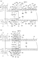
- the pipe joint A has a grooved flange 1 formed at the connection end of the joint body 10 as shown in FIGS. 1 to 3, and another joint body 10 'to be connected.
- This is a fluid coupling which is joined with a grooved flange 1 ′ with a gasket 2 such as an O-ring sandwiched therebetween, and is fastened and fixed by a ferrule clamp 3.
- This type of pipe joint A is referred to as, for example, a ferrule joint, a ferrule joint, a sanitary joint, or the like, and is a fluid joint used to connect an elastically deformable flexible pipe B as a pipe body.
- the pipe joint A is provided with a joint body 10 having a nipple 11 provided along the insertion space S of the flexible tube B, and opposed to the nipple 11 in the radial direction.
- the main ferrule 20 includes a holding member 30 provided inside the ferrule 20, and a clamp 40 provided to tighten the joint body 10 and the ferrule 20 by approaching the same in the axial direction. I have.
- the insertion space S of the flexible tube B is formed between the nipple 11 of the joint body 10, the ferrule 20 and the holding member 30.
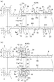
- 1A and 1B show a first pipe joint A1 as a specific example of the pipe joint A.
- FIGS. 2A and 2B show a second pipe joint A2
- FIGS. 3A and 3B show a third pipe joint A3.
- the flexible tube B is formed of a soft synthetic resin such as vinyl chloride or a flexible soft material such as silicone rubber or other rubber, and can be cut to a predetermined length by a cutting tool (not shown) such as scissors.
- a cutting tool such as scissors.
- a hose or a tube is used.
- the flexible tube B preferably has a flat inner surface B1 and an outer surface B2, and a cut surface B3 of which is cut at a substantially vertical or nearly vertical angle. 1 (a), 2 (a) and 3 (a), a connection end Ba of a predetermined length is inserted from a cut surface B3 of the flexible tube B into the insertion space S. It is.
- a hose having a single-layer structure is used, and the connection end Ba is slightly expanded and deformed from the other portions to the nipple 11 of the joint body 10 described later. Are fitted along.
- a hose or a tube having a multi-layer structure is used, or the connection end Ba of the flexible tube B is fitted to the nipple 11 without deforming the connection end Ba from other portions. Such changes can be made.
- the joint body 10 is formed in a substantially cylindrical shape from a rigid material such as a metal such as brass or stainless steel or a hard synthetic resin, and has a grooved flange 1 at one axial end thereof.
- the other end of the joint body 10 in the axial direction has a nipple 11 and a first flange 12.
- the nipple 11 is formed in a cylindrical shape having an outer diameter substantially equal to the inner diameter of the flexible tube B (connection end portion Ba) or slightly smaller than the inner diameter of the flexible tube B (connection end portion Ba).
- a flexible tube B has an inner surface B1 on its nipple 11 side. Are inserted so as to face each other along the outer peripheral surface 11a.
- the nipple 11 and the flexible pipe are used.
- the first flange 12 is formed so as to protrude axially in a double cylindrical shape with the insertion space S of B interposed therebetween.
- an annular recess is formed in an inner peripheral edge of the first flange 12 on the first facing surface 12 a facing the pressing member 30 described later in the axial direction.
- a groove 12b is formed.
- a first chamfered portion 12c is formed on an inner peripheral edge of a first facing surface 12a of the first flange 12 that faces an after-mentioned pressing member 30 in the axial direction. Is formed.
- a third fitting A3 shown in FIGS. 3A and 3B as another example of the fitting body 10 the first fitting without inserting the insertion space S of the flexible pipe B at the base end of the nipple 11.
- the first facing surface 12a of the flange 12 is formed smoothly.
- the first flange 12 can be changed to a shape other than the illustrated example.
- the ferrule 20 is formed of a rigid material such as a metal such as brass or stainless steel or a hard synthetic resin, and is formed in a substantially cylindrical shape having an inner diameter slightly larger than the outer diameter of the flexible tube B (connection end Ba).
- a second flange 21 is provided at one end in the axial direction, and a pressing surface 22 is provided at the inner periphery.
- the second flange 21 is formed to protrude annularly in the radial direction so as to be joined to the first flange 12 of the joint body 10 in the axial direction.
- the ferrule 20 is disposed outside the flexible tube B by inserting the flexible tube B into its inner space. Is done.
- the pressing member 30 and the ferrule 20 are moved in the axial direction toward the joint body 10 so that the first flange 12 and the second flange 21 are moved closer to each other. 20 are arranged.
- the pressing surface 22 tightens the first flange 12 and the second flange 21 in the axial direction by a clamp 40 described later.
- a pressing member 30 described later is pressed toward the outer surface B2 of the inserted flexible tube B.
- the pressing surface 22 is preferably formed as a tapered surface that is gradually reduced in diameter as it is separated from the second flange 21 in the axial direction.
- the ferrule 20 preferably has a convex portion 23 on an outer surface separated from the second flange 21 in the axial direction.
- a second chamfered portion 21b is formed between an inner peripheral edge of the second opposing surface 21a which faces the pressing member 30 described later in the axial direction and an end edge of the tapered pressing surface 22.
- an annular concave and convex inner surface is formed on one end of the tapered pressing surface 22 having a large diameter. 22a.
- Each of the first fitting A1, the second fitting A2, and the third fitting A3 has the convex portion 23 formed in a flange shape.
- the pressing surface 22 and the convex portion 23 can be changed to shapes other than the illustrated example.
- the holding member 30 is made of a soft material such as rubber or soft synthetic resin, or a hard material such as metal or hard synthetic resin, and has an inner diameter that is substantially the same as the outer diameter of the flexible tube B (connection end Ba). It is formed in an annular shape that can be elastically deformed at least in the radial direction.
- the pressing member 30 is made of a hard material, for example, by forming a slit or a slit in a part in the circumferential direction and separating the holding member 30 like a C-shaped ring, elastic deformation in the radial direction becomes possible. Further, as shown in FIGS.
- the holding member 30 is provided outside the flexible tube B by inserting the flexible tube B into the inner hole 30a. Be placed. After the insertion of the flexible tube B into the insertion space S, the pressing member 30 and the ferrule 20 are moved in the axial direction toward the joint main body 10 to thereby move the outer surface B2 of the flexible tube B and the pressing surface 22 of the ferrule 20. Are arranged so as to sandwich the holding member 30 in the radial direction. As shown in FIGS. 1B, 2B, and 3B, the holding member 30 is ferruled in a state where the first flange 12 and the second flange 21 are clamped by a clamp 40 described later.
- a reduced diameter portion 31 formed so as to enter a part of the outer surface B2 of the flexible tube B by the pressing surface 22 of 20 and a part of the inner surface B1 of the flexible tube B is pressed against the outer peripheral surface 11a of the nipple 11. have.
- the pressing member 30 makes the outer surface B2 of the flexible tube B inserted into the pressing surface 22 of the ferrule 20 after being inserted. Pressed toward, it is elastically reduced in diameter.
- a portion of the outer surface B2 of the flexible tube B is compressed and deformed in the radial direction by the reduced diameter portion 31 serving as the inner peripheral surface of the pressing member 30, and the reduced diameter portion 31 is moved outside the flexible tube B. It digs into a part of the surface B2. Thereby, a part of the outer surface B2 radially opposed to the part of the outer surface B2 radially compressed and deformed in the flexible tube B is brought into pressure contact with the outer peripheral surface 11a of the nipple 11 to be in close contact therewith.
- FIGS. 1A and 1B show specific examples of the holding member 30, the entire holding member 30 is formed of a soft material such as rubber, and the reduced diameter portion 31 serving as the inner peripheral surface is formed outside the flexible tube B. It is formed on a smooth surface substantially parallel to the surface B2. Further, in the case of the first pipe joint A1 shown in FIGS. 1A and 1B, a first inclined surface 32 that is opposed to the pressing surface 22 of the ferrule 20 substantially parallel to the one end side outer surface of the pressing member 30 is provided. Has formed. On the other end side of the holding member 30, an annular projection 33 is formed to fit in an axial direction with an annular concave groove 12 b formed on the inner peripheral edge of the first facing surface 12 a of the first flange 12.
- the outer surface on the other end side of the holding member 30 is provided.
- a second inclined surface 34 is formed substantially in parallel with the first chamfered portion 12c formed on the inner peripheral edge of the first opposed surface 12a of the first flange 12 in the axial direction.
- the outer surface 35 is formed on the outer peripheral surface of the holding member 30.
- a flange 36 is formed which is sandwiched between the first facing surface 12 a of the first flange 12 and the second facing surface 21 a of the second flange 21.
- an uneven portion may be formed on the first inclined surface 32 in order to reduce the frictional resistance with the pressing surface 22 of the ferrule 20.
- a plurality of grooves can be formed in the inner or outer peripheral surface of the holding member 30 in the axial direction. Accordingly, it is possible to prevent the trouble that the fluid that has entered from the nipple 11 intrudes between the layers of the hose or tube having a multilayer structure.
- the clamp 40 is a tool having a conventionally well-known structure used for a ferrule joint or the like for fastening an annular body 42 having a circumferentially continuous annular groove 41 formed inside thereof with a fastener (not shown).
- a ferrule clamp for example, it is called a ferrule clamp, a clamp band, a sanitary clamp, or the like.
- the annular body 42 be divided into a plurality in the circumferential direction, and that the fastener be manually operable such as a wing nut.
- the clamp 40 may be the same type as the ferrule clamp 3 for fastening the grooved flanges 1 to each other, or may be the same as the ferrule clamp 3 if the sizes match.
- the clamp 40 As a specific example of the clamp 40, various types of structures such as a split (two-split) structure and a three-split (three-split) structure described in JP-A-2006-226345 can be used. As shown in FIGS. 1 (b), 2 (b) and 3 (b), after the flexible tube B is inserted into the insertion space S, the clamp 40 12 and the clamp 40 are set over the second flange 21 of the ferrule 20 so that the annular groove 41 is fitted to the outer peripheral ends of the first flange 12 and the second flange 21. The flange 12 and the second flange 21 are moved close to each other in the axial direction, and are fastened and fixed.
- the outer peripheral end radially facing the annular groove 41 of the clamp 40 preferably has a first tapered portion 12t.
- the first tapered portion 12t is formed by, for example, chamfering a surface of the first flange 12 opposite to the first facing surface 12a.
- the outer peripheral end radially opposed to the annular groove 41 of the clamp 40 preferably has a second tapered portion 21t.
- the second tapered portion 21t is formed by chamfering a surface of the second flange 21 opposite to the second facing surface 21a.
- the joint body 10 By pressing the first flange 12 and the second flange 21 of the ferrule 20 close to each other in the axial direction with the clamp 40 and tightening, the pressing member 30 is elastically reduced in diameter by the pressing surface 22 of the ferrule 20, The reduced diameter portion 31 is pushed into a part of the outer surface B2 of the flexible tube B.
- the flexible tube B can be brought into close contact with the nipple 11 of the joint main body 10 and can be detachably connected to the nipple 11 of the joint body 10 only by tightening with the clamp 40.
- the flexible tube B can be easily installed on site without special tools such as a caulking machine, compared to the conventional one that requires integration with the nipple of the joint body by reducing the diameter of the pipe and caulking pipe by the caulking machine. Can be replaced.
- the replacement work of the flexible tube B can be performed by a person who does not have any specialized knowledge and is convenient.
- the flexible tube B needs to be replaced every time the fluid passing through the flexible tube B is changed for reasons such as flavor, taste, discoloration, etc. B can be easily replaced. For this reason, not only is the workability excellent, but also the management is excellent, as compared with the conventional one which requires preparing a plurality of types of spare tubes which are reduced in diameter and connected to the ferrule joint by a caulking machine.
- the pressing surface 22 of the ferrule 20 radially opposed to the outer surface (first inclined surface 32) of the holding member 30 is tapered so that its diameter is gradually reduced as it is separated from the second flange 21 in the axial direction. It is preferably a surface.
- the outer surface (first inclined surface 32) of the holding member 30 is fastened by moving the second flange 21 of the ferrule 20 close to the first flange 12 of the joint body 10 in the axial direction with the clamp 40 and tightening.
- the tapered surface serving as the pressing surface 22 slides smoothly along.
- the outer surface (first inclined surface 32) of the holding member 30 is gradually reduced in diameter by the tapered surface serving as the pressing surface 22, so that the reduced diameter portion 31 is formed on a part of the outer surface B2 of the flexible tube B. It is pushed in gradually. Therefore, the approach movement of the first flange 12 and the second flange 21 by the clamp 40 can be performed smoothly, and a part of the inner surface B1 of the flexible tube B can be securely adhered to the outer peripheral surface 11a of the nipple 11.
- the holding member 30 is made of an elastic material such as rubber, which has a high frictional resistance and is inferior in sliding properties with the pressing surface 22 of the ferrule 20, the first flange 12 and the second flange 12 are clamped by the clamp 40.
- the two flanges 21 can be surely moved closer to each other, so that the workability is more excellent.
- first flange 12 of the joint main body 10 and the second flange 21 of the ferrule 20 are provided with a first tapered portion 12 t (of the first flange 12) at an outer peripheral end radially opposed to the annular groove 41 of the clamp 40.
- it has a second taper 21t (of the second flange 21).
- the first flange 12 and the second flange 21 are slightly separated in the axial direction.
- the first tapered portion 12t of the first flange 12 and the second tapered portion 21t of the second flange 21 fit into the annular groove 41 of the clamp 40, respectively.
- the first flange 12 and the second flange 21 can be moved closer by the tightening operation of the clamp 40. Therefore, the clamping operation of the clamp 40 can be performed without being affected by the gap between the first flange 12 and the second flange 21.
- the pressing member 30 is made of an elastic material such as rubber which has a high frictional resistance and is inferior in slidability with the pressing surface 22 of the ferrule 20, the first flange 12 and the second flange 21 are separated. Even in this case, the first flange 12 and the second flange 21 can be surely moved closer to each other by the clamp 40, and the workability is further improved.
- the ferrule 20 has a convex portion 23 on an outer surface separated from the second flange 21 in the axial direction.
- a clamp 40 or a finger is hooked on the convex portion 23 of the ferrule 20 and pulled in a direction in which the first flange 12 and the second flange 21 are separated from each other.
- the pressing surface 22 of 20 is separated from the pressing member 30 and can be moved away. Therefore, the pipe joint A can be quickly disassembled.
- the pressing member 30 has a large frictional resistance, such as rubber, and is in close contact with the pressing surface 22 of the ferrule 20, the pressing member 30 can be disassembled in a short time, and the workability is further improved.
- the pressing member 30 made of a soft material has been described in the illustrated example, but the present invention is not limited to this.
- the holding member 30 may be used.
Landscapes
- Engineering & Computer Science (AREA)
- General Engineering & Computer Science (AREA)
- Mechanical Engineering (AREA)
- Flanged Joints, Insulating Joints, And Other Joints (AREA)
- Joints That Cut Off Fluids, And Hose Joints (AREA)
Abstract
La présente invention amène un tuyau souple en contact étroit avec un mamelon d'un corps de joint par simple serrage par l'intermédiaire d'une pince de façon à ce que le tuyau souple soit relié amovible au mamelon. Ce joint de tuyau est caractérisé en ce qu'il comprend : un corps de joint qui comporte un mamelon disposé le long d'un espace d'insertion d'un tuyau souple élastiquement déformable ; une première bride qui est formée de manière à faire saillie radialement vers l'extérieur à partir du mamelon et radialement vers la section d'extrémité de direction axiale du corps de joint ; une virole cylindrique qui est disposée de façon à être en regard du mamelon avec l'espace d'insertion du tuyau souple pris en sandwich entre ceux-ci dans la direction radiale ; une seconde bride qui est formée de manière à faire saillie radialement de façon à être en regard axialement de la première bride au niveau de la section d'extrémité de direction axiale de la virole ; un élément de pression annulaire qui est élastiquement déformable dans la direction radiale et qui est disposé entre la virole et la surface externe du tuyau souple inséré dans l'espace d'insertion ; et une pince qui est disposée à travers la première bride et la seconde bride de façon à approcher la première bride et la seconde bride et à les serrer dans la direction dans laquelle la première bride et la seconde bride sont en regard, la virole ayant une surface de pression qui est formée, lorsque la première bride et la seconde bride sont serrées par la pince, de façon à pousser l'élément de pression contre la surface externe du tuyau souple inséré dans l'espace d'insertion, et l'élément de pression ayant une section de diamètre réduit qui est formée de telle sorte que la surface de pression amène l'élément de pression à entrer dans la surface externe du tuyau souple et que la surface interne du tuyau souple est en contact de pression avec la surface périphérique externe du mamelon.
Applications Claiming Priority (2)
| Application Number | Priority Date | Filing Date | Title |
|---|---|---|---|
| JP2018128695A JP6770753B2 (ja) | 2018-07-06 | 2018-07-06 | 管継手 |
| JP2018-128695 | 2018-07-06 |
Publications (1)
| Publication Number | Publication Date |
|---|---|
| WO2020009180A1 true WO2020009180A1 (fr) | 2020-01-09 |
Family
ID=69059531
Family Applications (1)
| Application Number | Title | Priority Date | Filing Date |
|---|---|---|---|
| PCT/JP2019/026599 Ceased WO2020009180A1 (fr) | 2018-07-06 | 2019-07-04 | Joint de tuyau |
Country Status (2)
| Country | Link |
|---|---|
| JP (1) | JP6770753B2 (fr) |
| WO (1) | WO2020009180A1 (fr) |
Citations (7)
| Publication number | Priority date | Publication date | Assignee | Title |
|---|---|---|---|---|
| JPS58180789A (ja) * | 1982-04-19 | 1983-10-22 | Kyokuto Kaihatsu Kogyo Co Ltd | 絞り出し式ポンプのポンピングチユ−ブ固定装置 |
| JPS5993589A (ja) * | 1982-11-17 | 1984-05-30 | 倉地 久治 | ホ−ス類の接続装置 |
| US4634153A (en) * | 1985-09-03 | 1987-01-06 | Hydrafit, Inc. | Reusable hose fitting |
| JP2008208898A (ja) * | 2007-02-26 | 2008-09-11 | Nippon Flex Kk | ホース接続のフランジ式コネクタ |
| JP2010506115A (ja) * | 2006-10-07 | 2010-02-25 | エイフレックス ホース リミテッド | ホース接続具 |
| JP2012042004A (ja) * | 2010-08-20 | 2012-03-01 | Seiko Corp | ホース継手構造並びにホース継手 |
| JP2017502226A (ja) * | 2013-12-16 | 2017-01-19 | ワトソン−マーロウ ブレーデル ビー.ヴイ. | 腔に収容されるチューブのための端部嵌合構造及びチューブを腔内に設置する方法 |
Family Cites Families (6)
| Publication number | Priority date | Publication date | Assignee | Title |
|---|---|---|---|---|
| DE2634348A1 (de) * | 1976-07-30 | 1978-02-02 | Nippon Oil Seal Ind Co Ltd | Schlauchkupplung |
| US4564222A (en) * | 1984-08-27 | 1986-01-14 | Hydrasearch Co., Inc. | Separable coupling for thin-walled flexible hose |
| GB2227803B (en) * | 1989-01-10 | 1993-03-24 | Titeflex Corp | End fitting for hoses |
| KR980008820U (ko) * | 1996-07-10 | 1998-04-30 | 박강훈 | 합성수지 호오스 연결구 |
| JP2007285343A (ja) * | 2006-04-13 | 2007-11-01 | Ihara Science Corp | 継手構造 |
| US20070241555A1 (en) * | 2006-04-13 | 2007-10-18 | Elmer Scott Welch | Field replaceable sanitary hose end coupling |
-
2018
- 2018-07-06 JP JP2018128695A patent/JP6770753B2/ja active Active
-
2019
- 2019-07-04 WO PCT/JP2019/026599 patent/WO2020009180A1/fr not_active Ceased
Patent Citations (7)
| Publication number | Priority date | Publication date | Assignee | Title |
|---|---|---|---|---|
| JPS58180789A (ja) * | 1982-04-19 | 1983-10-22 | Kyokuto Kaihatsu Kogyo Co Ltd | 絞り出し式ポンプのポンピングチユ−ブ固定装置 |
| JPS5993589A (ja) * | 1982-11-17 | 1984-05-30 | 倉地 久治 | ホ−ス類の接続装置 |
| US4634153A (en) * | 1985-09-03 | 1987-01-06 | Hydrafit, Inc. | Reusable hose fitting |
| JP2010506115A (ja) * | 2006-10-07 | 2010-02-25 | エイフレックス ホース リミテッド | ホース接続具 |
| JP2008208898A (ja) * | 2007-02-26 | 2008-09-11 | Nippon Flex Kk | ホース接続のフランジ式コネクタ |
| JP2012042004A (ja) * | 2010-08-20 | 2012-03-01 | Seiko Corp | ホース継手構造並びにホース継手 |
| JP2017502226A (ja) * | 2013-12-16 | 2017-01-19 | ワトソン−マーロウ ブレーデル ビー.ヴイ. | 腔に収容されるチューブのための端部嵌合構造及びチューブを腔内に設置する方法 |
Also Published As
| Publication number | Publication date |
|---|---|
| JP6770753B2 (ja) | 2020-10-21 |
| JP2020008060A (ja) | 2020-01-16 |
Similar Documents
| Publication | Publication Date | Title |
|---|---|---|
| EP3022478B1 (fr) | Raccords à nervures de rigidité arquées | |
| TWI657213B (zh) | 開口環聯結器 | |
| US4593942A (en) | Coupling for thin-walled flexible hose | |
| CN103930704B (zh) | 用于柔性管的连接装置 | |
| EP2894381B1 (fr) | Raccord de tuyau | |
| US10054249B2 (en) | Universal tube fitting adaptable for different sized tubes | |
| JP6798713B2 (ja) | 管継手 | |
| JP5134341B2 (ja) | フランジ式管継手及び鋼管の膨出部形成装置 | |
| WO2011027766A1 (fr) | Joint de tuyau | |
| US20180231166A1 (en) | Tube fitting | |
| JP2020133640A5 (fr) | ||
| CA2871341A1 (fr) | Joint d'etancheite coulissant composite pour joints haute pression | |
| US11519531B2 (en) | Ferrule for a conduit fitting | |
| CA2682038A1 (fr) | Piece de fixation etanche pour tube en acier inoxydable | |
| JP5953586B2 (ja) | 管継手 | |
| JP2015203439A5 (fr) | ||
| US6000729A (en) | Hose coupling | |
| WO2020009180A1 (fr) | Joint de tuyau | |
| JP2011069484A (ja) | ホース継手 | |
| US20040061333A1 (en) | Conduit coupling | |
| US20070013189A1 (en) | Sealing fitting for stainless steel tubing | |
| TWI910260B (zh) | 管接頭、壓環及管的接合方法 | |
| JP2020008060A5 (fr) | ||
| JP2007016942A (ja) | ホース継手 | |
| CN107002924A (zh) | 管接头及淋浴软管连接结构 |
Legal Events
| Date | Code | Title | Description |
|---|---|---|---|
| 121 | Ep: the epo has been informed by wipo that ep was designated in this application |
Ref document number: 19830128 Country of ref document: EP Kind code of ref document: A1 |
|
| NENP | Non-entry into the national phase |
Ref country code: DE |
|
| 122 | Ep: pct application non-entry in european phase |
Ref document number: 19830128 Country of ref document: EP Kind code of ref document: A1 |