WO2020009180A1 - 管継手 - Google Patents
管継手 Download PDFInfo
- Publication number
- WO2020009180A1 WO2020009180A1 PCT/JP2019/026599 JP2019026599W WO2020009180A1 WO 2020009180 A1 WO2020009180 A1 WO 2020009180A1 JP 2019026599 W JP2019026599 W JP 2019026599W WO 2020009180 A1 WO2020009180 A1 WO 2020009180A1
- Authority
- WO
- WIPO (PCT)
- Prior art keywords
- flange
- ferrule
- nipple
- flexible tube
- clamp
- Prior art date
- Legal status (The legal status is an assumption and is not a legal conclusion. Google has not performed a legal analysis and makes no representation as to the accuracy of the status listed.)
- Ceased
Links
Images

Classifications
-
- F—MECHANICAL ENGINEERING; LIGHTING; HEATING; WEAPONS; BLASTING
- F16—ENGINEERING ELEMENTS AND UNITS; GENERAL MEASURES FOR PRODUCING AND MAINTAINING EFFECTIVE FUNCTIONING OF MACHINES OR INSTALLATIONS; THERMAL INSULATION IN GENERAL
- F16L—PIPES; JOINTS OR FITTINGS FOR PIPES; SUPPORTS FOR PIPES, CABLES OR PROTECTIVE TUBING; MEANS FOR THERMAL INSULATION IN GENERAL
- F16L23/00—Flanged joints
- F16L23/16—Flanged joints characterised by the sealing means
- F16L23/18—Flanged joints characterised by the sealing means the sealing means being rings
- F16L23/22—Flanged joints characterised by the sealing means the sealing means being rings made exclusively of a material other than metal
-
- F—MECHANICAL ENGINEERING; LIGHTING; HEATING; WEAPONS; BLASTING
- F16—ENGINEERING ELEMENTS AND UNITS; GENERAL MEASURES FOR PRODUCING AND MAINTAINING EFFECTIVE FUNCTIONING OF MACHINES OR INSTALLATIONS; THERMAL INSULATION IN GENERAL
- F16L—PIPES; JOINTS OR FITTINGS FOR PIPES; SUPPORTS FOR PIPES, CABLES OR PROTECTIVE TUBING; MEANS FOR THERMAL INSULATION IN GENERAL
- F16L33/00—Arrangements for connecting hoses to rigid members; Rigid hose-connectors, i.e. single members engaging both hoses
- F16L33/22—Arrangements for connecting hoses to rigid members; Rigid hose-connectors, i.e. single members engaging both hoses with means not mentioned in the preceding groups for gripping the hose between inner and outer parts
Definitions
- the present invention relates to a pipe joint used to connect an elastically deformable flexible pipe such as a hose or a tube to a production line pursuing sanitary properties such as food, beverage, medicine, cosmetics, dairy farming, and chemistry. More specifically, the present invention relates to a pipe joint called a ferrule joint, a ferrule joint, a sanitary joint, or the like, in which flanges formed at connection ends of the joint are fastened and fixed by a clamp.
- a tubular joint body has a nipple and a connection portion, a nipple is inserted into a connection end of a pipe such as a hose or a tube, and a sleeve (caulking pipe) ) Is deformed by a caulking machine to reduce the diameter of the connection end of the pipe, thereby connecting the pipe so that it cannot be displaced in the axial direction (for example, see Patent Document 1).
- connection portion of the joint body is a grooved flange formed at the connection end of the joint body as a ferrule joint or the like, and is joined by sandwiching a gasket (packing) such as an O-ring between the flanges and tightening with a clamp.
- a gasket such as an O-ring between the flanges and tightening with a clamp.
- a ferrule joint or the like generally has a structure in which pipes that cannot be deformed among pipes are connected to each other, and cannot be easily installed when the production line is complicatedly bent, and thus is not suitable.
- a pipe joint to which an elastically deformable flexible pipe such as a hose or a tube can be connected as a pipe body as in Patent Document 1.
- Patent Literature 1 since it is necessary to reduce the diameter of the pipe and the swaged pipe by a caulking machine and integrate the pipe and the nipple of the joint body, at the installation site of the production line, every time the fluid passing through the pipe is changed. It was difficult to easily replace tubes such as hoses and tubes. For this reason, in order to easily perform tube replacement work, it is necessary to prepare a spare tube whose diameter is connected to the ferrule joint by a caulking machine, and a large number of tubes are connected. On the site, there is a problem that a large number of spare pipes are required and their management becomes troublesome.
- a pipe joint has a joint body having a nipple provided along an insertion space of an elastically deformable flexible tube, and a radially outer side of the nipple and the joint body.
- a first flange formed to protrude radially at an axial end of the joint body, and a cylindrical ferrule provided so as to radially oppose the insertion space of the nipple and the flexible tube with the insertion space interposed therebetween.
- a second flange formed at an axial end of the ferrule in a radial direction so as to face the first flange in the axial direction, and an outer surface of the flexible tube inserted into the insertion space.
- the ferrule is configured to press the holding member toward the outer surface of the flexible tube inserted into the insertion space in a state where the first flange and the second flange are tightened by the clamp.
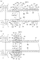
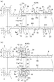
- the pipe joint A has a grooved flange 1 formed at the connection end of the joint body 10 as shown in FIGS. 1 to 3, and another joint body 10 'to be connected.
- This is a fluid coupling which is joined with a grooved flange 1 ′ with a gasket 2 such as an O-ring sandwiched therebetween, and is fastened and fixed by a ferrule clamp 3.
- This type of pipe joint A is referred to as, for example, a ferrule joint, a ferrule joint, a sanitary joint, or the like, and is a fluid joint used to connect an elastically deformable flexible pipe B as a pipe body.
- the pipe joint A is provided with a joint body 10 having a nipple 11 provided along the insertion space S of the flexible tube B, and opposed to the nipple 11 in the radial direction.
- the main ferrule 20 includes a holding member 30 provided inside the ferrule 20, and a clamp 40 provided to tighten the joint body 10 and the ferrule 20 by approaching the same in the axial direction. I have.
- the insertion space S of the flexible tube B is formed between the nipple 11 of the joint body 10, the ferrule 20 and the holding member 30.
- 1A and 1B show a first pipe joint A1 as a specific example of the pipe joint A.
- FIGS. 2A and 2B show a second pipe joint A2
- FIGS. 3A and 3B show a third pipe joint A3.
- the flexible tube B is formed of a soft synthetic resin such as vinyl chloride or a flexible soft material such as silicone rubber or other rubber, and can be cut to a predetermined length by a cutting tool (not shown) such as scissors.
- a cutting tool such as scissors.
- a hose or a tube is used.
- the flexible tube B preferably has a flat inner surface B1 and an outer surface B2, and a cut surface B3 of which is cut at a substantially vertical or nearly vertical angle. 1 (a), 2 (a) and 3 (a), a connection end Ba of a predetermined length is inserted from a cut surface B3 of the flexible tube B into the insertion space S. It is.
- a hose having a single-layer structure is used, and the connection end Ba is slightly expanded and deformed from the other portions to the nipple 11 of the joint body 10 described later. Are fitted along.
- a hose or a tube having a multi-layer structure is used, or the connection end Ba of the flexible tube B is fitted to the nipple 11 without deforming the connection end Ba from other portions. Such changes can be made.
- the joint body 10 is formed in a substantially cylindrical shape from a rigid material such as a metal such as brass or stainless steel or a hard synthetic resin, and has a grooved flange 1 at one axial end thereof.
- the other end of the joint body 10 in the axial direction has a nipple 11 and a first flange 12.
- the nipple 11 is formed in a cylindrical shape having an outer diameter substantially equal to the inner diameter of the flexible tube B (connection end portion Ba) or slightly smaller than the inner diameter of the flexible tube B (connection end portion Ba).
- a flexible tube B has an inner surface B1 on its nipple 11 side. Are inserted so as to face each other along the outer peripheral surface 11a.
- the nipple 11 and the flexible pipe are used.
- the first flange 12 is formed so as to protrude axially in a double cylindrical shape with the insertion space S of B interposed therebetween.
- an annular recess is formed in an inner peripheral edge of the first flange 12 on the first facing surface 12 a facing the pressing member 30 described later in the axial direction.
- a groove 12b is formed.
- a first chamfered portion 12c is formed on an inner peripheral edge of a first facing surface 12a of the first flange 12 that faces an after-mentioned pressing member 30 in the axial direction. Is formed.
- a third fitting A3 shown in FIGS. 3A and 3B as another example of the fitting body 10 the first fitting without inserting the insertion space S of the flexible pipe B at the base end of the nipple 11.
- the first facing surface 12a of the flange 12 is formed smoothly.
- the first flange 12 can be changed to a shape other than the illustrated example.
- the ferrule 20 is formed of a rigid material such as a metal such as brass or stainless steel or a hard synthetic resin, and is formed in a substantially cylindrical shape having an inner diameter slightly larger than the outer diameter of the flexible tube B (connection end Ba).
- a second flange 21 is provided at one end in the axial direction, and a pressing surface 22 is provided at the inner periphery.
- the second flange 21 is formed to protrude annularly in the radial direction so as to be joined to the first flange 12 of the joint body 10 in the axial direction.
- the ferrule 20 is disposed outside the flexible tube B by inserting the flexible tube B into its inner space. Is done.
- the pressing member 30 and the ferrule 20 are moved in the axial direction toward the joint body 10 so that the first flange 12 and the second flange 21 are moved closer to each other. 20 are arranged.
- the pressing surface 22 tightens the first flange 12 and the second flange 21 in the axial direction by a clamp 40 described later.
- a pressing member 30 described later is pressed toward the outer surface B2 of the inserted flexible tube B.
- the pressing surface 22 is preferably formed as a tapered surface that is gradually reduced in diameter as it is separated from the second flange 21 in the axial direction.
- the ferrule 20 preferably has a convex portion 23 on an outer surface separated from the second flange 21 in the axial direction.
- a second chamfered portion 21b is formed between an inner peripheral edge of the second opposing surface 21a which faces the pressing member 30 described later in the axial direction and an end edge of the tapered pressing surface 22.
- an annular concave and convex inner surface is formed on one end of the tapered pressing surface 22 having a large diameter. 22a.
- Each of the first fitting A1, the second fitting A2, and the third fitting A3 has the convex portion 23 formed in a flange shape.
- the pressing surface 22 and the convex portion 23 can be changed to shapes other than the illustrated example.
- the holding member 30 is made of a soft material such as rubber or soft synthetic resin, or a hard material such as metal or hard synthetic resin, and has an inner diameter that is substantially the same as the outer diameter of the flexible tube B (connection end Ba). It is formed in an annular shape that can be elastically deformed at least in the radial direction.
- the pressing member 30 is made of a hard material, for example, by forming a slit or a slit in a part in the circumferential direction and separating the holding member 30 like a C-shaped ring, elastic deformation in the radial direction becomes possible. Further, as shown in FIGS.
- the holding member 30 is provided outside the flexible tube B by inserting the flexible tube B into the inner hole 30a. Be placed. After the insertion of the flexible tube B into the insertion space S, the pressing member 30 and the ferrule 20 are moved in the axial direction toward the joint main body 10 to thereby move the outer surface B2 of the flexible tube B and the pressing surface 22 of the ferrule 20. Are arranged so as to sandwich the holding member 30 in the radial direction. As shown in FIGS. 1B, 2B, and 3B, the holding member 30 is ferruled in a state where the first flange 12 and the second flange 21 are clamped by a clamp 40 described later.
- a reduced diameter portion 31 formed so as to enter a part of the outer surface B2 of the flexible tube B by the pressing surface 22 of 20 and a part of the inner surface B1 of the flexible tube B is pressed against the outer peripheral surface 11a of the nipple 11. have.
- the pressing member 30 makes the outer surface B2 of the flexible tube B inserted into the pressing surface 22 of the ferrule 20 after being inserted. Pressed toward, it is elastically reduced in diameter.
- a portion of the outer surface B2 of the flexible tube B is compressed and deformed in the radial direction by the reduced diameter portion 31 serving as the inner peripheral surface of the pressing member 30, and the reduced diameter portion 31 is moved outside the flexible tube B. It digs into a part of the surface B2. Thereby, a part of the outer surface B2 radially opposed to the part of the outer surface B2 radially compressed and deformed in the flexible tube B is brought into pressure contact with the outer peripheral surface 11a of the nipple 11 to be in close contact therewith.
- FIGS. 1A and 1B show specific examples of the holding member 30, the entire holding member 30 is formed of a soft material such as rubber, and the reduced diameter portion 31 serving as the inner peripheral surface is formed outside the flexible tube B. It is formed on a smooth surface substantially parallel to the surface B2. Further, in the case of the first pipe joint A1 shown in FIGS. 1A and 1B, a first inclined surface 32 that is opposed to the pressing surface 22 of the ferrule 20 substantially parallel to the one end side outer surface of the pressing member 30 is provided. Has formed. On the other end side of the holding member 30, an annular projection 33 is formed to fit in an axial direction with an annular concave groove 12 b formed on the inner peripheral edge of the first facing surface 12 a of the first flange 12.
- the outer surface on the other end side of the holding member 30 is provided.
- a second inclined surface 34 is formed substantially in parallel with the first chamfered portion 12c formed on the inner peripheral edge of the first opposed surface 12a of the first flange 12 in the axial direction.
- the outer surface 35 is formed on the outer peripheral surface of the holding member 30.
- a flange 36 is formed which is sandwiched between the first facing surface 12 a of the first flange 12 and the second facing surface 21 a of the second flange 21.
- an uneven portion may be formed on the first inclined surface 32 in order to reduce the frictional resistance with the pressing surface 22 of the ferrule 20.
- a plurality of grooves can be formed in the inner or outer peripheral surface of the holding member 30 in the axial direction. Accordingly, it is possible to prevent the trouble that the fluid that has entered from the nipple 11 intrudes between the layers of the hose or tube having a multilayer structure.
- the clamp 40 is a tool having a conventionally well-known structure used for a ferrule joint or the like for fastening an annular body 42 having a circumferentially continuous annular groove 41 formed inside thereof with a fastener (not shown).
- a ferrule clamp for example, it is called a ferrule clamp, a clamp band, a sanitary clamp, or the like.
- the annular body 42 be divided into a plurality in the circumferential direction, and that the fastener be manually operable such as a wing nut.
- the clamp 40 may be the same type as the ferrule clamp 3 for fastening the grooved flanges 1 to each other, or may be the same as the ferrule clamp 3 if the sizes match.
- the clamp 40 As a specific example of the clamp 40, various types of structures such as a split (two-split) structure and a three-split (three-split) structure described in JP-A-2006-226345 can be used. As shown in FIGS. 1 (b), 2 (b) and 3 (b), after the flexible tube B is inserted into the insertion space S, the clamp 40 12 and the clamp 40 are set over the second flange 21 of the ferrule 20 so that the annular groove 41 is fitted to the outer peripheral ends of the first flange 12 and the second flange 21. The flange 12 and the second flange 21 are moved close to each other in the axial direction, and are fastened and fixed.
- the outer peripheral end radially facing the annular groove 41 of the clamp 40 preferably has a first tapered portion 12t.
- the first tapered portion 12t is formed by, for example, chamfering a surface of the first flange 12 opposite to the first facing surface 12a.
- the outer peripheral end radially opposed to the annular groove 41 of the clamp 40 preferably has a second tapered portion 21t.
- the second tapered portion 21t is formed by chamfering a surface of the second flange 21 opposite to the second facing surface 21a.
- the joint body 10 By pressing the first flange 12 and the second flange 21 of the ferrule 20 close to each other in the axial direction with the clamp 40 and tightening, the pressing member 30 is elastically reduced in diameter by the pressing surface 22 of the ferrule 20, The reduced diameter portion 31 is pushed into a part of the outer surface B2 of the flexible tube B.
- the flexible tube B can be brought into close contact with the nipple 11 of the joint main body 10 and can be detachably connected to the nipple 11 of the joint body 10 only by tightening with the clamp 40.
- the flexible tube B can be easily installed on site without special tools such as a caulking machine, compared to the conventional one that requires integration with the nipple of the joint body by reducing the diameter of the pipe and caulking pipe by the caulking machine. Can be replaced.
- the replacement work of the flexible tube B can be performed by a person who does not have any specialized knowledge and is convenient.
- the flexible tube B needs to be replaced every time the fluid passing through the flexible tube B is changed for reasons such as flavor, taste, discoloration, etc. B can be easily replaced. For this reason, not only is the workability excellent, but also the management is excellent, as compared with the conventional one which requires preparing a plurality of types of spare tubes which are reduced in diameter and connected to the ferrule joint by a caulking machine.
- the pressing surface 22 of the ferrule 20 radially opposed to the outer surface (first inclined surface 32) of the holding member 30 is tapered so that its diameter is gradually reduced as it is separated from the second flange 21 in the axial direction. It is preferably a surface.
- the outer surface (first inclined surface 32) of the holding member 30 is fastened by moving the second flange 21 of the ferrule 20 close to the first flange 12 of the joint body 10 in the axial direction with the clamp 40 and tightening.
- the tapered surface serving as the pressing surface 22 slides smoothly along.
- the outer surface (first inclined surface 32) of the holding member 30 is gradually reduced in diameter by the tapered surface serving as the pressing surface 22, so that the reduced diameter portion 31 is formed on a part of the outer surface B2 of the flexible tube B. It is pushed in gradually. Therefore, the approach movement of the first flange 12 and the second flange 21 by the clamp 40 can be performed smoothly, and a part of the inner surface B1 of the flexible tube B can be securely adhered to the outer peripheral surface 11a of the nipple 11.
- the holding member 30 is made of an elastic material such as rubber, which has a high frictional resistance and is inferior in sliding properties with the pressing surface 22 of the ferrule 20, the first flange 12 and the second flange 12 are clamped by the clamp 40.
- the two flanges 21 can be surely moved closer to each other, so that the workability is more excellent.
- first flange 12 of the joint main body 10 and the second flange 21 of the ferrule 20 are provided with a first tapered portion 12 t (of the first flange 12) at an outer peripheral end radially opposed to the annular groove 41 of the clamp 40.
- it has a second taper 21t (of the second flange 21).
- the first flange 12 and the second flange 21 are slightly separated in the axial direction.
- the first tapered portion 12t of the first flange 12 and the second tapered portion 21t of the second flange 21 fit into the annular groove 41 of the clamp 40, respectively.
- the first flange 12 and the second flange 21 can be moved closer by the tightening operation of the clamp 40. Therefore, the clamping operation of the clamp 40 can be performed without being affected by the gap between the first flange 12 and the second flange 21.
- the pressing member 30 is made of an elastic material such as rubber which has a high frictional resistance and is inferior in slidability with the pressing surface 22 of the ferrule 20, the first flange 12 and the second flange 21 are separated. Even in this case, the first flange 12 and the second flange 21 can be surely moved closer to each other by the clamp 40, and the workability is further improved.
- the ferrule 20 has a convex portion 23 on an outer surface separated from the second flange 21 in the axial direction.
- a clamp 40 or a finger is hooked on the convex portion 23 of the ferrule 20 and pulled in a direction in which the first flange 12 and the second flange 21 are separated from each other.
- the pressing surface 22 of 20 is separated from the pressing member 30 and can be moved away. Therefore, the pipe joint A can be quickly disassembled.
- the pressing member 30 has a large frictional resistance, such as rubber, and is in close contact with the pressing surface 22 of the ferrule 20, the pressing member 30 can be disassembled in a short time, and the workability is further improved.
- the pressing member 30 made of a soft material has been described in the illustrated example, but the present invention is not limited to this.
- the holding member 30 may be used.
Landscapes
- Engineering & Computer Science (AREA)
- General Engineering & Computer Science (AREA)
- Mechanical Engineering (AREA)
- Flanged Joints, Insulating Joints, And Other Joints (AREA)
- Joints That Cut Off Fluids, And Hose Joints (AREA)
Abstract
クランプによる締め付けのみで継手本体のニップルに対し可撓管を密着させて着脱可能に連結する。 弾性変形可能な可撓管の挿入空間に沿って設けられたニップルを有する継手本体と、ニップルよりも径方向外側で且つ継手本体の軸方向端部に径方向へ突出して形成される第一フランジと、ニップルと可撓管の挿入空間を挟んで径方向へ対向するように設けられる筒状のへルールと、へルールの軸方向端部に第一フランジと軸方向へ対向するように径方向へ突出して形成される第二フランジと、挿入空間に差し込まれた可撓管の外表面とへルールとの間に設けられる径方向へ弾性変形可能な環状の押さえ部材と、第一フランジ及び第二フランジに亘って両者の対向方向へ接近させ締め付けるように設けられるクランプと、を備え、へルールは、クランプによる第一フランジと第二フランジの締め付け状態で、挿入空間に差し込まれた可撓管の外表面に向け押さえ部材を押し込むように形成される押圧面を有し、押さえ部材は、押圧面により可撓管の外表面に入り込んで可撓管の内表面がニップルの外周面に圧接するように形成される縮径部を有することを特徴とする管継手。
Description
本発明は、例えば食品、飲料、医薬、化粧品、酪農、化学などのサニタリー性を追求した製造ラインに、ホースやチューブなどの弾性変形可能な可撓管を接続するために用いられる管継手に関する。
詳しくは、継手の接続端に形成されるフランジ同士をクランプで締め付けて固定するへルール継手,フェルール継手,サニタリー継手などと呼ばれる管継手に関する。
詳しくは、継手の接続端に形成されるフランジ同士をクランプで締め付けて固定するへルール継手,フェルール継手,サニタリー継手などと呼ばれる管継手に関する。
従来、この種の管継手として、筒状の継手本体がニップルと接続部を有し、ホースやチューブなどの管体の接続端部に対してニップルが挿入され、その外側に設けられるスリーブ(カシメパイプ)をカシメ機で縮径変形させることにより、管体の接続端部が抜け止めされて軸方向へ位置ズレ不能に接続するものがある(例えば、特許文献1参照)。
継手本体の接続部は、へルール継手などとして継手本体の接続端に形成される溝付のフランジであり、フランジ同士の間にOリングなどのガスケット(パッキン)を挟んで接合され、クランプにより締め付けて固定される。
クランプで締め付けるへルール継手などは、レンチやスパナなどの工具不要で且つ手締めにて簡単に連結及び分解が可能となるため、製造ラインを頻繁に分解洗浄する必要がある食品、飲料、医薬、化粧品、酪農、化学などの業界で広く使われている。
継手本体の接続部は、へルール継手などとして継手本体の接続端に形成される溝付のフランジであり、フランジ同士の間にOリングなどのガスケット(パッキン)を挟んで接合され、クランプにより締め付けて固定される。
クランプで締め付けるへルール継手などは、レンチやスパナなどの工具不要で且つ手締めにて簡単に連結及び分解が可能となるため、製造ラインを頻繁に分解洗浄する必要がある食品、飲料、医薬、化粧品、酪農、化学などの業界で広く使われている。
ところで、食品や飲料などの製造ラインでは、管体を通る流体が変更される度に、流体からの着香、味覚、変色などの理由で管体を交換する必要があった。
またへルール継手などは、管体の中でも変形不能なパイプ同士を連結する構造が一般的であり、製造ラインが複雑に曲がる場合には簡単に設置できず不向きであった。
これに対し、特許文献1のように管体としてホースやチューブなどの弾性変形可能な可撓管が連結可能な管継手もある。
しかし、特許文献1では、カシメ機により管体及びカシメパイプを縮径変形させて継手本体のニップルと一体化する必要があるため、製造ラインの設置現場では管体を通る流体が変更される度に、ホースやチューブなどの管体を簡単に交換することが困難であった。
このため、管体の交換作業を簡単に行うには、へルール継手に対してカシメ機で縮径接続した予備の管体を用意しておく必要があり、多数の管体を接続している現場では、予備の管体も多数必要になって、それらの管理が面倒になるという問題があった。
このような課題を解決するために本発明に係る管継手は、弾性変形可能な可撓管の挿入空間に沿って設けられたニップルを有する継手本体と、前記ニップルよりも径方向外側で且つ前記継手本体の軸方向端部に径方向へ突出して形成される第一フランジと、前記ニップルと前記可撓管の前記挿入空間を挟んで径方向へ対向するように設けられる筒状のへルールと、前記へルールの軸方向端部に前記第一フランジと軸方向へ対向するように径方向へ突出して形成される第二フランジと、前記挿入空間に差し込まれた前記可撓管の外表面と前記へルールとの間に設けられる径方向へ弾性変形可能な環状の押さえ部材と、前記第一フランジ及び前記第二フランジに亘って両者の対向方向へ接近させ締め付けるように設けられるクランプと、を備え、前記へルールは、前記クランプによる前記第一フランジと前記第二フランジの締め付け状態で、前記挿入空間に差し込まれた前記可撓管の前記外表面に向け前記押さえ部材を押し込むように形成される押圧面を有し、前記押さえ部材は、前記押圧面により前記可撓管の前記外表面に入り込んで前記可撓管の内表面が前記ニップルの外周面に圧接するように形成される縮径部を有することを特徴とする。
以下、本発明の実施形態を図面に基づいて詳細に説明する。
本発明の実施形態に係る管継手Aは、図1~図3に示すように、継手本体10の接続端に形成される溝付のフランジ1を有し、接続される他の継手本体10′の溝付フランジ1′との間にOリングなどのガスケット2を挟んで接合され、へルールクランプ3により締め付けて固定する流体継手である。この種の管継手Aは、例えばへルール継手,フェルール継手,サニタリー継手などと呼ばれ、その中でも管体として弾性変形可能な可撓管Bを連結するために用いられる流体継手である。
詳しく説明すると、本発明の実施形態に係る管継手Aは、可撓管Bの挿入空間Sに沿って設けられたニップル11を有する継手本体10と、ニップル11と径方向へ対向するように設けられるへルール20と、へルール20の内側に設けられる押さえ部材30と、継手本体10及びへルール20を軸方向へ接近させて締め付けるように設けられるクランプ40と、を主要な構成要素として備えている。
可撓管Bの挿入空間Sは、継手本体10のニップル11とへルール20及び押さえ部材30との間に形成される。
管継手Aの具体例として図1(a)(b)に第一管継手A1を示す。管継手Aの変形例として、図2(a)(b)に第二管継手A2を示し、図3(a)(b)に第三管継手A3を示している。
可撓管Bは、例えば塩化ビニルなどの軟質合成樹脂やシリコーンゴムやその他のゴムなどの可撓性を有する軟質材料で成形され、ハサミなどの刃物(図示しない)により所定長さに切断可能な例えばホースやチューブなどである。
可撓管Bとしては、平坦な内表面B1及び外表面B2を有し、その切断面B3が略垂直又は垂直に近い角度で切断されたものを用いることが好ましい。
挿入空間Sに対しては、図1(a),図2(a)及び図3(a)に示されるように、可撓管Bの切断面B3から所定長さの接続端部Baが差し込まれる。
可撓管Bの具体例として図示される例では、単層構造のホースが用いられ、接続端部Baをその他の部位より若干拡径変形させた状態で、後述する継手本体10のニップル11に沿って嵌合している。
また、その他の例として図示しないが、複数層構造のホースやチューブなどを用いることや、可撓管Bの接続端部Baをその他の部位より拡径変形させずにニップル11と嵌合することなどの変更が可能である。
継手本体10は、例えば真鍮やステンレスなどの金属や硬質合成樹脂などの剛性材料で略円筒状に形成され、その軸方向一端側に溝付のフランジ1を有している。
継手本体10の軸方向他端側は、ニップル11と第一フランジ12を有している。
ニップル11は、可撓管B(接続端部Ba)の内径と略同じか又は可撓管B(接続端部Ba)の内径よりも若干小さな外径を有する円筒状に形成され、挿入空間Sに差し込まれた可撓管Bの内表面B1と径方向へ対向する外周面11aを有する。ニップル11の外周面11aには、軸方向へ抜け止め用の凹凸部11bを形成することが好ましい。
第一フランジ12は、ニップル11の外周面11aよりも径方向外側において継手本体10の軸方向他端部に径方向へ環状に突出して形成される。
さらにニップル11の外側に形成される挿入空間Sには、図1(a),図2(a)及び図3(a)に示されるように、可撓管Bがその内表面B1をニップル11の外周面11aに沿って対向させるように差し込まれる。
継手本体10の一例として図1(a)(b)に示される第一管継手A1及び図2(a)(b)に示される第二管継手A2の場合には、ニップル11と可撓管Bの挿入空間Sを挟んで第一フランジ12が軸方向へ二重筒状に突出するように形成されている。
さらに図1(a)(b)に示される第一管継手A1の例では、第一フランジ12の第一対向面12aにおいて後述する押さえ部材30と軸方向へ対向する内周縁に円環状の凹溝12bを形成している。
図2(a)(b)に示される第二管継手A2の例では、第一フランジ12の第一対向面12aにおいて後述する押さえ部材30と軸方向へ対向する内周縁に第一面取り部12cを形成している。
また継手本体10の他の例として図3(a)(b)に示される第三管継手A3の場合には、ニップル11の基端に可撓管Bの挿入空間Sを挟むことなく第一フランジ12の第一対向面12aが平滑に形成されている。
なお、それ以外の継手本体10の変形例として図示しないが、第一フランジ12を図示例以外の形状に変更することも可能である。
へルール20は、例えば真鍮やステンレスなどの金属や硬質合成樹脂などの剛性材料で、可撓管B(接続端部Ba)の外径よりも若干大きな内径を有する略円筒状に形成され、その軸方向一端部に第二フランジ21を有し、内周に押圧面22を有している。
第二フランジ21は、継手本体10の第一フランジ12と軸方向へ対向して接合するように径方向へ環状に突出して形成される。
さらにへルール20は、図1(a),図2(a)及び図3(a)に示されるように、その内側空間に可撓管Bを挿通することで可撓管Bの外側に配置される。挿入空間Sに対する可撓管Bの差し込み後には、押さえ部材30とへルール20を継手本体10に向けて軸方向へ動かすことにより、第一フランジ12と第二フランジ21を接近させるようにへルール20が配置される。
押圧面22は、図1(b),図2(b)及び図3(b)に示されるように、後述するクランプ40により第一フランジ12と第二フランジ21を軸方向へ接近させて締め付けた状態で、差し込み後の可撓管Bの外表面B2に向けて後述する押さえ部材30を押し込むように構成される。
押圧面22は、第二フランジ21から軸方向へ離隔することに伴って徐々に縮径されるテーパー面に形成することが好ましい。
さらにへルール20は、第二フランジ21と軸方向へ離隔した外面に凸部23を有することが好ましい。
へルール20の一例として図1(a)(b)に示される第一管継手A1及び図2(a)(b)に示される第二管継手A2の場合には、第二フランジ21の第二対向面21aにおいて後述する押さえ部材30と軸方向へ対向する内周縁と、テーパー状に形成された押圧面22の端縁との間に第二面取り部21bを形成している。
またへルール20の他の例として図3(a)(b)に示される第三管継手A3の場合には、テーパー状に形成された押圧面22の大径な一端側に環状の凹凸内面22aを形成している。
第一管継手A1,第二管継手A2及び第三管継手A3は、凸部23をフランジ状に形成している。
なお、それ以外のへルール20の変形例として図示しないが、押圧面22や凸部23を図示例以外の形状に変更することも可能である。
またへルール20の他の例として図3(a)(b)に示される第三管継手A3の場合には、テーパー状に形成された押圧面22の大径な一端側に環状の凹凸内面22aを形成している。
第一管継手A1,第二管継手A2及び第三管継手A3は、凸部23をフランジ状に形成している。
なお、それ以外のへルール20の変形例として図示しないが、押圧面22や凸部23を図示例以外の形状に変更することも可能である。
押さえ部材30は、例えばゴムや軟質合成樹脂などの軟質材料か又は金属や硬質合成樹脂などの硬質材料で、可撓管B(接続端部Ba)の外径と略同じ内径を有し、且つ少なくとも径方向へ弾性変形可能な環状に形成される。
押さえ部材30が硬質材料製である場合には、例えばC形リングのように周方向の一部にスリットやすり割りなどを形成して分離することにより、径方向への弾性変形が可能になる。
さらに押さえ部材30は、図1(a),図2(a)及び図3(a)に示されるように、その内側孔30aに可撓管Bを挿通することで可撓管Bの外側に配置される。挿入空間Sに対する可撓管Bの差し込み後は、押さえ部材30とへルール20を継手本体10に向けて軸方向へ動かすことにより、可撓管Bの外表面B2とへルール20の押圧面22との間に押さえ部材30を径方向へ挟むように配置される。
また押さえ部材30は、図1(b),図2(b)及び図3(b)に示されるように、後述するクランプ40による第一フランジ12と第二フランジ21の締め付け状態で、へルール20の押圧面22により可撓管Bの外表面B2の一部に入り込んで可撓管Bの内表面B1の一部がニップル11の外周面11aに圧接するように形成される縮径部31を有している。
つまり、後述するクランプ40で第一フランジ12と第二フランジ21が軸方向へ接近して締め付けられると、押さえ部材30はへルール20の押圧面22で差し込み後の可撓管Bの外表面B2向け押圧されて弾性的に縮径変形する。これに伴い、押さえ部材30の内周面となる縮径部31によって、可撓管Bの外表面B2の一部は径方向へ圧縮変形して、縮径部31が可撓管Bの外表面B2の一部に食い込む。これにより、可撓管Bにおいて径方向へ圧縮変形した外表面B2の一部と径方向へ対向する内表面B1の一部は、ニップル11の外周面11aに圧接されて密着する。
押さえ部材30の具体例として図1~図3に示される場合には、押さえ部材30の全体がゴムなどの軟質材料で形成され、内周面となる縮径部31を可撓管Bの外表面B2と略平行な平滑面に形成している。
さらに図1(a)(b)に示される第一管継手A1の場合には、押さえ部材30の一端側外面に、へルール20の押圧面22と略平行に対向する第一傾斜面32を形成している。押さえ部材30の他端側には、第一フランジ12の第一対向面12aの内周縁に形成された円環状の凹溝12bと軸方向へ嵌め合う円環状の突起33を形成している。
図2(a)(b)に示される第二管継手A2の場合には、押さえ部材30の一端側外面に形成した第一傾斜面32に加えて、押さえ部材30の他端側外面には、第一フランジ12の第一対向面12aの内周縁に形成された第一面取り部12cと軸方向へ略平行に対向する第二傾斜面34を形成している。
また図3(a)(b)に示される第三管継手A3の場合には、テーパー状の押圧面22の大径な一端側に形成された環状の凹凸内面22aと径方向に対向する凹凸外面35を押さえ部材30の外周面に形成している。押さえ部材30の軸方向一端部には、第一フランジ12の第一対向面12aと第二フランジ21の第二対向面21aとの間に挟まれる鍔部36を形成している。
なお、それ以外の押さえ部材30の変形例として図示しないが、へルール20の押圧面22との摩擦抵抗を減らすため第一傾斜面32に凹凸部位を形成することや、例えばO形リングなどが複数個並べて配置されることで押さえ部材30を構成するなど、図示例以外の形状に変更することも可能である。
特に可撓管Bとして複数層構造のホースやチューブを用いる場合には、押さえ部材30の内周面や外周面に複数の溝を軸方向へ形成することも可能である。これにより、ニップル11から浸入した流体が、複数層構造のホースやチューブの層間に侵入するトラブルを防止することができる。
クランプ40とは、周方向へ連続する環状溝41が内側に形成された環状体42を締め具(図示しない)で締め付け固定するためのへルール継手などに用いられる従来周知構造の工具であり、例えばへルールクランプ,クランプバンド,サニタリークランプ,などと呼ばれる。
クランプ40の中でも、環状体42が周方向へ複数に分割され、締め具として蝶ナットなどの手動操作可能なものが好ましい。クランプ40は、溝付のフランジ1同士を締め付けるへルールクランプ3と同種のものや、サイズが合えばへルールクランプ3と同じものであってもよい。
クランプ40の具体例としては、特開2006-226345号公報に記載される二ツ割(二分割)構造や、三ツ割(三分割)構造など、種々の構造のものが使用可能である。
クランプ40は、図1(b),図2(b)及び図3(b)に示されるように、挿入空間Sに対して可撓管Bが差し込まれた後に、継手本体10の第一フランジ12とへルール20の第二フランジ21に亘ってクランプ40を、環状溝41が第一フランジ12及び第二フランジ21の外周端と嵌合するようにセットし、締め具の回転操作によって第一フランジ12及び第二フランジ21が軸方向へ接近移動され、締め付け固定される。
これに加えて、継手本体10の第一フランジ12において、クランプ40の環状溝41と径方向へ対向する外周端は、第一先細部12tを有することが好ましい。第一先細部12tは、第一フランジ12の第一対向面12aと反対側の面を面取り加工することなどで形成される。
へルール20の第二フランジ21において、クランプ40の環状溝41と径方向へ対向する外周端は、第二先細部21tを有することが好ましい。第二先細部21tは、第二フランジ21の第二対向面21aと反対側の面を面取り加工することなどで形成される。
第一先細部12t及び第二先細部21tによって、第一フランジ12及び第二フランジ21の外周端幅は、クランプ40の環状溝41の開口幅よりも肉薄に形成される。
へルール20の第二フランジ21において、クランプ40の環状溝41と径方向へ対向する外周端は、第二先細部21tを有することが好ましい。第二先細部21tは、第二フランジ21の第二対向面21aと反対側の面を面取り加工することなどで形成される。
第一先細部12t及び第二先細部21tによって、第一フランジ12及び第二フランジ21の外周端幅は、クランプ40の環状溝41の開口幅よりも肉薄に形成される。
このような本発明の実施形態に係る管継手A(第一管継手A1,第二管継手A2及び第三管継手A3)によると、挿入空間Sに対する可撓管Bの差し込み後に、継手本体10の第一フランジ12とへルール20の第二フランジ21をクランプ40で軸方向へ接近移動させて締め付けることにより、へルール20の押圧面22で押さえ部材30が弾性的に縮径変形して、縮径部31を可撓管Bの外表面B2の一部に押し込む。
これに伴い、押さえ部材30の縮径部31で可撓管Bの外表面B2の一部が径方向へ圧縮変形して、可撓管Bの内表面B1の一部をニップル11の外周面11aに圧接させる。
したがって、クランプ40による締め付けのみで継手本体10のニップル11に対し可撓管Bを密着させて着脱可能に連結することができる。
その結果、カシメ機による管体及びカシメパイプの縮径変形で継手本体のニップルと一体化させる必要がある従来のものに比べ、カシメ機などの専用工具が無くても現場で可撓管Bを簡単に交換できる。しかも可撓管Bの交換作業は、専門知識が無い者でもできて便利である。
さらに、可撓管Bを通る流体が変更される度に着香、味覚、変色などの理由で可撓管Bの交換が必要であっても、製造ラインの設置現場において流体毎に可撓管Bを簡単に交換できる。このため、へルール継手に対してカシメ機で縮径接続した予備の管体を複数種類用意する必要がある従来のものに比べ、作業性に優れるばかりでなく、管理上も優れる。
特に、押さえ部材30の外面(第一傾斜面32)と径方向に対向するへルール20の押圧面22は、第二フランジ21から軸方向へ離隔することに伴って徐々に縮径されるテーパー面であることが好ましい。
この場合には、クランプ40で継手本体10の第一フランジ12に対しへルール20の第二フランジ21を軸方向へ接近移動させて締め付けることにより、押さえ部材30の外面(第一傾斜面32)に沿って押圧面22となるテーパー面がスムーズに摺動する。
このため、押圧面22となるテーパー面で押さえ部材30の外面(第一傾斜面32)を徐々に縮径変形させて、縮径部31が可撓管Bの外表面B2の一部に対し徐々に押し込まれる。
したがって、クランプ40による第一フランジ12と第二フランジ21の接近移動をスムーズに行って、ニップル11の外周面11aに可撓管Bの内表面B1の一部を確実に密着させることができる。
その結果、押さえ部材30がゴムなどのような摩擦抵抗が大きくてへルール20の押圧面22との摺動性に劣る弾性材料からなる場合であっても、クランプ40により第一フランジ12と第二フランジ21を確実に接近移動できて、より作業性に優れる。
さらに、継手本体10の第一フランジ12とへルール20の第二フランジ21は、クランプ40の環状溝41と径方向へ対向する外周端に(第一フランジ12の)第一先細部12tと(第二フランジ21の)第二先細部21tを有することが好ましい。
この場合には、継手本体10の第一フランジ12とへルール20の第二フランジ21に亘ってクランプ40をセットすることにより、第一フランジ12と第二フランジ21が軸方向へ若干離れていても、第一フランジ12の第一先細部12tと、第二フランジ21の第二先細部21tがそれぞれクランプ40の環状溝41内に嵌入する。
このため、第一フランジ12と第二フランジ21が軸方向へ若干離れた状態でも、クランプ40の締め付け動作により第一フランジ12と第二フランジ21が接近移動可能になる。
したがって、第一フランジ12と第二フランジ21の隙間に影響されずにクランプ40の締め付け動作を行うことができる。
その結果、押さえ部材30がゴムなどのような摩擦抵抗が大きくてへルール20の押圧面22との摺動性に劣る弾性材料からなるため、第一フランジ12と第二フランジ21が離れている場合であっても、クランプ40により第一フランジ12と第二フランジ21を確実に接近移動できて、より作業性に優れる。
また、へルール20は、第二フランジ21と軸方向へ離隔した外面に凸部23有することが好ましい。
この場合には、管継手Aの分解時においてへルール20の凸部23に対し、クランプ40や指などを引っ掛けて第一フランジ12と第二フランジ21が離隔する方向へ引っ張ることにより、へルール20の押圧面22が押さえ部材30から剥がれて離隔移動可能になる。
したがって、管継手Aを素早く分解することができる。
その結果、押さえ部材30がゴムなどのような摩擦抵抗が大きくてへルール20の押圧面22に密着する場合であっても、短時間に分解できて、より作業性に優れる。
この場合には、管継手Aの分解時においてへルール20の凸部23に対し、クランプ40や指などを引っ掛けて第一フランジ12と第二フランジ21が離隔する方向へ引っ張ることにより、へルール20の押圧面22が押さえ部材30から剥がれて離隔移動可能になる。
したがって、管継手Aを素早く分解することができる。
その結果、押さえ部材30がゴムなどのような摩擦抵抗が大きくてへルール20の押圧面22に密着する場合であっても、短時間に分解できて、より作業性に優れる。
なお、前示の実施形態において図示例では、軟質材料製の押さえ部材30のみを説明したが、これに限定されず、軟質材料製の押さえ部材30に代えてC形リングなどの硬質材料製の押さえ部材30を用いてもよい。
A 管継手 10 継手本体
11 ニップル 11a 外周面
12 第一フランジ 12t 第一先細部
20 へルール 21 第二フランジ
21t 第二先細部 22 押圧面
23 凸部 30 押さえ部材
31 縮径部 32 外面(第一傾斜面)
40 クランプ 41 環状溝
B 可撓管 B1 内表面
B2 外表面 S 挿入空間
11 ニップル 11a 外周面
12 第一フランジ 12t 第一先細部
20 へルール 21 第二フランジ
21t 第二先細部 22 押圧面
23 凸部 30 押さえ部材
31 縮径部 32 外面(第一傾斜面)
40 クランプ 41 環状溝
B 可撓管 B1 内表面
B2 外表面 S 挿入空間
Claims (4)
- 弾性変形可能な可撓管の挿入空間に沿って設けられたニップルを有する継手本体と、
前記ニップルよりも径方向外側で且つ前記継手本体の軸方向端部に径方向へ突出して形成される第一フランジと、
前記ニップルと前記可撓管の前記挿入空間を挟んで径方向へ対向するように設けられる筒状のへルールと、
前記へルールの軸方向端部に前記第一フランジと軸方向へ対向するように径方向へ突出して形成される第二フランジと、
前記挿入空間に差し込まれた前記可撓管の外表面と前記へルールとの間に設けられる径方向へ弾性変形可能な環状の押さえ部材と、
前記第一フランジ及び前記第二フランジに亘って両者の対向方向へ接近させ締め付けるように設けられるクランプと、を備え、
前記へルールは、前記クランプによる前記第一フランジと前記第二フランジの締め付け状態で、前記挿入空間に差し込まれた前記可撓管の前記外表面に向け前記押さえ部材を押し込むように形成される押圧面を有し、
前記押さえ部材は、前記押圧面により前記可撓管の前記外表面に入り込んで前記可撓管の内表面が前記ニップルの外周面に圧接するように形成される縮径部を有することを特徴とする管継手。 - 前記押さえ部材の外面と径方向に対向する前記へルールの前記押圧面が、前記第二フランジから軸方向へ離隔することに伴って徐々に縮径されるテーパー面であることを特徴とする請求項1記載の管継手。
- 前記継手本体の前記第一フランジと前記へルールの前記第二フランジが、前記クランプの環状溝と径方向へ対向する外周端に第一先細部と第二先細部を有することを特徴とする請求項1又は2記載の管継手。
- 前記へルールが、前記第二フランジと軸方向へ離隔した外面に凸部を有することを特徴とする請求項1又は2記載の管継手。
Applications Claiming Priority (2)
| Application Number | Priority Date | Filing Date | Title |
|---|---|---|---|
| JP2018-128695 | 2018-07-06 | ||
| JP2018128695A JP6770753B2 (ja) | 2018-07-06 | 2018-07-06 | 管継手 |
Publications (1)
| Publication Number | Publication Date |
|---|---|
| WO2020009180A1 true WO2020009180A1 (ja) | 2020-01-09 |
Family
ID=69059531
Family Applications (1)
| Application Number | Title | Priority Date | Filing Date |
|---|---|---|---|
| PCT/JP2019/026599 Ceased WO2020009180A1 (ja) | 2018-07-06 | 2019-07-04 | 管継手 |
Country Status (2)
| Country | Link |
|---|---|
| JP (1) | JP6770753B2 (ja) |
| WO (1) | WO2020009180A1 (ja) |
Citations (7)
| Publication number | Priority date | Publication date | Assignee | Title |
|---|---|---|---|---|
| JPS58180789A (ja) * | 1982-04-19 | 1983-10-22 | Kyokuto Kaihatsu Kogyo Co Ltd | 絞り出し式ポンプのポンピングチユ−ブ固定装置 |
| JPS5993589A (ja) * | 1982-11-17 | 1984-05-30 | 倉地 久治 | ホ−ス類の接続装置 |
| US4634153A (en) * | 1985-09-03 | 1987-01-06 | Hydrafit, Inc. | Reusable hose fitting |
| JP2008208898A (ja) * | 2007-02-26 | 2008-09-11 | Nippon Flex Kk | ホース接続のフランジ式コネクタ |
| JP2010506115A (ja) * | 2006-10-07 | 2010-02-25 | エイフレックス ホース リミテッド | ホース接続具 |
| JP2012042004A (ja) * | 2010-08-20 | 2012-03-01 | Seiko Corp | ホース継手構造並びにホース継手 |
| JP2017502226A (ja) * | 2013-12-16 | 2017-01-19 | ワトソン−マーロウ ブレーデル ビー.ヴイ. | 腔に収容されるチューブのための端部嵌合構造及びチューブを腔内に設置する方法 |
Family Cites Families (6)
| Publication number | Priority date | Publication date | Assignee | Title |
|---|---|---|---|---|
| DE2634348A1 (de) * | 1976-07-30 | 1978-02-02 | Nippon Oil Seal Ind Co Ltd | Schlauchkupplung |
| US4564222A (en) * | 1984-08-27 | 1986-01-14 | Hydrasearch Co., Inc. | Separable coupling for thin-walled flexible hose |
| GB2227803B (en) * | 1989-01-10 | 1993-03-24 | Titeflex Corp | End fitting for hoses |
| KR980008820U (ko) * | 1996-07-10 | 1998-04-30 | 박강훈 | 합성수지 호오스 연결구 |
| JP2007285343A (ja) * | 2006-04-13 | 2007-11-01 | Ihara Science Corp | 継手構造 |
| US20070241555A1 (en) * | 2006-04-13 | 2007-10-18 | Elmer Scott Welch | Field replaceable sanitary hose end coupling |
-
2018
- 2018-07-06 JP JP2018128695A patent/JP6770753B2/ja active Active
-
2019
- 2019-07-04 WO PCT/JP2019/026599 patent/WO2020009180A1/ja not_active Ceased
Patent Citations (7)
| Publication number | Priority date | Publication date | Assignee | Title |
|---|---|---|---|---|
| JPS58180789A (ja) * | 1982-04-19 | 1983-10-22 | Kyokuto Kaihatsu Kogyo Co Ltd | 絞り出し式ポンプのポンピングチユ−ブ固定装置 |
| JPS5993589A (ja) * | 1982-11-17 | 1984-05-30 | 倉地 久治 | ホ−ス類の接続装置 |
| US4634153A (en) * | 1985-09-03 | 1987-01-06 | Hydrafit, Inc. | Reusable hose fitting |
| JP2010506115A (ja) * | 2006-10-07 | 2010-02-25 | エイフレックス ホース リミテッド | ホース接続具 |
| JP2008208898A (ja) * | 2007-02-26 | 2008-09-11 | Nippon Flex Kk | ホース接続のフランジ式コネクタ |
| JP2012042004A (ja) * | 2010-08-20 | 2012-03-01 | Seiko Corp | ホース継手構造並びにホース継手 |
| JP2017502226A (ja) * | 2013-12-16 | 2017-01-19 | ワトソン−マーロウ ブレーデル ビー.ヴイ. | 腔に収容されるチューブのための端部嵌合構造及びチューブを腔内に設置する方法 |
Also Published As
| Publication number | Publication date |
|---|---|
| JP2020008060A (ja) | 2020-01-16 |
| JP6770753B2 (ja) | 2020-10-21 |
Similar Documents
| Publication | Publication Date | Title |
|---|---|---|
| EP3434955B1 (en) | Fittings having arcuate stiffness ribs | |
| TWI657213B (zh) | 開口環聯結器 | |
| JP4088923B2 (ja) | 波形のたわみ管用の管継手 | |
| US4593942A (en) | Coupling for thin-walled flexible hose | |
| CN103930704B (zh) | 用于柔性管的连接装置 | |
| EP2894381B1 (en) | Tube fitting | |
| US10054249B2 (en) | Universal tube fitting adaptable for different sized tubes | |
| JP6798713B2 (ja) | 管継手 | |
| JP5134341B2 (ja) | フランジ式管継手及び鋼管の膨出部形成装置 | |
| WO2011027766A1 (ja) | ホース継手 | |
| JP2020133640A5 (ja) | ||
| CA2871341A1 (en) | A composite sliding gasket for high-pressure joints | |
| US11519531B2 (en) | Ferrule for a conduit fitting | |
| CA2682038A1 (en) | Sealing fitting for stainless steel tubing | |
| JP5953586B2 (ja) | 管継手 | |
| JP2015203439A5 (ja) | ||
| US6000729A (en) | Hose coupling | |
| WO2020009180A1 (ja) | 管継手 | |
| JP2011069484A (ja) | ホース継手 | |
| US20040061333A1 (en) | Conduit coupling | |
| US20070013189A1 (en) | Sealing fitting for stainless steel tubing | |
| TWI910260B (zh) | 管接頭、壓環及管的接合方法 | |
| JP2020008060A5 (ja) | ||
| JP2007016942A (ja) | ホース継手 | |
| CN107002924A (zh) | 管接头及淋浴软管连接结构 |
Legal Events
| Date | Code | Title | Description |
|---|---|---|---|
| 121 | Ep: the epo has been informed by wipo that ep was designated in this application |
Ref document number: 19830128 Country of ref document: EP Kind code of ref document: A1 |
|
| NENP | Non-entry into the national phase |
Ref country code: DE |
|
| 122 | Ep: pct application non-entry in european phase |
Ref document number: 19830128 Country of ref document: EP Kind code of ref document: A1 |