WO2020009233A1 - Bouchon - Google Patents
Bouchon Download PDFInfo
- Publication number
- WO2020009233A1 WO2020009233A1 PCT/JP2019/026853 JP2019026853W WO2020009233A1 WO 2020009233 A1 WO2020009233 A1 WO 2020009233A1 JP 2019026853 W JP2019026853 W JP 2019026853W WO 2020009233 A1 WO2020009233 A1 WO 2020009233A1
- Authority
- WO
- WIPO (PCT)
- Prior art keywords
- suction
- plug
- container
- cap
- straw
- Prior art date
- Legal status (The legal status is an assumption and is not a legal conclusion. Google has not performed a legal analysis and makes no representation as to the accuracy of the status listed.)
- Ceased
Links
Images





Classifications
-
- B—PERFORMING OPERATIONS; TRANSPORTING
- B65—CONVEYING; PACKING; STORING; HANDLING THIN OR FILAMENTARY MATERIAL
- B65D—CONTAINERS FOR STORAGE OR TRANSPORT OF ARTICLES OR MATERIALS, e.g. BAGS, BARRELS, BOTTLES, BOXES, CANS, CARTONS, CRATES, DRUMS, JARS, TANKS, HOPPERS, FORWARDING CONTAINERS; ACCESSORIES, CLOSURES, OR FITTINGS THEREFOR; PACKAGING ELEMENTS; PACKAGES
- B65D75/00—Packages comprising articles or materials partially or wholly enclosed in strips, sheets, blanks, tubes or webs of flexible sheet material, e.g. in folded wrappers
- B65D75/52—Details
- B65D75/58—Opening or contents-removing devices added or incorporated during package manufacture
Definitions
- the present invention relates to a spout for sucking and attaching to a container for storing liquid or powder, which can be re-opened and re-closed with a relatively simple structure, has high sealing properties, and has a high sealing property.
- the present invention relates to a spout that requires less residual liquid.
- a container for storing liquid or powder a container called a pouch with a plug, in which a plug is attached to a flexible bag-like container, is known.
- a pouch with a spout does not use the entire contents at once, but even when used for dispensing, the container shrinks according to the amount used, so the contents do not touch the air to the end It has the advantage that it can be used.
- Patent Literature 2 The plug structure and nozzle described in Patent Literature 2 are plugs used for the pouch with the plug, and have dimensions of an inner peripheral surface of a plug and a head of a male member in a conventional plug (Patent Literature 1).
- the accuracy requirement was very high, and it could not be adopted for inexpensive items such as disposable containers. It was intended to solve the problem of difficulty in responding.
- Conventional pouches with a spout generally have a method in which a bag is attached to a predetermined server and the contents are naturally dropped out of a spout attached to a lower part of the bag.
- the plug described in Patent Document 2 has a similar structure.
- the problem to be solved by the present invention is to propose a plug capable of discharging the contents by suction from the upper part of the container and which can be resealed.
- a synthetic resin plug used by being attached to an opening of a container, comprising a plug main body, a suction straw, and a cap.
- a cylindrical outer cylinder provided with a male screw to which the cap is screwed, a flange portion for holding the entire plug, and a welded portion for welding to the opening of the container, are integrally formed
- the suction straw has a cylindrical tube portion fitted to the inner periphery of the outer cylinder of the plug body, and a collar portion for locking to the outer cylinder, and the cap is provided on the outer cylinder of the plug body.
- a movable valve slidable in the axial direction on the inner circumference of the inner cylinder is provided inside the cylinder, and the movable valve has a suction plug.
- the container has flexibility
- the suction straw has a tapered vertical body having a cross-sectional shape in which a gap is formed between the container and the container when the contents of the container are suctioned from one end of the tube portion by the suction plug.
- the pipe portion may be provided with an air hole capable of sucking air in the container.
- the collar of the suction straw and the cap may be sealed by a contact ring provided inside the top of the cap.
- the collar of the suction straw and the cap may be sealed by an elastic packing inserted inside the top of the cap.
- Another aspect of the present invention is a suction content discharging container provided with the above-mentioned plug.
- the spout according to the present invention has a relatively simple structure composed of a small number of components, such as a spout main body, a suction straw and a cap, but can be used for suction which was impossible with a conventional spout. Opening and resealing became possible by the action of the movable valve.
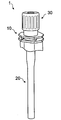
- FIG. 1 is a perspective view showing a plug according to a first embodiment of the present invention.
- FIG. 2 is a perspective view showing a state where a cap is removed from the state of FIG.
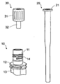
- FIG. 3 is a perspective view showing three parts constituting the plug according to the first embodiment of the present invention with the suction straw removed from the state of FIG.
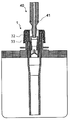
- FIG. 4 is an explanatory cross-sectional view schematically showing a state in which the plug according to the first embodiment of the present invention is attached to a container.
- FIG. 5 is an explanatory cross-sectional view schematically showing a state in which a suction plug is to be inserted into the plug according to the first embodiment of the present invention.
- FIG. 1 is a perspective view showing a plug according to a first embodiment of the present invention.
- FIG. 2 is a perspective view showing a state where a cap is removed from the state of FIG.
- FIG. 3 is a perspective view showing three parts constituting the plug according to the first embodiment of the present invention with the su
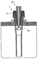
- FIG. 6 is an explanatory cross-sectional view schematically showing a state in which the movable valve is opened by completely inserting the suction plug from the state of FIG.
- FIG. 7 is an explanatory cross-sectional view schematically showing a state in which another embodiment of the plug according to the first embodiment of the present invention is attached to a container.
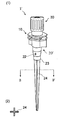
- (1) of FIG. 8 is a perspective view showing a plug according to a second embodiment of the present invention.
- (2) of FIG. 8 is a schematic cross-sectional view showing the AA ′ cross section of (1) of FIG.
- FIG. 9 is a perspective view showing a state where the cap is removed from the state of FIG. FIG.
- FIG. 10 is a perspective view showing three parts constituting the plug according to the second embodiment of the present invention with the suction straw removed from the state of FIG.
- FIG. 11 is an explanatory cross-sectional view schematically showing a state in which the plug according to the second embodiment of the present invention is attached to a container.
- FIG. 12 is an explanatory cross-sectional view schematically showing a state in which a suction plug is to be inserted into the plug according to the second embodiment of the present invention.
- FIG. 13 is a sectional explanatory view schematically showing a state in which the movable valve is opened by completely inserting the suction plug from the state of FIG. FIG.
- FIG. 14 is an explanatory cross-sectional view schematically showing a state in which another embodiment of the plug according to the second embodiment of the present invention is attached to a container.
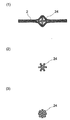
- FIG. 15A is an explanatory cross-sectional view illustrating the operation and effect of the blocking prevention column.
- FIGS. 15 (2) and 15 (3) are schematic cross-sectional views showing examples of other cross-sectional shapes of the blockage prevention column.
- FIG. 1 is a perspective view showing a plug 1 according to a first embodiment of the present invention.
- FIG. 2 is a perspective view showing a state where the cap 30 is removed from the state of FIG.
- FIG. 3 shows a state in which the suction straw 20 is removed from the state of FIG. 2, and the three parts constituting the plug 1 according to the first embodiment of the present invention, namely, the plug main body 10, the suction straw 20, and the cap 30 are removed. It is the perspective view shown.
- FIG. 1 is a perspective view showing a plug 1 according to a first embodiment of the present invention.
- FIG. 2 is a perspective view showing a state where the cap 30 is removed from the state of FIG.
- FIG. 3 shows a state in which the suction straw 20 is removed from the state of FIG. 2, and the three parts constituting the plug 1 according to the first embodiment of the present invention, namely, the plug main body 10, the suction straw 20, and the cap 30 are removed. It is the perspective view shown.
- FIG. 1 is a perspective view
- FIG. 4 is an explanatory cross-sectional view schematically showing a state in which the plug 1 according to the first embodiment of the present invention is attached to the container 2 (a container for discharging a suction content).
- the up-down direction in a state where the suction content discharging container is erected is defined as up and down.
- the plug 1 is a plug made of a synthetic resin used by being attached to the opening of the container 2, and includes a plug main body 10, a suction straw 20, and a cap 30. You.
- the plug body 10 includes a cylindrical outer cylinder 11 having an external thread 14 into which the cap 30 is screwed, a flange portion 12 for holding the entire plug, and a welding portion for welding to the opening of the container 2. 13 are integrally formed.
- the suction straw 20 has a cylindrical pipe portion fitted to the inner periphery of the outer cylinder 11 of the plug body 10, and the lowermost portion (one end) reaches the bottom surface of the container 2 in a state where the suction straw 20 is attached to the container.
- the tube portion of the suction straw 20 extends from the lowermost portion to the uppermost portion.
- the cap 30 is fitted on the inner periphery of the suction straw 20 with a screw portion 31 having an internal thread which is screwed to the external thread 14 provided on the outer cylinder 11 of the plug body 10, and for sucking the contents. And a movable valve 33 that is slidable in the axial direction on the inner periphery of the inner cylinder 32.
- the movable valve 33 closes the opening at the tip of the inner cylinder 32 when the suction plug 40 is not inserted, and as shown in FIG. 6, the suction plug 40 is inserted.
- the distal end of the inner cylinder 32 is opened by elastically engaging with the distal end of the suction plug and sliding on the inner periphery of the inner cylinder 32.
- the movable valve 33 moves to the original position together with the suction plug 40 because the movable valve 33 is engaged with the front end of the suction plug 40, and the opening at the front end of the inner cylinder 32 is opened. Close the part again. That is, the container 2 can be resealed and reopened.
- the collar 21 of the suction straw 20 and the cap 30 are sealed by a contact ring 34 provided inside the uppermost portion of the cap.
- the flange 21 of the suction straw 20 and the cap 30 are connected by a perforated disk-shaped elastic packing 35a inserted inside the uppermost part of the cap 30.
- the collar of the suction straw 20 and the plug main body 10 are hermetically sealed by a perforated disk-shaped elastic packing 35b arranged at the uppermost part of the plug main body.
- Various rubber materials can be used for the elastic packings 35a and 35b.
- a filling nozzle having the same shape as the suction plug 40 is inserted into the plug. 6, filling can be performed with the movable valve 33 opened.
- polyolefin resins such as low density polyethylene resin (LDPE), high density polyethylene resin (HDPE), linear low density polyethylene resin (LLDPE), polypropylene resin (PP), polyolefin elastomer, and polyethylene terephthalate Polyester resin such as resin (PET), polybutylene terephthalate resin (PBT), polyethylene naphthalate resin (PEN), polymethyl methacrylate resin (PMMA), polyacrylonitrile resin, ABS resin, nylon-6, nylon-66
- PET low density polyethylene resin
- PBT polybutylene terephthalate resin
- PEN polyethylene naphthalate resin
- PMMA polymethyl methacrylate resin
- polyacrylonitrile resin ABS resin
- nylon-6 nylon-6
- nylon-66 Such as polyamide resin, polystyrene resin (PS), polyvinyl chloride resin (PVC), polyvinylidene chloride resin (PVDC), polycarbonate resin (PC), polyacetal resin, polysulfone resin, fluor
- PE polyethylene
- the material of the suction straw 20 is a soft LDPE resin having a packing property. It is preferable to use a material having a flexural modulus of less than 200 MPa, such as an LLDPE resin or a copolymer thereof.
- the material of the suction straw 20 is not only PE resin but also PP. Hard materials such as resin and ABS resin can also be used. In this case, it is preferable to insert an elastic packing 35b between the suction straw 20 and the plug body 10 in order to seal the two.
- the spout 1 has a relatively simple structure including a small number of parts, but can be used by suction, and can be opened and resealed by the action of the movable valve 33. is there.
- the number of components is small, and all the components can be molded with a general-purpose synthetic resin, it can be manufactured at low cost.
- the container for discharging the suction contents provided with the plug 1 can be preferably used particularly as a container for supplying ink to a printing machine or a copying machine.
- the faucet 1 ' can be easily used for containers of various sizes because other parts can be used in common simply by adjusting the length of the suction straw 20 according to the size of the container 2. It is.
- FIG. 8A is a perspective view showing a plug 1 ′ according to a second embodiment of the present invention.
- FIG. 8B is a schematic cross-sectional view showing a cross section taken along the line BB ′ of FIG.
- FIG. 9 is a perspective view showing a state where the cap 30 is removed from the state of FIG.
- FIG. 10 shows a state in which the suction straw 20 ′ is removed from the state of FIG. 9 and three parts constituting the plug 1 ′ according to the second embodiment of the present invention, namely, the plug main body 10, the suction straw 20 ′
- FIG. 2 is a perspective view showing a cap 30.
- FIG. 11 is an explanatory cross-sectional view schematically showing a state in which the plug 1 'according to the second embodiment of the present invention is attached to the container 2 (a container for discharging the contents of suction).
- the up-down direction in a state where the suction content discharging container is erected is defined as up and down.
- the plug 1 ′ according to the second embodiment of the present invention is a plug made of a synthetic resin which is used by being attached to an opening of a flexible container 2, and includes a plug main body 10 and a suction straw 20 ′. And a cap 30.
- the plug body 10 includes a cylindrical outer cylinder 11 having an external thread 14 into which the cap 30 is screwed, a flange portion 12 for holding the entire plug, and a welding portion for welding to the opening of the container 2. 13 are integrally formed.
- the suction straw 20 ′ has a lower end 23, which is a cylindrical pipe portion fitted to the inner periphery of the outer cylinder 11 of the plug body 10, and is provided at the uppermost part for locking the uppermost part of the outer cylinder 11. It has a collar 21.
- a tapered vertical-shaped obstruction prevention column 24 having a cross-sectional shape (irregular cross-section) in which a gap is formed between the container 2 and the container 2 extends.
- the lower end 23 of the suction straw 20 ' is provided with an air hole 22 for sucking air in the container.
- the length of the anti-blocking column 24 according to the size of the container, it can be applied to containers of various sizes.
- the bottom part does not need to reach the bottom vicinity of a container, and the blockage prevention pillar 24 does not need to reach
- the blocking prevention column 24 has an irregular cross section, a gap is formed between the lower end 23 of the suction straw 20 ′ and the content liquid. Therefore, the content liquid can be sucked from this gap. Further, as shown in (1) of FIG. 15, the blocking prevention column 24 forms a gap between itself and the container 2, so that the content liquid can be sucked without being closed.
- the blockage prevention column 24 has a cross shape, but as shown in (2) of FIG. 15 and (3) of FIG. If so, the sectional shape is not particularly limited.
- the blocking prevention column 24 is fitted as a separate component to the lower end 23 of the suction straw 20 ', but may be formed integrally with the suction straw 20'.
- the diameter of the air hole 22 is suitably about 1 mm to 5 mm.
- the cap 30 is fitted on a screw portion 31 having an internal thread on the inner periphery thereof, which is screwed to the male screw 14 provided on the outer cylinder 11 of the plug body 10, and on the inner periphery of the suction straw 20 'to suck the contents.
- a movable valve 33 slidable in the axial direction on the inner periphery of the inner cylinder 32.
- the movable valve 33 closes the opening at the tip of the inner cylinder 32. As shown in FIG. 12, when the suction plug 40 is not inserted, the movable valve 33 closes the opening at the tip of the inner cylinder 32. As shown in FIG. When this occurs, the distal end of the inner cylinder 32 is opened by elastically engaging with the distal end of the suction plug and sliding on the inner periphery of the inner cylinder 32.
- the movable valve 33 moves to the original position together with the suction plug 40 because the movable valve 33 is engaged with the front end of the suction plug 40, and the movable valve 33 moves to the original position. Close the opening again. That is, the container can be resealed and reopened.
- the collar 21 of the suction straw 20 'and the cap 30 are sealed by a contact ring 34 provided inside the top of the cap.
- the collar 21 of the suction straw 20 ′ and the cap 30 are a perforated disk-shaped elastic packing inserted inside the uppermost part of the cap 30.
- the collar of the suction straw 20 'and the plug body 10 are sealed by a perforated disk-shaped elastic packing 35b arranged at the top of the plug body.
- Various rubber materials can be used for the elastic packings 35a and 35b.
- a filling nozzle having the same shape as the suction plug 40 is inserted into the plug, Filling can be performed with the movable valve 33 open, as shown in FIG.
- the lower end 23 of the suction straw 20 ′ has an opening for sucking the contents, and the contents liquid is sucked from this opening, In addition to being able to supply a large amount of content liquid, when air is present inside the container, the air is preferentially sucked, so that the same effect as the air hole 22 is exhibited.
- polyolefin resins such as low density polyethylene resin (LDPE), high density polyethylene resin (HDPE), linear low density polyethylene resin (LLDPE), polypropylene resin (PP), polyolefin elastomer, and polyethylene terephthalate Polyester resin such as resin (PET), polybutylene terephthalate resin (PBT), polyethylene naphthalate resin (PEN), polymethyl methacrylate resin (PMMA), polyacrylonitrile resin, ABS resin, nylon-6, nylon-66 Polyamide resin, polystyrene resin (PS), polyvinyl chloride resin (PVC), polyvinylidene chloride resin (PVDC), polycarbonate resin (PC), polyacetal resin, polysulfone resin, fluorine rubber A silicon rubber, Teflon (registered trademark) packing and the like.
- LDPE low density polyethylene resin
- HDPE high density polyethylene resin
- LLDPE linear low density polyethylene resin
- PP polypropylene resin
- PMMA polymethyl meth
- a polyethylene (PE) resin is used for the plug body 10, the suction straw 20 ', and the movable valve 33, and a harder PP resin is used for the cap 30. good.
- the material of the suction straw 20' is a soft material having packing property. It is preferable to use a material having a flexural modulus of less than 200 MPa, such as an LDPE resin, an LLDPE resin, or a copolymer thereof.
- the material of the suction straw 20' may be other than PE resin. Hard materials such as PP resin, ABS resin and the like can also be used. In this case, it is desirable to insert an elastic packing 35b between the suction straw 20 'and the plug body 10 in order to seal the two.
- the suction straw 20 'and the blockage prevention column 24 may be integrally formed or may be separate parts.
- the plug 1 ’ has a relatively simple structure including a small number of components, but can be used by suction, and can be opened and resealed by the operation of the movable valve 33.
- the provision of the blocking prevention column 24 having a gap with the container 2 prevents the suction straw 20 'from closing even when the residual liquid is reduced. For this reason, it became possible to minimize the amount of the residual liquid remaining in the container 2 without being sucked.
- the plug 1 ′ can be used in common with other components simply by adjusting the length of the blocking prevention column 24 according to the size of the container 2, it can be used for containers of various sizes. It is easily possible.
- the air hole 22 for sucking the air in the container is provided at the lower end of the suction straw 20 ', the air existing in the upper part of the container 2 is sucked preferentially at the start of suction, and the air disappears. Since the supply of the content liquid is started at the point in time, stable liquid supply without air biting can be achieved.
- the suction amount can be increased, and in addition to exhibiting the same effect as the air hole 22 provided at the lower end, there is no air bite. Stable liquid supply becomes possible.
- the suction contents discharging container provided with the plug 1 ’ can be preferably used particularly as a container for supplying ink to a printing machine or a copying machine. Particularly, in the case of expensive contents, it meets the demand for using the last drop without waste.
- Example 1 A plug having a structure as shown in FIGS. 8 to 11 was prepared.
- the material of each part was made of polyethylene resin for the plug body, suction straw and blockage prevention column, and polypropylene resin for the cap.
- the inner diameter of the suction straw was 12 mm, and the total length was 10 mm for the short pipe portion and 100 mm for the column for preventing blockage, which was the length below the movable valve.
- the spout was welded to the opening of a soft pouch having a top and bottom dimension of 225 mm, a width of 200 mm, and a capacity of 1 liter to obtain a container for discharging a suction content. This container was filled with 1 liter of water as a content liquid. Water was sucked from the suction plug inserted in the plug, and the amount of residual liquid was measured.
- Example 2 As Example 2, a container for dispensing suction contents was prepared using a plug that does not use a blockage prevention column as shown in FIG. 1 and evaluated similarly. The length of the suction straw was 110 mm as the length below the movable valve.
- Comparative Example 1 As Comparative Example 1, a suction content discharging container was prepared and evaluated in the same manner as in Example 1, except that the length of the suction straw was set to 50 mm below the movable valve. Table 1 summarizes the above results.
- the residual liquid was 30 ml, whereas the port of Example 1 which was the plug according to the second embodiment.
- the residual liquid was 8 ml. Thereby, it was confirmed that the remaining liquid can be reduced by providing the blocking prevention column.
- the length of the suction straw was absolutely insufficient, and the container using the plug of Comparative Example 1 which was not provided with the clogging prevention column was blocked by the plug, and the residual liquid amounted to 50 ml.
- the present invention can be used for packaging containers.
Landscapes
- Engineering & Computer Science (AREA)
- Mechanical Engineering (AREA)
- Closures For Containers (AREA)
Abstract
L'invention concerne un bouchon permettant d'extraire, par aspiration, le contenu de la partie supérieure d'un récipient, et pouvant, en outre, être refermé hermétiquement. L'invention concerne donc un bouchon utilisé par fixation à une ouverture d'un récipient, le bouchon étant caractérisé en ce que : le bouchon se compose d'un corps de bouchon, d'une paille d'aspiration et d'un capuchon ; le corps de bouchon est tel qu'une partie soudure, une partie bride et un tube externe cylindrique comprenant un filetage mâle sur lequel le capuchon est monté par vissage, sont moulés en une seule pièce ; la paille d'aspiration comporte une partie tuyau cylindrique qui est insérée dans la périphérie interne du tube externe du corps du bouchon, et une partie rebord destinée à venir en contact avec la partie supérieure du tube externe ; le capuchon comporte une partie filetée dans laquelle un filetage femelle est disposé sur la périphérie interne, le filetage femelle étant monté par vissage sur le filetage mâle prévu sur le tube externe du corps de bouchon, et comporte également un tube interne ; et une valve mobile pouvant coulisser axialement dans la périphérie interne du tube interne est disposée à l'intérieur du tube interne.
Priority Applications (1)
| Application Number | Priority Date | Filing Date | Title |
|---|---|---|---|
| CN201980043541.3A CN112368219A (zh) | 2018-07-06 | 2019-07-05 | 口栓 |
Applications Claiming Priority (4)
| Application Number | Priority Date | Filing Date | Title |
|---|---|---|---|
| JP2018-129117 | 2018-07-06 | ||
| JP2018129117A JP7163643B2 (ja) | 2018-07-06 | 2018-07-06 | 口栓 |
| JP2019004326A JP7131399B2 (ja) | 2019-01-15 | 2019-01-15 | 口栓 |
| JP2019-004326 | 2019-01-15 |
Publications (1)
| Publication Number | Publication Date |
|---|---|
| WO2020009233A1 true WO2020009233A1 (fr) | 2020-01-09 |
Family
ID=69059237
Family Applications (1)
| Application Number | Title | Priority Date | Filing Date |
|---|---|---|---|
| PCT/JP2019/026853 Ceased WO2020009233A1 (fr) | 2018-07-06 | 2019-07-05 | Bouchon |
Country Status (2)
| Country | Link |
|---|---|
| CN (1) | CN112368219A (fr) |
| WO (1) | WO2020009233A1 (fr) |
Citations (4)
| Publication number | Priority date | Publication date | Assignee | Title |
|---|---|---|---|---|
| JPS59186261U (ja) * | 1983-05-28 | 1984-12-11 | 東罐興業株式会社 | 複合式容器の吸引管 |
| JPS6376653U (fr) * | 1986-06-10 | 1988-05-21 | ||
| JPH1072044A (ja) * | 1996-07-04 | 1998-03-17 | Mikuni Plast Kk | 食品容器 |
| JP2016216073A (ja) * | 2015-05-18 | 2016-12-22 | 凸版印刷株式会社 | 口栓構造、ノズル |
Family Cites Families (6)
| Publication number | Priority date | Publication date | Assignee | Title |
|---|---|---|---|---|
| JP3222681B2 (ja) * | 1994-02-10 | 2001-10-29 | 株式会社吉野工業所 | ポンプ容器 |
| JP3565450B2 (ja) * | 1995-05-12 | 2004-09-15 | 株式会社吉野工業所 | 液体注出ポンプ |
| JP4006332B2 (ja) * | 2002-12-26 | 2007-11-14 | 勝利 増田 | 流動体貯留容器 |
| KR20030014304A (ko) * | 2003-01-13 | 2003-02-15 | 이정민 | 내용물 흡배출용 스트로를 수용하도록 된 액체용기 |
| JP2016222252A (ja) * | 2015-05-27 | 2016-12-28 | 凸版印刷株式会社 | 口栓 |
| JP2018020841A (ja) * | 2016-07-25 | 2018-02-08 | フジモリプラケミカル株式会社 | 液体収納袋 |
-
2019
- 2019-07-05 CN CN201980043541.3A patent/CN112368219A/zh active Pending
- 2019-07-05 WO PCT/JP2019/026853 patent/WO2020009233A1/fr not_active Ceased
Patent Citations (4)
| Publication number | Priority date | Publication date | Assignee | Title |
|---|---|---|---|---|
| JPS59186261U (ja) * | 1983-05-28 | 1984-12-11 | 東罐興業株式会社 | 複合式容器の吸引管 |
| JPS6376653U (fr) * | 1986-06-10 | 1988-05-21 | ||
| JPH1072044A (ja) * | 1996-07-04 | 1998-03-17 | Mikuni Plast Kk | 食品容器 |
| JP2016216073A (ja) * | 2015-05-18 | 2016-12-22 | 凸版印刷株式会社 | 口栓構造、ノズル |
Also Published As
| Publication number | Publication date |
|---|---|
| CN112368219A (zh) | 2021-02-12 |
Similar Documents
| Publication | Publication Date | Title |
|---|---|---|
| US20200062464A1 (en) | Coupled structure between pouring spout of refill container and pouring unit of packaging container | |
| US10961025B2 (en) | Pouring spout of container | |
| WO2020009233A1 (fr) | Bouchon | |
| JP7131399B2 (ja) | 口栓 | |
| JP7268380B2 (ja) | 口栓 | |
| JP7263786B2 (ja) | 口栓 | |
| JP7163643B2 (ja) | 口栓 | |
| JP7321647B2 (ja) | バリアキャップ | |
| CN101990513B (zh) | 流体容器 | |
| JP7172202B2 (ja) | 口栓 | |
| JP7195846B2 (ja) | 付替用注出栓および注出栓付きパウチ容器包装体 | |
| JP6990543B2 (ja) | 吐出容器 | |
| JP7257733B2 (ja) | 注出キャップ及び注出容器 | |
| JP4954695B2 (ja) | 詰め替え用容器 | |
| JP6458544B2 (ja) | 口栓 | |
| JP7082483B2 (ja) | 二重容器 | |
| JP5542462B2 (ja) | 詰め替え容器 | |
| JP7703389B2 (ja) | ヒンジキャップ | |
| US10173810B2 (en) | Caps and adapters for containers | |
| JP6391968B2 (ja) | 逆止弁付き注出栓 | |
| CA2964285C (fr) | Recipient pourvu d'un element de tete d'une seule piece | |
| JP7709506B2 (ja) | 二重容器用注出キャップ及び二重容器 | |
| JP2019172291A (ja) | 吐出容器 | |
| JP7466171B2 (ja) | 注出具および包装容器 | |
| JP6850602B2 (ja) | 詰め替え容器 |
Legal Events
| Date | Code | Title | Description |
|---|---|---|---|
| 121 | Ep: the epo has been informed by wipo that ep was designated in this application |
Ref document number: 19831267 Country of ref document: EP Kind code of ref document: A1 |
|
| NENP | Non-entry into the national phase |
Ref country code: DE |
|
| 122 | Ep: pct application non-entry in european phase |
Ref document number: 19831267 Country of ref document: EP Kind code of ref document: A1 |