WO2020009233A1 - 口栓 - Google Patents
口栓 Download PDFInfo
- Publication number
- WO2020009233A1 WO2020009233A1 PCT/JP2019/026853 JP2019026853W WO2020009233A1 WO 2020009233 A1 WO2020009233 A1 WO 2020009233A1 JP 2019026853 W JP2019026853 W JP 2019026853W WO 2020009233 A1 WO2020009233 A1 WO 2020009233A1
- Authority
- WO
- WIPO (PCT)
- Prior art keywords
- suction
- plug
- container
- cap
- straw
- Prior art date
- Legal status (The legal status is an assumption and is not a legal conclusion. Google has not performed a legal analysis and makes no representation as to the accuracy of the status listed.)
- Ceased
Links
Images





Classifications
-
- B—PERFORMING OPERATIONS; TRANSPORTING
- B65—CONVEYING; PACKING; STORING; HANDLING THIN OR FILAMENTARY MATERIAL
- B65D—CONTAINERS FOR STORAGE OR TRANSPORT OF ARTICLES OR MATERIALS, e.g. BAGS, BARRELS, BOTTLES, BOXES, CANS, CARTONS, CRATES, DRUMS, JARS, TANKS, HOPPERS, FORWARDING CONTAINERS; ACCESSORIES, CLOSURES, OR FITTINGS THEREFOR; PACKAGING ELEMENTS; PACKAGES
- B65D75/00—Packages comprising articles or materials partially or wholly enclosed in strips, sheets, blanks, tubes or webs of flexible sheet material, e.g. in folded wrappers
- B65D75/52—Details
- B65D75/58—Opening or contents-removing devices added or incorporated during package manufacture
Definitions
- the present invention relates to a spout for sucking and attaching to a container for storing liquid or powder, which can be re-opened and re-closed with a relatively simple structure, has high sealing properties, and has a high sealing property.
- the present invention relates to a spout that requires less residual liquid.
- a container for storing liquid or powder a container called a pouch with a plug, in which a plug is attached to a flexible bag-like container, is known.
- a pouch with a spout does not use the entire contents at once, but even when used for dispensing, the container shrinks according to the amount used, so the contents do not touch the air to the end It has the advantage that it can be used.
- Patent Literature 2 The plug structure and nozzle described in Patent Literature 2 are plugs used for the pouch with the plug, and have dimensions of an inner peripheral surface of a plug and a head of a male member in a conventional plug (Patent Literature 1).
- the accuracy requirement was very high, and it could not be adopted for inexpensive items such as disposable containers. It was intended to solve the problem of difficulty in responding.
- Conventional pouches with a spout generally have a method in which a bag is attached to a predetermined server and the contents are naturally dropped out of a spout attached to a lower part of the bag.
- the plug described in Patent Document 2 has a similar structure.
- the problem to be solved by the present invention is to propose a plug capable of discharging the contents by suction from the upper part of the container and which can be resealed.
- a synthetic resin plug used by being attached to an opening of a container, comprising a plug main body, a suction straw, and a cap.
- a cylindrical outer cylinder provided with a male screw to which the cap is screwed, a flange portion for holding the entire plug, and a welded portion for welding to the opening of the container, are integrally formed
- the suction straw has a cylindrical tube portion fitted to the inner periphery of the outer cylinder of the plug body, and a collar portion for locking to the outer cylinder, and the cap is provided on the outer cylinder of the plug body.
- a movable valve slidable in the axial direction on the inner circumference of the inner cylinder is provided inside the cylinder, and the movable valve has a suction plug.
- the container has flexibility
- the suction straw has a tapered vertical body having a cross-sectional shape in which a gap is formed between the container and the container when the contents of the container are suctioned from one end of the tube portion by the suction plug.
- the pipe portion may be provided with an air hole capable of sucking air in the container.
- the collar of the suction straw and the cap may be sealed by a contact ring provided inside the top of the cap.
- the collar of the suction straw and the cap may be sealed by an elastic packing inserted inside the top of the cap.
- Another aspect of the present invention is a suction content discharging container provided with the above-mentioned plug.
- the spout according to the present invention has a relatively simple structure composed of a small number of components, such as a spout main body, a suction straw and a cap, but can be used for suction which was impossible with a conventional spout. Opening and resealing became possible by the action of the movable valve.
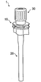
- FIG. 1 is a perspective view showing a plug according to a first embodiment of the present invention.
- FIG. 2 is a perspective view showing a state where a cap is removed from the state of FIG.
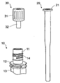
- FIG. 3 is a perspective view showing three parts constituting the plug according to the first embodiment of the present invention with the suction straw removed from the state of FIG.
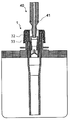
- FIG. 4 is an explanatory cross-sectional view schematically showing a state in which the plug according to the first embodiment of the present invention is attached to a container.
- FIG. 5 is an explanatory cross-sectional view schematically showing a state in which a suction plug is to be inserted into the plug according to the first embodiment of the present invention.
- FIG. 1 is a perspective view showing a plug according to a first embodiment of the present invention.
- FIG. 2 is a perspective view showing a state where a cap is removed from the state of FIG.
- FIG. 3 is a perspective view showing three parts constituting the plug according to the first embodiment of the present invention with the su
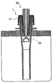
- FIG. 6 is an explanatory cross-sectional view schematically showing a state in which the movable valve is opened by completely inserting the suction plug from the state of FIG.
- FIG. 7 is an explanatory cross-sectional view schematically showing a state in which another embodiment of the plug according to the first embodiment of the present invention is attached to a container.
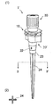
- (1) of FIG. 8 is a perspective view showing a plug according to a second embodiment of the present invention.
- (2) of FIG. 8 is a schematic cross-sectional view showing the AA ′ cross section of (1) of FIG.
- FIG. 9 is a perspective view showing a state where the cap is removed from the state of FIG. FIG.
- FIG. 10 is a perspective view showing three parts constituting the plug according to the second embodiment of the present invention with the suction straw removed from the state of FIG.
- FIG. 11 is an explanatory cross-sectional view schematically showing a state in which the plug according to the second embodiment of the present invention is attached to a container.
- FIG. 12 is an explanatory cross-sectional view schematically showing a state in which a suction plug is to be inserted into the plug according to the second embodiment of the present invention.
- FIG. 13 is a sectional explanatory view schematically showing a state in which the movable valve is opened by completely inserting the suction plug from the state of FIG. FIG.
- FIG. 14 is an explanatory cross-sectional view schematically showing a state in which another embodiment of the plug according to the second embodiment of the present invention is attached to a container.
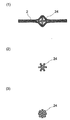
- FIG. 15A is an explanatory cross-sectional view illustrating the operation and effect of the blocking prevention column.
- FIGS. 15 (2) and 15 (3) are schematic cross-sectional views showing examples of other cross-sectional shapes of the blockage prevention column.
- FIG. 1 is a perspective view showing a plug 1 according to a first embodiment of the present invention.
- FIG. 2 is a perspective view showing a state where the cap 30 is removed from the state of FIG.
- FIG. 3 shows a state in which the suction straw 20 is removed from the state of FIG. 2, and the three parts constituting the plug 1 according to the first embodiment of the present invention, namely, the plug main body 10, the suction straw 20, and the cap 30 are removed. It is the perspective view shown.
- FIG. 1 is a perspective view showing a plug 1 according to a first embodiment of the present invention.
- FIG. 2 is a perspective view showing a state where the cap 30 is removed from the state of FIG.
- FIG. 3 shows a state in which the suction straw 20 is removed from the state of FIG. 2, and the three parts constituting the plug 1 according to the first embodiment of the present invention, namely, the plug main body 10, the suction straw 20, and the cap 30 are removed. It is the perspective view shown.
- FIG. 1 is a perspective view
- FIG. 4 is an explanatory cross-sectional view schematically showing a state in which the plug 1 according to the first embodiment of the present invention is attached to the container 2 (a container for discharging a suction content).
- the up-down direction in a state where the suction content discharging container is erected is defined as up and down.
- the plug 1 is a plug made of a synthetic resin used by being attached to the opening of the container 2, and includes a plug main body 10, a suction straw 20, and a cap 30. You.
- the plug body 10 includes a cylindrical outer cylinder 11 having an external thread 14 into which the cap 30 is screwed, a flange portion 12 for holding the entire plug, and a welding portion for welding to the opening of the container 2. 13 are integrally formed.
- the suction straw 20 has a cylindrical pipe portion fitted to the inner periphery of the outer cylinder 11 of the plug body 10, and the lowermost portion (one end) reaches the bottom surface of the container 2 in a state where the suction straw 20 is attached to the container.
- the tube portion of the suction straw 20 extends from the lowermost portion to the uppermost portion.
- the cap 30 is fitted on the inner periphery of the suction straw 20 with a screw portion 31 having an internal thread which is screwed to the external thread 14 provided on the outer cylinder 11 of the plug body 10, and for sucking the contents. And a movable valve 33 that is slidable in the axial direction on the inner periphery of the inner cylinder 32.
- the movable valve 33 closes the opening at the tip of the inner cylinder 32 when the suction plug 40 is not inserted, and as shown in FIG. 6, the suction plug 40 is inserted.
- the distal end of the inner cylinder 32 is opened by elastically engaging with the distal end of the suction plug and sliding on the inner periphery of the inner cylinder 32.
- the movable valve 33 moves to the original position together with the suction plug 40 because the movable valve 33 is engaged with the front end of the suction plug 40, and the opening at the front end of the inner cylinder 32 is opened. Close the part again. That is, the container 2 can be resealed and reopened.
- the collar 21 of the suction straw 20 and the cap 30 are sealed by a contact ring 34 provided inside the uppermost portion of the cap.
- the flange 21 of the suction straw 20 and the cap 30 are connected by a perforated disk-shaped elastic packing 35a inserted inside the uppermost part of the cap 30.
- the collar of the suction straw 20 and the plug main body 10 are hermetically sealed by a perforated disk-shaped elastic packing 35b arranged at the uppermost part of the plug main body.
- Various rubber materials can be used for the elastic packings 35a and 35b.
- a filling nozzle having the same shape as the suction plug 40 is inserted into the plug. 6, filling can be performed with the movable valve 33 opened.
- polyolefin resins such as low density polyethylene resin (LDPE), high density polyethylene resin (HDPE), linear low density polyethylene resin (LLDPE), polypropylene resin (PP), polyolefin elastomer, and polyethylene terephthalate Polyester resin such as resin (PET), polybutylene terephthalate resin (PBT), polyethylene naphthalate resin (PEN), polymethyl methacrylate resin (PMMA), polyacrylonitrile resin, ABS resin, nylon-6, nylon-66
- PET low density polyethylene resin
- PBT polybutylene terephthalate resin
- PEN polyethylene naphthalate resin
- PMMA polymethyl methacrylate resin
- polyacrylonitrile resin ABS resin
- nylon-6 nylon-6
- nylon-66 Such as polyamide resin, polystyrene resin (PS), polyvinyl chloride resin (PVC), polyvinylidene chloride resin (PVDC), polycarbonate resin (PC), polyacetal resin, polysulfone resin, fluor
- PE polyethylene
- the material of the suction straw 20 is a soft LDPE resin having a packing property. It is preferable to use a material having a flexural modulus of less than 200 MPa, such as an LLDPE resin or a copolymer thereof.
- the material of the suction straw 20 is not only PE resin but also PP. Hard materials such as resin and ABS resin can also be used. In this case, it is preferable to insert an elastic packing 35b between the suction straw 20 and the plug body 10 in order to seal the two.
- the spout 1 has a relatively simple structure including a small number of parts, but can be used by suction, and can be opened and resealed by the action of the movable valve 33. is there.
- the number of components is small, and all the components can be molded with a general-purpose synthetic resin, it can be manufactured at low cost.
- the container for discharging the suction contents provided with the plug 1 can be preferably used particularly as a container for supplying ink to a printing machine or a copying machine.
- the faucet 1 ' can be easily used for containers of various sizes because other parts can be used in common simply by adjusting the length of the suction straw 20 according to the size of the container 2. It is.
- FIG. 8A is a perspective view showing a plug 1 ′ according to a second embodiment of the present invention.
- FIG. 8B is a schematic cross-sectional view showing a cross section taken along the line BB ′ of FIG.
- FIG. 9 is a perspective view showing a state where the cap 30 is removed from the state of FIG.
- FIG. 10 shows a state in which the suction straw 20 ′ is removed from the state of FIG. 9 and three parts constituting the plug 1 ′ according to the second embodiment of the present invention, namely, the plug main body 10, the suction straw 20 ′
- FIG. 2 is a perspective view showing a cap 30.
- FIG. 11 is an explanatory cross-sectional view schematically showing a state in which the plug 1 'according to the second embodiment of the present invention is attached to the container 2 (a container for discharging the contents of suction).
- the up-down direction in a state where the suction content discharging container is erected is defined as up and down.
- the plug 1 ′ according to the second embodiment of the present invention is a plug made of a synthetic resin which is used by being attached to an opening of a flexible container 2, and includes a plug main body 10 and a suction straw 20 ′. And a cap 30.
- the plug body 10 includes a cylindrical outer cylinder 11 having an external thread 14 into which the cap 30 is screwed, a flange portion 12 for holding the entire plug, and a welding portion for welding to the opening of the container 2. 13 are integrally formed.
- the suction straw 20 ′ has a lower end 23, which is a cylindrical pipe portion fitted to the inner periphery of the outer cylinder 11 of the plug body 10, and is provided at the uppermost part for locking the uppermost part of the outer cylinder 11. It has a collar 21.
- a tapered vertical-shaped obstruction prevention column 24 having a cross-sectional shape (irregular cross-section) in which a gap is formed between the container 2 and the container 2 extends.
- the lower end 23 of the suction straw 20 ' is provided with an air hole 22 for sucking air in the container.
- the length of the anti-blocking column 24 according to the size of the container, it can be applied to containers of various sizes.
- the bottom part does not need to reach the bottom vicinity of a container, and the blockage prevention pillar 24 does not need to reach
- the blocking prevention column 24 has an irregular cross section, a gap is formed between the lower end 23 of the suction straw 20 ′ and the content liquid. Therefore, the content liquid can be sucked from this gap. Further, as shown in (1) of FIG. 15, the blocking prevention column 24 forms a gap between itself and the container 2, so that the content liquid can be sucked without being closed.
- the blockage prevention column 24 has a cross shape, but as shown in (2) of FIG. 15 and (3) of FIG. If so, the sectional shape is not particularly limited.
- the blocking prevention column 24 is fitted as a separate component to the lower end 23 of the suction straw 20 ', but may be formed integrally with the suction straw 20'.
- the diameter of the air hole 22 is suitably about 1 mm to 5 mm.
- the cap 30 is fitted on a screw portion 31 having an internal thread on the inner periphery thereof, which is screwed to the male screw 14 provided on the outer cylinder 11 of the plug body 10, and on the inner periphery of the suction straw 20 'to suck the contents.
- a movable valve 33 slidable in the axial direction on the inner periphery of the inner cylinder 32.
- the movable valve 33 closes the opening at the tip of the inner cylinder 32. As shown in FIG. 12, when the suction plug 40 is not inserted, the movable valve 33 closes the opening at the tip of the inner cylinder 32. As shown in FIG. When this occurs, the distal end of the inner cylinder 32 is opened by elastically engaging with the distal end of the suction plug and sliding on the inner periphery of the inner cylinder 32.
- the movable valve 33 moves to the original position together with the suction plug 40 because the movable valve 33 is engaged with the front end of the suction plug 40, and the movable valve 33 moves to the original position. Close the opening again. That is, the container can be resealed and reopened.
- the collar 21 of the suction straw 20 'and the cap 30 are sealed by a contact ring 34 provided inside the top of the cap.
- the collar 21 of the suction straw 20 ′ and the cap 30 are a perforated disk-shaped elastic packing inserted inside the uppermost part of the cap 30.
- the collar of the suction straw 20 'and the plug body 10 are sealed by a perforated disk-shaped elastic packing 35b arranged at the top of the plug body.
- Various rubber materials can be used for the elastic packings 35a and 35b.
- a filling nozzle having the same shape as the suction plug 40 is inserted into the plug, Filling can be performed with the movable valve 33 open, as shown in FIG.
- the lower end 23 of the suction straw 20 ′ has an opening for sucking the contents, and the contents liquid is sucked from this opening, In addition to being able to supply a large amount of content liquid, when air is present inside the container, the air is preferentially sucked, so that the same effect as the air hole 22 is exhibited.
- polyolefin resins such as low density polyethylene resin (LDPE), high density polyethylene resin (HDPE), linear low density polyethylene resin (LLDPE), polypropylene resin (PP), polyolefin elastomer, and polyethylene terephthalate Polyester resin such as resin (PET), polybutylene terephthalate resin (PBT), polyethylene naphthalate resin (PEN), polymethyl methacrylate resin (PMMA), polyacrylonitrile resin, ABS resin, nylon-6, nylon-66 Polyamide resin, polystyrene resin (PS), polyvinyl chloride resin (PVC), polyvinylidene chloride resin (PVDC), polycarbonate resin (PC), polyacetal resin, polysulfone resin, fluorine rubber A silicon rubber, Teflon (registered trademark) packing and the like.
- LDPE low density polyethylene resin
- HDPE high density polyethylene resin
- LLDPE linear low density polyethylene resin
- PP polypropylene resin
- PMMA polymethyl meth
- a polyethylene (PE) resin is used for the plug body 10, the suction straw 20 ', and the movable valve 33, and a harder PP resin is used for the cap 30. good.
- the material of the suction straw 20' is a soft material having packing property. It is preferable to use a material having a flexural modulus of less than 200 MPa, such as an LDPE resin, an LLDPE resin, or a copolymer thereof.
- the material of the suction straw 20' may be other than PE resin. Hard materials such as PP resin, ABS resin and the like can also be used. In this case, it is desirable to insert an elastic packing 35b between the suction straw 20 'and the plug body 10 in order to seal the two.
- the suction straw 20 'and the blockage prevention column 24 may be integrally formed or may be separate parts.
- the plug 1 ’ has a relatively simple structure including a small number of components, but can be used by suction, and can be opened and resealed by the operation of the movable valve 33.
- the provision of the blocking prevention column 24 having a gap with the container 2 prevents the suction straw 20 'from closing even when the residual liquid is reduced. For this reason, it became possible to minimize the amount of the residual liquid remaining in the container 2 without being sucked.
- the plug 1 ′ can be used in common with other components simply by adjusting the length of the blocking prevention column 24 according to the size of the container 2, it can be used for containers of various sizes. It is easily possible.
- the air hole 22 for sucking the air in the container is provided at the lower end of the suction straw 20 ', the air existing in the upper part of the container 2 is sucked preferentially at the start of suction, and the air disappears. Since the supply of the content liquid is started at the point in time, stable liquid supply without air biting can be achieved.
- the suction amount can be increased, and in addition to exhibiting the same effect as the air hole 22 provided at the lower end, there is no air bite. Stable liquid supply becomes possible.
- the suction contents discharging container provided with the plug 1 ’ can be preferably used particularly as a container for supplying ink to a printing machine or a copying machine. Particularly, in the case of expensive contents, it meets the demand for using the last drop without waste.
- Example 1 A plug having a structure as shown in FIGS. 8 to 11 was prepared.
- the material of each part was made of polyethylene resin for the plug body, suction straw and blockage prevention column, and polypropylene resin for the cap.
- the inner diameter of the suction straw was 12 mm, and the total length was 10 mm for the short pipe portion and 100 mm for the column for preventing blockage, which was the length below the movable valve.
- the spout was welded to the opening of a soft pouch having a top and bottom dimension of 225 mm, a width of 200 mm, and a capacity of 1 liter to obtain a container for discharging a suction content. This container was filled with 1 liter of water as a content liquid. Water was sucked from the suction plug inserted in the plug, and the amount of residual liquid was measured.
- Example 2 As Example 2, a container for dispensing suction contents was prepared using a plug that does not use a blockage prevention column as shown in FIG. 1 and evaluated similarly. The length of the suction straw was 110 mm as the length below the movable valve.
- Comparative Example 1 As Comparative Example 1, a suction content discharging container was prepared and evaluated in the same manner as in Example 1, except that the length of the suction straw was set to 50 mm below the movable valve. Table 1 summarizes the above results.
- the residual liquid was 30 ml, whereas the port of Example 1 which was the plug according to the second embodiment.
- the residual liquid was 8 ml. Thereby, it was confirmed that the remaining liquid can be reduced by providing the blocking prevention column.
- the length of the suction straw was absolutely insufficient, and the container using the plug of Comparative Example 1 which was not provided with the clogging prevention column was blocked by the plug, and the residual liquid amounted to 50 ml.
- the present invention can be used for packaging containers.
Landscapes
- Engineering & Computer Science (AREA)
- Mechanical Engineering (AREA)
- Closures For Containers (AREA)
Abstract
容器の上部から吸引によって内容物を注出することが可能であり、しかも再封止可能な口栓を提案する。容器の開口部に取り付けて使用する口栓であって、口栓本体と吸引ストローとキャップとから構成され、口栓本体は、キャップが螺合する雄ねじを備えた円筒状の外筒と、フランジ部と、溶着部とが一体に成形されており、吸引ストローは、口栓本体の外筒の内周に嵌合する円筒状の管部と、外筒の最上部に係止するためのつば部とを有し、キャップは、口栓本体の外筒に設けられた雄ねじに螺合する雌ねじを内周に有するねじ部と、内筒とを有し、該内筒の内部には、内筒内周を軸方向に摺動可能な可動弁を備えたことを特徴とする。
Description
本発明は、液体や粉体を収納する容器に取り付けて吸引使用するための口栓に関し、比較的簡単な構造でありながら再開放、再閉塞が可能であり、密封性が高く、容器内に残る残液が少なくて済む口栓に関する。
従来、液体や粉体を収納する容器として、柔軟な袋状の容器に口栓を取付けた、口栓付きパウチと呼ばれる容器が知られている。口栓付きパウチは、内容物を一度に全量使用するのではなく、小出しに使用する場合であっても、使用した量に応じて容器が収縮するので、内容物を最後まで空気に触れることなく使用することができるという長所を備えている。
特許文献2に記載された口栓構造、ノズルは、この口栓付きパウチに用いる口栓であって、従来の口栓(特許文献1)においてプラグの内周面と雄部材の頭部における寸法精度要求が非常に高くて、使い捨て容器など、コストをかけられないものには採用することができなかったという問題や、内容物を充填する設備において、内容物の変更に伴って設備を改変しなければならず、対応が困難であるという問題を解決しようとしたものである。
従来の口栓付きパウチは、袋を所定のサーバーに取り付けて、袋の下部に取り付けられた口栓から、内容物を自然落下で取出す方式が一般的であった。特許文献2に記載された口栓も、同様の構造である。
しかし、内容量が大きな容器であると、相当の重量があるため、持ち上げて倒立させるのが困難な場合がある。そこで、例えばインキを印刷機に供給するための容器等では、吸引ポンプで吸引して使用したいという要求があるが、特許文献2に記載された口栓では、対応することが出来なかった。
本発明の解決しようとする課題は、容器の上部から吸引によって内容物を注出することが可能であり、しかも再封止可能な口栓を提案するものである。
上記の課題を解決するための本発明の一局面は、容器の開口部に取り付けて使用する合成樹脂製の口栓であって、口栓本体と吸引ストローとキャップとから構成され、口栓本体は、キャップが螺合する雄ねじを備えた円筒状の外筒と、口栓全体を保持するためのフランジ部と、容器の開口部に溶着するための溶着部とが一体に成形されており、吸引ストローは、口栓本体の外筒の内周に嵌合する円筒状の管部と、外筒に係止するためのつば部とを有し、キャップは、口栓本体の外筒に設けられた雄ねじに螺合する雌ねじを内周に有するねじ部と、吸引ストローの内周に嵌合し、容器の内容物を吸引するための吸引プラグを挿入可能な内筒とを有し、内筒の内部には、内筒内周を軸方向に摺動可能な可動弁を備え、該可動弁は、吸引プラグが挿入されない状態では、内筒先端の開口部を閉鎖しており、吸引プラグが挿入された時には、吸引プラグの先端と弾性的に係合して内筒内周を摺動し、内筒先端を開放することを特徴とする口栓である。
また、容器は、可撓性を有し、吸引ストローは、管部の一端から、吸引プラグにより容器の内容物を吸引した時に、容器との間に隙間ができる断面形状を有する先細りの垂体形状の閉塞防止柱が延出し、管部に、容器内の空気を吸引できるエアー孔が設けられていてもよい。
また、吸引ストローのつば部と、キャップとが、キャップ最上部の内側に設けられたコンタクトリングによって密封されてもよい。
また、吸引ストローのつば部と、キャップとが、キャップ最上部の内側に挿入された弾性パッキンによって密封されてもよい。
また、本発明の他の局面は、上述の口栓を備えた吸引内容物注出容器である。
本発明に係る口栓は、口栓本体と吸引ストローとキャップという、少ない部品から構成される比較的簡単な構造であるにも係らず、従来の口栓では不可能であった吸引使用を可能とし、さらに可動弁の働きによって、開放、再封止が可能となった。
(第1の実施形態)
図面を参照しながら、本発明の第1の実施形態に係る口栓について詳細に説明する。図1は、本発明の第1の実施形態に係る口栓1を示した斜視図である。図2は、図1の状態から、キャップ30を取り外した状態を示した斜視図である。さらに図3は、図2の状態から吸引ストロー20を取り外して、本発明の第1の実施形態に係る口栓1を構成する3つの部品すなわち、口栓本体10、吸引ストロー20、キャップ30を示した斜視図である。また、図4は、本発明の第1の実施形態に係る口栓1を容器2に取り付けた状態(吸引内容物注出容器)を模式的に示した断面説明図である。以下では、図4に示すように、吸引内容物注出容器を正立させた状態の上下方向を上下と規定して説明する。
図面を参照しながら、本発明の第1の実施形態に係る口栓について詳細に説明する。図1は、本発明の第1の実施形態に係る口栓1を示した斜視図である。図2は、図1の状態から、キャップ30を取り外した状態を示した斜視図である。さらに図3は、図2の状態から吸引ストロー20を取り外して、本発明の第1の実施形態に係る口栓1を構成する3つの部品すなわち、口栓本体10、吸引ストロー20、キャップ30を示した斜視図である。また、図4は、本発明の第1の実施形態に係る口栓1を容器2に取り付けた状態(吸引内容物注出容器)を模式的に示した断面説明図である。以下では、図4に示すように、吸引内容物注出容器を正立させた状態の上下方向を上下と規定して説明する。
本発明の第1の実施形態に係る口栓1は、容器2の開口部に取り付けて使用する合成樹脂製の口栓であって、口栓本体10と吸引ストロー20とキャップ30とから構成される。
口栓本体10は、キャップ30が螺合する雄ねじ14を備えた円筒状の外筒11と、口栓全体を保持するためのフランジ部12と、容器2の開口部に溶着するための溶着部13とが一体に成形されている。
吸引ストロー20は、口栓本体10の外筒11の内周に嵌合する円筒状の管部を有し、容器に取り付けられた状態において最下部(一端)は容器2の底面に到達し、最上部(他端)に、外筒11の最上部に係止するためのつば部21を有する。すなわち、吸引ストロー20の管部は、最下部から最上部までにわたる。吸引ストロー20の長さを容器のサイズに応じて調節することにより、さまざまなサイズの容器に適用することができる。なお吸引ストロー20の最下部は、容器2の底面に吸着しないように、凹凸を設けても良い。また、吸引ストロー20は、容器に取り付けられた状態において、最下部が容器2の底面に到達しなくてもよいし、到達してもよい。
キャップ30は、口栓本体10の外筒11に設けられた雄ねじ14に螺合する雌ねじを内周に有するねじ部31と、吸引ストロー20の内周に嵌合し、内容物を吸引するための吸引プラグ40を挿入可能な内筒32とを有し、内筒32の内部には、内筒32の内周を軸方向に摺動可能な可動弁33を備えている。
可動弁33は、図5に示したように、吸引プラグ40が挿入されない状態では、内筒32の先端の開口部を閉鎖しており、図6に示したように、吸引プラグ40が挿入された時には、吸引プラグの先端と弾性的に係合して内筒32の内周を摺動し、内筒32の先端を開放する。
口栓1から吸引プラグ40を抜去すれば、可動弁33は、吸引プラグ40の先端部に係合しているため、吸引プラグ40と共に元の場所に移動して、内筒32の先端の開口部を再び閉鎖する。すなわち、容器2の再封止、再開放が可能である。
図4に示した例では、吸引ストロー20のつば部21と、キャップ30とは、キャップ最上部の内側に設けられたコンタクトリング34によって密封されている。
一方、図7に示した口栓1の他の実施態様では、吸引ストロー20のつば部21と、キャップ30とは、キャップ30最上部の内側に挿入された孔あき円盤状の弾性パッキン35aによって密封されており、吸引ストロー20のつば部と、口栓本体10とは、口栓本体最上部に配置された孔あき円盤状の弾性パッキン35bによって密封されている。弾性パッキン35a、35bとしては、各種ゴム材料を用いることができる。
一方、吸引プラグ40とキャップ30の内筒32とは、図5に示したような吸引プラグに取り付けられたリングパッキン41によって密封されるので、吸引動作において、空気や内容物が漏れ出す恐れはない。
特に図示しないが、本発明の第1の実施形態に係る口栓1を取り付けた容器2に内容物を充填するには、吸引プラグ40と同じ形状の充填ノズルを口栓に挿入して、図6に示したと同じ、可動弁33を開放した状態で、充填することができる。
本発明の第1の実施形態に係る口栓1に使用する材料としては、各種合成樹脂を用いることができる。具体的には、低密度ポリエチレン樹脂(LDPE)、高密度ポリエチレン樹脂(HDPE)、直鎖状低密度ポリエチレン樹脂(LLDPE)、ポリプロピレン樹脂(PP)、ポリオレフィン系エラストマー等のポリオレフィン系樹脂や、ポリエチレンテレフタレート樹脂(PET)、ポリブチレンテレフタレート樹脂(PBT)、ポリエチレンナフタレート樹脂(PEN)等のポリエステル系樹脂、ポリメチルメタアクリレート樹脂(PMMA)、ポリアクリロニトリル系樹脂、ABS樹脂、ナイロン-6、ナイロン-66等のポリアミド系樹脂、ポリスチレン系樹脂(PS)、ポリ塩化ビニル樹脂(PVC)、ポリ塩化ビニリデン樹脂(PVDC)、ポリカーボネート樹脂(PC)、ポリアセタール樹脂、ポリサルフォン樹脂、フッ素樹脂等である。
具体的な組合わせの例を挙げれば、口栓本体10や吸引ストロー20、可動弁33としては、ポリエチレン(PE)樹脂を使用し、キャップ30としては、それより硬めのPP樹脂を使用すると良い。
吸引ストロー20のつば部21と、キャップ30とが、キャップ最上部の内側に設けられたコンタクトリング34によって密封される場合には、吸引ストロー20の材質としては、パッキン性のある軟質のLDPE樹脂、LLDPE樹脂やこれらの共重合体で、曲げ弾性率が200MPa未満の材料を使用することが好ましい。
一方、吸引ストロー20のつば部21と、キャップ30とが、キャップ最上部の内側に挿入された弾性パッキン35aによって密封される場合には、吸引ストロー20の材質としては、PE樹脂の他、PP樹脂、ABS樹脂等の硬い材料も使用することができる。この場合、吸引ストロー20と口栓本体10との密封を図るために、両者の間に弾性パッキン35bを挿入するのが望ましい。
以上で説明をしたように、口栓1は、少ない部品から構成される比較的簡単な構造でありながら、吸引使用が可能であり、可動弁33の働きによって、開放、再封止が可能である。
また、構成部品が少なく、しかもいずれの部品も汎用の合成樹脂で成型することができるので、安価に製造できる。
また、従来、内容物を重力によって容器の下部から供給する必要から、容器全体を倒立させて、専用のサーバー等に載置して使用していたものが、口栓1を備えた容器2にあっては、吸引使用が可能となったことで、大型の容器であっても、持ち上げたり、倒立させたりする必要が無くなり、使い勝手が向上した。
また、吸引ストロー20のつば部21と、キャップ30とがキャップ30の締め付けによって密封される構造である場合には、口栓本体10の外筒11や吸引ストロー20、キャップ30の内筒32等の精度を厳密に調整する必要が無くなるため、製造コストが低く抑えられる。
口栓1を備えた吸引内容物注出容器は、特に印刷機や複写機にインキを供給する容器として好ましく使用できる。
口栓1’は、容器2の大きさに応じて、吸引ストロー20の長さを調節するだけで、他の部品は共通に使用できるので、さまざまなサイズの容器に対応することが容易に可能である。
(第2の実施形態)
図面を参照しながら、本発明の第2の実施形態に係る口栓について詳細に説明する。図8の(1)は、本発明の第2の実施形態に係る口栓1’を示した斜視図である。図8の(2)は、図8の(1)のB-B´断面すなわち閉塞防止柱24の断面を示した断面模式図である。図9は、図8の状態から、キャップ30を取り外した状態を示した斜視図である。さらに図10は、図9の状態から吸引ストロー20’を取り外して、本発明の第2の実施形態に係る口栓1’を構成する3つの部品すなわち、口栓本体10、吸引ストロー20’、キャップ30を示した斜視図である。また、図11は、本発明の第2の実施形態に係る口栓1’を容器2に取り付けた状態(吸引内容物注出容器)を模式的に示した断面説明図である。以下では、図11に示すように、吸引内容物注出容器を正立させた状態の上下方向を上下と規定して説明する。
図面を参照しながら、本発明の第2の実施形態に係る口栓について詳細に説明する。図8の(1)は、本発明の第2の実施形態に係る口栓1’を示した斜視図である。図8の(2)は、図8の(1)のB-B´断面すなわち閉塞防止柱24の断面を示した断面模式図である。図9は、図8の状態から、キャップ30を取り外した状態を示した斜視図である。さらに図10は、図9の状態から吸引ストロー20’を取り外して、本発明の第2の実施形態に係る口栓1’を構成する3つの部品すなわち、口栓本体10、吸引ストロー20’、キャップ30を示した斜視図である。また、図11は、本発明の第2の実施形態に係る口栓1’を容器2に取り付けた状態(吸引内容物注出容器)を模式的に示した断面説明図である。以下では、図11に示すように、吸引内容物注出容器を正立させた状態の上下方向を上下と規定して説明する。
本発明の第2の実施形態に係る口栓1’は、可撓性を有する容器2の開口部に取り付けて使用する合成樹脂製の口栓であって、口栓本体10と吸引ストロー20’とキャップ30とから構成される。
口栓本体10は、キャップ30が螺合する雄ねじ14を備えた円筒状の外筒11と、口栓全体を保持するためのフランジ部12と、容器2の開口部に溶着するための溶着部13とが一体に成形されている。
吸引ストロー20’は、口栓本体10の外筒11の内周に嵌合する円筒状の管部である下端部23有し、最上部に、外筒11の最上部に係止するためのつば部21を有する。吸引ストロー20’は、下端部23の一端から、容器に取り付けられた状態において最下部(先端)が容器の底面付近に到達し、後述する吸引プラグ40により容器2の内容物を吸引した時に、容器2との間に隙間ができる断面形状(異型断面)を有する先細りの垂体形状の閉塞防止柱24が延出する。さらに吸引ストロー20’の下端部23には容器内の空気を吸引するためのエアー孔22が設けられている。閉塞防止柱24の長さを容器のサイズに応じて調節することにより、さまざまなサイズの容器に適用することができる。なお、閉塞防止柱24は、吸引ストロー20’が容器に取り付けられた状態において最下部が容器の底面付近に到達しなくてもよいし、到達してもよい。
閉塞防止柱24は、異型断面を有するため、吸引ストロー20’の下端部23との間には内容液が通過できる隙間が生じる。このため、この隙間から内容液を吸引することができる。また、図15の(1)に示したように、閉塞防止柱24は、容器2との間にも隙間を形成するために、閉塞することなく、内容液を吸引することができる。
閉塞防止柱24は、図8の例では断面形状が十字形であるが、図15の(2)、図15の(3)に示したように、容器との間に隙間が生じるような形状であれば、特にその断面形状は限定されない。
なお閉塞防止柱24は、図11に示した例では、吸引ストロー20’の下端部23に別部品として嵌め込まれているが、吸引ストロー20’と一体に成形しても良い。
吸引ストロー20’の下端部23にエアー孔22が存在することにより、吸引の開始時に容器2内の空気が優先的に吸引されるため、容器2内のエアーが存在しない状態で安定した液供給が可能となる。エアー孔22の直径としては、1mm~5mm程度が適当である。
キャップ30は、口栓本体10の外筒11に設けられた雄ねじ14に螺合する雌ねじを内周に有するねじ部31と、吸引ストロー20’の内周に嵌合し、内容物を吸引するための吸引プラグ40を挿入可能な内筒32とを有し、内筒32の内部には、内筒32の内周を軸方向に摺動可能な可動弁33を備えている。
可動弁33は、図12に示したように、吸引プラグ40が挿入されない状態では、内筒32の先端の開口部を閉鎖しており、図13に示したように、吸引プラグ40が挿入された時には、吸引プラグの先端と弾性的に係合して内筒32の内周を摺動し、内筒32の先端を開放する。
口栓1’から吸引プラグ40を抜去すれば、可動弁33は、吸引プラグ40の先端部に係合しているため、吸引プラグ40と共に元の場所に移動して、内筒32の先端の開口部を再び閉鎖する。すなわち、容器の再封止、再開放が可能である。
図11に示した例では、吸引ストロー20’のつば部21と、キャップ30とは、キャップ最上部の内側に設けられたコンタクトリング34によって密封されている。
一方、図14に示した口栓1’の他の実施態様では、吸引ストロー20’のつば部21と、キャップ30とは、キャップ30最上部の内側に挿入された孔あき円盤状の弾性パッキン35aによって密封されており、吸引ストロー20’のつば部と、口栓本体10とは、口栓本体最上部に配置された孔あき円盤状の弾性パッキン35bによって密封されている。弾性パッキン35a、35bとしては、各種ゴム材料を用いることができる。
一方、吸引プラグ40とキャップ30の内筒32とは、図12、図13に示したような吸引プラグに取り付けられたリングパッキン41によって密封されるので、吸引動作において、空気や内容物が漏れ出す恐れはない。
特に図示しないが、本発明の第2の実施形態に係る口栓1’を取り付けた容器2に内容物を充填するには、吸引プラグ40と同じ形状の充填ノズルを口栓に挿入して、図13に示したと同じ、可動弁33を開放した状態で、充填することができる。
本発明の第2の実施形態に係る口栓1’においては、吸引ストロー20’の下端部23に、内容物を吸引するための開口を有し、この開口部から内容液を吸引するので、大量の内容液を供給できるばかりでなく、容器内部に空気が存在する場合には空気を優先的に吸引するので、エアー孔22と同様の効果を発揮する。
本発明の第2の実施形態に係る口栓1’に使用する材料としては、各種合成樹脂を用いることができる。具体的には、低密度ポリエチレン樹脂(LDPE)、高密度ポリエチレン樹脂(HDPE)、直鎖状低密度ポリエチレン樹脂(LLDPE)、ポリプロピレン樹脂(PP)、ポリオレフィン系エラストマー等のポリオレフィン系樹脂や、ポリエチレンテレフタレート樹脂(PET)、ポリブチレンテレフタレート樹脂(PBT)、ポリエチレンナフタレート樹脂(PEN)等のポリエステル系樹脂、ポリメチルメタアクリレート樹脂(PMMA)、ポリアクリロニトリル系樹脂、ABS樹脂、ナイロン-6、ナイロン-66等のポリアミド系樹脂、ポリスチレン系樹脂(PS)、ポリ塩化ビニル樹脂(PVC)、ポリ塩化ビニリデン樹脂(PVDC)、ポリカーボネート樹脂(PC)、ポリアセタール樹脂、ポリサルフォン樹脂、フッ素ゴム、シリコンゴム、テフロン(登録商標)パッキン等である。
具体的な組合わせの例を挙げれば、口栓本体10や吸引ストロー20’、可動弁33としては、ポリエチレン(PE)樹脂を使用し、キャップ30としては、それより硬めのPP樹脂を使用すると良い。
吸引ストロー20’のつば部21と、キャップ30とが、キャップ最上部の内側に設けられたコンタクトリング34によって密封される場合には、吸引ストロー20’の材質としては、パッキン性のある軟質のLDPE樹脂、LLDPE樹脂やこれらの共重合体で、曲げ弾性率が200MPa未満の材料を使用することが好ましい。
一方、吸引ストロー20’のつば部21と、キャップ30とが、キャップ最上部の内側に挿入された弾性パッキン35aによって密封される場合には、吸引ストロー20’の材質としては、PE樹脂の他、PP樹脂、ABS樹脂等の硬い材料も使用することができる。この場合、吸引ストロー20’と口栓本体10との密封を図るために、両者の間に弾性パッキン35bを挿入するのが望ましい。
閉塞防止柱24の材質としては、吸引ストロー20’と同様の材質を用いることができる。吸引ストロー20’と閉塞防止柱24は、一体として成形しても良いし、別部品としても良い。
口栓1’は、少ない部品から構成される比較的簡単な構造でありながら、吸引使用が可能であり、可動弁33の働きによって、開放、再封止が可能である。また、容器2との間に隙間ができる閉塞防止柱24を備えたことにより、残液が少なくなった時点でも吸引ストロー20’が閉塞することがない。このため、吸引されずに容器2内に残る残液の量を最小限に留めることが可能となった。
また、口栓1’は、容器2の大きさに応じて、閉塞防止柱24の長さを調節するだけで、他の部品は共通に使用できるので、さまざまなサイズの容器に対応することが容易に可能である。
また、吸引ストロー20’の下端部には容器内の空気を吸引するためのエアー孔22を設けたので、吸引開始時には容器2の上部に存在する空気が優先的に吸引され、空気が無くなった時点で内容液の供給が開始されるので、エアー噛みのない安定した液供給が可能となる。
また、吸引ストロー20’のつば部21と、キャップ30とがキャップ30の締め付けによって密封される構造である場合には、口栓本体10の外筒11や吸引ストロー20’、キャップ30の内筒32等の精度を厳密に調整する必要が無くなるため、製造コストが低く抑えられる。
また、吸引ストロー20’の下端部は、容器内部に開放されているので、吸引量を増やすことができる他に、下端部に設けたエアー孔22と同様の効果を発揮し、エアー噛みのない安定した液供給が可能となる。
口栓1’を備えた吸引内容物注出容器は、特に印刷機や複写機にインキを供給する容器として好ましく使用できる。特に高価な内容物の場合、最後の一滴まで無駄なく使用したいという要望に応えるものである。
<実施例1>
図8~11に示したような構造の口栓を作成した。各部の材質は、口栓本体、吸引ストロー及び閉塞防止柱をポリエチレン樹脂、キャップをポリプロピレン樹脂とした。吸引ストローの内径は12mm、全長は、可動弁下の長さで短管部を10mm、閉塞防止柱部を100mmとした。この口栓を天地寸法225mm、幅寸法200mm、容量1リットルの軟質パウチの開口部に溶着して吸引内容物注出容器とした。この容器に内容液として水を1リットル充填した。口栓に挿入した吸引プラグから水を吸引し、残液の量を測定した。
図8~11に示したような構造の口栓を作成した。各部の材質は、口栓本体、吸引ストロー及び閉塞防止柱をポリエチレン樹脂、キャップをポリプロピレン樹脂とした。吸引ストローの内径は12mm、全長は、可動弁下の長さで短管部を10mm、閉塞防止柱部を100mmとした。この口栓を天地寸法225mm、幅寸法200mm、容量1リットルの軟質パウチの開口部に溶着して吸引内容物注出容器とした。この容器に内容液として水を1リットル充填した。口栓に挿入した吸引プラグから水を吸引し、残液の量を測定した。
<実施例2>
実施例2として、図1に示したような、閉塞防止柱を使用しない口栓を用いて、吸引内容物注出容器を作成し、同様に評価した。吸引ストローの長さは、可動弁下の長さで110mmとした。
実施例2として、図1に示したような、閉塞防止柱を使用しない口栓を用いて、吸引内容物注出容器を作成し、同様に評価した。吸引ストローの長さは、可動弁下の長さで110mmとした。
<比較例1>
比較例1として、吸引ストローの長さを可動弁下で50mmとした以外は、実施例1と同様にして、吸引内容物注出容器を作成し、同様に評価した。以上の結果を表1にまとめる。
比較例1として、吸引ストローの長さを可動弁下で50mmとした以外は、実施例1と同様にして、吸引内容物注出容器を作成し、同様に評価した。以上の結果を表1にまとめる。

第1の実施形態に係る口栓である実施例2の口栓を使用した容器では残液が30mlであったのに対して、第2の実施形態に係る口栓である実施例1の口栓を用いた容器では、残液が8mlであった。これにより、閉塞防止柱を設けることで残液の低減が可能であることが確認された。一方で、吸引ストロー長が絶対的に不足し、閉塞防止柱を備えない比較例1の口栓を用いた容器では、口栓部が閉塞したため、残液が50mlにもなった。
本発明は、包装容器に使用することができる。
1、1’・・・口栓
2・・・容器
10・・・口栓本体
11・・・外筒
12・・・フランジ部
13・・・溶着部
14・・・雄ねじ
20、20’・・・吸引ストロー
21・・・つば部
22・・・エアー孔
23・・・下端部
24・・・閉塞防止柱
30・・・キャップ
31・・・ねじ部
32・・・内筒
33・・・可動弁
34・・・コンタクトリング
35a、35b・・・弾性パッキン
40・・・吸引プラグ
41・・・リングパッキン
2・・・容器
10・・・口栓本体
11・・・外筒
12・・・フランジ部
13・・・溶着部
14・・・雄ねじ
20、20’・・・吸引ストロー
21・・・つば部
22・・・エアー孔
23・・・下端部
24・・・閉塞防止柱
30・・・キャップ
31・・・ねじ部
32・・・内筒
33・・・可動弁
34・・・コンタクトリング
35a、35b・・・弾性パッキン
40・・・吸引プラグ
41・・・リングパッキン
Claims (5)
- 容器の開口部に取り付けて使用する合成樹脂製の口栓であって、口栓本体と吸引ストローとキャップとから構成され、
前記口栓本体は、前記キャップが螺合する雄ねじを備えた円筒状の外筒と、前記口栓全体を保持するためのフランジ部と、前記容器の前記開口部に溶着するための溶着部とが一体に成形されており、
前記吸引ストローは、前記口栓本体の前記外筒の内周に嵌合する円筒状の管部と、前記外筒に係止するためのつば部とを有し、
前記キャップは、前記口栓本体の前記外筒に設けられた雄ねじに螺合する雌ねじを内周に有するねじ部と、前記吸引ストローの内周に嵌合し、前記容器の内容物を吸引するための吸引プラグを挿入可能な内筒とを有し、前記内筒の内部には、前記内筒内周を軸方向に摺動可能な可動弁を備え、
該可動弁は、前記吸引プラグが挿入されない状態では、前記内筒先端の開口部を閉鎖しており、前記吸引プラグが挿入された時には、前記吸引プラグの先端と弾性的に係合して前記内筒内周を摺動し、前記内筒先端を開放することを特徴とする口栓。 - 前記容器は、可撓性を有し、
前記吸引ストローは、前記管部の一端から、前記吸引プラグにより前記容器の前記内容物を吸引した時に、前記容器との間に隙間ができる断面形状を有する先細りの垂体形状の閉塞防止柱が延出し、
前記管部に、前記容器内の空気を吸引できるエアー孔が設けられていることを特徴とする請求項1に記載の口栓。 - 前記吸引ストローの前記つば部と、前記キャップとが、前記キャップの最上部の内側に設けられたコンタクトリングによって密封されることを特徴とする請求項1または2に記載の口栓。
- 前記吸引ストローの前記つば部と、前記キャップとが、前記キャップの最上部の内側に挿入された弾性パッキンによって密封されることを特徴とする請求項1から3のいずれかに記載の口栓。
- 請求項1~4のいずれか1項に記載の口栓を備えた吸引内容物注出容器。
Priority Applications (1)
| Application Number | Priority Date | Filing Date | Title |
|---|---|---|---|
| CN201980043541.3A CN112368219A (zh) | 2018-07-06 | 2019-07-05 | 口栓 |
Applications Claiming Priority (4)
| Application Number | Priority Date | Filing Date | Title |
|---|---|---|---|
| JP2018-129117 | 2018-07-06 | ||
| JP2018129117A JP7163643B2 (ja) | 2018-07-06 | 2018-07-06 | 口栓 |
| JP2019004326A JP7131399B2 (ja) | 2019-01-15 | 2019-01-15 | 口栓 |
| JP2019-004326 | 2019-01-15 |
Publications (1)
| Publication Number | Publication Date |
|---|---|
| WO2020009233A1 true WO2020009233A1 (ja) | 2020-01-09 |
Family
ID=69059237
Family Applications (1)
| Application Number | Title | Priority Date | Filing Date |
|---|---|---|---|
| PCT/JP2019/026853 Ceased WO2020009233A1 (ja) | 2018-07-06 | 2019-07-05 | 口栓 |
Country Status (2)
| Country | Link |
|---|---|
| CN (1) | CN112368219A (ja) |
| WO (1) | WO2020009233A1 (ja) |
Citations (4)
| Publication number | Priority date | Publication date | Assignee | Title |
|---|---|---|---|---|
| JPS59186261U (ja) * | 1983-05-28 | 1984-12-11 | 東罐興業株式会社 | 複合式容器の吸引管 |
| JPS6376653U (ja) * | 1986-06-10 | 1988-05-21 | ||
| JPH1072044A (ja) * | 1996-07-04 | 1998-03-17 | Mikuni Plast Kk | 食品容器 |
| JP2016216073A (ja) * | 2015-05-18 | 2016-12-22 | 凸版印刷株式会社 | 口栓構造、ノズル |
Family Cites Families (6)
| Publication number | Priority date | Publication date | Assignee | Title |
|---|---|---|---|---|
| JP3222681B2 (ja) * | 1994-02-10 | 2001-10-29 | 株式会社吉野工業所 | ポンプ容器 |
| JP3565450B2 (ja) * | 1995-05-12 | 2004-09-15 | 株式会社吉野工業所 | 液体注出ポンプ |
| JP4006332B2 (ja) * | 2002-12-26 | 2007-11-14 | 勝利 増田 | 流動体貯留容器 |
| KR20030014304A (ko) * | 2003-01-13 | 2003-02-15 | 이정민 | 내용물 흡배출용 스트로를 수용하도록 된 액체용기 |
| JP2016222252A (ja) * | 2015-05-27 | 2016-12-28 | 凸版印刷株式会社 | 口栓 |
| JP2018020841A (ja) * | 2016-07-25 | 2018-02-08 | フジモリプラケミカル株式会社 | 液体収納袋 |
-
2019
- 2019-07-05 CN CN201980043541.3A patent/CN112368219A/zh active Pending
- 2019-07-05 WO PCT/JP2019/026853 patent/WO2020009233A1/ja not_active Ceased
Patent Citations (4)
| Publication number | Priority date | Publication date | Assignee | Title |
|---|---|---|---|---|
| JPS59186261U (ja) * | 1983-05-28 | 1984-12-11 | 東罐興業株式会社 | 複合式容器の吸引管 |
| JPS6376653U (ja) * | 1986-06-10 | 1988-05-21 | ||
| JPH1072044A (ja) * | 1996-07-04 | 1998-03-17 | Mikuni Plast Kk | 食品容器 |
| JP2016216073A (ja) * | 2015-05-18 | 2016-12-22 | 凸版印刷株式会社 | 口栓構造、ノズル |
Also Published As
| Publication number | Publication date |
|---|---|
| CN112368219A (zh) | 2021-02-12 |
Similar Documents
| Publication | Publication Date | Title |
|---|---|---|
| US20200062464A1 (en) | Coupled structure between pouring spout of refill container and pouring unit of packaging container | |
| US10961025B2 (en) | Pouring spout of container | |
| WO2020009233A1 (ja) | 口栓 | |
| JP7131399B2 (ja) | 口栓 | |
| JP7268380B2 (ja) | 口栓 | |
| JP7263786B2 (ja) | 口栓 | |
| JP7163643B2 (ja) | 口栓 | |
| JP7321647B2 (ja) | バリアキャップ | |
| CN101990513B (zh) | 流体容器 | |
| JP7172202B2 (ja) | 口栓 | |
| JP7195846B2 (ja) | 付替用注出栓および注出栓付きパウチ容器包装体 | |
| JP6990543B2 (ja) | 吐出容器 | |
| JP7257733B2 (ja) | 注出キャップ及び注出容器 | |
| JP4954695B2 (ja) | 詰め替え用容器 | |
| JP6458544B2 (ja) | 口栓 | |
| JP7082483B2 (ja) | 二重容器 | |
| JP5542462B2 (ja) | 詰め替え容器 | |
| JP7703389B2 (ja) | ヒンジキャップ | |
| US10173810B2 (en) | Caps and adapters for containers | |
| JP6391968B2 (ja) | 逆止弁付き注出栓 | |
| CA2964285C (en) | Container comprising a single-piece head section | |
| JP7709506B2 (ja) | 二重容器用注出キャップ及び二重容器 | |
| JP2019172291A (ja) | 吐出容器 | |
| JP7466171B2 (ja) | 注出具および包装容器 | |
| JP6850602B2 (ja) | 詰め替え容器 |
Legal Events
| Date | Code | Title | Description |
|---|---|---|---|
| 121 | Ep: the epo has been informed by wipo that ep was designated in this application |
Ref document number: 19831267 Country of ref document: EP Kind code of ref document: A1 |
|
| NENP | Non-entry into the national phase |
Ref country code: DE |
|
| 122 | Ep: pct application non-entry in european phase |
Ref document number: 19831267 Country of ref document: EP Kind code of ref document: A1 |