WO2020009237A1 - Système robotisé et procédé de commande de système robotisé - Google Patents
Système robotisé et procédé de commande de système robotisé Download PDFInfo
- Publication number
- WO2020009237A1 WO2020009237A1 PCT/JP2019/026891 JP2019026891W WO2020009237A1 WO 2020009237 A1 WO2020009237 A1 WO 2020009237A1 JP 2019026891 W JP2019026891 W JP 2019026891W WO 2020009237 A1 WO2020009237 A1 WO 2020009237A1
- Authority
- WO
- WIPO (PCT)
- Prior art keywords
- joint
- motor
- output shaft
- reduction gear
- vibration
- Prior art date
- Legal status (The legal status is an assumption and is not a legal conclusion. Google has not performed a legal analysis and makes no representation as to the accuracy of the status listed.)
- Ceased
Links
Images

Classifications
-
- B—PERFORMING OPERATIONS; TRANSPORTING
- B25—HAND TOOLS; PORTABLE POWER-DRIVEN TOOLS; MANIPULATORS
- B25J—MANIPULATORS; CHAMBERS PROVIDED WITH MANIPULATION DEVICES
- B25J13/00—Controls for manipulators
-
- H—ELECTRICITY
- H02—GENERATION; CONVERSION OR DISTRIBUTION OF ELECTRIC POWER
- H02P—CONTROL OR REGULATION OF ELECTRIC MOTORS, ELECTRIC GENERATORS OR DYNAMO-ELECTRIC CONVERTERS; CONTROLLING TRANSFORMERS, REACTORS OR CHOKE COILS
- H02P5/00—Arrangements specially adapted for regulating or controlling the speed or torque of two or more electric motors
- H02P5/46—Arrangements specially adapted for regulating or controlling the speed or torque of two or more electric motors for speed regulation of two or more dynamo-electric motors in relation to one another
-
- H—ELECTRICITY
- H02—GENERATION; CONVERSION OR DISTRIBUTION OF ELECTRIC POWER
- H02P—CONTROL OR REGULATION OF ELECTRIC MOTORS, ELECTRIC GENERATORS OR DYNAMO-ELECTRIC CONVERTERS; CONTROLLING TRANSFORMERS, REACTORS OR CHOKE COILS
- H02P6/00—Arrangements for controlling synchronous motors or other dynamo-electric motors using electronic commutation dependent on the rotor position; Electronic commutators therefor
- H02P6/28—Arrangements for controlling current
Definitions
- the present invention relates to a robot system and a control method for the robot system.
- a control device of a motor drive device disclosed in Patent Document 1 is known.
- the control device includes a thrust control unit that generates a motor position command value based on the input thrust command value, and a motor control unit that generates a current value based on the motor position command value.
- the motor position detected by the motor encoder is fed back, and the thrust control unit feeds back the thrust detected by the thrust meter.
- the vibration phenomenon of the speed reducer is suppressed by the feedback of the motor control unit, and the transmission error is suppressed by the feedback of the thrust control unit, thereby enabling quick and precise movement control of the arm.
- control device of the motor drive device described in Patent Document 1 needs to be provided with a thrust meter, and has a problem that the configuration is complicated and the manufacturing cost is high.
- a robot system includes a robot arm having a plurality of joints including a first joint and a second joint, and a first deceleration having an output shaft connected to the first joint.
- a first joint drive unit having an output shaft connected to an input shaft of the first speed reducer, and a first motor for rotating the first joint via the first speed reducer;
- a first joint control unit that controls the operation of the output shaft of the first motor based on the input first operation target for the first motor; an output shaft connected to the second joint;
- a second joint drive unit having a second motor for rotating the motor, a detection unit for acquiring information on the actual operation of the output shaft of the second motor, and a second motor for the second motor input from the host device.
- Operating target and the output of the second motor Calculating a second current value to be supplied to the second motor based on a deviation from the actual operation of the second motor, and supplying a current to the second motor based on the second current value to operate the output shaft of the second motor.
- a second joint control unit that controls a time change of the second current value or an actual operation of the output shaft of the second motor. Based on the same frequency component as the angular position of the output shaft, the frequency of the angular velocity or the frequency of the periodic change in torque, the vibration of the robot arm around the rotation axis of the second joint is estimated, and the estimated robot arm The operation of the output shaft of the second motor is corrected so as to suppress vibration.
- the vibration of the robot arm caused by the angle transmission error of the first reduction gear can be suppressed, and the trajectory accuracy can be improved.
- the trajectory accuracy can be improved with a simple configuration, and the manufacturing cost can be reduced.
- This invention can suppress the vibration of a robot arm resulting from the angle transmission error of a 1st reduction gear, can improve trajectory accuracy, can improve trajectory accuracy with a simple structure, and can also reduce manufacturing cost. This has the effect of being cheap.
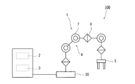
- FIG. 1 is a diagram schematically illustrating a configuration example of a robot system according to an embodiment.
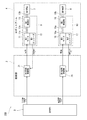
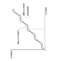
- FIG. 2 is a block diagram illustrating a configuration example of a control system of the robot system in FIG. 1. It is an explanatory view of an angle transmission error.
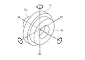
- FIG. 2 is a perspective view illustrating a configuration example of a first joint of the robot system in FIG. 1.
- 3 is a flowchart illustrating an operation example of the robot system in FIG. 1.
- FIG. 2 is a diagram illustrating a measurement result of vibration generated in a robot arm of the robot system in FIG. 1.
- FIG. 2 is a diagram illustrating a measurement result of vibration generated in a robot arm of the robot system in FIG. 1.
- FIG. 1 is a diagram schematically showing a configuration example of the robot system 100.
- the robot system 100 includes a robot 1, a control unit 2, and a command unit 3.
- the robot 1 is an industrial robot of an articulated robot (articulated robot).
- the robot 1 includes a base 30, a robot arm 4, and a hand 5.
- the base 30 is fixedly mounted on, for example, a floor surface, and supports the robot arm 4 and the hand 5.
- the robot system 100 is, for example, a system that performs arc welding. When vibration occurs in the robot arm 4 during arc welding, unevenness occurs in welding marks, so that high trajectory accuracy is required.
- the robot arm 4 has a plurality of joints, and has a base end rotatably connected to the base 30.
- a plurality of joints of the robot arm 4 are arranged in a line from the base end to the tip end.
- One of the plurality of joints of the robot arm 4 constitutes a first joint 7 (for example, a third axis), and another joint (for example, a fourth axis) different from the first joint 7 is a second joint 8. Is composed.
- the first joint 7 and the second joint 8 are joints arranged adjacent to each other via one link without any intervening joint therebetween.
- FIG. 2 is a block diagram schematically showing a configuration example of a control system of the robot system 100 of FIG. 2, illustration of joints other than the first joint 7 and the second joint 8 is omitted.
- each joint of the robot arm 4 has a drive unit for driving the joint.
- Each drive unit has a reduction gear whose output shaft is connected to a corresponding joint (rotating shaft) and an output shaft which is connected to an input shaft of the corresponding reduction gear, and rotates the corresponding joint via the reduction gear. It has a servomotor that is a drive source and an encoder that detects the rotation angle of the output shaft of the servomotor.
- the output shaft of the servomotor is connected to the corresponding joint via the speed reducer. Further, the encoder acquires information on the actual operation of the output shaft of the servomotor. In the present embodiment, the encoder detects the angular position (rotation angle) of the output shaft of the servomotor, and detects the actual rotation angle of the output shaft of the servomotor based on this.
- the servo motor, the speed reducer, and the encoder that drive the first joint 7 are referred to as a first motor 11, a first speed reducer 13, and a first encoder 12, respectively, and these are the first joint drive unit 9 Is composed.
- the servo motor, the speed reducer, and the encoder that drive the second joint 8 are called a second motor 16, a second speed reducer 18, and a second encoder (detection unit) 17, respectively, and these are the second joint drive unit 10 Is composed.
- the rotation angle means an angular position, but is not limited to this. It may be a time differential value of the angular position, that is, an angular velocity or an angular acceleration.
- the speed reducer of the first joint 7, that is, the first speed reducer 13 is, for example, a wave gear device (Harmonic Drive (registered trademark)).
- the speed reducer of the second joint 8 is a speed reducer having a smaller angle transmission error as compared with, for example, a wave gear device.
- the wave gear device includes a circular spline, a flex spline, and a wave generator.
- the circular spline is a rigid internal gear, and is provided, for example, integrally with the housing.
- the flex spline is a flexible external gear, and meshes with the circular spline.
- the flex spline has fewer teeth than the circular spline, and is connected to the output shaft 13b.
- the wave generator is an elliptical cam that contacts the inside of the flex spline, and is connected to the input shaft 13a.
- the wave gear device has characteristics suitable for a reduction gear of a drive mechanism of a robot due to features such as small size and light weight, a high reduction ratio, a high torque capacity, and a non-backlash.
- a reduction gear such as a wave gear device has a theoretical output rotation angle obtained by multiplying an input rotation angle input to the reduction gear by a reduction ratio due to a processing error, and an actual output rotation angle.
- An angle transmission error which is a difference from the rotation angle, occurs.
- This angle transmission error is a periodic change having a predetermined number of waves corresponding to the characteristics of the speed reducer per rotation of the output shaft of the speed reducer as the input shaft rotates, and as shown in FIG. It appears as a micro vibration around the rotation axis R1 of the shaft.
- the micro-vibration also appears as the micro-vibration around the axis R2 orthogonal to the rotation axis R1 and the axis R3 orthogonal to the axis R1 and the axis R2.
- These minute vibrations around the axes R2 and R3 are considered to be caused by bending of members constituting the speed reducer.
- These minute vibrations around the axes R1 to R3 cause the robot arm 4 to vibrate.
- the frequency of the angle transmission error coincides with the natural frequency of the robot arm 4
- resonance sometimes caused the amplitude of the robot arm 4 to gradually increase over time (see FIG. 6A).
- the robot system 100 operates to suppress an increase in amplitude due to the resonance.
- the rotation axis of the second joint 8 extends in a direction inclined with respect to the rotation axis R1 of the first joint 7. More specifically, the rotation axis of the second joint 8 extends in a direction orthogonal to the rotation axis R1 of the first joint 7, and extends, for example, in parallel with the axis R2 shown in FIG.
- the first joint 7 and the second joint 8 are joints in which the relative positional relationship between the axes of the respective joints is in a predetermined fixed relationship. Therefore, among the micro-vibrations generated in the first reduction gear 13, the components around the axis R ⁇ b> 2 cause the second joint 8 to generate micro-vibrations.
- the hand 5 is configured to perform a predetermined operation such as holding of an article, and is attached to a distal end portion of the robot arm 4.
- control unit 2 controls each joint and includes, for example, a microcontroller, a CPU, an arithmetic unit such as a programmable logic device (PLD) such as an ASIC and an FPGA.
- the arithmetic unit may be configured by a single arithmetic unit that performs centralized control, or may be configured by a plurality of arithmetic units that perform distributed control in cooperation with each other.
- the control unit 2 includes a first joint control unit 21 and a second joint control unit 26.
- the first joint control unit 21 and the second joint control unit 26 are functional blocks realized by a predetermined control program being executed by an arithmetic unit (not shown).
- the control unit 2 is configured by an arithmetic unit that is separate from the command unit 3, but may be integrated.
- the first joint control unit 21 determines the first target rotation angle (first operation target) ⁇ t1 with respect to the first motor 11 input from the command unit 3 (upper-level device) and the first motor 11 detected by the first encoder 12. based on the deviation between the actual rotation angle ⁇ 1 of the output shaft 11a, to calculate a first current value i 1 supplied to the first motor 11. Then, to control the rotation angle of the output shaft 11a of the first motor 11 supplies current to the first motor 11 based on the first current value i 1. That is, the first joint control unit 21 controls the deviation between the first target rotation angle ⁇ t1 and the actual rotation angle ⁇ 1 to approach zero, and controls the rotation angle of the output shaft 11a of the first motor 11 to approach the first target rotation angle ⁇ t1. Is performed on the basis of the feedback control of the first motor 11.
- the second joint control unit 26 determines the second target rotation angle (second operation target) ⁇ t2 for the second motor 16 input from the command unit 3 and the output shaft 16a of the second motor 16 detected by the second encoder 17. based on the deviation between the actual rotation angle .theta.2, second current value supplied to the second motor 16 (current command value) to calculate a i 2. Then, to control the rotation angle of the output shaft 16a of the second motor 16 to supply current to the second motor 16 based on the second current value i 2. That is, the second joint control unit 26 controls the deviation between the second target rotation angle ⁇ t2 and the actual rotation angle ⁇ 2 to approach 0, and controls the rotation angle of the output shaft 16a of the second motor 16 to approach the second target rotation angle ⁇ t2. Is performed on the basis of the feedback control of the second motor 16.
- the second joint control unit 26 estimates the vibration of the robot arm 4 caused by the first reduction gear 13, and controls the second current value so as to suppress the vibration.
- i 2 is calculated, correcting a rotational angle of the output shaft 16a of the second motor 16 (described in detail later).
- first joint control unit 21 and the second joint control unit 26 control the first joint 7 and the second joint 8 respectively.
- the vibration component of the vibration in the circumferential direction around the axis of the second joint 8 becomes:
- the second joint 8 is slightly vibrated around its rotation axis. This vibration is a vibration synchronized with the vibration of the first reduction gear 13 of the first joint 7, and the actual rotation of the second joint 8 having the same frequency as the frequency of the fine vibration of the first reduction gear 13 of the first joint 7. It appears as a periodic change in the angle ⁇ 2.
- the phase and relative amplitude of the minute vibration caused by the first reduction gear 13 on the basis of the actual rotation angle ⁇ 2 of the output shaft 16a of the second motor 16 to the second current value i 2 or the second encoder 17 detects It is possible to estimate the size.
- the second articulation control 26 estimates the phase and relative magnitude of the amplitude of the minute vibration based on the second current value i 2.
- the command unit 3 is a higher-level device of the first joint control unit 21 and the second joint control unit 26, and generates and outputs a position command for each joint, that is, a target rotation angle of each joint, based on an operation program.
- the target rotation angle of each joint includes a first target rotation angle ⁇ t1 for the first motor 11 and a second target rotation angle ⁇ t2 for the second motor 16.
- the output target rotation angle is input to a joint control unit including the first joint control unit 21 and the second joint control unit 26.
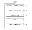
- FIG. 5 is a flowchart showing an operation example of the robot system 100.
- the second joint control unit 26 calculates the frequency ⁇ related to the angle transmission error of the first reduction gear 13.
- the second joint control unit 26 performs a first command based on the speed command value for the first motor 11 acquired from the first joint control unit 21 and the number of waves of the angle transmission error per one rotation of the output shaft of the first motor 11.
- the frequency ⁇ related to the angle transmission error of the speed reducer 13 is calculated (Step S10).
- the frequency ⁇ is a value that changes every moment due to a change in the angular velocity of the first motor 11.
- the robot system 100 is a system that operates so as to suppress the micro vibration based on the angle transmission error and the increase in the amplitude due to the resonance of the robot arm 4.
- the frequency of the angle transmission error and the robot arm 4 will be described.
- the frequency ⁇ is used as a value that matches the natural frequency of.
- the second joint control unit 26 while the periodic variation of the angle transmission error of the first reduction gear 13 has passed one period 2 [pi / omega, the first reduction device included in the second current value i 2 13
- the amplitude and phase of the component u (t) synchronized with the frequency ⁇ of the angle transmission error are calculated by Fourier expansion (step S20).
- the second joint control unit 26 calculates the vibration ⁇ 2 n (t) of the second joint 8 in the n-th cycle using the calculated values B and ⁇ according to the following equation (6).
- the vibration ⁇ 2 n (t) generated around the rotation axis of the second joint 8 is estimated (step S30).
- the second joint control unit 26 calculates the operation compensation amount .theta.m n + 1 in the next (n + 1) th cycle as shown in formula (7) (step S40).
- the motion correction amount ⁇ m n + 1 is a value calculated based on the amplitude An and the phase difference D defined to suppress the vibration ⁇ 2 n (t).
- the amplitude A n of motion correction amount ⁇ m n + 1 (t) is allowed to cancel the vibration generated in the second joint 8, instead of the value that gives greater control input so as to eliminate the vibration, the amplitude of the vibration by the resonance
- This value is small enough to suppress the increase, and is, for example, a value equal to or less than 1/10 of the amplitude of the vibration generated in the second joint 8.
- the second joint control unit 26 calculates the second target rotation angle ⁇ t2 for the second motor 16 input from the command unit 3 and the actual rotation angle of the output shaft 16a of the second motor 16 detected by the second encoder 17. based on the deviation between .theta.2, when calculating the second current value i 2 supplied to the second motor 16 in the (n + 1) th cycle, and calculates the operation compensation amount .theta.m n + 1 second current value i 2 in consideration of. That is, the second joint control unit 26 corrects the position command value by adding the operation correction amount ⁇ mn + 1 to the position command value in the (n + 1) th cycle. The second joint controller 26 calculates a second current value i 2 on the basis of the corrected position command value. The second joint controller 26 controls the rotation angle of the output shaft 16a of the second motor 16 to supply current to the second motor 16 based on the second current value i 2 (step S50).
- step S10 the processing performed in the n-th cycle is also performed in the (n + 1) -th cycle. As described above, the second joint control unit 26 repeatedly executes steps S10 to S50.
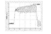
- FIG. 6A is a graph showing a measurement result of the vibration generated in the robot arm 4 of the robot system 100, and is a graph showing the measurement result when the vibration suppression control is not performed.
- FIG. 6B is a graph illustrating a measurement result of the vibration generated in the robot arm 4 of the robot system 100, and is a graph illustrating the measurement result when the vibration suppression control is performed.
- the vertical axis indicates the angular velocity of the vibration
- the horizontal axis indicates the time.
- FIG. 6A when the control input for suppressing the vibration was not applied, while the vibration increased with time, the control input for suppressing the vibration was applied as shown in FIG. 6B. In this case, it can be seen that the vibration is significantly suppressed to a constant amplitude.
- the robot system 100 of the present invention includes the robot arm 4 having a plurality of joints including the first joint 7 and the second joint 8 and the first arm 7 in which the output shaft 13 b is connected to the first joint 7.
- a first joint drive unit having a speed reducer 13 and an output shaft 11a connected to an input shaft 13a of the first speed reducer 13 and having a first motor 11 for rotating the first joint 7 via the first speed reducer 13 9, a first joint control unit 21 for controlling the operation of the output shaft 11a of the first motor 11 based on a first operation target for the first motor 11 input from the host device, and the output shaft 16a
- a second joint drive unit 10 having a second motor 16 for rotating the second joint 8, a detection unit 17 for acquiring information on the actual operation of the output shaft 16 a of the second motor 16,
- the second motor 16 Calculating a target motion and the second current value i 2 supplied to the second motor 16 based on the deviation between the actual operation ⁇ 1 of the output shaft 16a of the second motor 16, and the second motor 16 based on
- the second joint control unit 26 supplies a second current value i 2 (or the second motor 16
- the rotation of the second joint 8 is based on the same frequency component as the frequency of the periodic change in the angular position, angular velocity, or torque of the output shaft 13b of the first reduction gear 13 included in the time change of the output shaft 16a (actual operation of the output shaft 16a).
- the vibration of the robot arm 4 around the moving axis is estimated, and the operation of the output shaft 16a of the second motor 16 is corrected so as to suppress the estimated vibration of the robot arm 4.
- the vibration of the robot arm 4 caused by the angle transmission error of the first reduction gear 13 can be suppressed, and the trajectory accuracy of the hand 5 can be improved.
- the trajectory accuracy can be improved with a simple configuration, and the manufacturing cost can be reduced.
- the periodic change in the angular position, angular velocity, or torque of the output shaft 13b of the first reduction gear 13 may be a change due to the characteristics of the first joint drive unit 9.
- the vibration of the robot arm 4 based on the periodic change in the angular position, angular velocity, or torque of the output shaft 13b of the first reduction gear 13 due to the characteristics of the first joint drive unit 9 is appropriately suppressed. be able to.
- the frequency of the periodic change of the angular position, angular velocity or torque of the output shaft 13b of the first reduction gear 13 may be the frequency of the angle transmission error of the first reduction gear 13.
- the vibration of the robot arm 4 based on the angle transmission error of the first reduction gear 13 can be appropriately suppressed.
- the vibration of the robot arm 4 about the rotation axis of the second joint 8 estimated by the second joint control unit 26 may be a vibration caused by an angle transmission error of the first speed reducer 13.
- a robot system capable of suppressing vibration of the robot arm 4 due to an angle transmission error of the first reduction gear 13 can be appropriately configured.
- the second joint control unit 26 controls the output shaft 13b of the first reduction gear 13 of the frequency components included in the time change of the second current value i 2 (or the actual operation of the output shaft 16a of the second motor 16).
- the amplitude of the same frequency component as the frequency of the periodic change in the angular position, the angular velocity, or the torque may be calculated, and the vibration of the robot arm 4 around the rotation axis of the second joint 8 may be estimated based on the amplitude.
- the rotation axis of the second joint 8 may be inclined with respect to the rotation axis of the output shaft 13b of the first reduction gear 13.
- vibration around a rotation axis different from the rotation axis of the output shaft 13b of the first reduction gear 13 can be suppressed. That is, it is possible to suppress vibration other than vibration in the circumferential direction about the rotation axis R1 of the output shaft 13b of the first reduction gear 13, that is, vibration in the circumferential direction about the axes R2 and R3. it can.
- the operation correction amount ⁇ mn + 1 is a value represented by the equation (7), but is not limited thereto.
- a value represented by the following equation (8) may be used.
- the rotation axis of the second joint 8 is an axis extending in a direction orthogonal to the rotation axis of the first joint 7.
- the present invention is not limited to this. May have an arbitrary relative posture with respect to the rotation axis of.
- the rotation axis of the second joint 8 may extend parallel to the rotation axis of the first joint 7, and in this case, the robot system 100 compensates for the angle transmission error of the first reduction gear 13. can do.
- the second joint control unit 26 periodically controls the angular position of the angle transmission error of the first speed reducer 13 so as to suppress the vibration caused by the angle transmission error of the first speed reducer 13.
- the operation correction amount is calculated based on the frequency of the change, the present invention is not limited to this.
- the second joint control unit 26 uses the frequency of the periodic change in the angular position, angular velocity, or torque of the output shaft 13b of the first reduction gear 13 due to the characteristics of the first joint drive unit 9 other than the angle transmission error.
- the motion correction amount may be calculated.
- the motion correction amount is calculated based on the frequency of the periodic change in the torque of the output shaft 13b of the first reduction gear 13 caused by the torque ripple of the first joint driving unit 9. You may.
Landscapes
- Engineering & Computer Science (AREA)
- Power Engineering (AREA)
- Robotics (AREA)
- Mechanical Engineering (AREA)
- Manipulator (AREA)
Abstract
La présente invention comprend : un bras robotisé (4) ayant une pluralité d'articulations comprenant une première articulation (7) et une seconde articulation (8) ; une première unité d'entraînement d'articulation (9) ayant un premier réducteur de vitesse (13) et un premier moteur (11) qui met en rotation la première articulation (7) par l'intermédiaire du premier réducteur de vitesse (13) ; une première unité de commande d'articulation (21) qui commande le mouvement d'un arbre de sortie (11a) du premier moteur (11) ; une seconde unité d'entraînement d'articulation (10) ayant un second moteur (16) qui met en rotation la seconde articulation (8) ; une unité de détection (17) qui acquiert des informations concernant le mouvement réel d'un arbre de sortie (16a) du second moteur (16) ; et une seconde unité de commande d'articulation (26) qui commande le mouvement de l'arbre de sortie (16a) du second moteur (16). La seconde unité de commande d'articulation (26) estime une vibration du bras robotisé (4) autour de l'axe de rotation de la seconde articulation (8) sur la base d'une composante de fréquence identique à celle de la fréquence d'un changement périodique de la position angulaire, de la vitesse angulaire ou du couple d'un arbre de sortie (13b) du premier réducteur de vitesse (13) inclus dans un changement temporel d'une seconde valeur de courant (i2) ou du mouvement réel de l'arbre de sortie (16a) du second moteur (16), et corrige le mouvement de l'arbre de sortie (16a) du second moteur (16) de façon à supprimer la vibration estimée du bras robotisé (4).
Priority Applications (1)
| Application Number | Priority Date | Filing Date | Title |
|---|---|---|---|
| CN201980045065.9A CN112584989B (zh) | 2018-07-06 | 2019-07-05 | 机器人系统和机器人系统的控制方法 |
Applications Claiming Priority (4)
| Application Number | Priority Date | Filing Date | Title |
|---|---|---|---|
| JP2018129328 | 2018-07-06 | ||
| JP2018-129328 | 2018-07-06 | ||
| JP2018-163554 | 2018-08-31 | ||
| JP2018163554A JP7121599B2 (ja) | 2018-07-06 | 2018-08-31 | ロボットシステム及びロボットシステムの制御方法 |
Publications (1)
| Publication Number | Publication Date |
|---|---|
| WO2020009237A1 true WO2020009237A1 (fr) | 2020-01-09 |
Family
ID=69060454
Family Applications (1)
| Application Number | Title | Priority Date | Filing Date |
|---|---|---|---|
| PCT/JP2019/026891 Ceased WO2020009237A1 (fr) | 2018-07-06 | 2019-07-05 | Système robotisé et procédé de commande de système robotisé |
Country Status (1)
| Country | Link |
|---|---|
| WO (1) | WO2020009237A1 (fr) |
Citations (5)
| Publication number | Priority date | Publication date | Assignee | Title |
|---|---|---|---|---|
| JPH04310112A (ja) * | 1991-04-09 | 1992-11-02 | Matsushita Electric Ind Co Ltd | ロボットアームのサーボ制御装置 |
| JP2010149203A (ja) * | 2008-12-24 | 2010-07-08 | Yaskawa Electric Corp | ロボット制御装置およびロボットシステム |
| JP2011224662A (ja) * | 2010-04-15 | 2011-11-10 | Yaskawa Electric Corp | ロボット制御装置の補正パラメータ同定装置 |
| JP2014136260A (ja) * | 2013-01-15 | 2014-07-28 | Daihen Corp | 制御装置 |
| WO2018235812A1 (fr) * | 2017-06-21 | 2018-12-27 | 川崎重工業株式会社 | Système de robot et procédé de commande d'un système de robot |
-
2019
- 2019-07-05 WO PCT/JP2019/026891 patent/WO2020009237A1/fr not_active Ceased
Patent Citations (5)
| Publication number | Priority date | Publication date | Assignee | Title |
|---|---|---|---|---|
| JPH04310112A (ja) * | 1991-04-09 | 1992-11-02 | Matsushita Electric Ind Co Ltd | ロボットアームのサーボ制御装置 |
| JP2010149203A (ja) * | 2008-12-24 | 2010-07-08 | Yaskawa Electric Corp | ロボット制御装置およびロボットシステム |
| JP2011224662A (ja) * | 2010-04-15 | 2011-11-10 | Yaskawa Electric Corp | ロボット制御装置の補正パラメータ同定装置 |
| JP2014136260A (ja) * | 2013-01-15 | 2014-07-28 | Daihen Corp | 制御装置 |
| WO2018235812A1 (fr) * | 2017-06-21 | 2018-12-27 | 川崎重工業株式会社 | Système de robot et procédé de commande d'un système de robot |
Similar Documents
| Publication | Publication Date | Title |
|---|---|---|
| US11559891B2 (en) | Robot system and method for controlling robot system | |
| JP7117827B2 (ja) | モータ制御システム、モータ制御システムの制御方法、及びロボットシステム | |
| JP6374274B2 (ja) | 制御装置及び減速機システム | |
| CN104736303B (zh) | 多关节机器人的摆动控制装置 | |
| CN107379016A (zh) | 可动部的振动测定方法、机器人的振动测定方法以及控制装置 | |
| JP6860417B2 (ja) | 減速機角度伝達誤差同定システム及び減速機角度伝達誤差同定方法 | |
| CN104349873A (zh) | 多关节机器人的弹性变形补偿控制装置以及控制方法 | |
| WO2013031465A1 (fr) | Procédé de commande et dispositif de commande | |
| JP5277946B2 (ja) | ロボット制御装置およびロボットシステム | |
| JP2016078149A (ja) | ロボット装置の制御方法及びロボット装置、プログラム及び記録媒体 | |
| JP7121599B2 (ja) | ロボットシステム及びロボットシステムの制御方法 | |
| WO2020009237A1 (fr) | Système robotisé et procédé de commande de système robotisé | |
| JP2018202589A (ja) | 制御装置、ロボット、およびロボットシステム | |
| JP6814441B2 (ja) | 駆動機械の学習制御装置及び学習制御方法 | |
| JP6252272B2 (ja) | 垂直多関節型ロボットの位置誤差抑制方法 | |
| JP6391489B2 (ja) | モータ制御装置 | |
| JP5262880B2 (ja) | ロボット制御装置 | |
| JP2024155507A (ja) | ロボット | |
| JP2019055456A (ja) | ロボットの制御装置 |
Legal Events
| Date | Code | Title | Description |
|---|---|---|---|
| 121 | Ep: the epo has been informed by wipo that ep was designated in this application |
Ref document number: 19831368 Country of ref document: EP Kind code of ref document: A1 |
|
| NENP | Non-entry into the national phase |
Ref country code: DE |
|
| 122 | Ep: pct application non-entry in european phase |
Ref document number: 19831368 Country of ref document: EP Kind code of ref document: A1 |