WO2020009237A1 - ロボットシステム及びロボットシステムの制御方法 - Google Patents
ロボットシステム及びロボットシステムの制御方法 Download PDFInfo
- Publication number
- WO2020009237A1 WO2020009237A1 PCT/JP2019/026891 JP2019026891W WO2020009237A1 WO 2020009237 A1 WO2020009237 A1 WO 2020009237A1 JP 2019026891 W JP2019026891 W JP 2019026891W WO 2020009237 A1 WO2020009237 A1 WO 2020009237A1
- Authority
- WO
- WIPO (PCT)
- Prior art keywords
- joint
- motor
- output shaft
- reduction gear
- vibration
- Prior art date
- Legal status (The legal status is an assumption and is not a legal conclusion. Google has not performed a legal analysis and makes no representation as to the accuracy of the status listed.)
- Ceased
Links
Images

Classifications
-
- B—PERFORMING OPERATIONS; TRANSPORTING
- B25—HAND TOOLS; PORTABLE POWER-DRIVEN TOOLS; MANIPULATORS
- B25J—MANIPULATORS; CHAMBERS PROVIDED WITH MANIPULATION DEVICES
- B25J13/00—Controls for manipulators
-
- H—ELECTRICITY
- H02—GENERATION; CONVERSION OR DISTRIBUTION OF ELECTRIC POWER
- H02P—CONTROL OR REGULATION OF ELECTRIC MOTORS, ELECTRIC GENERATORS OR DYNAMO-ELECTRIC CONVERTERS; CONTROLLING TRANSFORMERS, REACTORS OR CHOKE COILS
- H02P5/00—Arrangements specially adapted for regulating or controlling the speed or torque of two or more electric motors
- H02P5/46—Arrangements specially adapted for regulating or controlling the speed or torque of two or more electric motors for speed regulation of two or more dynamo-electric motors in relation to one another
-
- H—ELECTRICITY
- H02—GENERATION; CONVERSION OR DISTRIBUTION OF ELECTRIC POWER
- H02P—CONTROL OR REGULATION OF ELECTRIC MOTORS, ELECTRIC GENERATORS OR DYNAMO-ELECTRIC CONVERTERS; CONTROLLING TRANSFORMERS, REACTORS OR CHOKE COILS
- H02P6/00—Arrangements for controlling synchronous motors or other dynamo-electric motors using electronic commutation dependent on the rotor position; Electronic commutators therefor
- H02P6/28—Arrangements for controlling current
Definitions
- the present invention relates to a robot system and a control method for the robot system.
- a control device of a motor drive device disclosed in Patent Document 1 is known.
- the control device includes a thrust control unit that generates a motor position command value based on the input thrust command value, and a motor control unit that generates a current value based on the motor position command value.
- the motor position detected by the motor encoder is fed back, and the thrust control unit feeds back the thrust detected by the thrust meter.
- the vibration phenomenon of the speed reducer is suppressed by the feedback of the motor control unit, and the transmission error is suppressed by the feedback of the thrust control unit, thereby enabling quick and precise movement control of the arm.
- control device of the motor drive device described in Patent Document 1 needs to be provided with a thrust meter, and has a problem that the configuration is complicated and the manufacturing cost is high.
- a robot system includes a robot arm having a plurality of joints including a first joint and a second joint, and a first deceleration having an output shaft connected to the first joint.
- a first joint drive unit having an output shaft connected to an input shaft of the first speed reducer, and a first motor for rotating the first joint via the first speed reducer;
- a first joint control unit that controls the operation of the output shaft of the first motor based on the input first operation target for the first motor; an output shaft connected to the second joint;
- a second joint drive unit having a second motor for rotating the motor, a detection unit for acquiring information on the actual operation of the output shaft of the second motor, and a second motor for the second motor input from the host device.
- Operating target and the output of the second motor Calculating a second current value to be supplied to the second motor based on a deviation from the actual operation of the second motor, and supplying a current to the second motor based on the second current value to operate the output shaft of the second motor.
- a second joint control unit that controls a time change of the second current value or an actual operation of the output shaft of the second motor. Based on the same frequency component as the angular position of the output shaft, the frequency of the angular velocity or the frequency of the periodic change in torque, the vibration of the robot arm around the rotation axis of the second joint is estimated, and the estimated robot arm The operation of the output shaft of the second motor is corrected so as to suppress vibration.
- the vibration of the robot arm caused by the angle transmission error of the first reduction gear can be suppressed, and the trajectory accuracy can be improved.
- the trajectory accuracy can be improved with a simple configuration, and the manufacturing cost can be reduced.
- This invention can suppress the vibration of a robot arm resulting from the angle transmission error of a 1st reduction gear, can improve trajectory accuracy, can improve trajectory accuracy with a simple structure, and can also reduce manufacturing cost. This has the effect of being cheap.
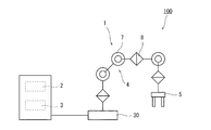
- FIG. 1 is a diagram schematically illustrating a configuration example of a robot system according to an embodiment.
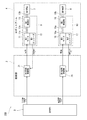
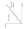
- FIG. 2 is a block diagram illustrating a configuration example of a control system of the robot system in FIG. 1. It is an explanatory view of an angle transmission error.
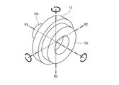
- FIG. 2 is a perspective view illustrating a configuration example of a first joint of the robot system in FIG. 1.
- 3 is a flowchart illustrating an operation example of the robot system in FIG. 1.
- FIG. 2 is a diagram illustrating a measurement result of vibration generated in a robot arm of the robot system in FIG. 1.
- FIG. 2 is a diagram illustrating a measurement result of vibration generated in a robot arm of the robot system in FIG. 1.
- FIG. 1 is a diagram schematically showing a configuration example of the robot system 100.
- the robot system 100 includes a robot 1, a control unit 2, and a command unit 3.
- the robot 1 is an industrial robot of an articulated robot (articulated robot).
- the robot 1 includes a base 30, a robot arm 4, and a hand 5.
- the base 30 is fixedly mounted on, for example, a floor surface, and supports the robot arm 4 and the hand 5.
- the robot system 100 is, for example, a system that performs arc welding. When vibration occurs in the robot arm 4 during arc welding, unevenness occurs in welding marks, so that high trajectory accuracy is required.
- the robot arm 4 has a plurality of joints, and has a base end rotatably connected to the base 30.
- a plurality of joints of the robot arm 4 are arranged in a line from the base end to the tip end.
- One of the plurality of joints of the robot arm 4 constitutes a first joint 7 (for example, a third axis), and another joint (for example, a fourth axis) different from the first joint 7 is a second joint 8. Is composed.
- the first joint 7 and the second joint 8 are joints arranged adjacent to each other via one link without any intervening joint therebetween.
- FIG. 2 is a block diagram schematically showing a configuration example of a control system of the robot system 100 of FIG. 2, illustration of joints other than the first joint 7 and the second joint 8 is omitted.
- each joint of the robot arm 4 has a drive unit for driving the joint.
- Each drive unit has a reduction gear whose output shaft is connected to a corresponding joint (rotating shaft) and an output shaft which is connected to an input shaft of the corresponding reduction gear, and rotates the corresponding joint via the reduction gear. It has a servomotor that is a drive source and an encoder that detects the rotation angle of the output shaft of the servomotor.
- the output shaft of the servomotor is connected to the corresponding joint via the speed reducer. Further, the encoder acquires information on the actual operation of the output shaft of the servomotor. In the present embodiment, the encoder detects the angular position (rotation angle) of the output shaft of the servomotor, and detects the actual rotation angle of the output shaft of the servomotor based on this.
- the servo motor, the speed reducer, and the encoder that drive the first joint 7 are referred to as a first motor 11, a first speed reducer 13, and a first encoder 12, respectively, and these are the first joint drive unit 9 Is composed.
- the servo motor, the speed reducer, and the encoder that drive the second joint 8 are called a second motor 16, a second speed reducer 18, and a second encoder (detection unit) 17, respectively, and these are the second joint drive unit 10 Is composed.
- the rotation angle means an angular position, but is not limited to this. It may be a time differential value of the angular position, that is, an angular velocity or an angular acceleration.
- the speed reducer of the first joint 7, that is, the first speed reducer 13 is, for example, a wave gear device (Harmonic Drive (registered trademark)).
- the speed reducer of the second joint 8 is a speed reducer having a smaller angle transmission error as compared with, for example, a wave gear device.
- the wave gear device includes a circular spline, a flex spline, and a wave generator.
- the circular spline is a rigid internal gear, and is provided, for example, integrally with the housing.
- the flex spline is a flexible external gear, and meshes with the circular spline.
- the flex spline has fewer teeth than the circular spline, and is connected to the output shaft 13b.
- the wave generator is an elliptical cam that contacts the inside of the flex spline, and is connected to the input shaft 13a.
- the wave gear device has characteristics suitable for a reduction gear of a drive mechanism of a robot due to features such as small size and light weight, a high reduction ratio, a high torque capacity, and a non-backlash.
- a reduction gear such as a wave gear device has a theoretical output rotation angle obtained by multiplying an input rotation angle input to the reduction gear by a reduction ratio due to a processing error, and an actual output rotation angle.
- An angle transmission error which is a difference from the rotation angle, occurs.
- This angle transmission error is a periodic change having a predetermined number of waves corresponding to the characteristics of the speed reducer per rotation of the output shaft of the speed reducer as the input shaft rotates, and as shown in FIG. It appears as a micro vibration around the rotation axis R1 of the shaft.
- the micro-vibration also appears as the micro-vibration around the axis R2 orthogonal to the rotation axis R1 and the axis R3 orthogonal to the axis R1 and the axis R2.
- These minute vibrations around the axes R2 and R3 are considered to be caused by bending of members constituting the speed reducer.
- These minute vibrations around the axes R1 to R3 cause the robot arm 4 to vibrate.
- the frequency of the angle transmission error coincides with the natural frequency of the robot arm 4
- resonance sometimes caused the amplitude of the robot arm 4 to gradually increase over time (see FIG. 6A).
- the robot system 100 operates to suppress an increase in amplitude due to the resonance.
- the rotation axis of the second joint 8 extends in a direction inclined with respect to the rotation axis R1 of the first joint 7. More specifically, the rotation axis of the second joint 8 extends in a direction orthogonal to the rotation axis R1 of the first joint 7, and extends, for example, in parallel with the axis R2 shown in FIG.
- the first joint 7 and the second joint 8 are joints in which the relative positional relationship between the axes of the respective joints is in a predetermined fixed relationship. Therefore, among the micro-vibrations generated in the first reduction gear 13, the components around the axis R ⁇ b> 2 cause the second joint 8 to generate micro-vibrations.
- the hand 5 is configured to perform a predetermined operation such as holding of an article, and is attached to a distal end portion of the robot arm 4.
- control unit 2 controls each joint and includes, for example, a microcontroller, a CPU, an arithmetic unit such as a programmable logic device (PLD) such as an ASIC and an FPGA.
- the arithmetic unit may be configured by a single arithmetic unit that performs centralized control, or may be configured by a plurality of arithmetic units that perform distributed control in cooperation with each other.
- the control unit 2 includes a first joint control unit 21 and a second joint control unit 26.
- the first joint control unit 21 and the second joint control unit 26 are functional blocks realized by a predetermined control program being executed by an arithmetic unit (not shown).
- the control unit 2 is configured by an arithmetic unit that is separate from the command unit 3, but may be integrated.
- the first joint control unit 21 determines the first target rotation angle (first operation target) ⁇ t1 with respect to the first motor 11 input from the command unit 3 (upper-level device) and the first motor 11 detected by the first encoder 12. based on the deviation between the actual rotation angle ⁇ 1 of the output shaft 11a, to calculate a first current value i 1 supplied to the first motor 11. Then, to control the rotation angle of the output shaft 11a of the first motor 11 supplies current to the first motor 11 based on the first current value i 1. That is, the first joint control unit 21 controls the deviation between the first target rotation angle ⁇ t1 and the actual rotation angle ⁇ 1 to approach zero, and controls the rotation angle of the output shaft 11a of the first motor 11 to approach the first target rotation angle ⁇ t1. Is performed on the basis of the feedback control of the first motor 11.
- the second joint control unit 26 determines the second target rotation angle (second operation target) ⁇ t2 for the second motor 16 input from the command unit 3 and the output shaft 16a of the second motor 16 detected by the second encoder 17. based on the deviation between the actual rotation angle .theta.2, second current value supplied to the second motor 16 (current command value) to calculate a i 2. Then, to control the rotation angle of the output shaft 16a of the second motor 16 to supply current to the second motor 16 based on the second current value i 2. That is, the second joint control unit 26 controls the deviation between the second target rotation angle ⁇ t2 and the actual rotation angle ⁇ 2 to approach 0, and controls the rotation angle of the output shaft 16a of the second motor 16 to approach the second target rotation angle ⁇ t2. Is performed on the basis of the feedback control of the second motor 16.
- the second joint control unit 26 estimates the vibration of the robot arm 4 caused by the first reduction gear 13, and controls the second current value so as to suppress the vibration.
- i 2 is calculated, correcting a rotational angle of the output shaft 16a of the second motor 16 (described in detail later).
- first joint control unit 21 and the second joint control unit 26 control the first joint 7 and the second joint 8 respectively.
- the vibration component of the vibration in the circumferential direction around the axis of the second joint 8 becomes:
- the second joint 8 is slightly vibrated around its rotation axis. This vibration is a vibration synchronized with the vibration of the first reduction gear 13 of the first joint 7, and the actual rotation of the second joint 8 having the same frequency as the frequency of the fine vibration of the first reduction gear 13 of the first joint 7. It appears as a periodic change in the angle ⁇ 2.
- the phase and relative amplitude of the minute vibration caused by the first reduction gear 13 on the basis of the actual rotation angle ⁇ 2 of the output shaft 16a of the second motor 16 to the second current value i 2 or the second encoder 17 detects It is possible to estimate the size.
- the second articulation control 26 estimates the phase and relative magnitude of the amplitude of the minute vibration based on the second current value i 2.
- the command unit 3 is a higher-level device of the first joint control unit 21 and the second joint control unit 26, and generates and outputs a position command for each joint, that is, a target rotation angle of each joint, based on an operation program.
- the target rotation angle of each joint includes a first target rotation angle ⁇ t1 for the first motor 11 and a second target rotation angle ⁇ t2 for the second motor 16.
- the output target rotation angle is input to a joint control unit including the first joint control unit 21 and the second joint control unit 26.
- FIG. 5 is a flowchart showing an operation example of the robot system 100.
- the second joint control unit 26 calculates the frequency ⁇ related to the angle transmission error of the first reduction gear 13.
- the second joint control unit 26 performs a first command based on the speed command value for the first motor 11 acquired from the first joint control unit 21 and the number of waves of the angle transmission error per one rotation of the output shaft of the first motor 11.
- the frequency ⁇ related to the angle transmission error of the speed reducer 13 is calculated (Step S10).
- the frequency ⁇ is a value that changes every moment due to a change in the angular velocity of the first motor 11.
- the robot system 100 is a system that operates so as to suppress the micro vibration based on the angle transmission error and the increase in the amplitude due to the resonance of the robot arm 4.
- the frequency of the angle transmission error and the robot arm 4 will be described.
- the frequency ⁇ is used as a value that matches the natural frequency of.
- the second joint control unit 26 while the periodic variation of the angle transmission error of the first reduction gear 13 has passed one period 2 [pi / omega, the first reduction device included in the second current value i 2 13
- the amplitude and phase of the component u (t) synchronized with the frequency ⁇ of the angle transmission error are calculated by Fourier expansion (step S20).
- the second joint control unit 26 calculates the vibration ⁇ 2 n (t) of the second joint 8 in the n-th cycle using the calculated values B and ⁇ according to the following equation (6).
- the vibration ⁇ 2 n (t) generated around the rotation axis of the second joint 8 is estimated (step S30).
- the second joint control unit 26 calculates the operation compensation amount .theta.m n + 1 in the next (n + 1) th cycle as shown in formula (7) (step S40).
- the motion correction amount ⁇ m n + 1 is a value calculated based on the amplitude An and the phase difference D defined to suppress the vibration ⁇ 2 n (t).
- the amplitude A n of motion correction amount ⁇ m n + 1 (t) is allowed to cancel the vibration generated in the second joint 8, instead of the value that gives greater control input so as to eliminate the vibration, the amplitude of the vibration by the resonance
- This value is small enough to suppress the increase, and is, for example, a value equal to or less than 1/10 of the amplitude of the vibration generated in the second joint 8.
- the second joint control unit 26 calculates the second target rotation angle ⁇ t2 for the second motor 16 input from the command unit 3 and the actual rotation angle of the output shaft 16a of the second motor 16 detected by the second encoder 17. based on the deviation between .theta.2, when calculating the second current value i 2 supplied to the second motor 16 in the (n + 1) th cycle, and calculates the operation compensation amount .theta.m n + 1 second current value i 2 in consideration of. That is, the second joint control unit 26 corrects the position command value by adding the operation correction amount ⁇ mn + 1 to the position command value in the (n + 1) th cycle. The second joint controller 26 calculates a second current value i 2 on the basis of the corrected position command value. The second joint controller 26 controls the rotation angle of the output shaft 16a of the second motor 16 to supply current to the second motor 16 based on the second current value i 2 (step S50).
- step S10 the processing performed in the n-th cycle is also performed in the (n + 1) -th cycle. As described above, the second joint control unit 26 repeatedly executes steps S10 to S50.
- FIG. 6A is a graph showing a measurement result of the vibration generated in the robot arm 4 of the robot system 100, and is a graph showing the measurement result when the vibration suppression control is not performed.
- FIG. 6B is a graph illustrating a measurement result of the vibration generated in the robot arm 4 of the robot system 100, and is a graph illustrating the measurement result when the vibration suppression control is performed.
- the vertical axis indicates the angular velocity of the vibration
- the horizontal axis indicates the time.
- FIG. 6A when the control input for suppressing the vibration was not applied, while the vibration increased with time, the control input for suppressing the vibration was applied as shown in FIG. 6B. In this case, it can be seen that the vibration is significantly suppressed to a constant amplitude.
- the robot system 100 of the present invention includes the robot arm 4 having a plurality of joints including the first joint 7 and the second joint 8 and the first arm 7 in which the output shaft 13 b is connected to the first joint 7.
- a first joint drive unit having a speed reducer 13 and an output shaft 11a connected to an input shaft 13a of the first speed reducer 13 and having a first motor 11 for rotating the first joint 7 via the first speed reducer 13 9, a first joint control unit 21 for controlling the operation of the output shaft 11a of the first motor 11 based on a first operation target for the first motor 11 input from the host device, and the output shaft 16a
- a second joint drive unit 10 having a second motor 16 for rotating the second joint 8, a detection unit 17 for acquiring information on the actual operation of the output shaft 16 a of the second motor 16,
- the second motor 16 Calculating a target motion and the second current value i 2 supplied to the second motor 16 based on the deviation between the actual operation ⁇ 1 of the output shaft 16a of the second motor 16, and the second motor 16 based on
- the second joint control unit 26 supplies a second current value i 2 (or the second motor 16
- the rotation of the second joint 8 is based on the same frequency component as the frequency of the periodic change in the angular position, angular velocity, or torque of the output shaft 13b of the first reduction gear 13 included in the time change of the output shaft 16a (actual operation of the output shaft 16a).
- the vibration of the robot arm 4 around the moving axis is estimated, and the operation of the output shaft 16a of the second motor 16 is corrected so as to suppress the estimated vibration of the robot arm 4.
- the vibration of the robot arm 4 caused by the angle transmission error of the first reduction gear 13 can be suppressed, and the trajectory accuracy of the hand 5 can be improved.
- the trajectory accuracy can be improved with a simple configuration, and the manufacturing cost can be reduced.
- the periodic change in the angular position, angular velocity, or torque of the output shaft 13b of the first reduction gear 13 may be a change due to the characteristics of the first joint drive unit 9.
- the vibration of the robot arm 4 based on the periodic change in the angular position, angular velocity, or torque of the output shaft 13b of the first reduction gear 13 due to the characteristics of the first joint drive unit 9 is appropriately suppressed. be able to.
- the frequency of the periodic change of the angular position, angular velocity or torque of the output shaft 13b of the first reduction gear 13 may be the frequency of the angle transmission error of the first reduction gear 13.
- the vibration of the robot arm 4 based on the angle transmission error of the first reduction gear 13 can be appropriately suppressed.
- the vibration of the robot arm 4 about the rotation axis of the second joint 8 estimated by the second joint control unit 26 may be a vibration caused by an angle transmission error of the first speed reducer 13.
- a robot system capable of suppressing vibration of the robot arm 4 due to an angle transmission error of the first reduction gear 13 can be appropriately configured.
- the second joint control unit 26 controls the output shaft 13b of the first reduction gear 13 of the frequency components included in the time change of the second current value i 2 (or the actual operation of the output shaft 16a of the second motor 16).
- the amplitude of the same frequency component as the frequency of the periodic change in the angular position, the angular velocity, or the torque may be calculated, and the vibration of the robot arm 4 around the rotation axis of the second joint 8 may be estimated based on the amplitude.
- the rotation axis of the second joint 8 may be inclined with respect to the rotation axis of the output shaft 13b of the first reduction gear 13.
- vibration around a rotation axis different from the rotation axis of the output shaft 13b of the first reduction gear 13 can be suppressed. That is, it is possible to suppress vibration other than vibration in the circumferential direction about the rotation axis R1 of the output shaft 13b of the first reduction gear 13, that is, vibration in the circumferential direction about the axes R2 and R3. it can.
- the operation correction amount ⁇ mn + 1 is a value represented by the equation (7), but is not limited thereto.
- a value represented by the following equation (8) may be used.
- the rotation axis of the second joint 8 is an axis extending in a direction orthogonal to the rotation axis of the first joint 7.
- the present invention is not limited to this. May have an arbitrary relative posture with respect to the rotation axis of.
- the rotation axis of the second joint 8 may extend parallel to the rotation axis of the first joint 7, and in this case, the robot system 100 compensates for the angle transmission error of the first reduction gear 13. can do.
- the second joint control unit 26 periodically controls the angular position of the angle transmission error of the first speed reducer 13 so as to suppress the vibration caused by the angle transmission error of the first speed reducer 13.
- the operation correction amount is calculated based on the frequency of the change, the present invention is not limited to this.
- the second joint control unit 26 uses the frequency of the periodic change in the angular position, angular velocity, or torque of the output shaft 13b of the first reduction gear 13 due to the characteristics of the first joint drive unit 9 other than the angle transmission error.
- the motion correction amount may be calculated.
- the motion correction amount is calculated based on the frequency of the periodic change in the torque of the output shaft 13b of the first reduction gear 13 caused by the torque ripple of the first joint driving unit 9. You may.
Landscapes
- Engineering & Computer Science (AREA)
- Power Engineering (AREA)
- Robotics (AREA)
- Mechanical Engineering (AREA)
- Manipulator (AREA)
Abstract
第1関節(7)及び第2関節(8)を含む複数の関節を有するロボットアーム(4)と、第1減速機(13)と、第1減速機(13)を介して第1関節(7)を回動させる第1モータ(11)とを有する第1関節駆動部(9)と、第1モータ(11)の出力軸(11a)の動作を制御する第1関節制御部(21)と、第2関節(8)を回動させる第2モータ(16)を有する第2関節駆動部(10)と、第2モータ(16)の出力軸(16a)の実動作の情報を取得する検知部(17)と、第2モータ(16)の出力軸(16a)の動作を制御する第2関節制御部(26)と、を備え、第2関節制御部(26)は、第2電流値(i2)又は第2モータ(16)の出力軸(16a)の実動作の時間変化に含まれる第1減速機(13)の出力軸(13b)の角度位置、角速度又はトルクの周期的な変化の周波数と同じ周波数成分に基づいて、第2関節(8)の回動軸線周りのロボットアーム(4)の振動を推定し、推定したロボットアーム(4)の振動を抑制するように第2モータ(16)の出力軸(16a)の動作を補正する。
Description
本発明は、ロボットシステム及びロボットシステムの制御方法に関する。
ロボットの関節に用いられる減速機の振動現象を抑制する装置として、例えば特許文献1のモータ駆動装置の制御装置が知られている。この制御装置は、入力された推力指令値に基づきモータ位置指令値を生成する推力制御部と、モータ位置指令値に基づき電流値を生成するモータ制御部とを備えており、モータ制御部により、モータエンコーダにより検出されるモータ位置をフィードバックすると共に、推力制御部により、推力計により検出される推力をフィードバックする。これによって、モータ制御部のフィードバックにより減速機の振動現象を抑制し、推力制御部のフィードバックにより伝達誤差を抑制することで、俊敏かつ精密なアームの移動制御を可能にする。
しかし、特許文献1に記載のモータ駆動装置の制御装置は、推力計を設ける必要があり、構成が複雑になり、且つ、製造コストも高価になるという問題があった。
上記課題を解決するため、本発明のある態様に係るロボットシステムは、第1関節及び第2関節を含む複数の関節を有するロボットアームと、出力軸が前記第1関節に接続された第1減速機と、出力軸が前記第1減速機の入力軸に接続され、該第1減速機を介して前記第1関節を回動させる第1モータとを有する第1関節駆動部と、上位装置から入力された前記第1モータに対する第1動作目標に基づいて前記第1モータの前記出力軸の動作を制御する第1関節制御部と、出力軸が前記第2関節に接続され、前記第2関節を回動させる第2モータを有する第2関節駆動部と、前記第2モータの前記出力軸の実動作の情報を取得する検知部と、前記上位装置から入力された前記第2モータに対する第2動作目標及び前記第2モータの前記出力軸の実動作との偏差に基づき前記第2モータに供給する第2電流値を算出し、且つ該第2電流値に基づき前記第2モータに電流を供給し前記第2モータの前記出力軸の動作を制御する第2関節制御部と、を備え、前記第2関節制御部は、前記第2電流値の時間変化又は前記第2モータの前記出力軸の実動作に含まれる前記第1減速機の前記出力軸の角度位置、角速度又はトルクの周期的な変化の周波数と同じ周波数成分に基づいて、前記第2関節の回動軸線周りの前記ロボットアームの振動を推定し、推定した前記ロボットアームの振動を抑制するように前記第2モータの前記出力軸の動作を補正する。
この構成によれば、第1減速機の角度伝達誤差に起因するロボットアームの振動を抑制し、軌跡精度を向上させることができる。また、簡素な構成で軌跡精度を向上させることができ、製造コストも安価となる。
本発明は、第1減速機の角度伝達誤差に起因するロボットアームの振動を抑制し、軌跡精度を向上させることができ、また、簡素な構成で軌跡精度を向上させることができ、製造コストも安価となるという効果を奏する。
以下、実施の形態について、図面を参照しながら説明する。なお、本実施の形態によって本発明が限定されるものではない。また、以下では、全ての図を通じて、同一又は相当する要素には同一の参照符号を付して、その重複する説明を省略する。
図1は、ロボットシステム100の構成例を概略的に示す図である。図1に示すように、ロボットシステム100は、ロボット1と、制御部2と、指令部3とを備える。
[ロボットの構成例]
ロボット1は、多関節型ロボットの産業用ロボット(多関節ロボット)である。
ロボット1は、多関節型ロボットの産業用ロボット(多関節ロボット)である。
ロボット1は、基部30と、ロボットアーム4と、ハンド5とを含む。基部30は、例えば床面に固定されて載置され、ロボットアーム4及びハンド5を支持している。このロボットシステム100は、例えばアーク溶接を行うシステムである。アーク溶接時にロボットアーム4に振動が生じると、溶接痕にムラが生じるため、高い軌跡精度が要求される。
ロボットアーム4は、複数の関節を有し、基端部が基部30に対して回動可能に連結されている。ロボットアーム4の関節は、複数の関節が基端部から先端部に向かって一列に連なっている。ロボットアーム4の複数の関節のうち、1の関節が第1関節7(例えば第3軸)を構成し、第1関節7と異なる別の1の関節(例えば第4軸)が第2関節8を構成する。本実施形態において、第1関節7及び第2関節8は、その間に関節が介在せず、1つのリンクを介して隣り合って配置された関節である。
図2は、図1のロボットシステム100の制御系統の構成例を概略的に示すブロック図である。なお、図2においては、第1関節7及び第2関節8以外の関節の図示を省略している。
図2に示すように、ロボットアーム4の各関節は、関節を駆動する駆動部を有する。各駆動部は、出力軸が対応する関節(回動軸)に接続された減速機と、出力軸が対応する減速機の入力軸に接続され、減速機を介して対応する関節を回動させる駆動源であるサーボモータと、サーボモータの出力軸の回転角を検知するエンコーダとを有する。
このように、サーボモータの出力軸は、減速機を介して対応する関節に接続されている。また、エンコーダは、サーボモータの出力軸の実動作の情報を取得する。本実施の形態においては、エンコーダはサーボモータの出力軸の角度位置(回転角)を検知し、これに基づいて、サーボモータの出力軸の実回転角を検出する。
以下、説明の便宜上、第1関節7を駆動するサーボモータ、減速機、及びエンコーダをそれぞれ第1モータ11、第1減速機13、及び第1エンコーダ12といい、これらが第1関節駆動部9を構成する。また、第2関節8を駆動するサーボモータ、減速機、及びエンコーダをそれぞれ第2モータ16、第2減速機18、及び第2エンコーダ(検知部)17といい、これらが第2関節駆動部10を構成する。なお、本実施の形態において回転角とは、角度位置を意味するがこれに限定されない。角度位置の時間微分値、すなわち角速度や、角加速度であってもよい。
本実施の形態において、第1関節7の減速機、すなわち第1減速機13は、例えば波動歯車装置(ハーモニックドライブ(登録商標))である。また、第2関節8の減速機は、例えば波動歯車装置に比べて角度伝達誤差が少ない減速機である。
第1減速機13に係る波動歯車装置は、サーキュラスプラインと、フレクスプラインと、ウェーブジェネレータとを備える。サーキュラスプラインは、剛性の内歯歯車であり、例えば筐体と一体的に設けられる。フレクスプラインは、可撓性を有する外歯歯車であり、サーキュラスプラインと歯合する。フレクスプラインは、サーキュラスプラインよりも歯数が少なく、出力軸13bと接続される。ウェーブジェネレータは、フレクスプラインの内側に接触する楕円状のカムであり、入力軸13aと接続されている。そして、入力軸を回転させることによって、ウェーブジェネレータがフレクスプラインとサーキュラスプラインとの噛み合い位置を移動させ、サーキュラスプラインとフレクスプラインの歯数差に応じてフレクスプラインが回転軸周りに回転し、出力軸が回転する。波動歯車装置は、小型・軽量、高減速比、高トルク容量、ノンバックラッシ等の特徴からロボットの駆動機構の減速機に適した特性を有する。
ところで、図3に示すように、波動歯車装置などの減速機には、加工誤差等により、減速機に入力される入力回転角に減速比を乗じた理論上の出力回転角と、実際の出力回転角との差である角度伝達誤差が生じる。この角度伝達誤差は、入力軸の回転に伴って減速機の出力軸1回転あたり減速機の特性に応じた所定の数の波を有する周期的な変化であり、図4に示すように、出力軸の回動軸線R1周りの微振動として表れる。また、角度伝達誤差に基づく微振動の影響により、回動軸線R1と直交する軸線R2、並びに軸線R1及び軸線R2と直交する軸線R3周りの微振動としても表れる。これら軸線R2及びR3周りの微振動は、減速機を構成する部材の撓みに起因すると考えられる。これら軸線R1~R3周りの微振動はロボットアーム4に振動をもたらす。この角度伝達誤差の周波数とロボットアーム4の固有振動数とが一致すると、共振によって、ロボットアーム4の振幅が時間の経過により徐々に増大する場合があった(図6A参照)。ロボットシステム100は、この共振による振幅の増大を抑制するように動作する。
そして、図1に示すように、第2関節8の回動軸線は、第1関節7の回動軸線R1に対して傾斜する方向に延びる。更に具体的には、第2関節8の回動軸線は、第1関節7の回動軸線R1に対して直交する方向に延び、例えば、図4に示す軸線R2と平行に延びる。このように、第1関節7及び第2関節8は、それぞれの関節の軸線の相対的な位置関係が所定の固定された関係にある関節である。したがって、第1減速機13に生じた微振動のうち、軸線R2周りの成分は、第2関節8に微振動をもたらす。
ハンド5は、物品の保持等の所定の動作を行うことができるように構成され、ロボットアーム4の先端部に取り付けられている。
[制御部の構成例]
図2に示すように、制御部2は、各関節を制御し、例えばマイクロコントローラ、CPU、ASIC、FPGA等のプログラマブルロジックデバイス(PLD)などの演算器を含む。演算器は、集中制御する単独の演算器で構成されていてもよく、互いに協働して分散制御する複数の演算器で構成されてもよい。制御部2は、第1関節制御部21と、第2関節制御部26とを含む。第1関節制御部21、及び第2関節制御部26は、所定の制御プログラムを図示しない演算部が実行することにより実現される機能ブロックである。なお、制御部2は、指令部3と別体の演算器で構成されているが、一体であってもよい。
図2に示すように、制御部2は、各関節を制御し、例えばマイクロコントローラ、CPU、ASIC、FPGA等のプログラマブルロジックデバイス(PLD)などの演算器を含む。演算器は、集中制御する単独の演算器で構成されていてもよく、互いに協働して分散制御する複数の演算器で構成されてもよい。制御部2は、第1関節制御部21と、第2関節制御部26とを含む。第1関節制御部21、及び第2関節制御部26は、所定の制御プログラムを図示しない演算部が実行することにより実現される機能ブロックである。なお、制御部2は、指令部3と別体の演算器で構成されているが、一体であってもよい。
第1関節制御部21は、指令部3(上位装置)から入力された第1モータ11に対する第1目標回転角(第1動作目標)θt1と、第1エンコーダ12が検出した第1モータ11の出力軸11aの実回転角θ1との偏差に基づき、第1モータ11に供給する第1電流値i1を算出する。そして、第1電流値i1に基づき第1モータ11に電流を供給し第1モータ11の出力軸11aの回転角を制御する。すなわち、第1関節制御部21は、第1目標回転角θt1と実回転角θ1との偏差を0に近づけ、第1モータ11の出力軸11aの回転角を第1目標回転角θt1に近づける制御を基本とする第1モータ11のフィードバック制御を行う。
第2関節制御部26は、指令部3から入力された第2モータ16に対する第2目標回転角(第2動作目標)θt2と、第2エンコーダ17が検出した第2モータ16の出力軸16aの実回転角θ2との偏差に基づき、第2モータ16に供給する第2電流値(電流指令値)i2を算出する。そして、第2電流値i2に基づき第2モータ16に電流を供給し第2モータ16の出力軸16aの回転角を制御する。すなわち、第2関節制御部26は、第2目標回転角θt2と実回転角θ2との偏差を0に近づけ、第2モータ16の出力軸16aの回転角を第2目標回転角θt2に近づける制御を基本とする第2モータ16のフィードバック制御を行う。
また、第2関節制御部26は、第2電流値i2を算出する過程において、第1減速機13に起因するロボットアーム4の振動を推定し、この振動を抑制するように第2電流値i2を算出し、第2モータ16の出力軸16aの回転角を補正する(詳細は後述)。
このように、第1関節制御部21及び第2関節制御部26は、それぞれ第1関節7及び第2関節8を制御する。
ところで、第1関節7の第1減速機13の微振動の影響によって、ロボットアーム4が振動すると、この振動のうち、第2関節8の軸線を中心とする円周方向への振動成分は、第2関節8をその回動軸線周りに僅かに振動させる。この振動は、第1関節7の第1減速機13の振動と同期する振動であり、第1関節7の第1減速機13の微振動の周波数と同じ周波数を有する第2関節8の実回転角θ2の周期的な変化として表れる。また、その結果、第2目標回転角θt2と実回転角θ2との間に偏差が生じ、第2モータ16のフィードバック制御を行う第2関節制御部26は、第2目標回転角θt2と実回転角θ2との偏差を0に近づけるため、第2電流値i2を変化させる。この第2電流値i2の時間変化も、第1関節7の第1減速機13の振動と同期する振動であり、第1関節7の第1減速機13の微振動の周波数と同じ周波数を有する。したがって、第2電流値i2又は第2エンコーダ17が検出した第2モータ16の出力軸16aの実回転角θ2に基づいて第1減速機13に起因する微振動の位相及び相対的な振幅の大きさを推定することが可能である。本実施の形態において、第2関節制御部26は、第2電流値i2に基づいて微振動の位相及び相対的な振幅の大きさを推定する。
[指令部の構成例]
指令部3は、第1関節制御部21及び第2関節制御部26の上位装置であり、動作プログラムに基づき、各関節に対する位置指令、すなわち各関節の目標回転角を生成し、出力する。各関節の目標回転角には、第1モータ11に対する第1目標回転角θt1、及び第2モータ16に対する第2目標回転角θt2が含まれる。出力された目標回転角は、第1関節制御部21及び第2関節制御部26を含む関節制御部に入力される。
指令部3は、第1関節制御部21及び第2関節制御部26の上位装置であり、動作プログラムに基づき、各関節に対する位置指令、すなわち各関節の目標回転角を生成し、出力する。各関節の目標回転角には、第1モータ11に対する第1目標回転角θt1、及び第2モータ16に対する第2目標回転角θt2が含まれる。出力された目標回転角は、第1関節制御部21及び第2関節制御部26を含む関節制御部に入力される。
[動作例]
次に、ロボットシステム100の動作例を説明する。
次に、ロボットシステム100の動作例を説明する。
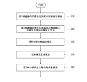
図5は、ロボットシステム100の動作例を示すフローチャートである。
まず、第2関節制御部26は、第1減速機13の角度伝達誤差に係る周波数ωを算出する。第2関節制御部26は、第1関節制御部21から取得した第1モータ11に対する速度指令値及び第1モータ11の出力軸1回転あたりの角度伝達誤差の波の数に基づいて、第1減速機13の角度伝達誤差に係る周波数ωを算出する(ステップS10)。周波数ωは、第1モータ11の角速度の変化により、時々刻々と変化する値である。
なお、上述の通り、ロボットシステム100は、角度伝達誤差に基づく微振動及びロボットアーム4の共振による振幅の増大を抑制するように動作するシステムであり、以下では角度伝達誤差の周波数とロボットアーム4の固有振動数とが一致するものとして周波数ωを用いる。
次に、第2関節制御部26は、第1減速機13の角度伝達誤差に係る周期的な変化が一周期2π/ω経過する間、第2電流値i2に含まれる第1減速機13の角度伝達誤差の周波数ωと同期する成分u(t)の振幅及び位相をフーリエ展開によって算出する(ステップS20)。
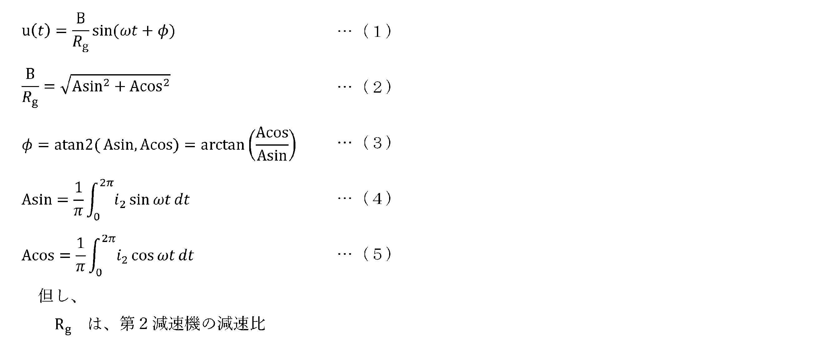
次に、第2関節制御部26は、算出した値B及びφを用いて、n番目の周期における第2関節8の振動θ2n(t)を以下の式(6)によって算出することにより、ロボットアーム4に生じた振動のうち、第2関節8の回動軸線周りに生じた振動θ2n(t)を推定する(ステップS30)。


また、動作補正量θmn+1(t)の振幅Anは、第2関節8に生じた振動と相殺させ、この振動を解消するような大きな制御入力を与える値ではなく、振動の振幅が共振によって増大することを抑制する程度に小さい値であり、例えば、第2関節8に生じた振動の振幅の1/10以下の値である。これによって、第2関節8に生じた振動の振幅が許容範囲を超えて大きくなることを防止することができ、且つ、振動の推定が外れた場合において、振動の振幅を誤って大幅に増大させてしまうことを防止することができる。
次に、第2関節制御部26は、指令部3から入力された第2モータ16に対する第2目標回転角θt2と、第2エンコーダ17が検出した第2モータ16の出力軸16aの実回転角θ2との偏差に基づき、n+1番目の周期における第2モータ16に供給する第2電流値i2を算出する際、動作補正量θmn+1を加味して第2電流値i2を算出する。すなわち、第2関節制御部26は、n+1番目の周期における位置指令値に動作補正量θmn+1を加算して、位置指令値を補正する。そして、第2関節制御部26は、この補正した位置指令値に基づいて第2電流値i2を算出する。そして、第2関節制御部26は、第2電流値i2に基づき第2モータ16に電流を供給し第2モータ16の出力軸16aの回転角を制御する(ステップS50)。
次に、第2関節制御部26は、再度ステップS10を実行する。すなわち、n番目の周期において実施した処理を、n+1番目の周期においても実施する。このように、第2関節制御部26は、ステップS10~ステップS50を繰り返し実行する。
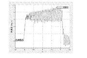
図6Aは、ロボットシステム100のロボットアーム4に生じた振動の測定結果を示すグラフであり、振動抑制制御を実施しない場合における測定結果を示すグラフである。図6Bは、ロボットシステム100のロボットアーム4に生じた振動の測定結果を示すグラフであり、振動抑制制御を実施した場合における測定結果を示すグラフである。図6A及び図6Bにおいては、縦軸に振動の角速度をとり、横軸に時間をとっている。図6Aに示すように、振動を抑制する制御入力を加えていない場合は、振動が時間の経過とともに増大しているのに対し、図6Bに示すように、振動を抑制する制御入力を加えた場合は、振動が一定の振幅に有意に抑制されていることがわかる。
以上に説明したように、本発明のロボットシステム100は、第1関節7及び第2関節8を含む複数の関節を有するロボットアーム4と、出力軸13bが第1関節7に接続された第1減速機13と、出力軸11aが第1減速機13の入力軸13aに接続され、第1減速機13を介して第1関節7を回動させる第1モータ11とを有する第1関節駆動部9と、上位装置から入力された第1モータ11に対する第1動作目標に基づいて第1モータ11の出力軸11aの動作を制御する第1関節制御部21と、出力軸16aが第2関節8に接続され、第2関節8を回動させる第2モータ16を有する第2関節駆動部10と、第2モータ16の出力軸16aの実動作の情報を取得する検知部17と、上位装置から入力された第2モータ16に対する第2動作目標及び第2モータ16の出力軸16aの実動作θ1との偏差に基づき第2モータ16に供給する第2電流値i2を算出し、且つ第2電流値i2に基づき第2モータ16に電流を供給し第2モータ16の出力軸16aの動作を制御する第2関節制御部26と、を備え、第2関節制御部26は、第2電流値i2(又は第2モータ16の出力軸16aの実動作)の時間変化に含まれる第1減速機13の出力軸13bの角度位置、角速度又はトルクの周期的な変化の周波数と同じ周波数成分に基づいて、第2関節8の回動軸線周りのロボットアーム4の振動を推定し、推定したロボットアーム4の振動を抑制するように第2モータ16の出力軸16aの動作を補正する。
この構成によれば、第1減速機13の角度伝達誤差に起因するロボットアーム4の振動を抑制し、ハンド5の軌跡精度を向上させることができる。また、簡素な構成で軌跡精度を向上させることができ、製造コストも安価となる。
また、第1減速機13の出力軸13bの角度位置、角速度又はトルクの周期的な変化は、第1関節駆動部9の特性に起因する変化であってもよい。
この構成によれば、第1関節駆動部9の特性に起因する第1減速機13の出力軸13bの角度位置、角速度又はトルクの周期的な変化に基づくロボットアーム4の振動を適切に抑制することができる。
更に、第1減速機13の出力軸13bの角度位置、角速度又はトルクの周期的な変化の周波数は、第1減速機13の角度伝達誤差の周波数であってもよい。
この構成によれば、第1減速機13の角度伝達誤差に基づくロボットアーム4の振動を適切に抑制することができる。
また、第2関節制御部26が推定する第2関節8の回動軸線周りのロボットアーム4の振動は、第1減速機13の角度伝達誤差に起因する振動であってもよい。
この構成によれば、第1減速機13の角度伝達誤差に起因するロボットアーム4の振動を抑制することができるロボットシステムを適切に構成することができる。
更に、第2関節制御部26は、第2電流値i2(又は第2モータ16の出力軸16aの実動作)の時間変化に含まれる周波数成分のうち第1減速機13の出力軸13bの角度位置、角速度又はトルクの周期的な変化の周波数と同じ周波数成分の振幅を算出し、振幅に基づいて第2関節8の回動軸線周りのロボットアーム4の振動を推定してもよい。
この構成によれば、より精確に第1減速機13の角度伝達誤差に起因するロボットアーム4の振動を抑制することができる。
また、第2関節8の回動軸線は、第1減速機13の出力軸13bの回動軸線に対して傾斜していてもよい。
この構成によれば、第1減速機13の出力軸13bの回動軸線と異なる回動軸線周りの振動を抑制することができる。すなわち、第1減速機13の出力軸13bの回動軸線R1を中心とする円周方向への振動以外の振動、すなわち軸線R2、R3を中心とする円周方向への振動を抑制することができる。
<変形例>
上記実施の形態においては、動作補正量θmn+1は式(7)で表される値としたがこれに限られるものではない。例えば、以下の式(8)で表される値としてもよい。
上記実施の形態においては、動作補正量θmn+1は式(7)で表される値としたがこれに限られるものではない。例えば、以下の式(8)で表される値としてもよい。

また、上記実施の形態においては、第2関節8の回動軸線は、第1関節7の回動軸線と直交する方向に延びる軸線であったがこれに限られるものではなく、第1関節7の回動軸線に対して任意の相対的な姿勢を有していてもよい。例えば、第2関節8の回動軸線は、第1関節7の回動軸線と平行に延びていてもよく、この場合においては、ロボットシステム100は、第1減速機13の角度伝達誤差を補償することができる。
更に、上記実施の形態において、第2関節制御部26は、第1減速機13の角度伝達誤差に起因する振動を抑制するように、第1減速機13の角度伝達誤差の角度位置の周期的な変化の周波数に基づいて動作補正量を算出したが、これに限られるものではない。第2関節制御部26は、角度伝達誤差以外の第1関節駆動部9の特性に起因する第1減速機13の出力軸13bの角度位置、角速度又はトルクの周期的な変化の周波数を用いて動作補正量を算出してもよく、例えば第1関節駆動部9のトルクリップルに起因する第1減速機13の出力軸13bのトルクの周期的な変化の周波数に基づいて動作補正量を算出してもよい。
上記説明から、当業者にとっては、本発明の多くの改良や他の実施形態が明らかである。したがって、上記説明は、例示としてのみ解釈されるべきであり、本発明を実行する最良の態様を当業者に教示する目的で提供されたものである。本発明の精神を逸脱することなく、その構造及び/又は機能の詳細を実質的に変更できる。
1 ロボット
2 制御部
3 基部
3 指令部
4 ロボットアーム
5 ハンド
7 第1関節
8 第2関節
9 第1関節駆動部
10 第2関節駆動部
11 第1モータ
13 第1減速機
16 第2モータ
17 第2エンコーダ
21 第1関節制御部
26 第2関節制御部
100 ロボットシステム
2 制御部
3 基部
3 指令部
4 ロボットアーム
5 ハンド
7 第1関節
8 第2関節
9 第1関節駆動部
10 第2関節駆動部
11 第1モータ
13 第1減速機
16 第2モータ
17 第2エンコーダ
21 第1関節制御部
26 第2関節制御部
100 ロボットシステム
Claims (7)
- 第1関節及び第2関節を含む複数の関節を有するロボットアームと、
出力軸が前記第1関節に接続された第1減速機と、出力軸が前記第1減速機の入力軸に接続され、該第1減速機を介して前記第1関節を回動させる第1モータとを有する第1関節駆動部と、
上位装置から入力された前記第1モータに対する第1動作目標に基づいて前記第1モータの前記出力軸の動作を制御する第1関節制御部と、
出力軸が前記第2関節に接続され、前記第2関節を回動させる第2モータを有する第2関節駆動部と、
前記第2モータの前記出力軸の実動作の情報を取得する検知部と、
前記上位装置から入力された前記第2モータに対する第2動作目標及び前記第2モータの前記出力軸の実動作との偏差に基づき前記第2モータに供給する第2電流値を算出し、且つ該第2電流値に基づき前記第2モータに電流を供給し前記第2モータの前記出力軸の動作を制御する第2関節制御部と、を備え、
前記第2関節制御部は、前記第2電流値又は前記第2モータの前記出力軸の実動作の時間変化に含まれる前記第1減速機の前記出力軸の角度位置、角速度又はトルクの周期的な変化の周波数と同じ周波数成分に基づいて、前記第2関節の回動軸線周りの前記ロボットアームの振動を推定し、推定した前記ロボットアームの振動を抑制するように前記第2モータの前記出力軸の動作を補正する、ロボットシステム。 - 前記第1減速機の出力軸の角度位置、角速度又はトルクの周期的な変化は、前記第1関節駆動部の特性に起因する変化である、請求項1に記載のロボットシステム。
- 前記第1減速機の出力軸の角度位置、角速度又はトルクの周期的な変化の周波数は、前記第1減速機の角度伝達誤差の周波数である、請求項1に記載のロボットシステム。
- 前記第2関節制御部が推定する前記第2関節の回動軸線周りの前記ロボットアームの振動は、前記第1減速機の角度伝達誤差に起因する振動である、請求項3に記載のロボットシステム。
- 前記第2関節制御部は、前記第2電流値又は前記第2モータの前記出力軸の実動作の時間変化に含まれる周波数成分のうち前記第1減速機の前記出力軸の角度位置、角速度又はトルクの周期的な変化の周波数と同じ周波数成分の振幅を算出し、該振幅に基づいて前記第2関節の回動軸線周りの前記ロボットアームの振動を推定する、請求項1乃至4の何れかに記載のロボットシステム。
- 前記第2関節の回動軸線は、前記第1減速機の前記出力軸の回動軸線に対して傾斜する、請求項1乃至5の何れか1に記載のロボットシステム。
- 第1関節及び第2関節を含む複数の関節を有するロボットアームと、
出力軸が前記第1関節に接続された第1減速機と、出力軸が前記第1減速機の入力軸に接続され、該第1減速機を介して前記第1関節を回動させる第1モータとを有する第1関節駆動部と、
上位装置から入力された前記第1モータに対する第1動作目標に基づいて前記第1モータに供給する第1電流値を算出し、且つ該第1電流値に基づき前記第1モータに電流を供給し前記第1モータの前記出力軸の動作を制御する第1関節制御部と、
出力軸が前記第2関節に接続され、前記第2関節を回動させる第2モータを有する第2関節駆動部と、
前記第2モータの前記出力軸の実動作の情報を取得する検知部と、
前記上位装置から入力された前記第2モータに対する第2動作目標及び前記第2モータの前記出力軸の実動作との偏差に基づき前記第2モータに供給する第2電流値を算出し、且つ該第2電流値に基づき前記第2モータに電流を供給し前記第2モータの前記出力軸の動作を制御する第2関節制御部と、を備えるロボットシステムの制御方法であって、
前記第2関節制御部が前記第2電流値又は前記第2モータの前記出力軸の実動作の時間変化に含まれる前記第1減速機の前記出力軸の角度位置、角速度又はトルクの周期的な変化と同じ周波数成分に基づいて、前記第2関節の回動軸線周りの前記ロボットアームの振動を推定するステップと、
推定した前記ロボットアームの振動を抑制するように前記第2モータの前記出力軸の動作を補正するステップとを有する、ロボットシステムの制御方法。
Priority Applications (1)
| Application Number | Priority Date | Filing Date | Title |
|---|---|---|---|
| CN201980045065.9A CN112584989B (zh) | 2018-07-06 | 2019-07-05 | 机器人系统和机器人系统的控制方法 |
Applications Claiming Priority (4)
| Application Number | Priority Date | Filing Date | Title |
|---|---|---|---|
| JP2018129328 | 2018-07-06 | ||
| JP2018-129328 | 2018-07-06 | ||
| JP2018-163554 | 2018-08-31 | ||
| JP2018163554A JP7121599B2 (ja) | 2018-07-06 | 2018-08-31 | ロボットシステム及びロボットシステムの制御方法 |
Publications (1)
| Publication Number | Publication Date |
|---|---|
| WO2020009237A1 true WO2020009237A1 (ja) | 2020-01-09 |
Family
ID=69060454
Family Applications (1)
| Application Number | Title | Priority Date | Filing Date |
|---|---|---|---|
| PCT/JP2019/026891 Ceased WO2020009237A1 (ja) | 2018-07-06 | 2019-07-05 | ロボットシステム及びロボットシステムの制御方法 |
Country Status (1)
| Country | Link |
|---|---|
| WO (1) | WO2020009237A1 (ja) |
Citations (5)
| Publication number | Priority date | Publication date | Assignee | Title |
|---|---|---|---|---|
| JPH04310112A (ja) * | 1991-04-09 | 1992-11-02 | Matsushita Electric Ind Co Ltd | ロボットアームのサーボ制御装置 |
| JP2010149203A (ja) * | 2008-12-24 | 2010-07-08 | Yaskawa Electric Corp | ロボット制御装置およびロボットシステム |
| JP2011224662A (ja) * | 2010-04-15 | 2011-11-10 | Yaskawa Electric Corp | ロボット制御装置の補正パラメータ同定装置 |
| JP2014136260A (ja) * | 2013-01-15 | 2014-07-28 | Daihen Corp | 制御装置 |
| WO2018235812A1 (ja) * | 2017-06-21 | 2018-12-27 | 川崎重工業株式会社 | ロボットシステム及びロボットシステムの制御方法 |
-
2019
- 2019-07-05 WO PCT/JP2019/026891 patent/WO2020009237A1/ja not_active Ceased
Patent Citations (5)
| Publication number | Priority date | Publication date | Assignee | Title |
|---|---|---|---|---|
| JPH04310112A (ja) * | 1991-04-09 | 1992-11-02 | Matsushita Electric Ind Co Ltd | ロボットアームのサーボ制御装置 |
| JP2010149203A (ja) * | 2008-12-24 | 2010-07-08 | Yaskawa Electric Corp | ロボット制御装置およびロボットシステム |
| JP2011224662A (ja) * | 2010-04-15 | 2011-11-10 | Yaskawa Electric Corp | ロボット制御装置の補正パラメータ同定装置 |
| JP2014136260A (ja) * | 2013-01-15 | 2014-07-28 | Daihen Corp | 制御装置 |
| WO2018235812A1 (ja) * | 2017-06-21 | 2018-12-27 | 川崎重工業株式会社 | ロボットシステム及びロボットシステムの制御方法 |
Similar Documents
| Publication | Publication Date | Title |
|---|---|---|
| US11559891B2 (en) | Robot system and method for controlling robot system | |
| JP7117827B2 (ja) | モータ制御システム、モータ制御システムの制御方法、及びロボットシステム | |
| JP6374274B2 (ja) | 制御装置及び減速機システム | |
| CN104736303B (zh) | 多关节机器人的摆动控制装置 | |
| CN107379016A (zh) | 可动部的振动测定方法、机器人的振动测定方法以及控制装置 | |
| JP6860417B2 (ja) | 減速機角度伝達誤差同定システム及び減速機角度伝達誤差同定方法 | |
| CN104349873A (zh) | 多关节机器人的弹性变形补偿控制装置以及控制方法 | |
| WO2013031465A1 (ja) | 制御方法及び制御装置 | |
| JP5277946B2 (ja) | ロボット制御装置およびロボットシステム | |
| JP2016078149A (ja) | ロボット装置の制御方法及びロボット装置、プログラム及び記録媒体 | |
| JP7121599B2 (ja) | ロボットシステム及びロボットシステムの制御方法 | |
| WO2020009237A1 (ja) | ロボットシステム及びロボットシステムの制御方法 | |
| JP2018202589A (ja) | 制御装置、ロボット、およびロボットシステム | |
| JP6814441B2 (ja) | 駆動機械の学習制御装置及び学習制御方法 | |
| JP6252272B2 (ja) | 垂直多関節型ロボットの位置誤差抑制方法 | |
| JP6391489B2 (ja) | モータ制御装置 | |
| JP5262880B2 (ja) | ロボット制御装置 | |
| JP2024155507A (ja) | ロボット | |
| JP2019055456A (ja) | ロボットの制御装置 |
Legal Events
| Date | Code | Title | Description |
|---|---|---|---|
| 121 | Ep: the epo has been informed by wipo that ep was designated in this application |
Ref document number: 19831368 Country of ref document: EP Kind code of ref document: A1 |
|
| NENP | Non-entry into the national phase |
Ref country code: DE |
|
| 122 | Ep: pct application non-entry in european phase |
Ref document number: 19831368 Country of ref document: EP Kind code of ref document: A1 |